

Page 1

Models 340, 341, 342
Slush Freezers
Operating Instructions
028764--M
1/97
Page 2

Complete this page for quick reference when service is required:
Taylor Distributor:
Address:
Phone:
Service:
Parts:
Date of Installation:
Information found on the data label:
Model Number:
Serial Number:
Electrical Specs: Voltage Cycle
Phase
Maximum Fuse Size: A
Minimum Wire Ampacity: A
E January, 1997 Taylor
All rights reserved.
028764--M
Taylor Company
The word T aylor and the Crown design
are registered trademarks in the United States
of America and certain other countries.
a division of Carrier Commercial Refrigeration, Inc.
750 N. Blackhawk Blvd.
Rockton, IL 61072
Page 3

Table of Contents
______________________________________________________________________________
Section 1 To the Installer 1............................................
Water Connections 1....................................................
Air Cooled Units 1.......................................................
Electrical Connections 1.................................................
Section 2 To the Operator 2...........................................
Compressor Warranty Disclaimer 2.......................................
Section 3 Safety 3....................................................
Section 4 Operator Parts Identification 4...............................
Section 5 Important: To the Operator 9.................................
Control Switch 9........................................................
Consistency Control 9...................................................
Indicator Light - “Mix Low” 9..............................................
For Your Information 9...................................................
Section 6 Operating Procedures 10.....................................
Assembly 10............................................................
Sanitizing 14............................................................
Priming 15..............................................................
Closing Procedure 16....................................................
Draining Product From the Freezing Cylinder 17.............................
Rinsing 17..............................................................
Cleaning 18.............................................................
Disassembly 19..........................................................
Brush Cleaning 19.......................................................
Section 7 Important: Operator Checklist 20..............................
During Cleaning and Sanitizing 20.........................................
Troubleshooting Bacterial Count 20........................................
Regular Maintenance Checks 20...........................................
Winter Storage 21........................................................
Section 8 Troubleshooting Guide 22....................................
Section 9 Parts Replacement Schedule 25...............................
Section 10 Parts List 26.................................................
Wiring Diagrams 32......................................................
Note: Continuing research results in steady improvements; therefore, information
in this manual is subject to change without notice.
Table of Contents Models 340, 341, 342
Page 4

Notes:
Models 340, 341, 342
Table of Contents
Page 5

Section 1 To the Installer
This machine is designed for indoor use only.
DO NOT install the machine in an area where
a water jet could be used to clean or rinse the machine.
Failure to follow this instruction may result in serious
electrical shock.
Water Connections
(Water Cooled Units Only)
An adequate cold water supply with a hand shut-off
valve must be provided. On the underside of the base
pan, two 3/8” I.P.S. (for single-head units) or two 1/2”
I.P.S. (for double-head units) water connections for
inlet and outlet have been provided for easy hook-up.
1/2” inside diameter water lines should be connected
to the machine. (Flexible lines are recommended, if
local codes permit.) Depending on local water
conditions, it may be advisable to install a water
strainer to prevent foreign substances from clogging
the automatic water valve. There will be only one water
“in” and one water “out” connection for both
double-head and single-head units. DO NOT install a
hand shut-off valve on the water “out” line! Water
should always flow in this order: first, through the
automatic water valve; second, through the
condenser; and third, through the outlet fitting to an
opentrapdrain.
circuit ampacity and electrical specifications. For
proper power connections, refer to the wiring diagram
provided inside of the electrical box.
In the United States, this equipment is intended to be
installed in accordance with the National Electrical
Code (NEC), ANSI/NFPA 70--1987. The purpose of
the NEC code is the practical safeguarding of persons
and property from hazards arising from the use of
electricity. This code contains provisions considered
necessary for safety. Compliance therewith and
proper maintenance will result in an installation
essentially free from hazard!
In all other areas of the world, equipment should be
installed in accordance with the existing local codes.
Please contact your local authorities.
Stationary appliances which are not equipped with a
power cord and a plug or other device to disconnect
the appliance from the power source must have an
all--pole disconnecting device with a contact gap of at
least 3 mm installed in the external installation.
CAUTION: THIS EQUIPMENT MUST BE
PROPERLY GROUNDED! FAILURE TO DO SO
CAN RESULT IN SEVERE PERSONAL INJURY
FROM ELECTRICAL SHOCK!
Air Cooled Units
The model 340 air cooled unit requires a minimum of
6” (152 mm) of clearance around both sides of the
freezer. It is recommended to install a skirt to one side
of the unit, and to place the back of the unit against a
wall. The models 341 and 342 air cooled units require
a minimum of 3” (76 mm) of air clearance around all
sides.
Failure to allow adequate clearance can reduce the
refrigeration capacity of the freezer and possibly
cause permanent damage to the compressor.
Electrical Connections
Each freezer requires one power supply for each data
label. Check the data label(s) on the freezer for fuse,
Models 340, 341, 342 To the Installer
Beater rotation must be clockwise as viewed looking
into the freezing cylinder.
Note: The following procedures should be performed
by a trained service technician.
To correct rotation on a three-phase unit, interchange
any two incoming power supply lines at the freezer
main terminal block only .
To correct rotation on a single-phase unit, change the
leads inside the beater motor. (Follow the diagram
printedonthemotor.)
Electrical connections are made directly to the
terminal block. The terminal block is provided in the
main control box located under the upper left side
panel on counter models or behind the service panel
on console models.
050307
1
Page 6

Section 2 To the Operator
The freezer you have purchased has been carefully
engineered and manufactured to provide dependable
operation. The TaylorSlush Models 340, 341, and 342,
when properly operated and cared for, will produce a
consistent quality product. Like all mechanical
products, these machines will require cleaning and
maintenance. A minimum amount of care and
attention is necessary if the operating procedures
outlined in this manual are followed closely.
This Operator’s Manual should be read before
operating or performing any maintenance on your
equipment.
Your Taylor freezer will NOT eventually compensate
and correct for any errors during the set-up or filling
operations. Thus, the initial assembly and priming
procedures are of extreme importance. It is strongly
recommended that personnel responsible for the
equipment’s operation study these procedures
together in order to be properly trained and to make
sure that no misunderstandings exist.
In the event you should require technical assistance,
please contact your local authorized Taylor Distributor.
If the crossed out wheeled bin symbol is
affixed to this product, it signifies that this product is
compliant with the EU Directive as well as other similar
legislation in effect after August 13, 2005. Therefore,
it must be collected separately after its use is
completed, and cannot be disposed as unsorted
municipal waste.
The user is responsible for returning the product to the
appropriate collection facility ,as specified by your local
code.
For additional information regarding applicable local
laws, please contact the municipal facility and/or local
distributor.
Compressor Warranty Disclaimer
The refrigeration compressor(s) on this machine are
warranted for the term indicated on the warranty card
accompanying this machine. However, due to the
Montreal Protocol and the U.S. Clean Air Act
Amendments of 1990, many new refrigerants are
being tested and developed, thus seeking their way
into the service industry. Some of these new
refrigerants are being advertised as drop-in
replacements for numerous applications. It should be
noted that, in the event of ordinary service to this
machine’s refrigeration system, only the refrigerant
specified on the affixed data label should be used.
The unauthorized use of alternate refrigerants will void
your compressor warranty . It will be the owner’s
responsibility to make this fact known to any technician
he employs.
It should also be noted that Taylor does not warrant the
refrigerant used in its equipment. For example, if the
refrigerant is lost during the course of ordinary service
to this machine, Taylor has no obligation to either
supply or provide its replacement either at billable or
unbillable terms. Taylor does have the obligation to
recommend a suitable replacement if the original
refrigerant is banned, obsoleted, or no longer available
during the five year warranty of the compressor .
Taylor will continue to monitor the industry and test
new alternates as they are being developed. Should a
new alternate prove, through our testing, that it would
be accepted as a drop-in replacement, then the above
disclaimer would become null and void. To find out the
current status of an alternate refrigerant as it relates to
your compressor warranty, call the local Taylor
Distributor or the Taylor Factory. Be prepared to
provide the Model/Serial Number of the unit in
question.
061211
2
Models 340, 341, 342To the Operator
Page 7
Section 3 Safety
We at Taylor are concerned about the safety of the
operator when he or she comes in contact with the
freezer and its parts. Taylor has gone to extreme
efforts to design and manufacture built-in safety
features to protect both you and the service technician.
As an example, warning labels have been attached to
the freezer to further point out safety precautions to the
operator.
IMPORTANT -- F ailure to adhere to the
following safety precautions may result in severe
personal injury. Failure to comply with these
warnings may damage the machine and its
components. Component damage will result in
part replacement expense and service repair
expense.
S DO NOT allow untrained personnel to
operate this machine.
S DO NOT operate the freezer unless all
service panels and access doors are
restrained with screws.
S DO NOT remove the door, beater, scraper
blades, drive shaft, or torque rotor shaft
unless all control switches are in the OFF
position.
S DO NOT put objects or fingers in the door
spout.
Failure to follow these instructions may result in
contaminated product or severe personal injury to
fingers or hands from hazardous moving parts.
To Operate Safely:
DO NOT operate the freezer without reading
this operator’s manual. Failure to follow this instruction
may result in equipment damage, poor freezer
performance, health hazards, or personal injury.
S DO NOT operate the freezer unless it is
properly grounded.
S DO NOT attempt any repairs unless the
main power supply to the freezer has been
disconnected.
S DO NOT operate the freezer with larger
fuses than specified on the freezer data
label.
Failure to follow these instructions may result in
electrocution or damage to the machine. Contact your
local authorized Taylor Distributor for service.
USE EXTREME CAUTION when removing
the beater assembly. The scraper blades are very
sharp and may cause injury .
These freezers must be placed on a level
surface. Failure to comply may result in personal injury
or equipment damage.
DO NOT obstruct air intake and discharge openings:
Models 341/342: 3” (76 mm) minimum air space on all
sides.
Model 340: 6” (152 mm) minimum air space on sides
and 0” at the rear. It is recommended to install a skirt
to one side of the unit, and to place the back of the unit
against a wall.
Failure to follow this instruction may cause poor
freezer performance and damage to the machine.
These freezers are designed to operate indoors, under
normal ambient temperatures of 70_-- 7 5 _F
(21_-- 2 4 _C). The freezers have successfully
performed in high ambient temperatures of 104_F
(40_C) at reduced capacities.
NOISE LEVEL: Airborne noise emission does not
DO NOT use a water jet to clean or rinse the
freezer. Failure to follow this instruction may result in
serious electrical shock.
Models 340, 341, 342 Safety
exceed 78 dB(A) when measured at a distance of 1.0
meter from the surface of the machine and at a height
of 1.6 meters from the floor.
061211
3
Page 8
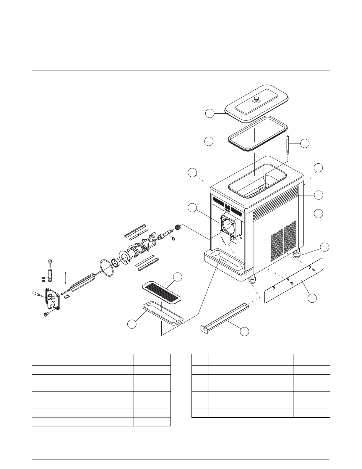
Section 4 Operator Parts Identification
Model 340
1
2
3
9
10
12
13
R
8
11
7
4
6
Item Description Part No.
1 Cover A.-Hopper X38458
2 Gasket-Hopper Cover 038375
3 Tube-Feed 015176-9
4 Skirt-Air Flow 049069
5 Pan-Drip 19-1/2 Long 035034
6 Tray-Drip 013690
7 Shield-Splash 022763
020729
5
Item Description Part No.
8 Panel-Right Side 047007
9 Panel-Rear 047008
10 Panel-Left Side 047006
11 Leg-4” 013458
12 Louver-Side 013631
13 Panel A.-Front X46881
4
Models 340, 341, 342Operator Parts Identification
Page 9
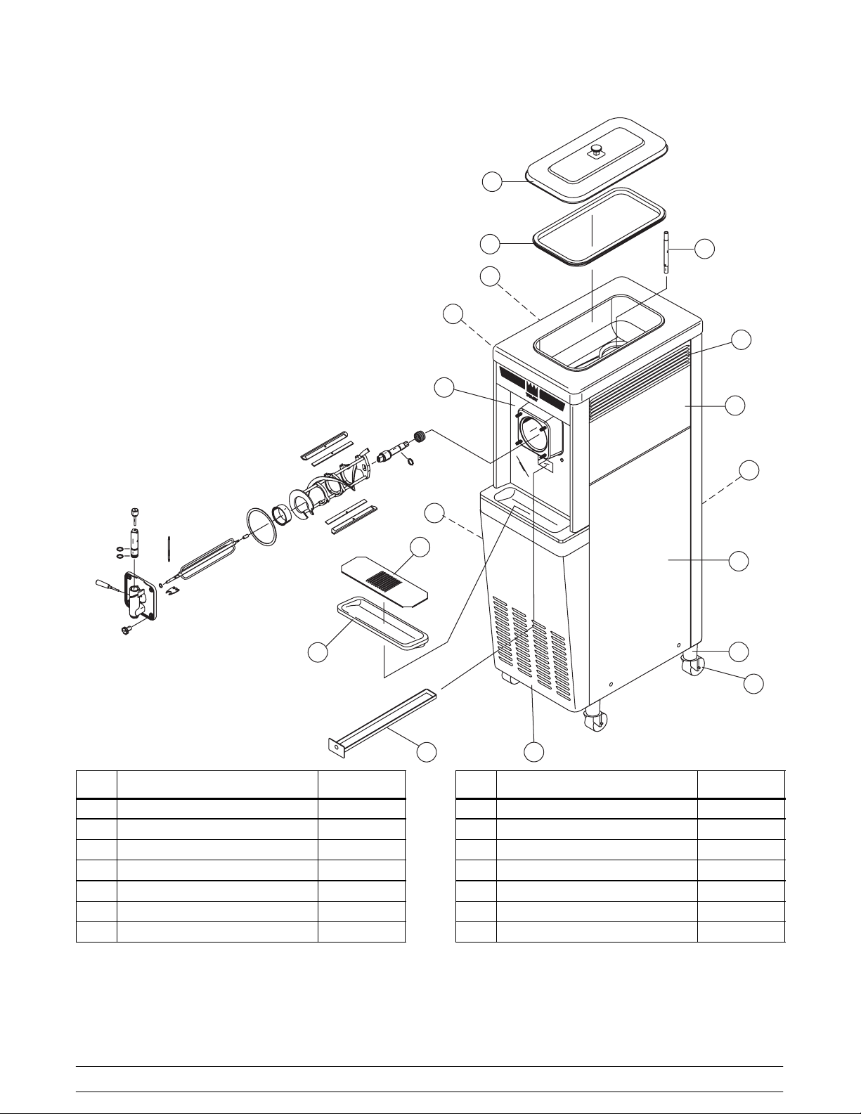
Model 341
1
2
3
12
4
12
13
R
4
8
9
7
9
6
14
10
5
Item Description Part No.
1 Cover A.-Hopper X38458
2 Gasket-Hopper Cover 038375
3 Tube-Feed 015176-9
4 Panel-Upper Side (Left/Right) 024576
5 Pan-Drip 035034
6 Tray-Drip 013690
7 Shield-Splash 022763
Models 340, 341, 342 Operator Parts Identification
Item Description Part No.
8 Panel-Rear 013637
9 Panel A.-Lower Side (Left/Right) X24397
10 Wheel-Caster 018794
11 Panel-Service 013638-SP1
12 Louver-Side (Left/Right) 013631
13 Panel A.-Front X46881
14 Adapter A.-Caster X18915
5
11
020729
Page 10
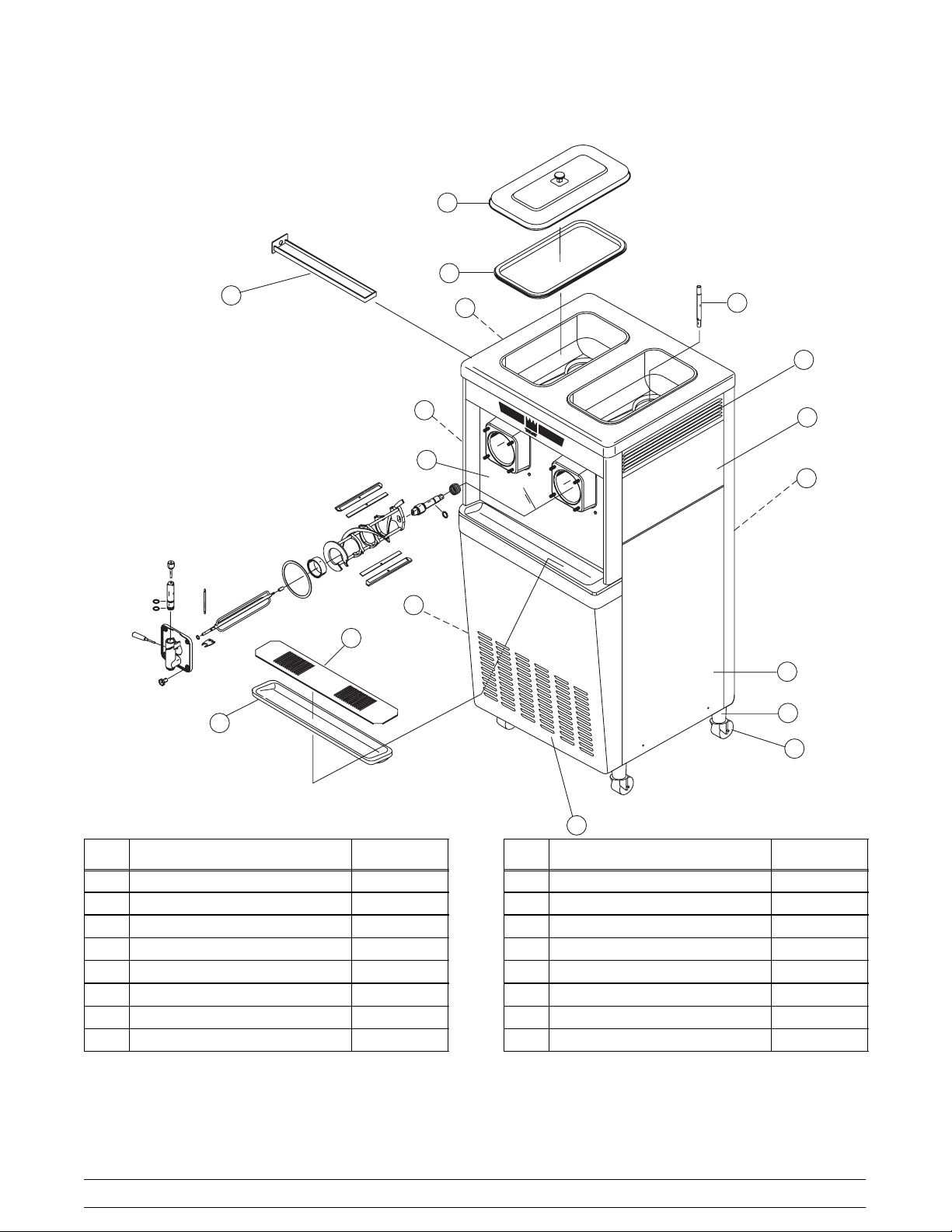
Model 342
1
2
5
11
3
11
14
7
6
Item Description Part No.
4
15
R
13
12
10
16
9
8
Item Description Part No.
1 Cover A.-Hopper X38458
2 Gasket-Hopper Cover 038375
3 Tube-Feed 015176-9
4 Panel-Upper Left Side 028700
5 Pan-Drip 027503
6 Tray-Drip 014533
7 Shield-Splash 037041
8 Panel-Service 024439-SP1
020729
9 Wheel-Caster 018794
10 Panel A.-Lower Right Side X44855
11 Louver-Side (Left/Right) 017471
12 Panel-Rear 017563
13 Panel-Upper Right Side 028701
14 Panel A.-Lower Left Side X44853
15 Panel A.-Front X25807
16 Adapter A.-Caster X18915
6
Models 340, 341, 342Operator Parts Identification
Page 11
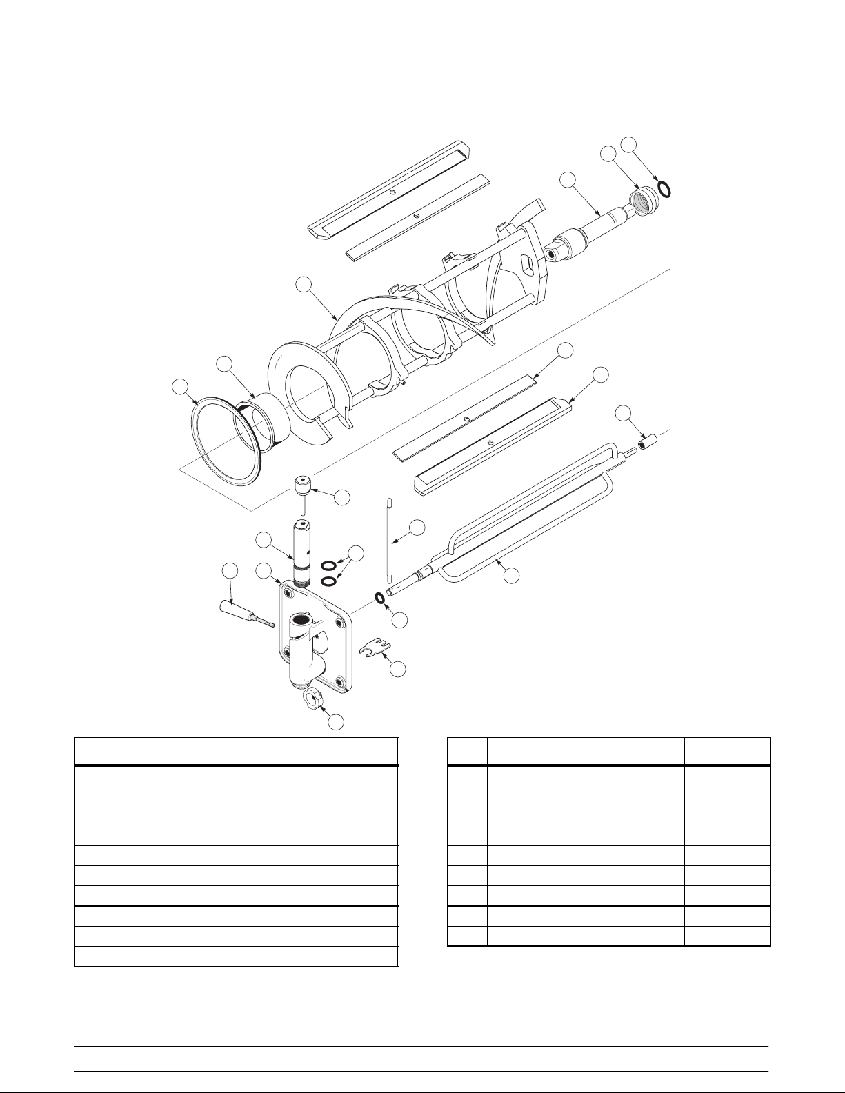
Models 340, 341, 342 Beater Door Assembly
12
15
16
17
10
11
13
19
9
4
3
14
5
2
1
8
7
6
18
Item Description Part No.
1 Door A.-Partial X39248
2 Handle A.-Draw-Slush X25124
3 Valve-Draw 047734
4 Valve A.-Handle Pin X25929
5 O-Ring-1 OD x .139 W 032504
6 Buster-Ice 047735
7 O-Ring-.291 ID x .080 W 018550
*8 Torque Assembly X14488
9 Bearing-Guide 014496
10 Gasket-Door-5.109 D x 5.63 OD 014030
Models 340, 341, 342 Operator Parts Identification
Item Description Part No.
11 Bearing-Front 013116
12 Beater A.-7 QT -1 Pin Support X46233
13 Clip-Scraper Blade*8.75”* 046238
14 Torque Arm 014500
15 Shaft-Beater 035418
16 Seal-Drive Shaft 032560
17 O-Ring-7/8 OD x .139 W 025307
18 Stud Nut 029880
19 Blade-Scraper-Plastic 9 -13/16L 046237
*Note: Use optional Torque Assembly X27027--1,
Arm--Torque 029549, and Spring--Torque*Red* 020232
for soft slush application.
040826
7
Page 12
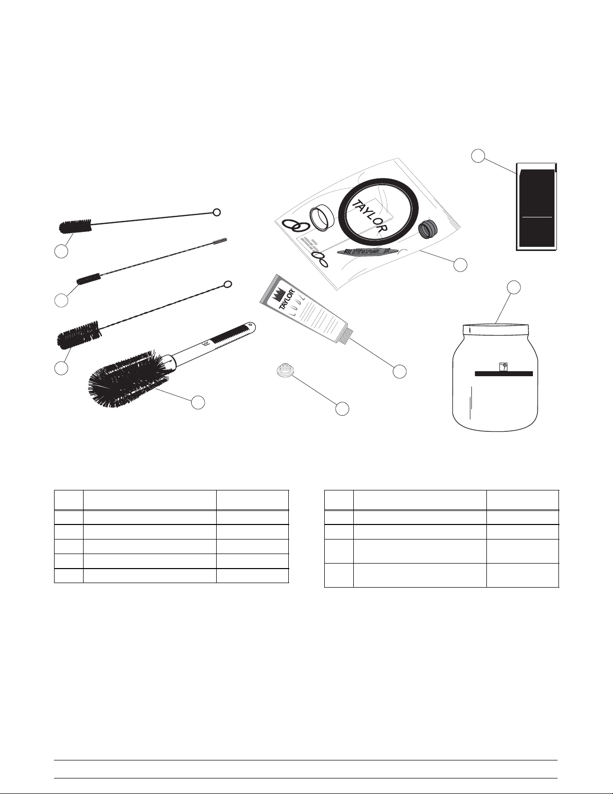
Accessories
L
U
B
E
2
9
KAY-5
®
Sanitizer/Cleaner
KEEPOUT OF REACH OF CHILDREN
CAUTION
FORINSTITUTIONAL USE ONLY
1OZ (28.4 g)
0
6
82
4
0
1
3
6
4
Item Description Part No.
1 Kit A.-Tune Up X39969
2 Brush-Rear Bearing 013071
3 Brush-Double Ended 013072
4 Brush-Mix Pump Body 023316
5 Lubricant-Taylor Lube 047518
R
SSTERA HEEN
5
GREEN LABEL
SANITIZER& CLEANER
(MILKSTONEREMOVER)
8
7
Item Description Part No.
6 Brush-Draw Valve 013073
7 Cap-Restrictor 020213
8 Sanitizer-- Stera Sheen
(Model 342 only)
9 Sanitizer-- Kay 5 (Models 340
& 341)
065293
041082
071017
8
Models 340, 341, 342Operator Parts Identification
Page 13
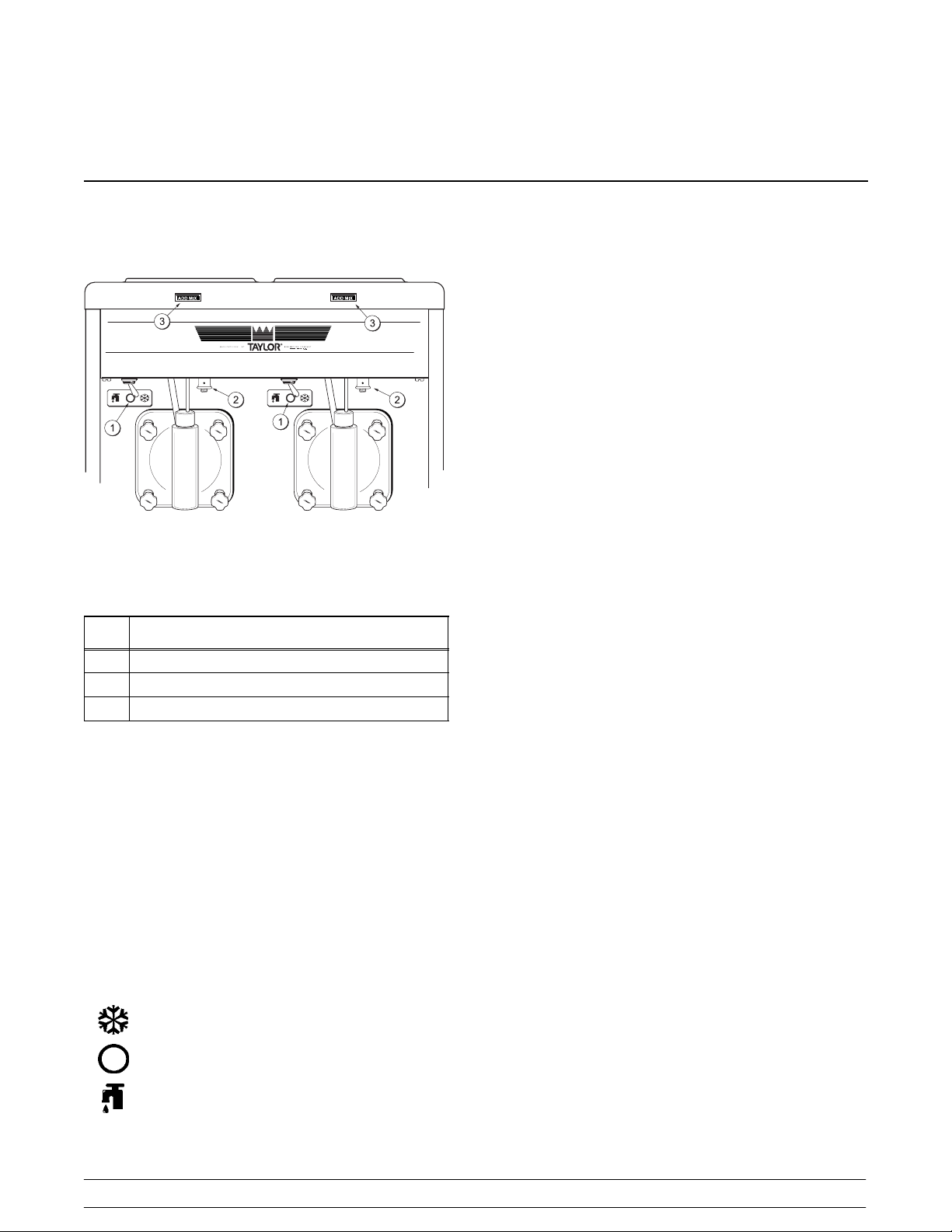
Section 5 Important: To the Operator
Control Switch
The center position is “OFF”. The left position is
“WASH”, which activates only the beater motor. The
right position is “AUTO”, which activates the beater
motor and the refrigeration system.
Consistency Control
The viscosity (thickness) of the slush is controlled by
a sensing device called the consistency control. The
consistency control knob is located under the control
channel. To achieve a thicker slush, turn the knob
clockwise and counterclockwise to achieve a
thinner slush consistency.
Allow the refrigeration system to cycle on and cycle off
two or three times before an accurate consistency can
Figure 1
be evaluated.
Item
1 Control Switch
2 Consistency Control
3 Indicator Light -- “Add Mix”
Description
Symbol Definitions
To better communicate in the International arena, the
words on many of our operator switches and buttons
have symbols to indicate their functions. Your Taylor
equipment is designed with these International
symbols.
The following chart identifies the symbol definitions
used on the operator switches.
=ON/AUTO
=OFF
= WASH
Indicator Light - “Add Mix”
A mix level indicating light is located on the front of the
machine. When the light is on, it indicates that the mix
hopper has a low supply of mix and should be refilled
as soon as possible. If mix is not added, a freeze-up
may occur, causing eventual damage to the beater,
blades, drive shaft, and freezer door.
For Your Information
The Models 340 and 341 come equipped with an
optional rack assembly and four syrup jars. Each syrup
jar holds 16 ounces (453.6 grams) of syrup. One pump
stroke will dispense 1/4 ounce (7 grams) of syrup.
Because of the many different types of syrups on the
market today , the syrup to slush ratio will vary. Consult
the label or manufacturer for the proper amount of
syrup for the desired drink size.
To serve slush product, simply add the flavor and open
the draw valve. The slush product should blend with
the syrup with no stirring necessary. If it does not, the
product is too thick and the consistency control should
be adjusted to a thinner consistency.
Models 340, 341, 342 Important: To the Operator
9
Page 14

Section 6 Operating Procedures
The Model 341 has been selected to illustrate the
pictured step-by-step operating procedures for the
models contained in this manual. Each unit has a 20
quart (18.9 liter) mix hopper and the freezing cylinder
holds 7 quarts (6.6 liters) of slush product. The Model
342 has two mix hoppers and two freezing cylinders;
therefore, duplicate (where it applies) the following
steps for the second side of the Model 342.
We begin our instructions at the point where we enter
the store in the morning and find the parts
disassembled and laid out to air dry from the previous
night’s brush cleaning.
These opening procedures will illustrate how to
assemble these parts into the freezer, sanitize them,
and prime the freezer with slush base in preparation to
serve the first portion.
If you are disassembling the machine for the first time,
or need information to get to this starting point in our
instructions, turn to page 19, “Disassembly” and start
there.
Insert the drive shaft into the freezing cylinder, (square
end first) and into the rear shell bearing, until the seal
fits securely over the rear shell bearing. Be certain the
drive shaft fits into the drive coupling without binding.
Figure 2
Assembly
MAKE SURE CONTROL SWITCH IS IN THE
“OFF” POSITION. Failure to do so may cause injury
from electrocution or hazardous moving parts .
Note: When lubricating parts, use an approved food
grade lubricant (example: Taylor Lube).
Step 1
Install the beater drive shaft. Slide the o-ring into the
first groove on the drive shaft. Lubricate the groove,
o-ring, and shaft portion that comes in contact with the
bearing on the beater drive shaft. DO NOT lubricate
the square end of the drive shaft. Slide the seal over
the shaft and groove until it snaps into place. Fill the
inside portion of the seal with 1/4” more lubricant and
evenly lubricate the flat side of the seal that fits onto the
rear shell bearing.
Figure 3
Step 2
Before installing the beater assembly, check the
scraper blades for any nicks or signs of wear. If any
nicks are present or if the blade is worn, replace both
blades.
10
Models 340, 341, 342Operating Procedures
Page 15

Step 3
If the blades are in good condition, install the scraper
blade clip over the scraper blade. Place the rear
scraper blade over the rear holding pin (knife edge to
the outside). Holding the blade on the beater, turn it
over and install the front blade the same way.
Figure 4
Holding the blade in position, insert the beater
assembly into the freezing cylinder and slide it into
position over the drive shaft. Turn the beater slightly to
be certain that the beater is properly seated. When in
position, the beater will not protrude beyond the front
of the freezing cylinder.
Figure 6
Insert the torque rotor shaft, plastic bearing end first,
making sure that it fits into the hole in the beater drive
shaft. Rotate it several times to check for proper
positioning. The hole in the torque rotor shaft should be
in the 12 o’clock position.
10362
Figure 5
Step 4
Install the torque rotor shaft. Slide the o-ring into the
groove on the front of the shaft and lubricate these
parts to prevent leaking. Place the white, plastic guide
bearing on the rear of the rotor shaft. DO NOT lubricate
the guide bearing.
Figure 7
Step 5
Assemble the freezer door with the “Ice Buster” (door
spout clearing device). T o assemble the door with the
ice buster, install the o-rings on the draw valve and
lubricate.
Figure 8
020807
Models 340, 341, 342 Operating Procedures
11
Page 16

Insert the draw valve into the door, leaving
approximately 1/2” of the valve sticking out the top of
the door.
Figure 9
Rotatethe draw valve so the flatson the top of the draw
valve are perpendicular to the door face.
With the ice buster in place, rotate the draw valve to
allow installation of the draw handle. This will lock the
ice buster in place. Install the draw handle pin, and
close the draw valve by moving the handle to the left.
Figure 12
Place the large rubber gasket into the groove on the
back side of the freezer door.
Figure 10
Insert the ice buster through the door spout and into
the slot located just above the lower o-ring.
Figure 11
Figure 13
12
Models 340, 341, 342Operating Procedures
Page 17

Slide the white, plastic front bearing onto the bearing
hub, making certain that the flanged end of the bearing
is resting against the freezer door. DO NOT lubricate
the door gasket or front bearing.
Figure 14
Step 6
Install the freezer door. Place the front end of the baffle
into the hole in the center of the door. Position the door
onto the four studs on the front of the freezing cylinder
and push the door into place. Install the four
handscrews onto the studs and tighten them equally in
a crisscross pattern to insure that the door is snug. DO
NOT over-tighten the handscrews.
Figure 16
Step 8
Install the rear drip pan and the restrictor cap. Slide the
long drip pan into the hole in the front panel.
Note: If the freezer door does not fit into place easily,
position the open end of the beater assembly in the 11
o’clock position.
Figure 15
Step 7
Rotate the baffle assembly so the hole in the end of the
shaft is vertical. Insert the torque arm between the
draw valve spout supports and into the hole in the
baffle assembly.
Note: During operation, the torque arm rests on the
spout support.
Figure 17
Step 9
Install the front drip tray and splash shield under the
door spout.
Figure 18
Models 340, 341, 342 Operating Procedures
13
Page 18

Step 10
Lay the hopper gasket and feed tube in the bottom of
the mix hopper.
Figure 19
Step 11
(Optional Rack Assembly)
Complete the assembly by inserting the flavor bottles
into the rack assembly on the front of the machine.
Figure 21
Step 3
While the solution is flowing into the freezing cylinder,
brush clean the mix hopper, mix inlet hole, air tube and
mix level sensing probe.
Figure 20
Sanitizing
Step 1
Prepare two gallons (7.6 liters) of an approved 100
PPM chlorine based sanitizing solution (Examples:
Stera--SheenR or Kay-5R). USE WARM WATER
AND FOLLOW THE MANUFACTURER’S SPECIFICATIONS.
Step 2
Pour the two gallons (7.6 liters) of sanitizing solution
into the hopper and allow it to flow into the freezing
cylinder.
071017
Figure 22
Step 4
Place the control switch in the “WASH” position. This
will cause the sanitizing solution in the freezing
cylinder to agitate. Allow the solution to agitate for five
minutes.
Figure 23
14
Models 340, 341, 342Operating Procedures
Page 19

Step 5
Place an empty mix pail beneath the door spout and
move the draw handle to the right. Draw off all the
sanitizing solution. When the sanitizer stops flowing
from the door spout, move the draw handle to the left
and place the control switch in the “OFF” position.
Figure 24
Priming
Step 1
With a mix pail beneath the door spout, move the draw
handle to the right. Fill the hopper with FRESH slush
product and allow it to flow into the freezing cylinder.
This will force out any remaining sanitizing solution.
When full strength mix is flowing from the door spout,
move the draw handle to the left.
Step 6
With sanitized hands, assemble the hopper gasket
around the top edge of the mix hopper. Stand the air
tube in the corner of the hopper.
Figure 25
Figure 26
Step 2
When the slush product has stopped bubbling down
into the freezing cylinder , install the air tube in the mix
inlet hole.
Figure 27
Models 340, 341, 342 Operating Procedures
15
Page 20

Step 3
Place the control switch in the “AUTO” position. When
the unit cycles off, the product will be at serving
viscosity.
Figure 28
Step 4
Place the hopper cover into position.
Step 5
(Optional Flavor Rack Assembly)
To make a refreshing slush product, add the desired
flavor to the bottom of the cup by pressing the pump
handle of the flavor bottle. Move the draw handle to the
right and fill the cup, mixing the flavor with the product
being drawn.
Figure 30
Figure 29
Closing Procedure
To disassemble the Models 340, 341, and 342, the
following items will be needed:
S Two cleaning pails
S Sanitized stainless steel rerun can with lid
S Necessary brushes (provided with the
freezer)
S Cleaner
S Single service towels
16
Models 340, 341, 342Operating Procedures
Page 21

Draining Product From the
Freezing Cylinder
Step 1
Place the control switch in the “OFF” position as far
ahead of cleaning time as possible to allow frozen
product to soften for easier cleaning.
Figure 33
ALWAYS FOLLOW LOCAL HEALTH CODES.
Rinsing
Figure 31
Step 2
Remove the hopper cover, gasket, and air tube and
take these parts to the sink for cleaning.
Figure 32
Step 3
With a sanitized pail under the door spout, place the
control switch in the “WASH” position and move the
draw handle to the right. When all the product stops
flowing from the door spout, move the draw handle to
the left and place the control switch in the “OFF”
position. If local health codes permit, empty the rerun
into the rerun can. Cover the container and place it in
the walk-in cooler.
Step 1
Pour two gallons (7.6 liters) of cool, clean water into
the mix hopper. With the brushes provided, scrub the
mix hopper, mix inlet hole, and mix level sensing
probe.
Figure 34
Step 2
With a mix pail beneath the door spout, place the
control switch in the “WASH” position and move the
draw handle to the right. Drain all the rinse water from
the freezing cylinder. When the rinse water stops
flowing from the door spout, move the draw handle to
the left and place the control switch in the “OFF”
position.
Repeat this procedure until the rinse water being
drawn from the freezing cylinder is clear.
Models 340, 341, 342 Operating Procedures
17
Page 22

Cleaning
Step 1
Prepare two gallons (7.6 liters) of an approved cleaning solution (Examples: Stera--SheenR or Kay-5R).
USE WARM WATER AND FOLLOW THE MANUFACTURER’S SPECIFICATIONS.
Step 2
Pour the two gallons (7.6 liters) of cleaning solution
into the hopper and allow it to flow into the freezing
cylinder.
Figure 35
Step 3
While the solution is flowing into the freezing cylinder,
brush clean the mix hopper and the mix inlet hole.
Step 4
Place the control switch in the “WASH” position. This
will cause the cleaning solution in the freezing cylinder
to agitate.
Figure 37
Step 5
Place an empty mix pail beneath the door spout and
move the draw handle to the right. Draw off all of the
cleaning solution. When the solution stops flowing
from the door spout, move the draw handle to the left
and place the control switch in the “OFF” position.
071017
Figure 36
18
Figure 38
Models 340, 341, 342Operating Procedures
Page 23

Disassembly
MAKE SURE CONTROL SWITCH IS IN THE
“OFF” POSITION. Failure to do so may cause injury
from electrocution or hazardous moving parts .
hand, push the top of the o-ring forward and it will roll
out of the groove and can be easily removed.
If there is more than one o-ring to be removed, always
remove the rear o-ring first. This will allow the o-ring to
slide over the forward rings without falling into the open
grooves.
Step 1
Remove the torque arm, handscrews, freezer door,
torque rotor, beater assembly, scraper blades, and the
drive shaft from the freezing cylinder. Take these parts
to the sink for cleaning.
Step 2
Remove the front drip tray and splash shield and take
them to the sink for cleaning.
Figure 39
Step 3
Remove the restrictor cap, draw valve handle, draw
valve pin, draw valve, front bearing, ice buster, and
gasket from the freezer door . Remove the two o-rings
from the draw valve. Remove the o-ring and guide
bearing from the torque rotor.
Step 4
Thoroughly brush clean all disassembled parts in the
cleaning solution, making sure all lubricant and mix film
is removed. Place all the cleaned parts on a clean dry
surfacetoairdry.
Step 5
Return to the freezer with a small amount of cleaning
solution. With the black bristle brush, brush clean the
rear shell bearing(s) at the back of the freezing
cylinder(s).
Brush Cleaning
Step 1
Prepare a sink with an approved cleaning solution (Examples: Stera--SheenR or Kay-5R). USE WARM
WATER AND FOLLOW THE MANUFACTURER’S
SPECIFICATIONS.
If an approved cleaner other than Stera--SheenR or
Kay-5R is used, dilute according to label instructions.
IMPORTANT: Follow label directions, as too
STRONG of a solution can cause parts damage, while
too MILD of a solution will not provide adequate
cleaning. Make sure all brushes provided with the
freezer are available for brush cleaning.
Step 2
Remove the o-ring and seal from the drive shaft.
Note: To remove o-rings, use a single service towel to
grasp the o-ring. Apply pressure in an upward direction
until the o-ring pops out of its groove. With the other
Models 340, 341, 342 Operating Procedures
Step 6
Remove the rear drip pan.
Note: If the drip pan is filled with an excessive amount
of mix, it is an indication that the drive shaft o-ring, seal
or both should be replaced or properly lubricated.
Step 7
Wipe clean all exterior surfaces of the freezer.
19
Figure 40
071017
Page 24

Section 7 Important: Operator Checklist
During Cleaning and Sanitizing
ALWAYS FOLLOW LOCAL HEALTH CODES.
Cleaning and sanitizing schedules are governed by
your State or local regulatory agencies and must be
followed accordingly. The following check points
should be stressed during the cleaning and sanitizing
operations.
WE RECOMMEND DAILY CLEANING AND
SANITIZING.
T roubleshooting Bacterial Count
j 1. Thoroughly clean and sanitize the machine
regularly, including complete disassembly and
brush cleaning.
j 2. Use all brushes supplied for thorough cleaning.
The brushes are specially designed to reach all
mix passageways.
in a sanitized, covered stainless steel container
and used the following day.
Regular Maintenance Checks
j 1. Rotate scraper blades to allow both sides of the
knife edge to wear evenly. This will contribute to
self-sharpening and help maintain fast, efficient
freezing.
j 2. Replace scraper blades that are nicked or
damaged.
j 3. Before installing the beater, be certain that the
scraper blades are properly attached over the
beater pins.
j 4. Dispose of o-rings and seals if they are worn,
torn, or fit too loosely, and replace them with
new ones.
j 5. Follow all lubricating procedures as outlined in
“Assembly”.
j 6. Check the rear shell bearing for signs of wear
(excessive mix leakage in rear drip pan) and be
certain it is properly cleaned.
j 3. Use the white bristle brush to clean the mix inlet
hole which extends from the mix hopper down
to the rear of the freezing cylinder.
j 4. Use the black bristle brush to thoroughly clean
the rear shell bearing located at the rear of the
freezing cylinder. Be sure to have a generous
amount of cleaning solution on the brush.
j 5. Properly prepare the cleaning and sanitizing
solutions. Read and follow label directions
carefully. Too strong of a solution may damage
the parts and too weak of a solution will not do
an adequate job of cleaning or sanitizing.
j 6. Using a screwdriver and cloth towel, keep the
female square drive socket and rear shell
bearing clean and free of lubricant and mix
deposits.
j 7. IF LOCAL HEALTH CODES PERMIT THE
USE OF RERUN, make sure the rerun is stored
051214
j 7. Check the condenser(s) for accumulation of dirt
and lint. Dirty condensers will reduce the
efficiency and capacity of the machine.
Condensers should be cleaned monthly with a
soft brush. Never use screwdrivers or other
metal probes to clean between the fins.
Note: For machines equipped with an air filter,
it will be necessary to vacuum clean the filters
on a monthly schedule.
Caution: Always disconnect
electrical power prior to cleaning the
condenser. Failure to follow this instruction
may result in electrocution.
j 8. On water cooled units, check the water lines for
kinks or leaks. Kinks can occur when the
machine is moved back and forth for cleaning or
maintenance purposes. Deteriorated or
cracked water lines should be replaced only by
an authorized Taylor mechanic.
20
Models 340, 341, 342Important: Operator Checklist
Page 25

Winter Storage
If the place of business is to be closed during the winter
months, it is important to protect the freezer by
following certain precautions, particularly if the
building is subject to freezing conditions.
Disconnect the freezer from the main power source to
prevent possible electrical damage.
On water cooled freezers, disconnect the water
supply. Relieve pressure on the spring in the water
valve. Use air pressure on the outlet side to blow out
any water remaining in the condenser, and then add a
liberal amount of permanent type auto anti-freeze.
This is extremely important. Failure to follow this
procedure may cause severe and costly damage to the
refrigeration system.
Your local Taylor Distributor can perform this service
for you.
Wrap detachable parts of the freezer such as beater ,
blades, drive shaft, and freezer door, and place in a
protected dry place. Rubber trim parts and gaskets
can be protected by wrapping them with
moisture-proof paper. All parts should be thoroughly
cleaned of dried mix or lubrication which attract mice
and other vermin.
Models 340, 341, 342 Important: Operator Checklist
21
Page 26

Section 8 Troubleshooting Guide
PROBLEM PROBABLE CAUSE REMEDY PAG E
REF.
1. No product is being
dispensed with the draw
valve opened.
2. The product is too thin. a. Improper mixing of
a. Improper mixing of
product.
b. There is a mix low
condition.
c. The torque arm is not
installed.
d. The torque rotor is bent or
improperly installed.
product.
b. Scraper blades are
missing or incorrectly
installed.
c. The consistency control
knob needs adjusting.
d. The torque rotor bound,
leaving the torque arm in
the “COLD” position.
Therefore, the compressor
will not run. (Far Right)
a. Carefully follow the
directions for mixing the
product.
b. Add mix to the mix
hopper.
c. Install the torque arm.
d. Replace the bent rotor or
follow the assembly
procedures.
a. Carefully follow the
directions for mixing
product.
b. Replace or install the
scraper blades correctly.
c. Adjust accordingly. 9
d. Free the torque rotor. -- --
-- --
11
-- --
10
9
3. The product is too stiff. a. The torque rotor bound,
leaving the torque arm in
the “WARM” position.
Therefore, the compressor
continually runs. (Far Left)
b. The torque arm is bent or
is missing.
c. The consistency control
knob needs adjusting.
d. Improper mixing of
product.
e. There is insufficient
product in the freezing
cylinder.
22
a. Free the torque rotor. -- --
b. Install or replace the
torque arm.
c. Adjust accordingly. 9
d. Carefully follow the
directions for mixing
product.
e. Keep the hopper full of
mix.
Models 340, 341, 342Troubleshooting Guide
13
-- --
9
Page 27

PROBLEM PROBABLE CAUSE REMEDY PAG E
REF.
4. The walls of the freezing
cylinder are scored.
5. Unable to remove the
drive shaft.
6. There is excessive mix
leakage in the rear drip
pan.
7. There is no freezer
operation with the unit in
the “AUTO” position.
a. Broken beater pins. a. Repair or replace the
beater assembly.
b. The gear unit is out of
alignment.
c. The beater assembly is
bent.
d. The front bearing is
missing.
a. There is lubrication on the
square end of the drive
shaft.
b. The corners of the drive
shaft and/or drive coupling
are bent.
a. There is improper or
inadequate lubrication on
the drive shaft o-ring or
seal.
b. Bad or missing o-ring or
seal on drive shaft.
c. The rear shell bearing is
worn.
a. The unit is unplugged. a. Plug cord in wall
b. Contact service
technician.
c. Repair or replace the
beater assembly.
d. Replace or install the front
bearing.
a. Do not lubricate the
square end. Contact
service technician for
removal.
b. Replace the drive shaft
and/or drive coupling.
a. Use an approved food
grade lubricant (example:
Taylor Lube) and follow
the lubrication procedures.
b. Replace every 3 months. 10 / 25
c. Contact service technician
for replacement.
receptacle.
-- --
-- --
-- --
13
10
-- --
10
-- --
-- --
b. The beater motor has
tripped.
c. The circuit breaker is
tripped or the fuse is
blown.
8. The unit is not freezing
product when in the
“AUTO” position.
Models 340, 341, 342 Troubleshooting Guide
a. The torque rotor bound,
leaving the torque arm in
the “COLD” position.
Therefore, the compressor
will not run. (Far Right)
b. The torque arm is bent. b. Replace the torque arm. 13
c. The condensers are dirty. c. Clean the condensers
23
b. Place the power switch in
the “OFF” position. Allow
the motor to cool and then
resume normal operation.
Contact service technician
if the problem continues.
c. Reset the circuit breaker
or replace the blown fuse.
a. Free the torque rotor. -- --
regularly.
-- --
-- --
20
Page 28

PROBLEM PROBABLE CAUSE REMEDY PAG E
REF.
9. The guide bearing is
missing.
10. There is excessive
leakage from the door
spout.
1 1. The door will not go into
position easily.
a. The guide bearing is stuck
in the drive shaft.
a. There is improper or
inadequate lubrication on
the draw valve o-rings.
b. The draw valve o-ring is
bad or missing.
a. The beater assembly is
incorrectly positioned.
a. Remove the guide bearing
from the hole in the drive
shaft.
a. Use an approved food
grade lubricant (example:
Taylor Lube) and follow
the lubrication procedures.
b. Replace o-rings every
three months.
a. The open end of the
beater assembly should
be in the 11 o’clock
position.
-- --
11
25
13
24
Models 340, 341, 342Troubleshooting Guide
Page 29

Section 9 Parts Replacement Schedule
PART DESCRIPTION EVERY 3
MONTHS
Drive Shaft O-Ring X 1*
Drive Shaft Seal X 1*
Scraper Blade Inspect & Replace
if Necessary
Torque Rotor O-Ring X 1*
Guide Bearing X 1*
Freezer Door Gasket X 1*
Front Bearing X 1*
Draw Valve O-Ring X 2*
Black Bristle Brush, 1” x 2” Inspect & Replace
Double Ended Brush Inspect & Replace
White Bristle Brush, 1” x 2” Inspect & Replace
EVERY 6
MONTHS
Minimum 2*
if Necessary
if Necessary
if Necessary
ANNUALLY QTY.
Minimum 1
Minimum 1
Minimum 1
White Bristle Brush, 3” x 7” Inspect & Replace
if Necessary
*Double quantity for the Model 342.
Refer to the Parts List on page 26 when ordering the above parts.
Minimum 1
Models 340, 341, 342 Parts Replacement Schedule
25
Page 30

Section 10 Parts List
UPDATE
REMARKS PARTS
WARR.
CLASS
342
QTY.
341
340
DESCRIPTION PART
QTY.
QTY.
NUMBER
ADAPTOR A.--CASTER X18915 4 4 103
ARM A.--ANTICIPATOR MECHANICAL X29556 1 1 2 103
ARM--TORQUE 014500 1 1 2 103
BEARING--FRONT 013116 1 1 2 000
CLIP--SCRAPER BLADE 046238 2 2 4 000
BEARING--GUIDE 014496 1 1 2 000 TORQUE ASSEMBLY
BEARING--REAR SHELL *PLASTIC* 032511 1 1 2 000
+ GUIDE--DRIP SEAL 028992 1 1 2 000
+ NUT--BRASS BEARING 028991 1 1 2 000
+ O-- RING--1--1/16 OD X .070 WALL 018432 1 1 2 000
+ WASHER--BEARING LOCK 012864 1 1 2 000
BEATER A.--7QT--1 PIN--SUPPORT X46233 1 1 2 103
+ BLADE--SCRAPER-- PLASTIC 9--13/16L 046237 2 2 4 000
BELT-- V--4L460 013859 1 000
BELT-- V--4L400 007590 1 000
BELT-- V--4L430 009613 2 000
BLOCK--TERMINAL 2P 039422 1 1 2 103 208/230-60-1
BOOT-- CAPACITOR INSULATING 031314 1 1 000
CAPACITOR--RUN-- 15UF/370V 049356 1 1 103 115-60-1
CAPACITOR--RUN-- 10 UF/370V 033047 1 1 103 208/230-60-1
HOUSING A.--W/WHEEL X30160 1 1 103
MOTOR--BLOWER FAN 120V 60HZ 049355--12 1 1 103 115-60-1
MOTOR--BLOWER-- 208/230V 50/60 046536--27 1 1 103 208/230-60-1
BLOCK--TERMINAL 2 POLE 115V 039421 1 1 2 103 115-60-1
BLOWER A. X47833-- 1 1 103
BRUSH--DOUBLE ENDED--PUMP&FEED T 013072 1 1 1 000
BRUSH--DRAW VALVE 1”ODX2”X17”L 013073 1 1 1 000
BRUSH--MIX PUMP BODY--3”X7”WHITE 023316 1 1 1 000
BRUSH--REAR BRG 1IN.DX2IN.LGX14 013071 1 1 1 000
CAP-- RESTRICTOR 020213 1 1 2 000
CASTER--SWV 5/8 STEM 4IN W 018794 4 4 103
COMPRESSOR L61B562BBCB 048727-- 1 1 2 512
+ CAPACITOR-- RUN-- 20UF/370V 023606 1 1 2 103 208/230-60-1
+ Available Separately
020729
Parts List Models 340, 341, 342
26
+ CAPACITOR-- START-- 161--193UF/250V 031790 1 1 2 103 208/230-60-1
Page 31

UPDATE
REMARKSWARR.
CLASS
342
QTY.
341
QTY.
340
PART
DESCRIPTION PARTS
QTY.
NUMBER
KNOB--MIX COVER 025429 1 1 2 103
+ RELAY--START--COMPRESSOR 048765 1 1 2 103 208/230-60-1
+ CAPACITOR-- RUN-- 20UF/370V 023606 1 2 103 115-60-1
+ CAPACITOR-- START-- 189--227UF/330V 033044 1 2 103 115-60-1
+ RELAY--START--COMPRESSOR 049656 1 2 103 115-60-1
+ COMPRESSOR AJ7455Z 050301--12 1 512 115-60-1
+ CAPACITOR-- RUN-- 15UF/370V 027087 1 103 115-60-1
+ CAPACITOR-- START-- 340--408UF/165V 047608 1 103 115-60-1
+ RELAY--START--COMPRESSOR 047609 1 103 115-60-1
CONDENSER--AC--15LX14HX2.59T--3RW 046558 1 103
CONDENSER--AC--12LX18HX2.6T 048233 1 2 103
CONTROL--MIX LEVEL 031799-- 1 1 2 103
COVER A.--HOPPER--STD X38458 1 1 2 103
+ GASKET--HOPPER COVER--20 QT--SGL 038375 1 1 2 000
DECAL--CLEAN INST.--HOPPER 019029 1 1 1 000
DECAL--DEC-- TAYLOR 021872 1 1 1 000
DECAL--TROUBLESHOOTING 038374 1 1 1 000
DECAL-- WARNING *PANEL* 036529 3 3 3 000
DECAL--WASH--OFF --AUTO 014502 1 1 2 000
DEFLECTOR--BLOWER EXHAUST 048345 1 103
DIAGRAM-- WIRING *340--341-- 342* 049359 1 1 2 000
DOOR A.--PARTIAL *340--350--450* X39248 1 1 2 103
+ BUSTER-- ICE 047735 1 1 2 103
+ GASKET--DOOR 5.109”ID X 5.630OD 014030 1 1 2 000
+ HANDLE A.--DRAW--SLUSH--BLUE X25124 1 1 2 103
+ O-- RING--1”OD X .139W 032504 2 2 4 000
+ VALVE A.-- HANDLE PIN X25929 1 1 2 103
+ VALVE--DRAW *SLUSH* ICE BUSTER 047734 1 1 2 103
DRYER--FILTER-- HP62--3/8 X 1/4S 048901 1 1 2 000
GEAR A.*REDUCER 015985 1 1 2 212
GUARD--BELT 023845 1 103
GUIDEA.--DRIPPAN X47190 1 1 103
GUIDEA.--DRIPPAN X28698 2 103
HOOD *310--311 320-- 321 021222 1 103
HOOD *410--40-- 41--710-- 41 023285 1 103
+ Available Separately
Models 340, 341, 342 Parts Li st
27
Page 32

UPDATE
REMARKSWARR.
CLASS
342
QTY.
341
QTY.
340
PART
DESCRIPTION PARTS
QTY.
NUMBER
BEARING--FRONT 013116 1 1 2 000
BEARING--GUIDE 014496 1 1 2 000
GASKET--DOO R 5.109”ID X 5.630OD 014030 1 1 2 000
O--RING--.291 ID X .080W 018550 1 1 2 000
O--RING--1”OD X .139W 032504 2 2 4 000
O--RING--7/8 OD X .139W 025307 1 1 2 000
SEAL--DRIVE SHAFT 032560 1 1 2 000
TOOL-- CLEANING O--RING REMOVAL 048260 1 1 2 000
HOOD 023263 1 103
HUB-- 5/8 BORE SPLIT 027815 1 1 2 103 GEAR PULLEY
KIT A.--TUNE UP*SLUSH* X39969 1 1 2 000
KNOB--ADJUSTMENT 014499 1 1 2 103
+ SCREW--ADJUSTMENT 014498 1 1 2 103
LABEL-- DOOR CAUTION 032749 1 1 1 000
LABEL-- MOVING PARTS WARNING 024315 3 3 3 000
LEG--4” SS--W/ORING 013458 4 103
LIGHT--INDICATOR--RED--RECT. 023056-- 1 1 2 103
LOUVER--SIDE 013631 1 2 103 340 UPPER LEFT SIDE
LOUVER--SIDE 017471 2 103
LUBRICANT--TAYLOR 4 OZ. 047518 1 1 1 000
MAN--OPER 340/341/342 028764-- M 1 1 1 000
MOTOR-- 1/4 HP 014477-- 1 1 2 212
MOTOR--FAN 120 W 208/230V 60HZ 041401-- 1 103
+ BRACKET--FAN *453*750* 038641 1 103
+ CAPACITOR-- RUN-- 4UF--370V 019624 1 103 208/230-60-1
+ CAPACITOR-- RUN-- 7.5UF/370V 034749 1 103 115-60-1
+ FAN--5 BLADE 12”PUSH 32DEG CCW 047279 1 103
NUT--STUD *340-- 342--344--350-- 450* 029880 4 4 8 103 HANDSCREWS
PAIL--6 QT . 023348 1 000
PAIL--MIX 10 QT . 013163 1 1 000
PAN--DRIP 19--1/2 LONG 035034 1 1 103
PAN--DRIP 11 --5/8 LONG 027503 2 103
PANEL A.--FRONT X46881 1 1 103
PANEL A.--FRONT X25807 1 103
PAN EL A.- -SID E X44853 1 103
+ Available Separately
Parts List Models 340, 341, 342
28
Page 33

UPDATE
REMARKSWARR.
CLASS
342
QTY.
341
QTY.
340
PART
DESCRIPTION PARTS
QTY.
NUMBER
PAN EL A.- -SIDE X44855 1 103
PAN EL A.- -SIDE LO WE R X24397 2 103
PANEL--REAR 013637 1 103
PANEL--REAR *390*340*490* 047008 1 103
PANEL--REAR 017563 1 103
PANEL--SERVICE *341* 013638--SP1 1 103
PANEL--SERVICE *342* 024439--SP1 1 103
PANEL--SIDE *390*340*490*LEFT 047006 1 103
PANEL--SIDE *390*340*490*RIGHT 047007 1 103
PANEL--SIDE *5472 HT* UPPER 042317 1 103 UPPER RIGHT SIDE
PANEL--UPPER SIDE *410--15* 024576 2 103
PANEL--UPPER SIDE LEFT 028700 1 103
PANEL--UPPER SIDE RIGHT 028701 1 103
PLATE-- DEC-- 340--341 043456 1 1 103
PLATE--DEC--TWIN 022602--BLK 1 103
PLUG-- DRIP TRAY HOLE 029595 1 000
PROBE A.--MIX *SQUARE* X30922 1 1 2 103
+ DISC--PROBE *SQ HOLE* 030965 1 1 2 103
+ SPACER--PROBE *SQ HOLE* 030966 1 1 2 103
PULLEY--AK23--1/2 013997 1 1 2 103 BEATER MOTOR
PULLEY-- AK69H 010840 1 1 2 103 GEAR
RELAY--3 POLE--20A--208/240 50/60 012725-- 1 1 2 103
SANITIZER KAY--5 125 PACKETS 041082 1 1 000
SANITIZER--STERA SHEEN--GREEN 065293 1 000
SHAFT--BEATER *341--2 RFB* 035418 1 1 2 103
+ O-- RING--7/8 OD X .139W 025307 1 1 000
+ SEAL--DRIVE SHAFT 032560 1 1 2 000
SHELL A.-- INSULATED *340* X39936-- SP1 1 1 2 512
+ STUD-- NOSE CONE-- 5/16--18X5/16--18 013496 4 4 8 103
SHIELD--SPLASH 15”L X 5-- 13/32”W 022763 1 1 103
SHIELD--SPLASH 037041 1 103
SHROUD -- FAN *453* 039023 1 103
SKIRT--AIR FLOW *062*340*AC 049069 1 103
+ COLLAR--HOLDING 019481 2 103
+ SCREW-- 10--32X3/4 OVAL HD--SS 001086 2 000
+ Available Separately
071015
Models 340, 341, 342 Parts List
29
Page 34

UPDATE
REMARKSWARR.
CLASS
342
QTY.
341
QTY.
OPTIONAL
ARM--TORQUE*SOFT
340
PART
DESCRIPTION PARTS
QTY.
NUMBER
BUSHING--1/2OD X 3/8ID--PLASTIC 014474 2 2 4 000
HUB A.--ARM X29602 1 1 2 103
HUB--PIVOT 014475 1 1 2 103
SWITCH--LEVER--SPDT--20A--125--480V 027026 1 1 2 103
SPRING-- EXTENSION.375X.025X2.25 029310 1 1 2 103
SPRING--TORQUE*BLUE* 029259 1 1 2 103
SPRING--TORQUE*GREEN* 014497 1 1 2 103 HARD SLUSH
SWITCH A.--TORQUE *340-- 341--342* X29601 1 1 2 103
SWITCH--PRESSURE 440 PSI--SOLDER 048230 1 1 2 103
SWITCH--TOGGLE--DPDT*ON--OFF--ON 014464 1 1 2 103
TIMER--DELAY ON MAKE-- 10 MIN 029312-- 1 1 2 103
TORQUE A. *340--1--2-- 3--50-- 1--450* X14488 1 1 2 103 X27027--1 TORQUE & 029549
+ O-- RING--.291 ID X .080W 018550 1 1 2 000
TRAY--DRIP 14--7/8L X 5--1/8 SGL 013690 1 1 103
TRAY--DRIP 22--7/8L X 5--1/8W 014533 1 103
TRIM--CORNER *390*LEFT 047002 1 103
TRIM--CORNER *390*RIGHT 047003 1 103
TRIM--FRONT *390* 047001 1 103
TRIM--REAR CORNER 013620 2 103
TRIM--REAR CORNER 013663 1 103
TRIM--REAR CORNER 013761 1 103
TUBE--FEED--3/8 HOLE 015176--9 1 1 2 103
VALVE -- ACCESS 1/4FL X 3/8S 043232 1 2 103
VALVE -- ACCESS 1/4FL X 3/8SDR-- 90 044455 1 103 LOW SIDE
VALVE--ACCESS--1/4 MFLX1/4 S--90 047016 1 1 2 103 DISCHARGE LINE
VALVE--EXP-- AUTO--1/4S X1/4 FPT 046365 1 1 2 103
+ BOOT--EXPANSION VALVE 027137 1 1 2 000
VALVE--SOLENOID--MECHANICAL 030202-- 1 1 2 103
+ Available Separately
040823
Parts List Models 340, 341, 342
30
Page 35

UPDATE
REMARKS PARTS
WARR.
CLASS
342
QTY.
341
QTY.
340
DESCRIPTION PART
QTY.
NUMBER
WATER COOLED
ACCUMULATOR--COPPER 2”DIA 10”LG 047062 1 1 2 103
BLOWER--100 CFM 012796-- 1 1 103
BRACKET--MOUNTING-- WATER VALVE 038777 1 1 103
CONDENSER-- WC-- COAX 048287 1 2 103
CONDENSER-- WC-- SPIRAL 11--1/2 OD 049309 1 103
GUARD-- BLOWER 022505 2 103
HOSE--RUBBER 1/2 ID X 7/8 OD R50200 4 ft. 4 ft. 8 ft. 000
MOTOR--FAN 9 WATT 1550RPM-- CW 012768-- 1 103
+ FAN--5 BLADE 7 ” PUSH 30DEG CW 016289 1 103
OUTLET A.--TEE X25900 1 103
PAN EL A.- -SID E LO WE R X24397 2 103
SWITCH--PRESSURE 350 PSI--SOLDER 048231 1 1 2 103
TEE--3/8” PIPE WATER VALVE 032953 1 103
VALVE--WATER 3/8 REG/HEAD PRESS 046686 1 1 2 103
50Hz
BELT-- V--4L470 007994 1 000
BELT-- V--4L410 007530 1 000
BELT-- V--4L440 009387 2 000
BLOCK--TERMINAL--7 POLE GREEN 024156 1 2 103
COMPRESSOR L61B562BBKB 048727--40 1 1 2 512 208/230-50-1
+ CAPACITOR-- RUN-- 15UF/370V 027087 1 1 2 103 208/230-50-1
+ CAPACITOR-- START-- 161--193UF/250V 031790 1 1 2 103 208/230-50-1
+ RELAY--START--COMPRESSOR 048766 1 1 2 103 208/230-50-1
DIAGRAM-- WIRING *340--341-- 342* 049359-- 40 1 1 2 000
MOTOR--FAN 100W 220-- 240V 50HZ 047178--34 1 1 103 208/230-50-1
PULLEY--AK27--1/2 016190 1 1 2 103 BEATER MOTOR
SOFT SLUSH
ARM--TORQUE *340/341/342* 029549 1 1 103
TORQUE A. *342 SOFT SLUSH X27027--1 1 1 103
SPRING--TORQUE*RED* 020232 1 1 103
+ Available Separately
040823
Models 340, 341, 342 Parts Li st
31
Page 36

Models 340/341
049359
Rev . 3/06
Page 37

Model 341
049359--33
Rev . 3/06
Page 38

Model 340/341
049359--40
Rev . 3/06
Page 39

Model 341
049359--58
Rev . 3/06
Page 40

Model 342
052720--27
Rev . 3/06
Page 41

Model 342
052720--33
Rev . 3/06
Page 42

Model 342
052720--40
Rev . 3/06
Page 43

Model 342
052720--58
Rev . 3/06
 Loading...