

Page 1

Batch Freezer
Model 220
Operating Instructions
028763--M
5/99 (Original Publication)
(Updated 8/6/12)
Page 2

Complete this page for quick reference when service is required:
Taylor Distributor:
Address:
Phone:
Service:
Parts:
Date of Installation:
Information found on the data label:
Model Number:
Serial Number:
Electrical Specs: Voltage Cycle
Phase
Maximum Fuse Size: A
Minimum Wire Ampacity: A
E May, 1999 Taylor
All rights reserved.
028763-M
The word Taylor and the Crown design
are registered trademarks in the United States
of America and certain other countries.
Taylor Company
750 N. Blackhawk Blvd.
Rockton, IL 61072
Page 3

Table of Contents
Section 1 To the Installer 1............................................
Installer Safety 1........................................................
Site Preparation 1.......................................................
Air Cooled Units 1.......................................................
Water Connections (Water Cooled Units Only) 2............................
Electrical Connections 2.................................................
Beater Rotation 3.......................................................
Refrigerant 3...........................................................
Section 2 To the Operator 4...........................................
Compressor Warranty Disclaimer 4.......................................
Section 3 Safety 5....................................................
Section 4 Operator Parts Identification 7...............................
Beater Door Assembly 8.................................................
Accessories 9..........................................................
Section 5 Important: To the Operator 10.................................
Symbol Definitions 10....................................................
Control Switch 10........................................................
Dial Light 10.............................................................
Temperature Control 10...................................................
Reset Mechanism 10.....................................................
Section 6 Operating Procedures 11.....................................
Assembly 11............................................................
Sanitizing 15............................................................
Priming 17..............................................................
Overrun 19..............................................................
Model 220 Table of Contents
Page 4

Table of Contents -- Page 2
Drawing Product 20......................................................
Closing Procedures 20...................................................
Rinsing 20..............................................................
Cleaning/Sanitizing 21....................................................
Disassembly 21..........................................................
Brush Cleaning 21.......................................................
Section 7 Important: Operator Checklist 23..............................
During Cleaning and Sanitizing 23.........................................
Troubleshooting Bacterial Count 23........................................
Regular Maintenance Checks 23...........................................
Winter Storage 24........................................................
Section 8 Troubleshooting Guide 25....................................
Section 9 Parts Replacement Schedule 27...............................
Section 10 Parts List 28.................................................
Wiring Diagrams 33......................................................
Note: Contin u ing research results in steady improvements; therefore, info rmation
in this manual is subject to change without notice.
Note: Only instructions originating from the factory or its authorized translation
representative(s) are considered to be the original set o f instructions.
E May, 1999 Taylor (Original Publication)
(Updated August, 2012)
All rights reserved.
028763-M
The word Taylor and the Crown design
are registered trademarks in the United States
of America and certain other countries.
Table of Contents Model 220
Taylor Company
750 N. Blackhawk Blvd.
Rockton, IL 61072
Page 5
Section 1 To the Installer
The following are general installation instructions. For
complete installation details, please see the check out
card.
Installer Safety
In all areas of the world, equipment should be
installed in accordance with existing local codes.
Please contact your local authorities if you have any
questions.
Care should be taken to ensure that all basic safety
practices are followed during the installation and
servicing activities related to the installation and
service of Taylor equipment.
S Only authorized Taylor service personnel
should perform installation and repairs on
the equipment.
S Authorized service personnel should consult
OSHA Standard 29CFRI910.147 or the
applicable code of the local area for the
industry standards on lockout/tagout
procedures before beginning any installation
or repairs.
S Authorized service personnel must ensure
that the proper PPE is available and worn
when required during installation and
service.
S Authorized service personnel must remove
all metal jewelry, rings, and watches before
working on electrical equipment.
The main power supply(s) to the freezer must
be disconnected prior to performing any repairs.
Failure to follow this instruction may result in personal
injury or death from electrical shock or hazardous
moving parts as well as poor performance or damage
to the equipment.
Note:Allrepairsmustbeperformedbyan
authorized T aylor Service Technician.
cause severe injuries.
Site Preparation
Review the area the unit is to be installed in before
uncrating the unit making sure that all possible
hazards the user or equipment may come into have
been addressed.
For Indoor Use Only: This unit is designed to operate
indoors, under normal ambient temperatures of
70_-75_F(21_-24_C). The freezer has successfully
performed in high ambient temperatures of
104_(40_C) at reduced capacities.
where a water jet or hose can be used. NEVER use a
water jet or hose to rinse or clean the unit. Failure to
follow this instruction may result in electrocution.
to avoid the hazard of tipping. Extreme care should be
taken in moving this equipment for any reason. Two or
more persons are required to safely move this unit.
Failure to comply may result in personal injury or
equipment damage.
Uncrate the unit and inspect it for damage. Report any
damage to your Taylor Distributor.
This piece of equipment is made in the USA and has
USA sizes of hardware. All metric conversions are
approximate and vary in size.
This unit has many sharp edges that can
This unit must NOT be installed in an area
This unit must be installed on a level surface
081208
Model 220 To the Installer
1
Page 6
Air Cooled Units
Electrical Connections
DO NOT obstruct air intake and discharge openings:
Air cooled units require a minimum of 3” (76 mm) of
clearance around all sides of the freezer and 7--1/2”
(191 mm) on the bottom to allow for adequate air flow
across the condenser(s). Install the deflector provided
to prevent recirculation of warm air. Failure to allow
adequate clearance can reduce the refrigeration
capacity of the freezer and possibly cause permanent
damage to the compressor.
Water Connections
(Water Cooled Units Only)
An adequate cold water supply must be provided with
a hand shut--off valve. On the underside rear of the
base pan, two 3/8” I.P.S. water connections for inlet
and outlet have been provided for easy hook--up. One
half inch inside diameter water lines should be
connected to the machine. (Flexible lines are
recommended, if local codes permit.) Depending on
local water conditions, it may be advisable to install a
water strainer to prevent foreign substances from
clogging the automatic water valve. There will be only
one water “in” and one water “out” connection. DO
NOT install a hand shut--off valve on the water “out”
line! Water should always flow in this order: first,
through the automatic water valve; second, through
the condenser; and third, through the outlet fitting to an
opentrapdrain.
In the United States, this equipment is intended to be
installed in accordance with the National Electrical
Code (NEC), ANSI/NFPA 70-1987. The purpose of the
NEC code is the practical safeguarding of persons and
property from hazards arising from the use of
electricity. This code contains provisions considered
necessary for safety. In all other areas of the world,
equipment should be installed in accordance with the
existing local codes. Please contact your local
authorities.
FOLLOW YOUR LOCAL ELECTRICAL CODES!
Each unit requires one power supply for each data
label on the unit. Check the data label(s) on the freezer
for branch circuit overcurrent protection or fuse, circuit
ampacity, and other electrical specifications. Refer to
the wiring diagram provided inside of the control box
for proper power connections.
CAUTION: THIS EQUIPMENT MUST BE
PROPERLY GROUNDED! FAILURE TO DO SO
CAN RESULT IN SEVERE PERSONAL INJURY
FROM ELECTRICAL SHOCK!
A back flow prevention device is required
on the incoming water connection side. Please
refer to the applicable National, State, and local codes
for determining the proper configuration.
120806
This unit is provided with an equipotential
grounding lug that is to be properly attached to the rear
of the frame by the authorized installer. The installation
location is marked by the equipotential bonding
symbol (5021 of IEC 60417-1) on both the removable
panel and the equipments frame.
2
Model 220To the Installer
Page 7
S Stationary appliances which are not
equipped with a power cord and a plug or
another device to disconnect the appliance
from the power source must have an all-pole
disconnecting device with a contact gap of
at least 3mm installed in the external
installation.
S Appliances that are permanently connected
to fixed wiring and for which leakage
currents may exceed 10 mA, particularly
when disconnected or not used for long
periods, or during initial installation, shall
have protective devices such as a GFI, to
protect against the leakage of current,
installed by the authorized personnel to the
local codes.
S Supply cords used with this unit shall be
oil-resistant, sheathed flexible cable not
lighter than ordinary polychloroprene or
other equivalent synthetic
elastomer-sheathed cord (Code designation
60245 IEC 57) installed with the proper cord
anchorage to relieve conductors from strain,
including twisting, at the terminals and
protect the insulation of the conductors from
abrasion.
Beater Rotation
Refrigerant
In consideration of our environment, Taylor
proudly uses only earth friendly HFC refrigerants. The
HFC refrigerant used in this unit is R404A. This
refrigerant is generally considered non-toxic and
non-flammable, with an Ozone Depleting Potential
(ODP) of zero (0).
However, any gas under pressure is potentially
hazardous and must be handled with caution. NEVER
fill any refrigerant cylinder completely with liquid.
Filling the cylinder to approximately 80% will allow for
normal expansion.
Use only R134a refrigerant that conforms to
the AHI standard 700 specification. The use of any
other refrigerant may expose users and operators to
unexpected safety hazards.
Refrigerant liquid sprayed onto the skin may
cause serious damage to tissue. Keep eyes and skin
protected. If refrigerant burns should occur, flush
immediately with cold water. If burns are severe, apply
ice packs and contact a physician immediately .
Beater rotation must be clockwise as viewed
looking into the freezing cylinder.
Note: The following procedures must be
performed by an authorized Taylor service
technician.
To correct the rotation on a three--phase unit,
interchange any two incoming power supply lines at
freezer main terminal block only.
To correct rotation on a single--phase unit, change the
leads inside the beater motor. (Follow the diagram
printedonthemotor.)
Electrical connections are made directly to the
terminal block provided in the main control box located
in the left lower side panel.
Model 220 To the Installer
government laws regarding refrigerant recovery,
recycling, and reclaiming systems. If you have any
questions regarding these laws, please contact the
factory Service Department.
conjunction with polyolester oils is extremely moisture
absorbent. When opening a refrigeration system, the
maximum time the system is open must not exceed 15
minutes. Cap all open tubing to prevent humid air or
water from being absorbed by the oil.
3
Taylor reminds technicians to be cautious of
WARNING: R404A refrigerant used in
120806
Page 8

Section 2 To the Operator
The freezer you have purchased has been carefully
engineered and manufactured to give you dependable
operation. Your Taylor freezer, when properly operated
and cared for, will produce a consistent quality product.
Like all mechanical products, this machine will require
cleaning and maintenance. A minimum amount of care
and attention is necessary if the operating procedures
outlined in this manual are followed closely.
This Operator’s Manual should be read before
operating or performing any maintenance on your
equipment.
Your Taylor freezer will NOT eventually compensate
and correct for any errors during the set--up or filling
operations. Thus, the initial assembly and priming
procedures are of extreme importance. It is strongly
recommended that all personnel responsible for the
equipment’s operation review these procedures in
order to be properly trained and to make sure that there
is no confusion.
In the event that you should require technical
assistance, please contact your local authorized
Taylor Distributor.
Note: Warranty is valid only if the parts are authorized
Taylor parts, purchased from an authorized T aylor
Distributor, and the required service work is provided
by an authorized Taylor service technician. Taylor
reserves the right to deny warranty claims on
equipment or parts if non--approved parts or
refrigerant were installed in the machine, system
modifications were performed beyond factory
recommendations, or it is determined that the failure
was caused by neglect or abuse.
Note: Constant research results in steady
improvements; therefore, information in this
manual is subject to change without notice.
If the crossed out wheeled bin symbol is
affixed to this product, it signifies that this product is
compliant with the EU Directive as well as other similar
legislation in effect after August 13, 2005. Therefore,
it must be collected separately after its use is
completed, and cannot be disposed as unsorted
municipal waste.
The user is responsible for returning the product to the
appropriate collection facility , as specified by your local
code.
For additional information regarding applicable local
laws, please contact the municipal facility and/or local
distributor.
Compressor Warranty Disclaimer
The refrigeration compressor(s) on this machine are
warranted for the term indicated on the warranty card
accompanying this machine. However, due to the
Montreal Protocol and the U.S. Clean Air Act
Amendments of 1990, many new refrigerants are
being tested and developed, thus seeking their way
into the service industry. Some of these new
refrigerants are being advertised as drop--in
replacements for numerous applications. It should be
noted that, in the event of ordinary service to this
machine’s refrigeration system, only the refrigerant
specified on the affixed data label should be used.
The unauthorized use of alternate refrigerants will void
your compressor warranty . It will be the owner’s
responsibility to make this fact known to any technician
he employs.
It should also be noted that Taylor does not warrant the
refrigerant used in its equipment. For example, if the
refrigerant is lost during the course of ordinary service
to this machine, Taylor has no obligation to either
supply or provide its replacement either at billable or
unbillable terms. Taylor does have the obligation to
recommend a suitable replacement if the original
refrigerant is banned, obsoleted, or no longer available
during the five year warranty of the compressor.
Taylor will continue to monitor the industry and test
new alternates as they are being developed. Should a
new alternate prove, through our testing, that it would
be accepted as a drop--in replacement, then the above
disclaimer would become null and void. To find out the
current status of an alternate refrigerant as it relates to
your compressor warranty, call the local Taylor
Distributor or the Taylor Factory. Be prepared to
provide the Model/Serial Number of the unit in
question.
080911
4
Model 220To the Operator
Page 9
Section 3 Safety
We, at Taylor Company, are concerned about the
safety of the operator when he or she comes in contact
with the freezer and its parts. Taylor has gone to
extreme efforts to design and manufacture built--in
safety features to protect both you and the service
technician. As an example, warning labels have been
attached to the freezer to further point out safety
precautions to the operator.
IMPORTANT -- Failure to adhere to the
following safety precautions may result in severe
personal injury or death. Failure to comply with
these warnings may damage the machine and its
components. Component damage will result in
part replacement expense and service repair
expense.
DO NOT operate the freezer without reading
this Operator Manual. Failure to follow this instruction
may result in equipment damage, poor freezer
performance, health hazards, or personal injury.
Per IEC 60335--1 and its part 2 standards,
“This appliance is to be used only by trained personnel.
It is not intended for use by children or people with
reduced physical, sensory, or mental capabilities, or
lack of experience and knowledge, unless given
supervision or instruction concerning the use of the
appliance by a person responsible for their safety .”
This unit is provided with an equipotential
grounding lug that is to be properly attached to the rear
of the frame by the authorized installer. The installation
location is marked by the equipotential bonding
symbol (5021 of IEC 60417-1) on both the removable
panel and the equipments frame.
S DO NOT operate the freezer unless it is
properly grounded.
S DO NOT operate the freezer with larger
fuses than specified on the freezer data
label.
S DO NOT attempt any repairs unless the
main power supply to the freezer has been
disconnected. Contact your local authorized
Taylor Distributor for service.
S Stationary appliances which are not
equipped with a power cord and a plug or
another device to disconnect the appliance
from the power source must have an all-pole
disconnecting device with a contact gap of
at least 3mm installed in the external
installation.
S Appliances that are permanently connected
to fixed wiring and for which leakage
currents may exceed 10 mA, particularly
when disconnected or not used for long
periods, or during initial installation, shall
have protective devices such as a GFI, to
protect against the leakage of current,
installed by the authorized personnel to the
local codes.
S Supply cords used with this unit shall be
oil-resistant, sheathed flexible cable not
lighter than ordinary polychloroprene or
other equivalent synthetic
elastomer-sheathed cord (Code designation
60245 IEC 57) installed with the proper cord
anchorage to relieve conductors from strain,
including twisting, at the terminals and
protect the insulation of the conductors from
abrasion.
Failure to follow these instructions may result in
electrocution. Contact your local authorized Taylor
Distributor for service.
DO NOT use a water jet to clean or rinse the
freezer. Failure to follow these instructions may result
in serious electrical shock.
120806
Model 220 Safety
5
Page 10

S DO NOT allow untrained personnel to
operate this machine.
S DO NOT operate the freezer unless all
service panels and access doors are
restrained with screws.
S DO NOT remove any internal operating
parts (examples: freezer door, beater,
scraper blades, etc.) unless all control
switches are in the OFF position.
Failure to follow these instructions may result in severe
personal injury to fingers or hands from hazardous
moving parts.
This freezer must be placed on a level
surface. Failure to comply may result in personal injury
or equipment damage.
Cleaning and sanitizing schedules are
governed by your state or local regulatory agencies
and must be followed accordingly. Please refer to the
cleaning section of this manual for the proper
procedure to clean this unit.
DO NOT obstruct air intake and discharge openings:
3” (76 mm) minimum air space on front, rear and sides,
and 7--1/2” (191 mm) on the bottom. The deflector
should be installed to prevent recirculation of warm air.
Failure to follow this instruction may cause poor
freezer performance and damage to the machine.
This unit has many sharp edges that can
cause severe injuries.
S DO NOT put objects or fingers in the door
spout. This may contaminate the product
and cause severe personal injury from blade
contact.
S USE EXTREME CAUTION when removing
the beater asssembly. The scraper blades
are very sharp.
For Indoor Use Only: This unit is designed to operate
indoors, under normal ambient temperatures of 70_ -
75_F(21_ -24_C). The freezer has successfully
performed in high ambient temperatures of
104_(40_C) at reduced capacities.
NOISE LEVEL: Airborne noise emission does not
exceed 78 dB(A) when measured at a distance of 1.0
meter from the surface of the machine and at a height
of 1.6 meters from the floor.
080911
6
Model 220Safety
Page 11
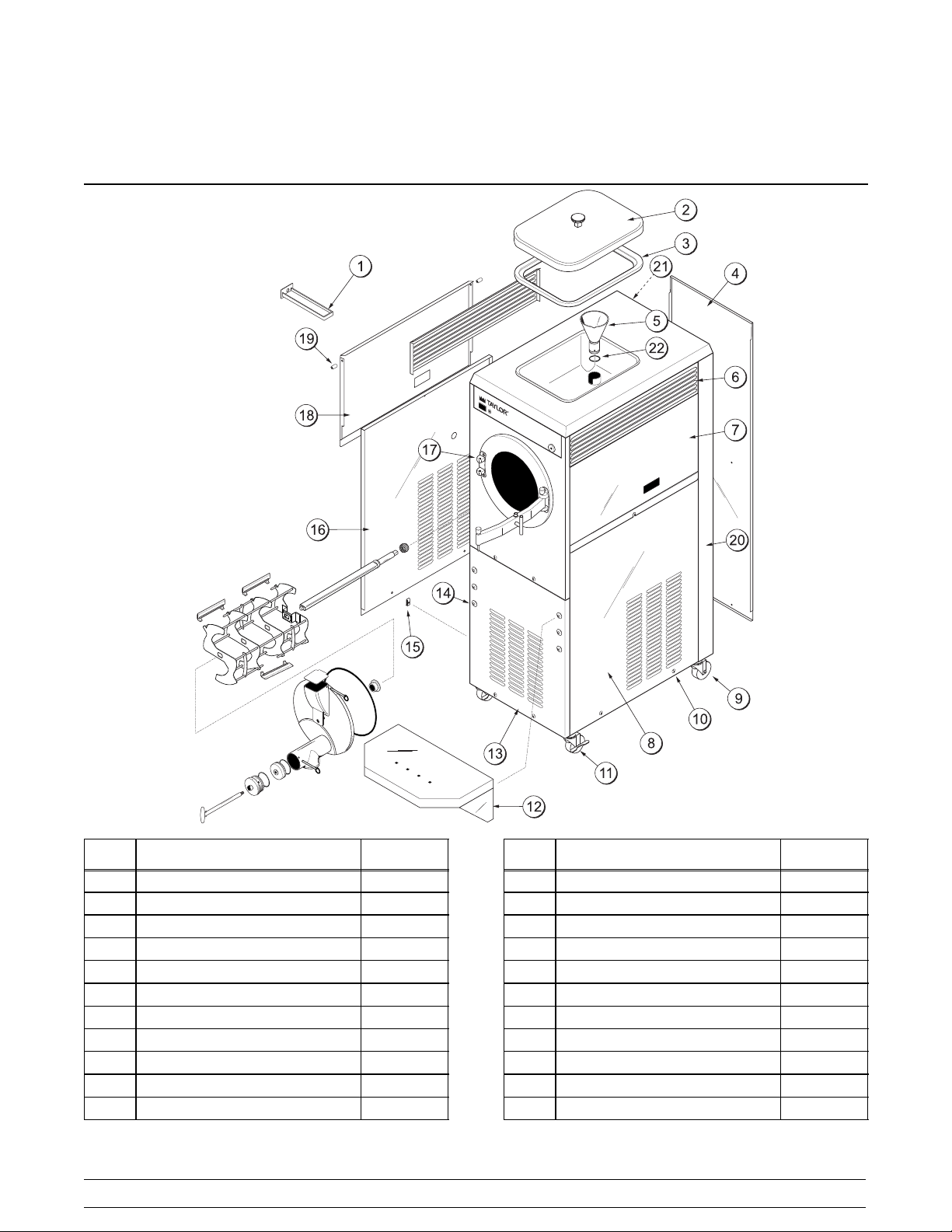
Section 4 Operator Parts Identification
ITEM DESCRIPTION PART NO.
1 PAN-DRIP 027503
2 COVER A.-HOPPER-110-220 X24778
3 GASKET-HOPPER COVER 011412
4 PANEL-REAR 031749
5 FUNNEL A.-MIX X35636
6 LOUVER-SIDEL&R 019566
7 PANEL-UPPER SIDE R. 033125
8 PANEL A.-SIDE *RIGHT* X49481
9 CASTER-SWV-3/4-10 ST. 021279
10 SCREW-1/4-20X3/8 RHM-STNLS 011694
11 CASTER-LOCKING SWIVEL 030307
Model 220 Operator Parts Identification
ITEM DESCRIPTION PART NO.
12 SHELF-DRIP TRAY 031753
13 PANEL-FRONT LOWER 049441
14 COLLAR-HOLDING 019481
15 FASTENER-CLIP 1/4-20 U-TYPE 045865
16 PANEL A.-SIDE LEFT* X49480
17 PANEL A.-FRONT X32154
18 PANEL-UPPER SIDE L. 033124
19 BUSHING-PANEL 013289
20 TRIM--REAR CORNER R. 031895
21 TRIM--REAR CORNER L. 031894
22 O--RING 1--5/8 OD X .139 W 011471
7
Page 12

Beater Door Assembly
ITEM DESCRIPTION PART NO.
1 ROD A.-DRAW X30079
2 HOLDER A.-BEARING X30078
3 O-RING-2-1/8 OD X .139W-#225 020051
4 PISTON-VALVE 030083
5 PIN-HINGE X04329
6 PIN A.-PIVOT X34737
7 DOOR A.-PARTIAL SPOUT X32938
8 CAP A.-COVER X29667
ITEM DESCRIPTION PART NO.
9 O-RING-11-3/8OD X .103W 019046
10 BEARING-FRONT 019176
11 BEATER A. X32269
12 BLADE-SCRAPER 052586
13 SHAFT-BEATER 032276
14 SEAL-DRIVE SHAFT 031316
15 SCREW A.-CROSS BAR X07233
16 BAR-CROSS 011740
8
Model 220Operator Parts Identification
Page 13

Accessories
ITEM DESCRIPTION PART NO.
1 PAIL-MIX 10 QUARTS 013163
2 BRUSH-MIXTANKBODY3”X7” 023316
3 BRUSH-DRAW VALVE 1-1/2”X3” 014753
4 BRUSH-REAR BRG 1”X2”X14” 013071
Model 220 Operator Parts Identification
ITEM DESCRIPTION PART NO.
5 LUBRICANT-TAYLOR 047518
6 SANITIZER KAY-5 125 PKTS. 041082
7 FUNNEL-PLASTIC DOOR 029670
8 PLUNGER A. X09585
9
Page 14

Section 5 Important: To the Operator
Figure 1
ITEM DESCRIPTION
1 Control Switch (Switch--Rocker)
2 Dial Light (Light--Orange--Round)
3 Temperature Control (Control--Temp.)
freezing cylinder while the control switch is in the
“AUTO” position. Always put the control switch into
the “EJECT” position when drawing product from the
freezing cylinder. As an additional safety feature, this
unit will not operate if the door is open.
Note: Never empty the contents of the
Symbol Definitions
To better communicate in the International arena, the
words on many of our operator switches and buttons
have symbols to indicate their functions. Your Taylor
equipment is designed with these International
symbols.
The following chart identifies the symbol definitions
used on the operator switches.
=COLDER
=WARMER
= TEMP (T emperature)
Control Switch
When the control switch is placed in the “AUTO”
position, the refrigeration system will operate. When
the switch is placed in the “EJECT” position, only the
beater motor will operate.
Dial Light
Located to the right of the control switch is a round dial
light. When the control switch is in the “AUTO”
position, this light will come on, indicating the
refrigeration system is operating.
Temperature Control
Located on the right front side is the temperature
control knob. Turning the adjusting knob clockwise
will decrease product temperature. Turning the
adjusting knob counterclockwise will increase
product temperature. Each quarter turn will vary the
temperature approximately two degrees.
Reset Mechanism
Located on the left side panel is the reset button. The
reset protects the beater motor from an overload
condition. Should an overload occur, the reset
mechanism will trip. To properly reset the freezer,
place the control switch in the “OFF” position. Press
the reset button firmly. Place the control switch in the
“EJECT” position and observe the freezer’s
performance. Return the control switch to the “AUTO”
position.
10
Model 220Important: To the Operator
Page 15

Section 6 Operating Procedures
The Model 220 freezer can produce all flavors of ice
cream, including those with fruits and nuts. Thefreezer
is designed for filling pints, quarts or gallons to be
placed in a hardening cabinet. The unit has a 10 quart
(9.5 liter) mix hopper.
The Model 220 will produce 20 quarts (18.9 liters) of
frozen product from 10 quarts (9.5 liters) of fresh mix.
We begin our instructions at the point where we find
the parts disassembled and laid out to air dry from the
previous brush cleaning.
The following procedures will show you how to
assemble the parts into the freezer, sanitize them, and
prime the freezer with fresh mix to prepare the first
batch.
Figure 2
If you are disassembling the machine for the first time
or need information to get to this starting point in our
instructions, turn to page 21, “Disassembly” and start
there.
Assembly
MAKE SURE THE CONTROL SWITCH IS
IN THE “OFF” POSITION. Failure to follow this
instruction may result in severe personal injury from
hazardous moving parts.
Step 1
Install the driveshaft. Apply an even coat of lubricant
to the groove and shaft portion of the drive shaft. Do
not lubricate the hex end. Slide the shaft seal, small
end first, onto the shaft. Push the seal over the
shoulder and into the groove in the shaft. Apply
additional lubricant insidethe large opening of the seal.
Insert the drive shaft through the rear shell bearing,
and engage the hex end firmly into the gear box
coupling. Be certain that the drive shaft fits into the
coupling without binding.
Figure 3
Model 220 Operating Procedures
11
Page 16

Step 2
Install the beater assembly. First check the scraper
blades for any nicks or signs of wear. If the blades are
in good condition, place the rear scraper blade into the
grooves on the beater (knife edge to the outside). The
pins on the blades fit under the pins on the beater to
prevent the blades from falling off.
Figure 4
Holding the rear blade on the beater, slide the beater
assembly into the freezing cylinder over the drive shaft
until the entire blade is inside. Install the middle
scraper blade into the two middle holding pins. Slide
the beater assembly in farther and install the front
scraper blade into the two front holding pins. Slide the
beater assembly the rest of the way into the freezing
cylinder.
Step 3
Assemble the freezer door. Insert the large o--ring
into the groove on the back of the freezer door.
Figure 6
Insert the front bearinginto the holein the center on the
back of the freezer door.
Figure 5
Make sure the beater assembly is pushed all the way
to the rear of the freezing cylinder and that the end of
the beater shaft protrudes from the end of the beater
assembly. When in position, the beater will not
protrude beyond the front of the freezing cylinder.
Figure 7
Slide the o--ring into the groove on the valve piston,
and lubricate.
Figure 8
12
Model 220Operating Procedures
Page 17

Slide the o--ring into the groove on the bearing holder,
and lubricate.
Lightly lubricate the inside of the valve body in the
freezer door.
Figure 9
Lightly lubricate the draw rod, and slide the bearing
holder onto the rod, locking stem first.
Figure 10
Thread the valve piston on the endof the draw rod until
tight.
Figure 12
Insertthe draw rod assembly, valvepistonfirst, into the
valve body.
Figure 13
Turn the draw rod handle to lock the bearing holder into
place.
Figure 11
Model 220 Operating Procedures
13
Figure 14
Page 18

Turn the bearing holder so the holes are aligned with
the holes in the valve body. Secure with the keeper pin.
Figure 15
Step 4
Install the freezerdoor. Align the hole in the cross bar
with the hole in either hinge, and insert the hinge pin.
The cross bar can be assembled for either right or left
opening. Holding the freezer door firmly, position the
door onto the cross bar. Align the cross bar with the
opposite hinge and insert the remaining hinge pin.
Figure 17
Step 5
Align the holes in the cover cap assembly with the
holes on the freezer door. Secure with the keeper pin.
Figure 16
Make sure the freezer door fits securely over the
freezing cylinder. With the door seated over the front
of the freezing cylinder, install the cross bar screw
assembly in the center of the freezer door through the
cross bar. Tighten securely.
Figure 18
Step 6
Slide the rear drip tray into the hole in the left side
panel.
Figure 19
14
Model 220Operating Procedures
Page 19

Step 7
Install the shelf. Choose the level desired and align
the grooves in the back of the shelf with the holding
collars. Slide the shelf down over the holding collars of
the same height on the left and right sides.
Figure 20
Step 2
Install the o--ring on the bottom of the funnel.
Figure 22
Step 3
Lay the funnel and the hopper gasket in the bottom of
the mix hopper and pour the sanitizing solution into the
hopper.
Sanitizing
Step 1
Prepare a pail of approved 100 PPM sanitizing solution
(examples: 2--1/2 gal. [9.5 liters] of Kay--5R or 2 gal.
[7.6 liters] of Stera--SheenR). USE WARM WATER
AND FOLLOW THE MANUFACTURER’S
SPECIFICATIONS.
Figure 23
Step 4
While the solution is flowing into the freezing cylinder,
brush clean the hopper and the mix inlet hole.
Figure 21
Model 220 Operating Procedures
15
Figure 24
080911
Page 20

Figure 25
Step 5
Place the control switch in the “EJECT” position. This
will cause the sanitizing solution in the freezing
cylinder to be agitated. Allow to agitate for five
minutes.
Step 6
Place the control switch in the “OFF” position.
With an empty mix pail beneath the ejection port, turn
the draw rod handle and pull forward, opening the
ejection port. Draw off all the sanitizing solution. When
the sanitizer stops flowing from the ejection port, push
the draw rod back into the valve body and lock into
place.
Figure 27
Step 7
Assemble the hopper gasket around the top edge of
the mix hopper.
Figure 26
16
Figure 28
Model 220Operating Procedures
Page 21

Priming
Step 1
Place the funnel in the mix inlet hole at the rear of the
hopper. Turn the funnel to the right or left so that the
opening in the funnel does not align with the opening
in the mix inlet hole.
Figure 29
Step 2
Pour 10 quarts (9.5 liters) of FRESH mix into the
hopper. This should bring the mix level up to the
second graduated mark on the rear wall of the hopper.
Step 3
With the control switch in the “OFF” position, hold an
empty mix pailbeneath the ejection port. Turn the draw
rod handle and pull forward, opening the ejection port.
Figure 30
Step 4
Turn the funnel to the right or left so that the opening
in the funnel aligns with the opening in the mix inlet
hole. Mix being added will force any remaining
sanitizing solution in the freezing cylinder out into the
mix pail.
Figure 31
060425
Model 220 Operating Procedures
17
Page 22

Step 5
When full strength mix is flowing from the ejection port,
push the draw rod back into the valve body and lock
into place.
Step 6
Place the mix hopper cover in position.
Figure 34
Figure 32
Note: The funnel can be returned to its closed
position. Another measure of mix can be poured into
the hopper in readiness for the next batch while the first
batch of mix is freezing.
Figure 33
Step 7
Place the control switch in the “AUTO” position. When
the unit automatically cycles off, the light will turn off.
This light is a visual signal that the product is down to
its proper temperature. Place the control switch in the
“OFF” position.
Figure 35
18
Model 220Operating Procedures
Page 23

Step 8
To add fruits and nuts, place the control switch in the
“EJECT” position. There are two ways to add fruits
and nuts, as follows:
Fruits and nuts can be added through the mix hopper
funnel assembly. Use the plunger to press the
ingredients down into the freezing cylinder.
Fruits and nuts can also be added through the opening
in the freezer door. Install the white plastic door
funnel before using the plunger to press the
ingredients into the freezing cylinder.
Step 2
Place the cup on the scale and adjust the scale pointer
to the zero setting.
Figure 37
Step 3
Draw off one pint (1/2 liter) of product, and with a
straight edge, level off the top.
Figure 36
Note: The plastic door funnel MUST be installed
beforeusing the plunger when adding fruits andnuts
through the opening in the freezer door. Failure to
install the door funnel may result in the plunger hitting
the beater assembly and damaging the machine.
If the plunger will not be used, fruits and nuts can be
added through the freezer door without installing the
plastic door funnel.
Step 9
Thoroughly mix the added ingredients until the desired
consistency is obtained.
Overrun
With the control switch in the “EJECT” position, take
a sample of the product to determine overrun. If the
overrun is not at the desired level, leave the control
switch in the “EJECT” position to agitate the product
and blend more air into the mixture. Continue to take
samples until the desired overrun is obtained.
Step 1
Use a standard overrun scale and a one pint (1/2 liter)
measuring cup.
Figure 38
Step 4
Place the pint (1/2 liter) of product on the scale and
read the overrun directly off of the scale.
Figure 39
060425
Model 220 Operating Procedures
19
Page 24

Step 5
If the scale does not have overrun graduations, then
weigh one pint (1/2 liter) of mix before freezing. Draw
a sample pint (1/2 liter) of frozen product and level it off
with a straight edge.
Step 6
Place the pint (1/2 liter) of product on the scale and
read the weight. Divide the weight of the frozen product
into the weight of the raw mix for your percent of
increase. If the answer is 2, you have 100% overrun.
If the answer is between 1 and 2, the decimal
represents your overrun.
Example:
1.85
8.2
15.2
Raw Mix = 15.2 oz. (450 ml)
Frozen Mix = 8.2 oz. (243 ml) Overrun = 85%
Step 3
When the freezing cylinder is empty of product, close
the ejection port and place the control switch in the
“OFF” position.
Note: The shelf can be adjusted for large or small
containers. Lift upwards on the front edge of the shelf
to disengage from the holding collars; then lift away
from the freezer. Choose the desired height and slide
the shelf back down over the holding collars of the
same height on right and left sides.
Figure 40
Drawing Product
Step 1
When the desired temperature and overrun of the
product has been achieved, the product may be drawn
into packages or cans for hardening. Place the
package or can directly beneath the ejection port of the
freezer door.
Step 2
Put the control switch into the “EJECT” position and
place the container on the shelf.
Turn the draw rod handle and pullforward, opening the
ejection port. When the container is full, push the draw
rod back into the valve body and lock into place.
Closing Procedures
After the necessary batches have been prepared, the
machine should be cleaned and sanitized. The
following procedures will show you how to rinse the
freezing cylinder of mix residue, clean and sanitize,
and disassemble the parts from the freezer.
Rinsing
MAKE SURE THE CONTROL SWITCH IS
IN THE “OFF” POSITION. Failure to follow this
instruction may result in severe personal injury from
hazardous moving parts.
Step 1
Remove the hopper cover, the gasket and the funnel.
Take these parts to the sink for cleaning.
Step 2
Pour two gallons (7.6 liters) of cool, clean water into
the mix hopper. With the brushes provided, scrub the
mix hopper and the mix inlet hole.
20
Model 220Operating Procedures
Page 25

Step 3
Put the control switch into the “EJECT” position and
allow the water to agitate for approximately one
minute.
Step 4
Put the control switch into the “OFF” position. Hold a
mix pail beneath the ejection port.
Disassembly
MAKE SURE THE CONTROL SWITCH IS
IN THE “OFF” POSITION. Failure to follow this
instruction may result in severe personal injury from
hazardous moving parts.
Step 5
Turn the draw rod handle and pull toward, opening the
ejection port. When the water stops flowing from the
ejection port, push the draw rod back into the valve
body and lock into place.
Repeat these procedures until the rinse water being
drawn from the freezing cylinder is clear.
Cleaning/Sanitizing
Step 1
Prepare a pail of approved 100 PPM cleaning/sanitizing solution (examples: 2--1/2 gal. [9.5 liters] of
Kay--5R or 2 gal. [7.6 liters] of Stera--SheenR). USE
WARM WA TER AND FOLLOW THE MANUFACTURER’S SPECIFICATIONS.
Step 2
Pour the cleaning/sanitizing solution into the hopper
and allow it to flow into the freezing cylinder.
Step 3
While the solution is flowing into the freezing cylinder,
brush clean the hopper and the mix inlet hole.
Step 4
Put the control switch into the “EJECT” position. This
will cause the cleaning/sanitizing solution in the
freezing cylinder to be agitated. Allow it to agitate for
five minutes.
Step 5
Put the control switch into the “OFF” position. Hold an
empty mix pail beneath the ejection port.
Step 6
Turn the draw rod handle and pullforward, opening the
ejection port. Draw off all the sanitizing solution. When
the sanitizer stops flowing from the ejection port, push
the draw rod back into the valve body and lock into
place.
Step 1
Remove the cross bar screw assembly, the hinges,
pins, the cross bar, the freezer door, the beater
assembly, the scraper blades, and the drive shaft from
the freezing cylinder. Also remove the adjustable shelf.
Take these parts to the sink for further disassembly
and cleaning.
Step 2
Remove the rear drip tray from the side panel.
Note: If the drip tray is filled with an excessive amount
of mix, it is anindication that the drive shaft seal should
be replaced or was improperly lubricated.
Brush Cleaning
Step 1
Prepare a sink with an approved cleaning solution
(example: Kay--5R or Stera--SheenR). USE WARM
WATER AND FOLLOW THE MANUFACTURER’S
SPECIFICATIONS.
If an approved cleaner other than (example: Kay--5R
or Stera--SheenR) is used, dilute it according to the
label instructions. IMPORTANT: Follow the label
directions. Too STRONG of a solution can cause parts
damage, while too MILD of a solution will not provide
adequate cleaning. Make sure all brushes provided
with the freezer are available for brush cleaning.
Step 2
Remove the seal from the drive shaft.
Step 3
From the freezer door:
Remove the keeper pin on the valve body. Turn the
draw rod handle and pull the draw rod assembly out of
the valve body. Unscrew the valve piston and slide the
bearing holder down off the draw rod. Remove the
o--ring from the valve piston and the bearing holder.
Remove the large o--ring and the front bearing from the
back of the freezer door. Remove the keeper pin from
the cover cap assembly and remove the cover cap
assembly.
080911
Model 220 Operating Procedures
21
Page 26

Note: To remove o--rings, use a single service towel
to grasp the o--ring. Apply pressure in an upward
direction until the o--ring pops out of its groove. With
the other hand, push the top of the o--ring forward. It
will roll out of the groove and can be easily removed.
If there is more than one o--ring to be removed, always
remove the rear o--ring first. This will allow the o--ring
to slide over the forward rings without falling into the
open grooves.
Take these parts to the sink for cleaning,
Step 4
Thoroughly brush clean all disassembled parts in the
cleaning solution, making sure all lubricant andmix film
is removed. Place all the cleaned parts on a clean dry
surface to air dry overnight.
Step 5
Return to the freezer with a small amount of cleaning
solution. With the black bristle brush, brush clean the
rear shell bearing at the back of the freezing cylinder.
Figure 41
Step 6
Wipe clean the shelf and all exterior surfaces of the
freezer.
22
Model 220Operating Procedures
Page 27

Section 7 Important: Operator Checklist
During Cleaning and Sanitizing
Cleaning and sanitizing schedules are governed by
your State or local regulatory agencies and must be
followed accordingly. The following check points
should be stressed during the cleaning and sanitizing
operations.
We recommend that after the necessary
batches have been prepared for the day, the
machine be cleaned and sanitized.
ALWAYS FOLLOW LOCAL HEALTH CODES.
T roubleshooting Bacterial Count
j 1. Thoroughly clean and sanitize the machine
regularly, including complete disassembly and
brush cleaning.
j 2. Use all brushes supplied for thorough cleaning.
The brushes are specially designed to reach all
mix passageways.
Regular Maintenance Checks
j 1. Replace scraper blades that are nicked or
damaged. Before installing the beater, be
certain that the scraper blades are properly
attached.
j 2. Check the rear shell bearing for signs of wear
(excessive mix leakage in rear drip pan) and be
certain it is properly cleaned.
j 3. Using a screwdriver and cloth towel, keep the
rear shell bearing and the female hex drive
socket clean and free of lubricant and mix
deposits.
j 4. Dispose of o--rings and seals if they are worn,
torn, or fit too loosely, and replace with new
ones.
j 5. Follow all lubricating procedures as outlined in
“Assembly”.
j 3. Use the white bristle brush to clean the mix inlet
hole which extends from the mix hopper down
to the rear of the freezing cylinder.
j 4. Use the black bristle brush to thoroughly clean
the rear shell bearing located at the rear of the
freezing cylinder. Be sure there is a generous
amount of cleaning solution on the brush.
j 5. Properly prepare the cleaning/sanitizing
solution. Read and follow the label directions
carefully. Too strong of a solution may damage
the parts and too weak of a solution will not do
an adequate job of cleaning and sanitizing.
j 6. The temperature of the liquid mix should be
below 40_F. (4 . 4 _C.).
j 7. The temperature of finished product to be
placed in a hardening cabinet should be
between 23_ and 25_F(--5.0_ to -- 3.9_C).
Model 220 Important: Operator Checklist
j 6. If your machine is air cooled, check the
condenser for accumulation of dirt and lint. Dirty
condensers will reduce the efficiency and
capacity of the machine. Condensers should be
cleaned monthly with a soft brush.
Note: For machines equipped with an air filter,
it will be necessary to vacuum clean the filters
on a monthly schedule.
Never use screwdrivers or other metal
probes to clean between the fins.
j 7. On water cooled units, check the water lines for
kinks or leaks. Kinks can occur when the
machine is moved back and forth for cleaning or
maintenance purposes. Deteriorated or
cracked water lines should be replaced only by
an authorized Taylor technician.
051101
23
Page 28

Winter Storage
If the place of business is to be closed during the winter
months, it is important to protect the freezer by
following certain precautions, particularly if the
building is subject to freezing conditions.
Disconnect the freezer from the main power source to
prevent possible electrical damage.
On water cooled freezers, disconnect the water
supply. Relieve pressure on the spring in the water
valve. Use air pressure on the outlet side to blow out
any water remaining in the condenser. This is
extremely important. Failure to follow this procedure
may cause severe and costly damage to the
refrigeration system.
Your local Taylor Distributor can perform this service
for you.
Wrap detachable parts of the freezer such as the
beater, blades, drive shaft, and freezer door. Place
these parts in a protected, dry place. Rubber trim parts
and gaskets can be protected by wrapping them with
moisture--proof paper. All parts should be thoroughly
cleaned of dried mix or lubrication which attract mice
and other vermin.
080221
24
Model 220Important: Operator Checklist
Page 29

Section 8 Troubleshooting Guide
PROBLEM PROBABLE CAUSE REMEDY PA G E
REF.
1. Unit will not run in the
“AUTO” position.
2. Product is not freezing. a. Dirty condensers. a. Clean condensers
3. Drive shaft is stuck. a. Rounded corners on shaft,
a. Unit is unplugged. a. Plug in wall receptacle. -- --
b. Circuit breaker is off. b. Turn the breaker on. -- --
c. Unit is off on reset. c. Place control switch in the
“OFF” position. Press
reset button firmly. Place
control switch in the
“EJECT” position and
observe freezer’s
performance. Resume
normal operation.
regularly.
b. The control switch is not in
the “AUTO” position.
c. On water cooled units,
inadequate water supply.
drive socket, or both.
b. Place the control switch in
the “AUTO” position.
c. Check to be sure the
water is turned on. Check
hoses for leaks or kinks.
a. Replace the drive shaft,
drive socket, or both. Do
not lubricate the hex end
of the drive shaft. Contact
a service technician.
10
23
18
23
-- --
4. Walls of freezer cylinder
are scored.
5. Excessive mix leakage in
the rear drip tray.
6. Buzzer does not sound
when the freezer cycles
off.
(Note: the buzzer is an
optional feature.)
Model 220 Troubleshooting Guide
a. Scraper blades were
improperly installed.
a. Drive shaft seal is worn or
missing.
b. Inadequate lubrication of
drive shaft seal.
c. Rear shell bearing is worn. c. Contact a service
d. The wrong type of
lubricant is being used.
a. Buzzer is malfunctioning. a. Contact a service
25
a. Install them properly. 12
a. Install or replace the seal. 11
b. Lubricate properly. 11
technician.
d. Use Taylor Lube. -- --
technician.
-- --
-- --
Page 30

PROBLEM PROBABLE CAUSE REMEDY PA G E
REF.
7. Overrun is too low. a. The temperature control is
set too cold.
b. Not enough air is blended
into the product.
c. Improper priming
procedures.
8. Overrun is too high. a. Not enough mix is in the
freezing cylinder when
priming the machine.
b. The temperature control is
set too warm.
c. Left in “EJECT” position
too long after drawing
some product out to place
in hardening cabinet.
a. Adjust it accordingly. 10
b. Place the control switch in
the “EJECT” position to
blend in more air.
Continue blending until the
desired overrun is
achieved.
c. Follow priming
procedures.
a. Follow priming
procedures.
b. Adjust accordingly. 10
c. After drawing out the first
portion, place the control
switch in the “OFF”
position. Return to freezer
to draw out more product,
place control switch in the
“EJECT” position.
19
17
17
-- --
26
Model 220Troubleshooting Guide
Page 31

Section 9 Parts Replacement Schedule
PART DESCRIPTION EVERY 3
Front Bearing X 1
Scraper Blades X 3
Drive Shaft Seal X 1
Funnel O--Ring X 1
Freezer Door O--Ring X 1
Bearing Holder and Valve Piston
O--Ring
Black Bristle Brush, 1” x 2” Inspect &
White Bristle Brush, 1--1/2” x 2” Inspect &
White Bristle Brush, 3” x 7” Inspect &
MONTHS
X 2
EVERY 4
MONTHS
EVERY 6
MONTHS
Replace if
Necessary
Replace if
Necessary
Replace if
Necessary
ANNUALLY QTY.
Minimum 1
Minimum 1
Minimum 1
Model 220 Parts Replacement Schedule
27
Page 32

Section 10 Parts List
UPDATE
REMARKS PARTS
CLASS
QTY. WARR.
NUMBER
DESCRIPTION PART
048741- 1 512 Prior to J9066689 145
BOOT-CAPACITOR INSULATING 031314 1 000
CAPACITOR-RUN- 10 UF/370V 033047 1 103
HOUSING A.-W/WHEEL X30160 1 103
MOTOR-BLOWER-208/230V 50/60 HZ 046536-27 1 103
BRUSH-DRAW VALVE1-1/2”OD X 3” 014753 1 000
BRUSH-MIX PUMPBODY-3”X7”WHITE 023316 1 000
BRUSH-REAR BRG 1IN.DX2IN.LGX14 013071 1 000
BUZZER 022758-27 1 103
CAP-RUBBER MOUNT 011844 2 103
+CAPACITOR-RUN- 40MF/440 Volt 036049 1 103 208-230/60/1
+CAPACITOR-START-189-227UF/330V 033044-1 1 103 208-230/60/1
+RELAY-START-COMPRESSOR 053473 1 103 208-230/60/1
CASTER-LOCKING SWIVEL 3 IN. 030307 2 103 FRONT
CASTER-SWV-3/4-10 ST.3IN WHL 021279 2 103 REAR
COLLAR-HOLDING 019481 6 103
COMPRESSOR CS27K3E-PFV-238 053465- 1 512 J9066689/Up 145
COMPRESSOR L63A183BBCA - BRISTOL
HP62 -- J5083472/Up
BAR-CROSS *220* 011740 1 103
+PIN A.-CROSSBAR HINGE X04329 2 103
BEARING-REAR SHELL *NICK.PLATE 031324 1 000
+GUIDE-DRIP SEAL 028992 1 000
+NUT-BRASS BEARING 028991 1 000
+WASHER-BEARING LOCK 012864 1 000
BEATER A.-NEW STYLE 220* X32269 1 103
+BLADE-SCRAPER *220* PLASTIC 052586 3 000 (OLD METAL - X07892)
BELT-V-4L400 007590 2 000
BLOCK-TERMINAL 2P-L1,L2 039422 1 103 208-230/60/1
BLOCK-TERMINAL 3P-L1,L2,L3 039423 1 103 208-230/60/3
BLOWER A. X47833-27 1 103
+ Available Separately
Parts List Model 220
28
+CAPACITOR-RUN- 35UF/440V 048132 1 103 208-230/60/1
Page 33

UPDATE
REMARKSWARR.
CLASS
QTY.PART
NUMBER
DESCRIPTION PARTS
+CAPACITOR-START-216-259UF/330V 048908 1 103 208-230/60/1
+RELAY-START-COMPRESSOR 048909 1 103 208-230/60/1
CONDENSER-AC-12LX18HX4.3-5ROW 019558 1 103
CONTROL-TEMP -15F TO 40F 019747 1 103
+ Available Separately
+KNOB-TEMPCONTROL 013731 1 103
COUPLING-DRIVE 3/4 HEX X 1-7/8 012721 1 103
+SCREW-5/16-18 X 5/16 ALLEN SET 042511 2 000
COVER A.-HOPPER-110-220 X24778-SER 1 103
+GASKET-HOPPER COVER-10 QT 011412 1 000
KNOB-MIX COVER 025429 1 103
DECAL-CLEAN INST.-BATCH 030582 1 000
DECAL-DEC-TAYLOR 021872 1 000
DECAL-TROUBLESHOOTING 038374 1 000
DIAGRAM-WIRING *110-220* 030385 1 000
DOOR A.-PARTIAL *220* SPOUT X32938 1 103 W/CHUTE & INTERLOCK
+BEARING-FRONT *110-220* 019176 1 000
+CAP A.-COVER *220* X29667 1 103
+HOLDER A.-BEARING *121 W/SPOUT X30078 1 103
+O-RING-5/8 OD X.139W 026020 1 000
+O-RING-11-3/8 OD X .103W 019046 1 000
+O-RING-2-1/8 OD X .139W-#225 020051 2 000
+PIN A.-PIVOT X34737 2 103
+PISTON-VALVE *121 W/SPOUT* 030083 1 103
+ROD A.-DRAW *121 W/SPOUT* X30079 1 103
DRYER-FILTER 3/8 X 3/8SOL HP62 049154 1 000
FUNNEL A.-MIX *220* X35636 1 103
+O-RING-1-5/8 OD X .139W 018564 1 000 REPLACES 011471
FUNNEL-PLASTIC DOOR 029670 1 000
GEAR A.*REDUCER 021286 1 212
GUIDE A.-DRIP PAN X28863 1 103
HINGE-CROSSBAR 007296 2 103
HOOD *220* 032157 1 103
KIT A.-TUNE UP*220*NEW* X33081 1 000
Model 220 Parts List
29
Page 34

UPDATE
REMARKSWARR.
CLASS
QTY.PART
NUMBER
DESCRIPTION PARTS
BEARING-FRONT *110-220* 019176 1 000
O-RING-1-5/8 OD X .139W 018564 1 000 MIX FUNNEL
O-RING-11-3/8 OD X .103W 019046 1 000
O-RING-2-1/8 OD X .139W-#225 020051 2 000
+ Available Separately
SEAL-DRIVE SHAFT 031316 1 000
TOOL-O-RING REMOVAL-FREEZER 048260-WHT 1 000
LABEL-DOOR CAUTION 032749 1 000
LABEL-WARM/COLD-INT'L SYMBOL 013749 1 000
LABEL-WARNING-COVER 051433 5 000
LIGHT-ORANGE-ROUND 017450 1 103
LOUVER-SIDE 019566 2 103
LUBRICANT-TAYLOR 4 OZ. 047518 1 000
MAN-OPER 110/220 028763-M 1 000
MOTOR-1.5 HP 021522- 1 212
PAIL-MIX 10 QT. 013163 1 000
PAN-DRIP 11-5/8 LONG 027503 1 103
PANEL A.-FRONT *220* X32154 1 103
PANEL A.-SIDE *220*LEFT*HP62 X49480 1 103
PANEL A.-SIDE *220*RIGHT*HP62 X49481 1 103
PANEL-FRONT LOWER *220*HP62 049441 1 103
PANEL-REAR *121-26-31-220* 031749 1 103
PANEL-UPPER SIDE L. *220* 033124 1 103
PANEL-UPPER SIDE R. *220* 033125 1 103
PIN A.-CROSSBAR HINGE X04329 2 103
PLATE-DEC-110-220* 033027 1 103
PLUG-DRIP TRAYHOLE 029595 1 103
PLUNGER A. *110-20-1-220* X09585 1 103
PULLEY-2AK32 X .626-.627 016251 1 103 BEATER MOTOR
PULLEY-2AK64-5/8 BORE 039695 1 103 GEAR
RECEIVER A. *220*AC*HP62 X49437 1 103 ACCUMULATOR
RELAY-3 POLE-20A-208/240 50/60 012725-33 1 103
ROD-SWITCH *131* 031730 1 103
SANITIZER KAY-5 125 PACKETS 041082 1 000
Parts List Model 220
30
Page 35

UPDATE
REMARKSWARR.
CLASS
QTY.PART
NUMBER
DESCRIPTION PARTS
+SEAL-DRIVE SHAFT 031316 1 000
SCREW A.-CROSSBAR X07233 1 103
SHAFT-BEATER *220* 032276 1 103
SHELF-DRIP TRAY*121-26-31-220* 031753 1 103
+ Available Separately
SHELL A.-INSULATED *220* X34861 1 512
ARM A.-SWITCH*121-6 131-32* X31728 1 103
BRACKET-SWITCH DOOR 015335 1 103
E-RING 3/16 .335 O.D. 049178 1 000
INSULATOR-ARMITE-4 HOLE 012992 1 000
PIN-PIVOT 015478 1 103
SPRING-RETURN 015342 1 103
SWITCH-LEVER-SPDT-15A-125-480V 009367 1 103
STARTER-1 PHASE-4.5 TO 7 A 041950-27K 1 103 208-230/50-60/1
STARTER-3 PHASE-3 TO 5 AMP 041950-33J 1 B 208-230/60/3
SWITCH A.-DRAW *121-6 131-32* X31727-SER 1 103
SWITCH-PRESSURE 440 PSI-SOLDER 048230 1 103
SWITCH-ROCKER-DPDTON-OFF-ON 014237 1 103
+BRACKET-ROCKER SWITCH 020820 1 103
+CARD-SWITCH INDICATOR 027910 1 000
TRIM-REAR CORNER L. *110-21-26 031894 1 103
TRIM-REAR CORNER R. *110-21-26 031895 1 103
TUBE-CAPILLARY .021ID X 18 FT 035438 1 103
VALVE-ACCESS 1/4FL X 3/8SOLDER 043232 1 103
VALVE-ACCESS-1/4 MFLX1/4S-90 047016 1 103
VALVE-EXP-THERMO-3/8S X 1/2S 049425 1 103
+ARM-DRAW A. *110-220* X23158 1 103
+BALL-RUBBER 1/2 DIA 022594 1 103
+CAP-STEM *110-220* 022593 1 103
+PIN A.-PIVOT X34737 1 103
+PIN-COTTERLESSHITCH-1-1/2”L 019849 1 103
DOOR A.-PARTIAL *220 KNIFE X29666-SP 1 103
KNIFE DOOR
Model 220 Parts List
31
Page 36

UPDATE
REMARKSWARR.
CLASS
QTY.PART
NUMBER
DESCRIPTION PARTS
+PLATE-SEAL *220* 022783 1 103
+STEM *220* 024842 1 103
ADAPTOR-3/8MP X 1/2BARB-BR 011021 2 103
WATER COOLED
+ Available Separately
BLOWER-100 CFM 012796-27 1 103
BRACKET-MOUNTING-WATER VALVE 038777 1 103
CONDENSER-WC-COAX 047540 1 103
GUARD-BLOWER 022505 1 103
HOSE-RUBBER 1/2”ID X 7/8”OD 020901-24 1 000 BULK - R50200
HOSE-RUBBER 1/2”ID X 7/8”OD 020901-28 1 000 BULK - R50200
RECEIVER A. *220*WC*HP62 X49438 1 103 ACCUMULATOR
SWITCH-PRESSURE 350 PSI-SOLDER 048231 1 103
VALVE-WATER 3/8 REG/HEAD PRESS 046686 1 103
BLOCK-TERMINAL 3P-L1,L2,L3 039423 1 103 220-240/50/3
50Hz
+CAPACITOR-RUN- 35UF/440V 048132 1 103
+RELAY-START-COMPRESSOR 049240 1 103
+CAPACITOR-START-270-324UF/330V 049655 1 103
BLOCK-TERMINAL 4P-L1,L2,L3,N 039424 1 103 220-240/380-415/50/3
BLOCK-TERMINAL-7 POLE GREEN 024156 1 103 220-240/380-415/50/3
COMPRESSOR L63A183DBDA 048741-33 1 512 220-240/50/3
COMPRESSOR L63A183BBKA 048741-40 1 512 220-240/50/1
COMPRESSOR L63A183DBEA 048741-58 1 512 220-240/380-415/50/3
DIAGRAM-WIRING *110-220* 030385-33 1 000 220-240/50/3
DIAGRAM-WIRING *110-220* 030385-34G 1 000 220-240/50/1
DIAGRAM-WIRING *110-220* 030385-62 1 000 220-240/380-415/50/3
MOTOR-1.5 HP 021522-34 1 212 220-240/50/1
MOTOR-1.5 HP 021522-35 1 212 220-240/380-415/50/3
PANEL-FRONT LOWER *220*HP62 049441-SP 1 103 220-240/380-415/50/3
PULLEY-2AW375 X .625-.6265 031221 1 103 BEATER MOTOR - 1 & 3 PHASE
STARTER-3 PH 1.4 TO 2.3A 5HP 041950-33G 1 103 220-240/380-415/50/3
Parts List Model 220
32
Page 37

Model 220
030385
3/10
Page 38

Model 220
030385
Inset
3/10
Page 39

Model 220
030385--33
3/10
Page 40

Model 220
030385--62
3/10
 Loading...