

Page 1

Models 150, 152, 162, & 168
Taylormate
Soft Serve Freezers
Operating Instructions
028749-M
6/98
Page 2

Complete this page for quick reference when service is required:
Taylor Distributor:
Address:
Phone:
Service:
Parts:
Date of Installation:
Information found on data plate:
Model Number:
Serial Number:
Electrical Specs: Voltage Cycle
Phase
Maximum Fuse Size: Amps
Minimum Wire Ampacity: Amps
Part Number:
E June, 1998 Taylor
All rights reserved.
028749--M
Taylor Company
The word Taylor and the Crown design
are registered trademarks in the United States
of America and certain other countries.
a division of Carrier Commercial Refrigeration, Inc.
750 N. Blackhawk Blvd.
Rockton, IL 61072
Page 3

Table of Contents
______________________________________________________________________________
Section 1 To the Installer 1............................................
Air Cooled Units 1.......................................................
Electrical Hook-Up Installation for 60 Cycle, 1 Phase,
Supplied With Cord and Plug 1...........................................
Electrical Connections for Models Without Cord and Plug Supplied 1..........
Section 2 To the Operator 2...........................................
Compressor Warranty Disclaimer 2.......................................
Section 3 Safety 3....................................................
Section 4 Operator Parts Identification 4...............................
Model 150 4............................................................
Model 152 5............................................................
Model 162 6............................................................
Model 168 7............................................................
Models 150 & 152 Door Assembly 8.......................................
Models 162 & 168 Door Assembly 9.......................................
Section 5 Important: To the Operator 10.................................
Push-Button Switch 10....................................................
Power Switch 10.........................................................
Temperature Control 10...................................................
Air Tube 11.............................................................
Taylor Quality Control 11..................................................
Indicator Light -- “Mix Low” 11.............................................
Mix Refrigeration Switch 11...............................................
Separate Hopper Refrigeration (SHR) 12...................................
Cylinder Temperature Retention (CTR) 12...................................
Syrup Rail 12............................................................
Section 6 Operating Procedures 13.....................................
Assembly 14............................................................
Sanitizing 17............................................................
Priming 19..............................................................
Closing Procedure 20....................................................
Draining Product From the Freezing Cylinder 20.............................
Rinsing 20..............................................................
Cleaning 20.............................................................
Disassembly 21..........................................................
Brush Cleaning 21.......................................................
Table of Contents Models 150, 152, 162, 168
Page 4

Section 7 Important: Operator Checklist 22..............................
During Cleaning and Sanitizing 22.........................................
Troubleshooting Bacterial Count 22........................................
Regular Maintenance Checks 22...........................................
Winter Storage 23........................................................
Section 8 Troubleshooting Guide 24....................................
Section 9 Parts Replacement Schedule 27...............................
Section 10 Parts List 28.................................................
Wiring Diagrams 37......................................................
Note: Continuing research results in steady improvements; therefore, info rmation
in this manual is subject to change without notice.
Models 150, 152, 162, 168 Table of Contents
Page 5
Section 1 To the Installer
Air Cooled Units
The models 150 and 152 require a minimum of 6” (152
mm) of clearance around both sides. Install the skirt
provided on the right side of the unit and place the back
of the unit against a wall to prevent recirculation of
warm air. The model 162 requires 6” (152 mm) on all
sides and the skirt installed on the rear of the unit. The
model 168 requires 3” (76 mm) on all sides and the
skirt installed on the rear of the unit. Minimum air
clearances must be met to assure adequate air flow for
optimum performance.
These machines are designed for indoor use only.
DO NOT install the machines in an area where
a water jet could be used. Failure to follow this
instruction may result in serious electrical shock.
Electrical Hook-Up Installation For
60 Cycle, 1 Phase, Supplied With Cord and Plug
This equipment is supplied with a 3-wire cord and
grounding type plug for connection to a single phase,
60 cycle, branch circuit supply. This unit must be
plugged into a properly grounded receptacle. The cord
and plug provided for 115/60/1, is 20 amp; therefore
the wall outlet must also be 20 amp. Check the data
label, located on the side panel, for electrical
specifications.
FOLLOW YOUR LOCAL ELECTRICAL CODES!
Electrical Connections For
Models Without Cord and Plug Supplied
Each freezer requires one power supply for each data
label. Check the data label(s) on the freezer for fuse,
circuit ampacity and electrical specifications. Refer to
the wiring diagram provided inside of the control box,
for proper power connections.
In the United States, this equipment is intended to be
installed in accordance with the National Electrical
Code (NEC), ANSI/NFPA 70--1987. The purpose of
the NEC code is the practical safeguarding of persons
and property from hazards arising from the use of
electricity. This code contains provisions considered
necessary for safety. Compliance therewith and
proper maintenance will result in an installation
essentially free from hazard! In all other areas of the
world, equipment should be installed in accordance
with the existing local codes. Please contact your local
authorities.
Stationary appliances which are not equipped with a
power cord and a plug or other device to disconnect
the appliance from the power source must have an
all--pole disconnecting device with a contact gap of at
least 3 mm installed in the external installation.
Permanent wiring may be employed if required by local
codes. Instructions for conversion to permanent wiring
are as follows:
1. Be sure the freezer is electrically disconnected.
2. Remove the appropriate panel and locate the
small electrical box at the base of the freezer.
3. Remove the factory-installed cord and strain
relief bushing.
4. Route incoming permanent wiring through 7/8”
(22 mm) hole in base pan.
5. Connect two power supply leads. Attach ground
(earth) wire to the grounding lug inside the
electrical box.
6. Be sure the unit is properly grounded before
applying power.
Models 150, 152, 162, 168 To the Installer
properly grounded! Failure to do so can result in
severe personal injury from electrical shock!
Beater rotation must be clockwise as viewed looking
into the freezing cylinder.
Note: The following procedures should be performed
by an authorized service technician.
To correct rotation on a three-phase unit, interchange
any two incoming power supply lines at freezer main
terminal block only. T o correct rotation on a
single-phase unit, change the leads inside the beater
motor. (Follow diagram printed on motor.)
Electrical connections are made directly to the
terminal block provided in the splice box, mounted on
the base pan on each side of the model 168, and
located in the splice boxes mounted mid-level on the
frame channel on the sides of the model 162.
1
CAUTION: This equipment must be
031030
Page 6

Section 2 To the Operator
The freezer you have purchased has been careeru3n4s50818
050818
2
Models 150, 152, 162, 168To th e Operator
Page 7
Section 3 Safety
We at Taylor Company are concerned about the safety
of the operator when he or she comes in contact with
the freezer and its parts. Taylor has gone to extreme
efforts to design and manufacture built-in safety
features to protect both you and the servicetechnician.
As an example, warning labels have been attached to
the freezer to further point out safety precautions to the
operator.
IMPORTANT! Failure to adhere to the
following safety precautions may result in severe
personal injury. Failure to comply with these warnings
may damage the machine and its components.
Component damage will result in part replacement
expense and service repair expense.
To Operate Safely:
S DO NOT allow untrained personnel to
operate this machine.
S DO NOT put objects or fingers in door
spout.
S DO NOT operate the freezer unless all
service panels and access doors are
restrained with screws.
S DO NOT remove the freezer door or beater
assembly unless the control switches are in
the “OFF” position.
Failure to follow these instructions may result in severe
personal injury from hazardous moving parts.
DO NOT operate the freezer without reading
this operator’s manual. Failure to follow this instruction
may result in equipment damage, poor freezer
performance, health hazards, or personal injury.
S DO NOT operate the freezer unless it is
properly grounded.
S DO NOT operate the freezer with larger
fuses than specified on the freezer data
label.
S DO NOT attempt any repairs unless the
main power supply to the freezer has been
disconnected.
Failure to follow these instructions may result in
electrocution. Contact your local authorized Taylor
Distributor for service.
DO NOT use a water jet to clean or rinse the
freezer. Failure to follow these instructions may result
in serious electrical shock.
031030
Models 150, 152, 162, 168 Safety
3
Page 8

Section 4 Operator Parts Identification
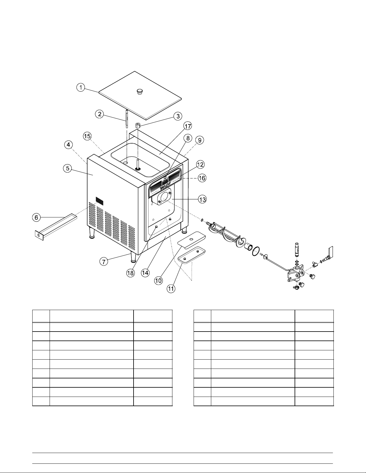
Model 150
4
Models 150, 152, 162, 168Operator Parts Identification
Page 9
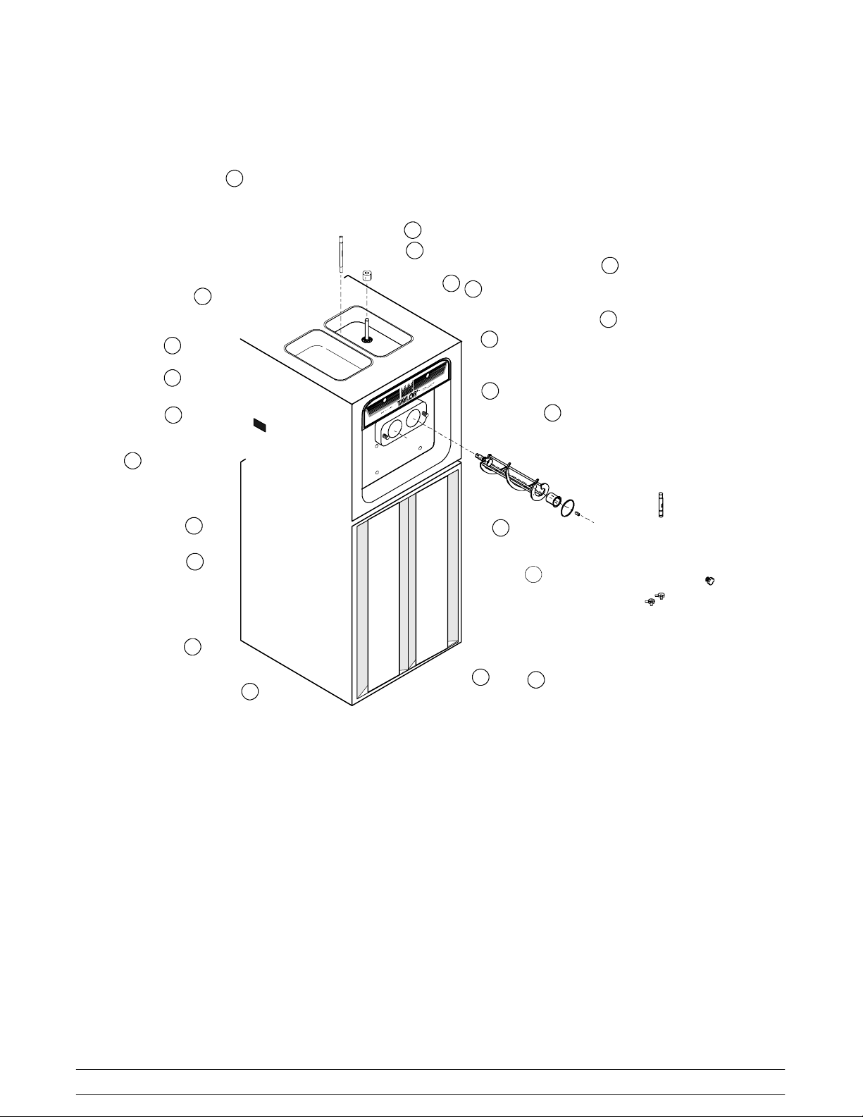
Model 152
Item Description Part No.
1 Hopper Cover Assembly X48690
2 Feed Tube 025061
3 Float A.-Mix Level X39690
4 Back Panel 025868-SS
5 Left Side Panel 028591-SS
6 Drip Pan 027503
7 Leg-Plastic 024755
8 Mix Low Light 039708
9 Right Side Panel 025867-SS
Models 150, 152, 162, 168 Operator Parts Identification
Item Description Part No.
10 Splash Shield 025063
11 Drip Tray 025062
12 Decorative Decal 047667
13 Panel A.-Front X25036
14 Trim-Front 025862-SS
15 Trim-Top Back 025866
16 Plate-Decorative 041034-SS
17 Hood Assembly X49065
18 Holder-Drip Tray 035866
5
Page 10
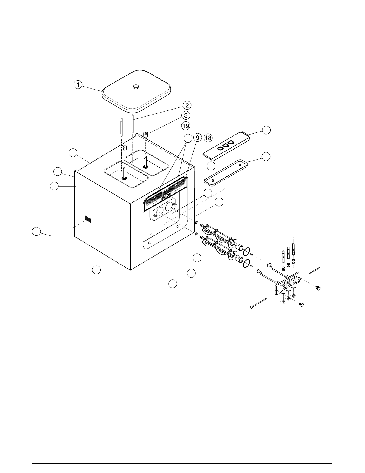
Model 162
6
Models 150, 152, 162, 168Operator Parts Identification
Page 11
Model 168
Models 150, 152, 162, 168 Operator Parts Identification
7
Page 12

Models 150 & 152 Door Assembly
8
Models 150, 152, 162, 168Operator Parts Identification
Page 13
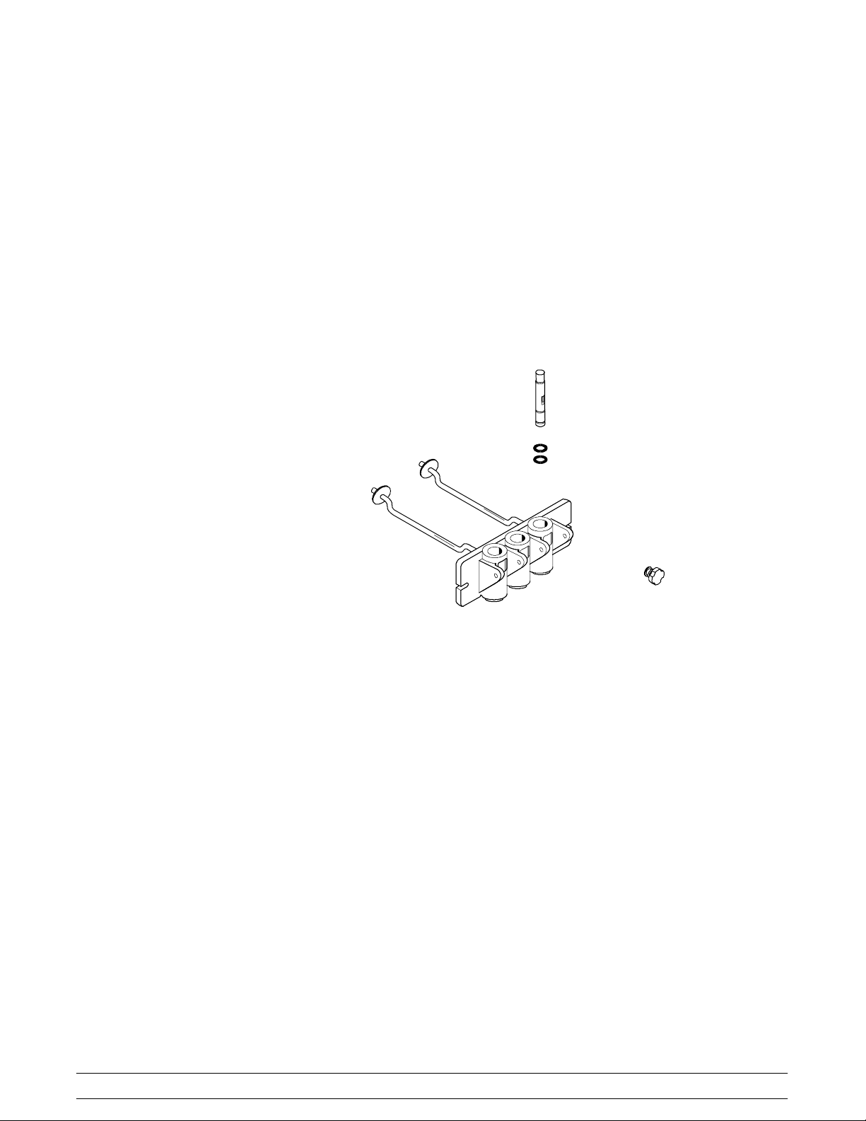
Models 162 & 168 Door Assembly
Models 150, 152, 162, 168 Operator Parts Identification
9
Page 14
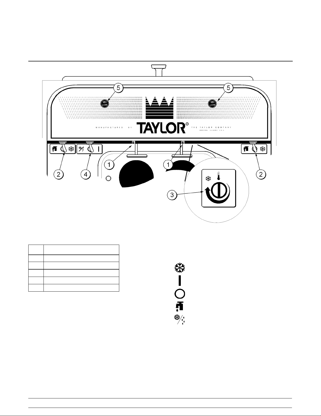
Section 5 Important: To the Operator
Item
1 Push Button Switch
2 Power Switch
3 Temperature Control
4 Mix Refrigeration Switch
5 Indicator Lights -- “Mix Low”
Description
Symbol Definitions
To better communicate in the International arena, the
words on many of our operator switches and buttons
have symbols to indicate their functions. Your Taylor
equipment is designed with these International
symbols.
Figure 1
The following chart identifies the symbol definitions
used on the operator switches.
= The ON/AUTO keypad.
= The ON keypad.
= The OFF keypad.
= The WASH keypad.
= The STANDBY keypad.
10
Models 150, 152, 162, 168Important: To the Operator
Page 15
Push-Button Switch
If an overload condition occurs, the freezer will
automatically stop operating. To properly reset the
freezer, place the toggle switch in the “OFF” position.
Wait two or three minutes; then press the push-button
switch. Place the power switch in the “WASH” position
and observe the freezer’s performance; place the
power switch in the “AUTO” position.
Note: If the freezer is unplugged from the wall
receptacle, it will be necessary to press the
push-button switch for the freezer to operate once
power is re-established.
Figure 2
Power Switch
The center position is “OFF”. The left position is
“WASH” which activates the beater motor only. The
right position is “AUTO”, which activates the beater
motor and the refrigeration system.
Temperature Control
The Models 150 and 152 use a temperature control to
monitor the product in the freezing cylinder. Turning
the adjusting knob clockwise will decrease the
product temperature. Turning the adjusting knob
counterclockwise will increase the temperature.
Each quarter of a turn will vary the temperature
approximately two degrees. DO NOT set the
temperature control colder than 18_F (-8_C). Should
you set the temperature colder than 18_F (-8_C),
premature failure of the belts and of the beater motor
may occur.
Note: During “AUTO” operation, the orifice end of the
tube should be inserted in the hole in the hopper.
Taylor Quality Control
The Models 162 and 168 use a solid state control
called the T.Q.C. The purposeof this solid state control
is to sense the viscosity (thickness) of the product in
the freezing cylinder. With the power switch in the
“AUTO”position, the T.Q.C. will automatically keep the
mix in the freezing cylinder at the proper viscosity and
ready for serving.
The Models 150 and 152 are available with the T.Q.C.
as an option.
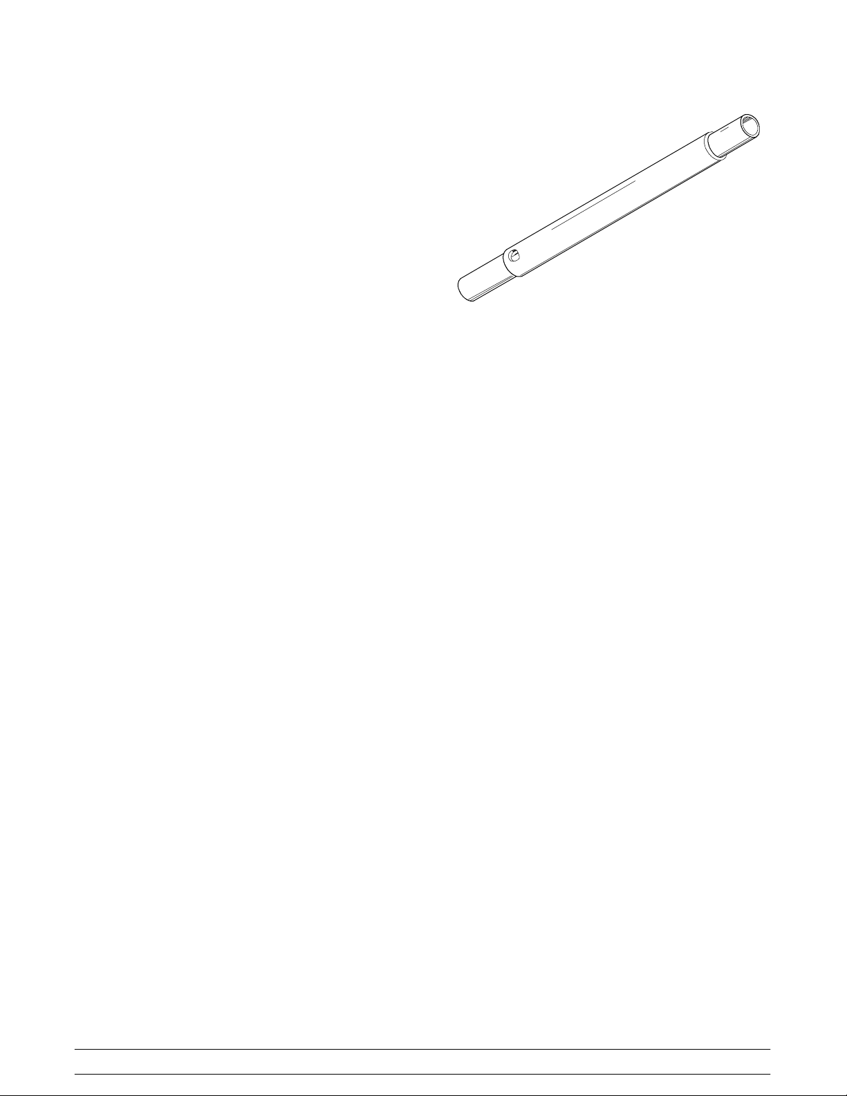
Air Tube
The models 150, 152, 162 and 168 are called upon to
handle a large variety of products (i.e., soft serve,
yogurts, Italian ices, sherbets, etc.). Thus, the
consistency of the mix you use will vary. The air tube
meters a combination of mix and air into the freezing
cylinder. If not enough mix enters the freezing cylinder,
a freeze-up may occur, which will cause eventual
damage to the beater. Depending upon the product
being run, you may wish to contact your local
authorized Taylor Distributor to make a slight
adjustment in the air tube.
Models 150, 152, 162, 168 Important: To the Operator
Indicator Light -- “Mix Low”
A mix level indicating light is located at the front of the
machine. When the light is on, it indicates that the mix
hopper has a low supply of mix and should be refilled
as soon as possible. Always maintain at least 2” (5.1
cm) of mix in the hopper. If you neglect to add mix, a
freeze-up may occur. This will cause eventual damage
to the beater assembly and to the freezer door.
11
Page 16

Mix Refrigeration Switch
The mix refrigeration switch is located under the
control channel and is used for several purposes:
1. For the unit to operate in the “AUTO” mode, the
mix refrigeration switch must be “ON”.
2. For the separate hopper refrigeration system to
operate, the mix refrigeration switch must be in
the “ON” or the “STANDBY” position.
3. For the cylinder temperature retention system
to operate, the power switch must be in the
“AUTO” position and the mix refrigeration
switch must be in the “STANDBY” position.
Cylinder Temperature Retention
(CTR)
To maintain a good quality product during long “No
Sale” periods, it will be necessary to warm the product
in the freezing cylinder to approximately 35_ to 40_F
(1.7_ to 4.4_C). This will prevent overbeating and
product breakdown. The CTR is used in conjunction
with the SHR to insure that the mix in the freezing
cylinder is refrigerated during the “STANDBY” mode of
operation.
To operate the “STANDBY” mode of operation:
Place the power switch in the “AUTO” position and the
mix refrigeration switch in the “STANDBY” position.
With sanitized hands, remove the air tube. Turn it over
and place the end without the hole into the mix inlet
hole.
To resume normal operation:
Separate Hopper Refrigeration
(SHR)
This feature incorporates the use of a separate small
refrigeration system to chill (on a limited basis) and to
maintain the mix in the hopper to under 40_F(4.4_C)
and assures bacterial control. To activate this system,
place the power switch in the “AUTO” position and the
mix refrigeration switch in the “AUTO” position. To operate this system in the “STANDBY” mode, place the
power switch in the “AUTO” position and the mix refrigeration switch in the “STANDBY” position.
Leave the power switch in the “AUTO” position and
place the mix refrigeration switch in the “AUTO”
position. When the unit cycles off, the product in the
freezing cylinder will be the correct viscosity. With
sanitized hands, remove the air tube. Turn it over and
place the end with the hole into the mix inlet hole.
Syrup Rail
These units are available with an optional syrup rail to
store cold toppings for sundaes.
12
Models 150, 152, 162, 168Important: To the Operator
Page 17

Section 6 Operating Procedures
The Model 150 has been selected to illustrate the
pictured step-by-step operating procedures. All
models in this manual are similar. They each have a
1.5 quart (1.4 liter) capacity freezing cylinder. The mix
flows by gravity from the hopper to the freezing
cylinder through an air tube.
The Model 150 is a console model with a single spout
door.
The Model 152 is a counter model with a single spout
door.
The Model 162 is a counter model and the Model 168
is a console model. Both have three spout doors. Two
individual flavors are available from the end spouts,
and an equal combination of both is dispensed through
the center spout to create a twist effect.
For the Model 162 and 168, duplicate the procedures
where they apply for the second freezing cylinder.
We begin our instructions at the point where we enter
the store in the morning and find the parts
disassembled and laid out to air dry from the previous
night’s cleaning.
These opening procedures will show you how to
assemble these parts into the freezer, sanitize them,
and prime the freezer with fresh mix in preparation to
serve your first portion.
Figure 4
Figure 5
Figure 6
If you are disassembling the machine for the first time
or need information to get to the starting point in our
instructions, turn to page 21, “Disassembly”, and start
Figure 3
Models 150, 152, 162, 168 Operating Procedures
there.
13
Page 18

Assembly
Note: When lubricating parts, use an approved food
grade lubricant (example: Taylor Lube).
Step 1
Install the beater assembly. Slide the small, thick o-ring
into the groove on the drive shaft of the beater
assembly. Apply an even coat of Taylor Lube to the
o-ring and the shaft.
DO NOT LUBRICATE THE HEX END.
Step 2
Assemble the freezer door. Place the large o-ring(s)
into the groove(s) on the back of the freezer door and
lubricate with Taylor Lube.
Figure 9
Slide the front bearing(s) over the baffle rod(s) so the
flanged edge is against the door. Place the white
plastic guide bearing(s) on the end of the baffle rod(s).
Figure 7
Insert the beater assembly through the rear shell
bearing at the back of the freezing cylinder and engage
the hex end firmly into the female socket. When
properly seated, the beater will not protrude beyond
the front of the freezing cylinder.
Figure 8
Repeat this step for the second freezing cylinder on
Models 162/168.
DO NOT LUBRICATE THE FRONT BEARING(S) OR
THE GUIDE BEARING(S).
Figure 10
Step 3
Slide the slotted portion of the handscrews into the
slots in the freezer door.
060421
14
Models 150, 152, 162, 168Operating Procedures
Page 19

Step 4
Install the freezer door. With both hands, hold the sides
of the freezer door and insert the baffle rod(s) into the
center of the beater assembly(ies). The white guide
bearing(s) must fit securely in the hole(s) of the drive
shaft(s). Finger-tighten the handscrews equally to
insure that the door is snug. Do not over-tighten.
Note: The freezer door is in the correct position when
the door spout is on the bottom.
Step 5
Install the draw valve(s). Slide the two o-rings into the
grooves on the draw valve(s) and lubricate with Taylor
Lube.
Models 150, 152, 162, 168 Operating Procedures
15
Page 20

Step 6
Install the draw valve handle. Insert the valve lifter arm
through the slotted opening in the draw valve and align
the other end with the cross holes of the freezer door.
Hint: The valve lifter arm may be aligned with the left
or right cross hole. The draw valve handle will be
placed through the opposite cross hole of the valve
lifter arm.
Figure 15
Slide the o-ring into the groove on the draw valve
handle and lubricate with Taylor Lube.
Figure 17
Figure 16
Insert the draw valve handle through the opposite
cross hole and into the opening of the valve lifter arm.
Hint: The draw valve handle can be assembled at
varied vertical positions. Choose an angle which is
comfortable for you. The draw valve must be raised
completely when the draw valve handle is down.
Figure 18
Note: For Models 162/168, slide the o-ring onto each
pivot pin and lubricate with Taylor Lube.
Figure 19
16
Models 150, 152, 162, 168Operating Procedures
Page 21

Note: Models 162/168 have three draw handles.
Slide the tip of the draw handle into the slot of the draw
valve, starting from the right. Slide the short pivot pin
through the far right draw handle. Slide the long pivot
pin through the far left and middle draw handles.
Figure 20
Step 7
Snap the design cap(s) over the bottom of the freezer
door spout(s).
Sanitizing
Step 1
Prepare one gallon (3.8 liters) of an approved 100
PPM sanitizing solution (example: Kay-5t). USE
WARM WATER AND FOLLOW THE MANUFACTURER’S SPECIFICATIONS.
Step 2
Pour one gallon (3.8 liters) of sanitizing solution into
the hopper and allow it to flow into the freezing cylinder.
Step 3
While the solution is flowing into the freezing cylinder,
brush-clean the mix hopper, mix level float stem, mix
level float, mix inlet hole, and air tube.
Figure 21
Step 8
Lay the air tube(s) in the bottom of the mix hopper(s).
Figure 22
Models 150, 152, 162, 168 Operating Procedures
17
Page 22

18
Models 150, 152, 162, 168Operating Procedures
Page 23

Priming
Prime the machine as close as possible to the time of
first product draw.
Step 1
With a pail beneath the door spout, raise the draw
valve. Fill the mix hopper with fresh mix. (Maximum
hopper capacity is 8 quarts [7.6 liters].) Allow the mix
to flow into the freezing cylinder. This will force out any
remaining sanitizing solution. When full strength mix is
flowing from the door spout, lower the draw valve.
Note: Use only FRESH mix when priming the
freezer.
031030
Models 150, 152, 162, 168 Operating Procedures
19
Page 24

Step 6
Slide the rear drip pan into the hole in the side panel.
ALWAYS FOLLOW LOCAL HEALTH CODES.
Repeat Steps 1 through 3 for the second freezing
cylinder on Models 162/168.
Rinsing
Step 1
Pour one gallon (3.8 liters) of cool, clean water into the
mix hopper. With the brushes provided, scrub the mix
hopper, the mix level float stem and the mix inlet hole.
Figure 33
Closing Procedure
To disassemble the Models 150/152/162/168, the
following items will be needed:
S Two cleaning pails
S Sanitized stainless steel rerun can with lid
S Necessary brushes (provided with freezer)
S Cleaner
S Single service towels
Draining Product From the
Freezing Cylinder
Step 1
Place the power switch in the “OFF” position as far
ahead of cleaning time as possible. This will allow
frozen product to soften for easier cleaning.
Step 2
Lift the hopper cover. Remove the air tube and mix
level float. Take them to the sink for cleaning.
Step 3
With a sanitized pail beneath the door spout, place the
power switch in the “WASH” position and raise the
draw valve. When all the product stops flowing from
the door spout, lower the draw valve and place the
power switch in the “OFF” position. If local health
codes permit, empty the rerun into a sanitized
stainless steel rerun can. Cover the container and
place it in the walk-in cooler.
Step 2
With a pail beneath the door spout, place the power
switch in the “WASH” position and raise the draw
valve. Drain all the rinse water from the freezing
cylinder. When the rinse water stops flowing from the
door spout, lower the draw valve and place the power
switch in the “OFF” position.
Repeat this procedure until the rinse water being
drawn from the freezing cylinder is clear.
Repeat Steps 1 and 2 for the second freezing cylinder
on Models 162/168.
Cleaning
Step 1
Prepare one gallon (3.8 liters) of an approved cleaning
solution (example: Kay-5t). USE WARM WATER
AND FOLLOW THE MANUFACTURER’S SPECIFICATIONS.
Step 2
Pour the one gallon (3.8 liters) of cleaning solution into
the mix hopper and allow it to flow into the freezing
cylinder.
Step 3
While the solution is flowing into the freezing cylinder,
brush-clean the mix hopper, mix level float stem and
mix inlet hole.
Step 4
Place the power switch in the “WASH” position. This
will cause the cleaning solution in the freezing cylinder
to agitate.
Step 5
Place an empty pail beneath the door spout and raise
the draw valve. Draw off all the cleaning solution.
20
Models 150, 152, 162, 168Operating Procedures
Page 25

When the solution stops flowing from the door spout,
lower the draw valve and place the power switch in the
“OFF” position.
Repeat Steps 1 through 5 for the other side of the
freezer on Models 162/168.
Step 3
From the freezer door, remove the design cap, draw
valve handle, valve lifter arm, and draw valve. Remove
all o-rings.
Models 162/168: From the freezer door, remove
design caps, pivot pins, draw handles, draw valves,
and the center draw valve. Remove all o-rings.
Disassembly
Step 1
BE SURE THE POWER SWITCH IS IN THE “OFF”
POSITION.
Step 2
Remove the handscrews and the freezer door.
Remove the beater assembly(ies) from the freezing
cylinder(s) and take these parts to the sink for
cleaning.
Step 3
Remove the front drip tray and the splash shield from
the freezer. Take them to the sink for cleaning.
Brush Cleaning
Step 1
Prepare a sink with an approved cleaning solution.
USE WARM WAT ER AND FOLLOW THE MANUFACTURER’S SPECIFICATIONS.
IMPORTANT: Follow label directions, as too
STRONG of a solution can cause parts damage, while
too MILD of a solution will not provide adequate
cleaning.) Make sure all brushes provided with the
freezer are available for brush cleaning.
Step 4
Remove the large o-ring(s), front bearing(s), and guide
bearing(s) from the back of the freezer door.
Step 5
Return to the freezer with a small amount of cleaning
solution. With the black bristle brush, brush clean the
rear shell bearing(s) at the back of the freezing
cylinder(s).
Step 2
Remove the o-ring(s) from the drive shaft(s) of the
beater assembly(ies).
Note: To remove the o-rings, use a single service
towel to grasp the o-ring. Apply pressure in an upward
direction until the o-ring pops out of its groove. With the
other hand, push the top of the o-ring forward, and it
will roll out of the groove and can be easily removed.
If there is more than one o-ring to be removed, always
remove the rear o-ring first. This will allow the o-ring to
slide over the forward rings without falling into the open
grooves.
Models 150, 152, 162, 168 Operating Procedures
21
Page 26

Section 7 Important: Operator Checklist
During Cleaning and Sanitizing
ALWAYS FOLLOW LOCAL HEALTH CODES.
Cleaning and sanitizing schedules are governed
by federal, state, or local regulatory agencies,
and must be followed accordingly. If the unit
has a “Standby mode”, it must not be used in
lieu of proper cleaning and sanitizing
procedures and frequencies set forth by the
ruling health authority. The following check
points should be stressed during the cleaning
and sanitizing operations.
CLEANING AND SANITIZING MUST BE
PERFORMED DAILY.
T roubleshooting Bacterial Count
j 1. Thoroughly clean and sanitize the machine
regularly, including complete disassembly and
brush cleaning.
j 2. Use all brushes supplied for thorough cleaning.
The brushes are specially designed to reach all
mix passageways.
j 3. Use the smaller, white bristle brush to clean the
mix inlet hole which extends from the mix
hopper down to the rear of the freezing cylinder.
j 4. Use the black bristle brush to thoroughly clean
the rear shell bearing located at the rear of the
freezing cylinder. Be sure to have a generous
amount of cleaning solution on the brush.
j 5. IF LOCAL HEALTH CODES PERMIT THE
USE OF RERUN, make sure the mix rerun is
stored in a sanitized, covered stainless steel
container and is used the following day. DO
NOT prime the machine with rerun. When using
rerun, skim off the foam and discard. Mix the
rerun with fresh mix in a ratio of 50/50 during the
day’s operation.
j 6. On a designated day of the week, run the mix as
low as feasible and discard after closing. This
will break the rerun cycle and reduce the
possibility of high bacteria and coliform counts.
j 7. Properly prepare the cleaning and sanitizing
solutions. Read and follow label directions
carefully. Too strong of a solution may damage
the parts and too weak of a solution will not do
an adequate job of cleaning or sanitizing.
j 8. The temperature of the mix in the mix hopper
and walk-in cooler should be below 40_F.
(4.4_C.).
Regular Maintenance Checks
j 1. Check the rear shell bearing for signs of wear
(excessive mix leakage in rear drip pan) and be
certain it is properly cleaned.
j 2. Using a screwdriver and cloth towel, keep the
rear shell bearing and the female hex drive
socket clean and free of lubricant and mix
deposits.
j 3. Dispose of o-rings or seals if they are worn, torn,
or fit too loosely , and replace with new ones.
j 4. Follow all lubricating procedures as outlined in
“Assembly”.
080107
22
Models 150, 152, 162, 168Important: Operator Checklist
Page 27

j 5. If your machine is air cooled, check the
condenser for an accumulation of dirt and lint.
A dirty condenser will reduce the efficiency and
capacity of the machine. Condensers should be
cleaned monthly with a soft brush. Never use
screwdrivers or other metal probes to clean
between the fins. Failure to comply may result
in electrocution.
Note: For machines equipped with an air filter,
it will be necessary to vacuum clean the filters
on a monthly schedule.
j 6. If your machine is equipped with an auxiliary
refrigeration system, check the condenser for
accumulation of dirt and lint. A dirty condenser
will reduce the refrigeration capacity of the mix
hopper. Condensers must be cleaned monthly
with a soft brush. Never use screwdrivers or
other metal probes to clean between the fins.
Failure to comply may result in electrocution.
Winter Storage
If the place of business is to be closed during the winter
months, it is important to protect the freezer by
following certain precautions, particularly if the
building is subject to freezing conditions.
Disconnect the freezer from the main power source to
prevent possible electrical damage.
On water cooled freezers, disconnect the water
supply. Relieve pressure on the spring in the water
valve. Use air pressure on the outlet side to blow out
any water remaining in the condenser, and then add a
liberal amount of permanent type auto anti-freeze.
This is extremely important. Failure to follow this
procedure may cause severe and costly damage to the
refrigeration system.
Your local Taylor distributor can perform this service for
you.
j 7. If your machine is water cooled, check the
water lines for kinks or leaks. Kinks can occur
when the machine is moved back and forth for
cleaning or maintenance purposes.
Deteriorated or cracked water lines should be
replaced only by an authorized Taylor
mechanic.
Wrap detachable parts of the freezer such as the
beater assembly and freezer door, and place them in
a protected dry place. Rubber trim parts and gaskets
can be protected by wrapping them with
moisture-proof paper. All parts should be thoroughly
cleaned of dried mix or lubrication accumulations
which attract mice and other vermin.
051215
Models 150, 152, 162, 168 Important: Operator Checklist
23
Page 28

Section 8 Troubleshooting Guide
PROBLEM PROBABLE CAUSE REMEDY PAG E
REF.
1. No product being
dispensed.
2. The machine will not
operate in the “AUTO”
mode.
3. The product is too stiff. a. The temperature control
a. The power switch is in the
“OFF” position.
b. The mix level is
inadequate in the mix
hopper.
c. The beater motor
overloaded.
d. The unit is unplugged at
the wall receptacle.
e. The circuit breaker is
tripped or the fuse is
blown.
f. The freezer door is
incorrectly assembled.
g. Product is being drawn off
in excess of the freezer’s
capacity.
a. The unit is unplugged. a. Plug in the power cord;
b. The refrigeration system is
not activated.
c. The circuit breaker is
tripped, or the fuse is
blown.
d. The beater motor
overloaded, causing a loss
of power to the power
switch.
or the T.Q.C. is set too
cold.
a. Place the power switch in
the “AUTO” position.
b. Fill the mix hopper with
mix.
c. Reset the freezer.
d. Plug in the power cord.
Press the push-button
switch.
e. Place the circuit breaker in
the “ON” position, or
replace the fuse. Press
the push-button switch.
f. See “Operating
Procedures” for proper
installation.
g. Stop drawing product and
allow the unit to recover.
press the push-button
switch.
b. On T.Q.C. units,
momentarily raise the
draw switch to activate the
refrigeration system.
c. Place the circuit breaker in
the “ON” position, or
replace the fuse. Press
the push-button switch.
d. Reset the freezer.
a. Adjust the temperature
control. Do not set the
temperature colder than
18_F(--8_C). If T.Q.C.,
contact service technician.
19
19
11
11
11
14
---
11
19
11
11
11
24
Models 150, 152, 162, 168Troubleshooting Guide
Page 29

PROBLEM PROBABLE CAUSE REMEDY PAG E
REF.
4. The product is too soft. a. The temperature control
or the T.Q.C. is set too
warm.
b. The air tube is not
installed.
c. Out-drawing the freezer’s
capacity.
5. The freezing cylinder walls
are scored.
a. Operating freezer without
the front bearing on the
freezer door.
b. The gear unit or the direct
drive is out of alignment.
6. Excessive leakage in rear
drip pan.
a. A worn or defective o-ring
is on the beater drive
shaft.
b. The rear shell bearing is
worn.
c. Incorrect lubricant was
used.
d. Inadequate lubrication of
beater drive shaft.
7. The draw valve is leaking. a. Incorrect lubricant was
used.
b. Worn or defective o-rings
are on the draw valve.
c. Inadequate lubrication of
draw valve.
8. Product is not feeding into
the freezing cylinder.
a. The mix level is
inadequate in the mix
hopper.
b. The mix inlet hole is
frozen.
a. Adjust the temperature
control. If T.Q.C., contact
service technician.
b. Install the air tube in the
mix inlet hole at the
bottom of the mix hopper.
c. Two 4 oz. (113.4 gram)
servings in one minute.
a. Install the front bearing on
the freezer door.
b. Contact service
technician.
a. Replace o-rings every 3
months.
b. Contact service
technician.
c. Use food grade lubricant
(example: Taylor Lube).
d. Lubricate the beater drive
shaft properly.
a. Use food grade lubricant
(example: Taylor Lube).
b. Replace o-rings every 3
months.
c. Lubricate the draw valve
properly.
a. Fill the mix hopper with
mix.
b. Contact service
technician.
11
19
---
14
---
27
---
14
14
15
27
15
19
11
Models 150, 152, 162, 168 Troubleshooting Guide
25
Page 30

PROBLEM PROBABLE CAUSE REMEDY PAG E
REF.
9. The unit goes out on
overload excessively.
10. Models 162 and 168:
Mix from one freezing
cylinder bleeds over to the
second cylinder.
a. There are too many
appliances plugged into
the circuit.
b. An extension cord has
been placed between the
power cord and the wall
receptacle.
a. The center draw valve
seal is worn, or is
improperly lubricated.
a. A separate 20 amp.
circuit is needed for the
freezer to operate
properly.
b. If the extension cord is
used, it must match the
power cord in size of
circuit ampacity.
a. Lubricate properly and
replace seal every 3
months.
---
---
15 / 27
26
Models 150, 152, 162, 168Troubleshooting Guide
Page 31

Section 9 Parts Replacement Schedule
PART DESCRIPTION EVERY 3
MONTHS
Beater Drive Shaft O-Ring X 1 2
Freezer Door O-Ring X 1 2
Freezer Door Front Bearing X 1 2
Freezer Door Guide Bearing X 1 2
Draw Valve O-Ring X 2 4
Draw Valve Handle O-Ring X 1 --
Center Draw Valve Seal X -- 1
Pivot Pin O-Ring X -- 2
Black Bristle Brush, 1” x 2” Inspect & Replace
Double Ended Brush Inspect & Replace
White Bristle Brush, 1” x 2” Inspect & Replace
EVERY 6
MONTHS
if Necessary
if Necessary
if Necessary
ANNUALLY QTY.
150/152 162/168
Minimum 1 1
Minimum 1 1
Minimum 1 1
White Bristle Brush, 3” x 7” Inspect & Replace
if Necessary
Minimum 1 1
Models 150, 152, 162, 168 Parts Replacement Schedule
27
Page 32

Section 10 Parts List
UPDATE
REMARKS PARTS
WARR.
CLASS
168
QTY.
162
152
150
DESCRIPTION PART
QTY.
QTY.
QTY.
NUMBER
BEARING--FRONT 023262 1 1 2 2 000
BEARING--GUIDE 014496 1 1 2 2 000
BEARING--REAR SHELL *150--52-- 68* 023648 1 1 2 2 000
+ NUT-- REAR BEARING *150--52-- 68* 023647 1 1 2 2 000
+ TAB--BEARING LOCK *150-- 2--68* 025027 1 1 2 2 000
BEARING--UNIT REAR 024764 1 103
BEATER A. *150--2--162--168* X24689 1 1 2 2 103
+ O-- RING-- 13/16 OD X .139W 021278 1 1 2 2 000
BELT--AX23 041137 2 000
BELT--POLY V--280J10 025776 1 000
BELT--POLY V--580J10 025551 1 000
BELT--POLY V--460J10 028182 2 000
BLOCK--TERMINAL 2P 039422 1 1 103
BLOCK--TERMINAL 5 POLE 024329 1 4 103
BLOCK--TERMINAL 7 POLE 025156 1 103 115-60-1
BRUSH--DOUBLE ENDED--PUMP&FEED T 013072 1 1 1 1 000
BRUSH--DRAW VALVE 1”ODX2”X17”L 013073 1 1 1 1 000
BRUSH--MIX PUMP BODY--3”X7”WHITE 023316 1 1 1 1 000
BRUSH--REAR BRG 1IN.DX2IN.LGX14 013071 1 1 1 1 000
CAP-- DESIGN --1.010”ID--6 POINT 014218 1 1 3 3 000
CASTER--RIGID 3 IN. WHL 012226 2 2 103 REAR
CASTER--SWIVEL 3 IN. WHEEL 012227 2 2 103 FRONT
COMPRESSOR AKA9462ZXA--AK172AT 049302-- 1 512 MAIN
+ CAPACITOR-- RUN-- 25UF/370VAC 023739 1 103 115-60-1
+ CAPACITOR-- START-- 72--88UF/250V 039557--27 1 103 115-60-1
+ RELAY--START-- COMPRESSOR 045432--12 1 103 115-60-1
+ CAPACITOR-- RUN-- 15UF/370V 027087 1 230-60-1
+ CAPACITOR-- START-- 72--88UF/330V 039567 1 230-60-1
+ RELAY--START-- COMPRESSOR 048150 1 230-60-1
COMPRESSOR AJB7461JXA-- AJ556BT 047607-- 1 512 MAIN HP81
+ CAPACITOR-- RUN-- 15UF/370V 027087 1 103 115-60-1
+ Available Separately
Parts List Models 150, 152, 162, 168
28
+ CAPACITOR-- START--340-- 408UF/165V 047608 1 103 115-60-1
Page 33

UPDATE
REMARKSWARR.
CLASS
168
QTY.
162
QTY.
152
QTY.
150
QTY.
PART
NUMBER
DESCRIPTION PARTS
KNOB--MIX COVER 025429 1 1 1 1 103
+ RELAY--START-- COMPRESSOR 047609 1 103 115-60-1
+ CAPACITOR-- RUN-- 15UF/370V 027087 1 103 230-60-1
+ CAPACITOR-- START--161-- 193UF/250V 031790 1 103 230-60-1
+ RELAY--START-- COMPRESSOR 031789 1 103 230-60-1
COMPRESSOR AKA9462ZXD--AK172ET 049302-- 2 2 512 MAIN
+ CAPACITOR-- RUN-- 25UF/370VAC 023739 2 2 103 115-60-1
+ CAPACITOR-- START-- 72--88UF/250V 039557--27 2 2 103 115-60-1
+ RELAY--START-- COMPRESSOR 045432--12 2 2 103 115-60-1
+ CAPACITOR-- RUN-- 15UF/370V 027087 2 2 103 230-60-1
+ CAPACITOR--START-- 72-- 88UF/330 039567 2 2 103 230-60-1
+ RELAY--START-- COMPRESSOR 048150 2 2 103 230-60-1
COMPRESSOR--TL2.5F--R134A 047701-- 1 1 1 512 SHR
+ RELAY--START-- COMPRESSOR 027714--12 1 1 1 103 115-60-1
+ RELAY--START-- COMPRESSOR--TL3G 047702-- 27 1 1 1 103 230-60-1
+ CAPACITOR-- START--60UF--220/275V 047703 1 1 1 103 230-60-1
CONDENSER--AC--12LX14HX1.87T 3RW 046556 1 1 103
CONDENSER--AC--7X6X1.25-- 2 ROW 027155 1 1 1 103 SHR
CONDENSER-- AC--9HX24WX2.5T--4 ROW 047146 1 103
CONDENSER--AC--15LX14HX2.57-- 4R 047255 1 103
CONTROL-- TEMP. 028914 2 2 2 103 SHR & STANDBY
CONTROL A.--TEMPERATURE X14383 1 103 HP81
+ BRACKET--RANCO *150--68* 025683 1 103
+ KNOB-- TEMPERATURE CONTROL 013731 1 103
CONTROL-- VISCOSITY--WATT X37260SER1 1 2 2 103 115 VOLT
CONTROL-- VISCOSITY--WATT X37260SER2 1 2 2 103 230 VOLT
CORD--POWER 025340-- 1 1 103
COVER A.-- HOPPER *M150--152 X48690 1 1 103
+ KNOB--MIX COVER 025429 1 1 1 103
COVER A.-- HOPPER *162-- 168* X37963 1 1 103 INCLUDES KNOB
DAMPER A.-- FOR USE ON 25W ONLY X20320 1 103
DECAL--CLEAN INST.--HOPPER 019029 1 1 1 1 000
DECAL-- DEC-- TAYLOR 150/152 047667 1 1 000
+ Available Separately
Models 150, 152, 162, 168 Parts List
29
Page 34

UPDATE
REMARKSWARR.
CLASS
168
QTY.
162
QTY.
152
QTY.
150
QTY.
PART
NUMBER
DESCRIPTION PARTS
DECAL-- DEC-- TAYLOR 162/168 047666 1 1 000
DECAL-- MIX REF. STANDBY OFF --ON 022177 1 1 1 000
DECAL-- TROUBLESHOOTING 038374 1 1 1 1 000
DECAL-- WARNING *PANEL* 036529 3 3 3 000
DECAL-- WASH--OFF-- AUTO 014502 1 1 2 2 000
ARM--VALVE LIFTER 024761 1 1 103
HANDLE-- DRAW 024762 1 1 103
O-- RING-- 2--3/4 OD X .139W 019998 1 1 000
O-- RING-- 3/4 OD X .103W 015835 1 1 000
O-- RING-- 7/8 OD X .103W 014402 2 2 000
VALVE--DRAW *150-- 2* 024763 1 1 103
HANDLE-- DRAW VALVE 030564 3 3 103
O-- RING-- 2--3/4 OD X .139W 019998 2 2 000
O-- RING-- 5/16 OD X .070W 016272 2 2 000
PIN A.--PIVOT--LONG X38538 1 1 103
PIN A.--PIVOT--SHORT X38539 1 1 103
SEAL--DRIVE SHAFT 030930 1 1 000
VALVE--DRAW *150-- 2* 024763 2 2 103
VALVE--DRAW --CENTER 031164 1 1 103
DECAL-- WARM-- COLD 013749 1 000 HP81
DIAGRAM-- WIRING *150* 050416-- 1 000
DIAGRAM-- WIRING *150* 047514 1 000 HP81
DIAGRAM-- WIRING 050205-- 1 000
DOOR A.--1 SPOUT-- 1.5 QT X38959-- SER 1 1 103
DOOR A.--3 SPOUT X30753-- SER 1 1 103
DRYER--CAP. TUBE .026 ID X 11FT 048894 1 000 SHR
DRYER-- CAP. TUBE-- HP62/R134A 047699 1 1 000 SHR
DRYER-- CAP. TUBE-- HP62/R134A 048255 1 1 000 SHR 115-60-1 ONLY
DRYER-- FILTER--HP62--3/8 X 1/4S 048901 1 2 2 000
DRYER--FILTER 1/4 X 1/4 SOLDER 041099 1 000 HP81
FLOAT A.--MIX LEVEL *142* X39690 1 1 2 2 103
GASKET--HOPPER COVER--8QT 037042 1 1 000
GEAR--REDUCER 025770 1 2 2 212
+ Available Separately
Parts List Models 150, 152, 162, 168
30
Page 35

UPDATE
REMARKSWARR.
CLASS
168
QTY.
162
QTY.
152
QTY.
150
QTY.
PART
NUMBER
DESCRIPTION PARTS
GUARD-- SWITCH *150-- 2* 025496 1 1 103
GUARD--POWER & DANFOSS SWITCH 035548 1 1 103
GUIDEA.--DRIPPAN X28593 1 103
HARNESS A.-- WIRE *150*162*LQSOL X50224 1 103
HOLDER-- DRIP TRAY*150--2--68-- 756M 035866 2 2 2 2 103
HOOD A. *150* X49063 1 103
HOOD A. *152* X49065 1 103
HOOD A. *162* X35918 1 103
HOOD A. *168* X34846 1 103
INSERT-- FRONT PANEL *168* 030773--SS 1 103
LABEL--CAUTION GROUND CORD UNIT 032165 1 000
LABEL--DOOR CAUTION 032749 1 000
LABEL--MIX COOLING ADJ. 020217 1 1 1 000
LABEL--MOVING PARTS WARNING 024315 6 3 000
LABEL--STD BY BARREL TEMP ADJ 029092 2 2 000
LEG--4”-- 3/8--16 STUD--PLASTIC 024755 4 103
LEG--4” SS--W/ORING 013458 4 103
LIGHT-- MIX LOW--AMBER ROUND-- 12V 039707 1 1 1 103
CAP-- DESIGN --1.010”ID--6 POINT 014218 1 1 000
O-- RING-- 7/8 OD X .103W 014402 2 2 000
BEARING--GUIDE 014496 1 1 000
O-- RING-- 3/4 OD X .103W 015835 1 1 000
O-- RING-- 2--3/4 OD X .139W 019998 1 1 000
O-- RING-- 13/16 OD X .139W 021278 1 1 000
BEARING--FRONT 023262 1 1 000
TOOL--CLEANING 0-- RING REMOVAL 048260 1 1 000
BEARING--FRONT 023262 2 2 000
BEARING--GUIDE 014496 2 2 000
CAP-- DESIGN --1.010”ID--6 POINT 014218 3 3 000
LIGHT-- MIX LOW--AMBER ROUND-- 24V 039708 1 103 HP81
LUBRICANT--T AYLOR 4 OZ. 047518 1 1 1 1 000
KIT A.--TUNE UP*150--152* X25802 1 1 000
KIT A.--TUNE UP*162--168* X31167 1 1 000
+ Available Separately
Models 150, 152, 162, 168 Parts List
31
Page 36

UPDATE
REMARKSWARR.
CLASS
168
QTY.
162
QTY.
152
QTY.
150
QTY.
PART
NUMBER
DESCRIPTION PARTS
O-- RING-- 13/16 OD X .139W 021278 2 2 000
O-- RING-- 2--3/4 OD X .139W 019998 2 2 000
O-- RING-- 5/16 OD X .070W 016272 2 2 000
O-- RING-- 7/8 OD X .103W 014402 4 4 000
SEAL--VALVE 030930 1 1 000
TOOL--CLEANING 0-- RING REMOVAL 048260 1 1 000
MAN-- OPER 150/152/162/168 028749--M 1 1 1 1 000
MOTOR-- 1/2 HP 024839-- 1 1 2 2 212
MOTOR-- FAN 17W/60HZ 2900RPM-- CCW 027309-- 1 1 1 103 SHR
MOTOR-- FAN 35W-- 40”LEADS 027817-- 1 1 103
+ FAN--4 BLADE 11 ” PULL 30DEG CW 028405 1 103
+ FAN--4 BLADE 11 ” PUSH 30DEG CW 027818 1 103
MOTOR-- FAN--25W 015184-- 2 103
+ FAN--5 BLADE 8” PUSH 37 DEG CCW 047231 2 103
MOTOR-- FAN 120 W 208/230V 60H 041401--27 1 103
+ BOOT--CAPACITOR INSULATING 031324 1 000
+ CAPACITOR-- RUN-- 4UF-- 370V 019624 1 103
+ FAN-- 5 BLADE 12”PUSH 32DEG CC 047279 1 103
NUT-- STUD *150--152--162-- 168* 034829 2 2 2 2 103 HANDSCREWS
PAIL--6 QT . 023348 1 1 1 1 000
PAN-- DRIP 11--5/8 LONG 027503 1 1 103
PAN--DRIP 17--1/4”LONG 027504 1 103
PAN-- DRIP 19--1/2 LONG 035034 1 103
PANEL A.-- CONTROL LEFT *162* X37190 1 103
PANEL A.-- CONTROL RIGHT *162* X37191 1 103
PANEL A.-- FRONT *150--152* X25036 1 1 103
PANEL A.--FRONT *162-- 168 X30711 1 1 103
PANEL A.-- LOWER FRONT *150* X25518 1 103
PANEL A.-- LOWER FRONT *168* X30747 1 103
PANEL--BACK BOTTOM *150* 050430 1 103
PANEL--BACK TOP *150* 050429 1 103
PANEL--BACK--152 025868--SS 1 103
PANEL--BOTTOM BACK *168* 050244--SS 1 103
+ Available Separately
Parts List Models 150, 152, 162, 168
32
Page 37

UPDATE
REMARKSWARR.
CLASS
168
QTY.
162
QTY.
152
QTY.
150
QTY.
PART
NUMBER
DESCRIPTION PARTS
PANEL--INSERT *150* 025533-- SS 1 103
PANEL--TOP BACK *168* 030790--SS 1 103
PANEL--LOWER SIDE *150-- 168* 030792-- SS 2 2 103
PANEL--REAR *162AC* 047276--SS 1 103
PANEL--SIDE--RIGHT--162 050213-- SS 1 103
PANEL--SIDE--RIGHT--152 025867-- SS 1 103
PANEL--SIDE--LEFT--152 028591-- SS 1 103
PANEL--SIDE--LEFT--162 050214-- SS 1 103
PANEL--FRONT LEFT *162* 035932-- SS 1 103
PANEL--FRONT RIGHT *162* 035933-- SS 1 103
PANEL--UPPER SIDE LEFT *150--68* 030783-- SS 1 1 103
PANEL--UPPER SIDE RIGHT *150--68* 030784-- SS 1 1 103
HARDWARE TO MOUNT PANELS
+ BRACKET--PANEL *150-- 2*162-- 8* 030786 12 6 4 12 103
+ FASTENER--DOOR LATCH 030787 12 6 4 12 000
+ FASTENER--DOOR STRIKE 030788 12 6 4 12 000
PLATE--DEC--150--152*MIX LOW 041034-- SS 1 1 103
PLATE--DEC--162--168* 039723--SS 1 1 103
PLUG--DRIP TRAY HOLE 029595 1 1 1 000
PULLEY-- 10J-- 1.125PD--5/8BORE 028857 1 103 BEATER MOTOR
PULLEY-- 10J-- 12”PD-- 5/8BORE 025480 1 103 DIRECT DRIVE
PULLEY-- 10J-- 1.5PD--5/8BORE 025479 1 2 103 BEATER MOTOR
PULLEY-- 10J-- 4.50PD-- 5/8BORE 030455 1 2 103 GEAR REDUCER
PULLEY-- AK20X5/8 041162 2 103 BEATER MOTOR
PULLEY--5.7” PITCH DIA X 5/8 041498 2 103 GEAR REDUCER
RELAY--3 POLE 012725-- 1 2 2 103
RELAY--3 POLE 032666-- 1 103
RELAY--DPDT--20 A-- 120V 026581-- 1 2 2 103
SANITIZER KAY--5 125 PACKETS 041082 1 1 1 1 000
SENSOR A.-- MIX LEVEL X39688 1 1 2 2 103
SHELL A.--INSULATED *150* X50378 1 512
SHELL A.--INSULATED *150* X43675 1 512 HP81
SHELL A.--INSULATED *162/168* X50150 1 1 512
+ Available Separately
Models 150, 152, 162, 168 Parts List
33
Page 38

UPDATE
REMARKSWARR.
CLASS
168
QTY.
162
QTY.
152
QTY.
150
QTY.
PART
NUMBER
DESCRIPTION PARTS
+ STUD --NOSE CONE--5/16--18X5/16--18 013496 2 2 2 2 103
SHIELD-- SPLASH 11--1/4 X 4--13/16 025063 1 1 103
SHIELD-- SPLASH *162--168* 030789 1 1 103
SHROUD A.-- CONDENSER *150*UPPER X47506 1 103
SHROUD A.-- CONDENSER *168*AIR X47370 1 103
SHROUD --CONDENSER *150* 047511 1 103
SHROUD --CONDENSER *150*FRT/LEFT 047507 1 103
SHROUD --CONDENSER *150*FRT/RT 047508 1 103
SHROUD --CONDENSER *152* 025880 1 103
ACTUATOR-- SWITCH 032247 1 103
BRACKET-- SWITCH *150* 032246 1 103
E--RING 5/16 016422 1 000
ROD-- SWITCH *150-- 2* 029500 1 103
SPRING-- COMP.480X.047X2.00 SS 025452 1 103
SWITCH-- PLUNGER --SPDT15A125--250V 032260 2 103
ROD--SWITCH 023663 1 103
SPRING-- COMP. 720 X .063 X 2.00 023664 1 103
SWITCH-- TANDEM--SPDT 20A 125--480 024849 1 103
E--RING EXTERNAL 1/2 024908 1 000
SHROUD--CONDENSER 047274 1 103 MAIN
SHROUD--DANFOSS 027386 1 1 1 103 SHR
SHROUD--FAN 047445 1 103
SHROUD--REAR 030779 1 103
SKIRT--AIR FLOW *162*HP62 049977 1 103
SKIRT--AIR FLOW *162/168* 050243 1 103
SWITCH A.-- DRAW *150 SS W/TIMER X32245-- SER 1 103
SWITCH A.--DRAW X41224 1 103
SWITCH A.--DRAW *168* X32106-- SER 2 2 103
+ ARM A.--SWITCH *162--168* X30736 2 2 103
BEARING--SWITCH 029244 2 2 000
BRACKET-- SWITCH *168* 035524 1 1 103
INSULATOR-- SWITCH 1/64 ARMITE 029099 2 2 000
+ E--RING-- 1/4 IN-- ZD 034962 2 2 000
+ Available Separately
Parts List Models 150, 152, 162, 168
34
Page 39

UPDATE
REMARKSWARR.
CLASS
168
QTY.
162
QTY.
152
QTY.
150
QTY.
PART
NUMBER
DESCRIPTION PARTS
NUT--PUSH ON--1/2DIA. SHAFT 039735 2 2 000
SCREW--4--40X1RHHDSTEEL--ZP 028890 2 2 000
+ SPRING--COMP .720X.063X2.00 023664 2 2 103
+ SWITCH--ACTUATOR 035609 2 2 103
SWITCH--LEVER-- SPDT--15A-- 125--25 027214 2 2 103
SWITCH--PRESSURE 440 PSI-- SOLDER 048230 1 2 2 103
SWITCH--PRESSURE 440 PSI-- S 046362 1 103 HP81
SWITCH--PUSHBUTTON--SPST 016530 1 2 2 103
SWITCH--TOGGLE--DPDT*ON--OFF--ON 014464 2 1 2 2 103 POWER SWITCH
SWITCH--TOGGLE--3PDT 017184 1 103 MIX CAN COOLING
TEE--ACCESS 1/4 026686 1 103 SHR
TIMER A.--CYCLE-- 14 MIN X31959-- 1 1 1 103
TIMER--DELAY ON MAKE 2 SEC. 030667-- 12 1 1 1 103 115-60-1 ONLY
TRANS.--CONT.--ANTICIPATOR 10 VA 010246-- 1 1 1 103
TRAY--DRIP10--7/8X4--7/16 025062 1 1 103
TRAY--DRIP--16--7/8L X 4--3/8 030565 1 1 103
TRIM--MIDDLE BACK PANEL *168 030795 1 103
TRIM--FRONT--SS 025862--SS 1 103
TRIM--FRONT--SS 050212--SS 1 103
TRIM-- MIDDLE BACK P ANEL *150* 025537 1 103
TRIM-- PANEL REAR *162* 035923 1 103
TRIM-- PANEL TOP BACK *168* 030775 1 103
TRIM-- SIDE & FRONT *150* 025528 1 103
TRIM-- SIDE & FRONT *168* 030774 1 103
TRIM--TOP BACK 025866 1 103
TRIM-- TOP BACK PANEL *150* 025536 1 103
TUBE-- FEED-- 150--DANFOSS-- .166HOLE 035819 1 103
TUBE-- FEED-- SS-- .166 HOLE*150*152 025061 1 103 HP81
T U B E -- F E E D -- S S -- T M -- T W I N 030797 2 2 103
VALVE--ACCESS 1/4FL X 1/4S 044404 1 103
VALVE--ACCESS 1/4FL X 3/8SDR-- 90 044455 1 1 1 103
VALVE-- ACCESS--1/4 MFLX1/4 S-- 90 047016 2 1 3 3 103
VALVE--ACCESS-- 1/4FL X 3/8SDR-- 90 046903 1 103
+ Available Separately
Models 150, 152, 162, 168 Parts List
35
Page 40

UPDATE
REMARKSWARR.
CLASS
168
QTY.
162
QTY.
152
QTY.
150
QTY.
PART
NUMBER
DESCRIPTION PARTS
VALVE--EPR 1/4S 022665 1 1 1 103 SHR
VALVE-- EXP--AUTO-- 1/4S X 1/4FPT 047232 1 1 2 2 103
+ BOOT--EXPANSION VALVE 027137 1 1 2 2 000
VALVE-- SOLENOID 7/64ORF X 1/4S 043449-- 1 1 2 2 103
VIDEO--TRAIN FILM-- SS--TAYLORMATE 037665--V 1 1 1 1 000
50 HZ
BLOCK--TERMINAL--7 POLE GREEN 024156 1 3 103
COMPRESSOR AKA9462ZXC--AK172JT 049302-- 40 1 2 2 MAIN 230-50-1
+ CAPACITOR-- RUN-- 15UF/370V 027087 1 2 2 230-50-1
+ CAPACITOR-- START-- 72--88UF/330V 039567 1 2 2 230-50-1
+ RELAY--START-- COMPRESSOR 041064 1 2 2 230-50-1
COMPRESSOR AJB7461JXC-- AJ556JT 027084--34 1 512 MAIN 230-50-1 HP81
+ CAPACITOR-- RUN-- 15UF/370V 027087 1 103 230-50-1
+ CAPACITOR-- START--161-- 193UF/250V 031790 1 103 230-50-1
+ RELAY--START-- COMP. 3ARR3B3A4 023607-- 27 1 103 230-50-1
DIAGRAM-- WIRING 050205--40S 1 000
MOTOR-- FAN 100W 220--240V 50HZ 047178-- 34 1 000
VIDEO--TRAIN FILM-- SS--TAYLORMATE 037665--PAL 1 1 1 1 000
SELF SERVE
BLOCK--BACKUP--HOPPER LOCK 041176 2 2 103
BLOCK--PIVOT--HOPPER LOCK 041175 1 1 103
DECAL-- MAG--FLAVOR PADS 044022 1 1 000
D E C A L -- M A G -- S L F S R V -- T M -- T W I N 044021 1 1 000
GUARD--POWER SWITCH 034830 2 2 103
HOOD A.*162 W/HOPPER LOCK STD. X41195 1 1 103
LOCK-- KEY STYLE #1289 037362 1 1 103
PCB A.--MIX LOW CHIME X41243SER1 1 1 103 115 VO LT
PIVOT--HOPPER LOCK 039035 1 1 103
PLUG--BACKUP BLOCK 041177 4 4 103
+ Available Separately
Parts List Models 150, 152, 162, 168
36
Page 41

Model 150
050416-12
Page 42

Model 150
050416-27
Page 43

Model 150
050416-40
Page 44

Model 152
047514
Page 45

Models 162/168
050205-12
Page 46

Models 162/168
050205-27
Page 47

Models 162/168
050205-40S
 Loading...