

Page 1

US-16x08
USB2.0 Audio Interface/Mic Preamp
Reference Manual
D01247020B
Before connecting this unit to a computer, you must download and install a dedicated driver.
Page 2

Contents
1 – Introduction ..............................................3
Features .................................................................................. 3
Conventions used in this manual ..................................3
2 – Names and functions of parts .................. 4
Front panel ............................................................................4
Rear panel .............................................................................. 5
3 – Installation ................................................6
System requirements......................................................... 6
Windows ..........................................................................6
Mac OS X..........................................................................6
iOS devices .....................................................................6
Supported audio drivers ...........................................6
Installing the driver and Settings Panel ...................... 6
Installing the driver and Settings Panel for
Windows ..........................................................................6
Installing the Mac OS X Settings Panel ................. 7
Uninstalling the driver and Settings Panel ......... 9
Automatic launching of the Settings Panel ........ 9
4 – Preparation ..............................................10
Attaching the rackmount angles ................................10
Connecting the power ....................................................10
5 – Connections ............................................. 11
Examples of connections with other equipment .. 11
Computer connections ...................................................12
Audio connections ...........................................................12
Microphones ................................................................ 12
Guitar .............................................................................. 12
Electronic and audio devices and other
equipment .................................................................... 12
Analog record players .............................................. 12
Monitor speakers ........................................................12
Headphones .................................................................12
MIDI connections .............................................................. 12
Connecting with iOS devices ........................................ 12
Windows 8 ....................................................................23
Windows 7 ....................................................................23
Mac OS X and iTunes ........................................................24
iOS ..........................................................................................24
9 – MIDI Implementation Chart ...................25
10 – Troubleshooting ...................................26
Troubleshooting ................................................................26
11 – Specifications ........................................28
Specifications .....................................................................28
Ratings ...........................................................................28
Analog inputs ..............................................................28
Analog outputs ........................................................... 28
Control input/output ratings .................................28
Audio performance ...................................................29
Computer system requirements .................................29
Windows ........................................................................29
Mac OS X........................................................................29
iOS devices ...................................................................29
Supported audio drivers .........................................29
General .................................................................................29
Dimensional drawings ....................................................30
Block diagrams ...................................................................31
Level diagrams ...................................................................32
6 – Using the Settings Panel ........................13
Opening the Settings Panel ..........................................13
Settings Panel screen ......................................................13
MIXER page ......................................................................... 14
INTERFACE page ................................................................17
OUTPUT SETTING page ...................................................18
Settings Panel pull-down menus ................................19
View menu .................................................................... 19
SceneMemory menu ................................................20
7 – Mic Preamp Mode ...................................22
Using the unit as a standalone mic preamp ............22
8 – Application Guide ...................................23
Windows Media Player ....................................................23
TASCAM US-16x08
2
Page 3

1 – Introduction
Features
•
Built-in Ultra-HDDA mic preamps with discrete construction
that achieves −125dBu EIN
•
Support for direct guitar input
•
Input specifications that can handle the sound pressures of
drum recording easily
•
8 XLR inputs that support +48V phantom power and 6 TRS
inputs that can be switched between −10 dBV and +4 dBu
•
Standalone mic preamp use also supported
•
Support for high resolution recording formats up to
24-bit/96kHz
•
USB 2.0 computer connection
•
Advanced DSP mixer with four-band equalizer and
compressor on each channel
•
Driver software that can be installed without connecting
the unit
•
Angled design provides excellent usability on a desktop
•
Tough metal casing can endure even hard use
•
Separate controls for line and headphones output volumes
•
Supports connection with an iPad or other iOS device
•
Operation confirmed with major DAW software (Sonar,
ProTools, Cubase, Live, Studio One, GarageBand)
•
MIDI input and output enable connection with keyboards
and other MIDI devices
•
Rack mount adapters and hex key included
•
Support for Windows and Mac
•
High 56dB input level range supports dynamic mic input
•
Balanced analog TRS output jacks suitable for connection to
powered monitors
•
Standard stereo TRS headphones jack with 70mW per
channel output
•
Low latency monitoring through the DSP mixer
•
Patch bay allows outputs to be assigned freely
•
Scene memories can store DSP mixer settings (up to 10
scenes can be stored and renamed)
•
8 balanced analog TRS output jacks
•
AC adapter included
Note about computer operation
If you are unsure about anything related to the basic operation
of a computer when it is mentioned in an explanation in this
manual, please refer to the computer operation manual.
Conventions used in this manual
The following conventions are used in this manual.
•
Switches, connectors and other physical parts of this unit
are written using a bold font like this: PHONES knob.
•
Information shown on the computer display is written like
this “OK”.
•
As necessary, additional information is provided under TIP,
NOTE and CAUTION headings.
TIP
These are tips about how to use the unit.
NOTE
These provide additional explanations and describe special
cases.
CAUTION
Failure to follow these instructions could result in injury,
damage to equipment or lost recording data, for example.
This product incorporates a Blackfin® processor made by
Analog Devices, Inc.
TASCAM US-16x08
3
Page 4
2 – Names and functions of parts
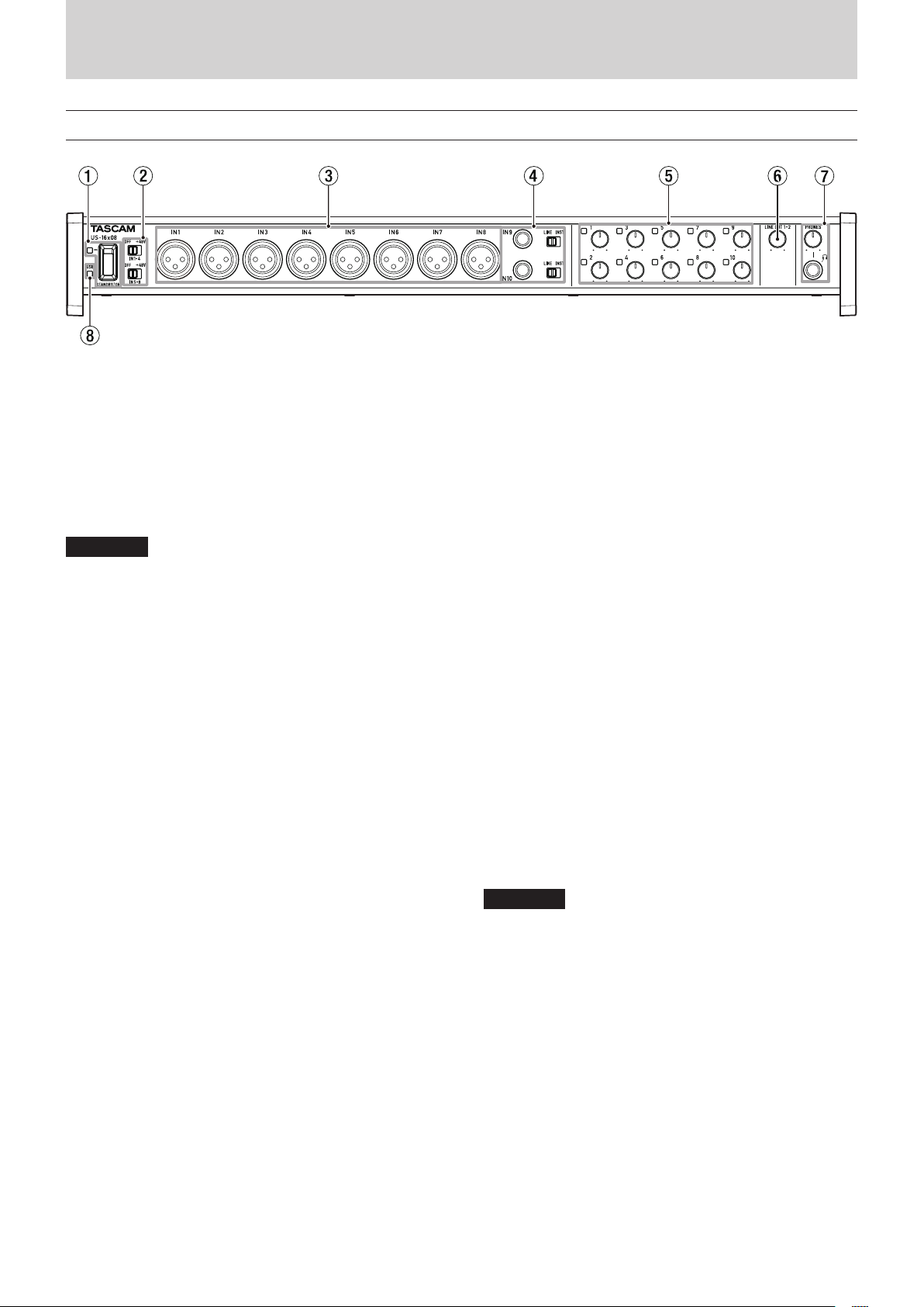
Front panel
1 STANDBY/ON switch and indicator
Press to turn the unit on and to put it into standby. The
STANDBY/ON indicator lights green when the unit is on.
2 Phantom power switches
Use these switches to provide +48V phantom power to the
IN 1–4 and IN 5–8 jacks.
These switches each turn phantom power on/off for 4
channels at a time. Phantom power is supplied when a
switch is set to +48V.
CAUTION
•
Before using these switches to turn phantom power on
(+48V) or OFF, set the PHONES and LINE OUT 1-2 knobs
to their minimum values. Failure to do so could cause a loud
noise that might damage other equipment or harm people.
•
Do not connect or disconnect mics when a switch is set to
+48V.
•
Do not supply phantom power to an unbalanced dynamic
mic.
•
Supplying phantom power to some ribbon mics will break
them. If you are unsure, do not supply phantom power to a
ribbon mic.
3 IN 1-8 (BALANCED) jacks
These are analog XLR input jacks. You can adjust their input
gains with the gain knobs.
(1: GND, 2: HOT, 3: COLD)
4 IN 9-10 (balanced/unbalanced) jacks and LINE/INST
switches
These are standard analog TRS input jacks.
The LINE/INST switches enable support for both line
input, including audio equipment and keyboards, and high
impedance input, including direct input of guitars.
You can adjust their input gains with the gain knobs.
(Tip: HOT, Ring: COLD, Sleeve: GND)
5 Gain knobs and overload indicators
Use the 1–10 gain knobs to adjust the gain of IN 1-10
independently.
These can set the gain for IN 1-8 between −12 dBu and −68
dBu and for IN 9-10 between +4 dBu and −42 dBu (between
−12 dBV and −57 dBV during guitar input).
The overload indicators to the upper left of each of the 1–10
gain knobs light just before an input is about to distort
(when the signal exceeds −1 dBFS).
6 LINE OUT 1-2 knob
Use this knob to adjust the output level of the LINE OUT 1-2
jacks on the back of the unit.
7 PHONES jack and knob
Use this standard stereo jack to connect stereo headphones.
The sound output is the same as the signals output from the
LINE OUT 1-2 jacks.
Use the PHONES knob to adjust the headphone output
level.
TASCAM US-16x08
4
8 USB indicator
This lights orange when the USB connection is working.
CAUTION
Before connecting headphones, minimize the volume with
the PHONES knob. Failure to do so might cause sudden loud
noises, which could harm your hearing or result in other
trouble.
Page 5
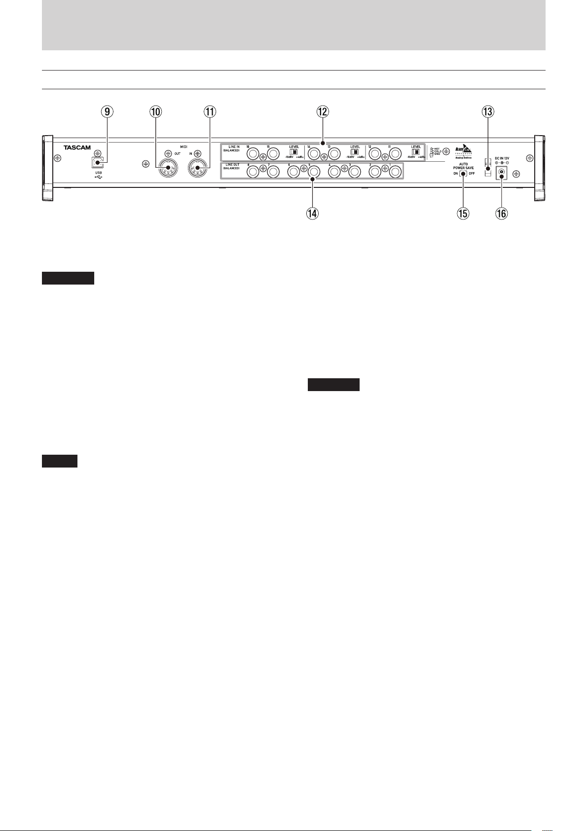
Rear panel
2 – Names and functions of parts
9 USB port
Use the included USB cable to connect the unit to a
computer or iOS device (supports USB 2.0).
CAUTION
•
USB 1.1 is not supported.
•
When connected to a USB 3.0 port, it will function in High
Speed mode equivalent to USB 2.0 (480 Mbps maximum).
0 MIDI OUT connector
This 5-pin DIN is a standard MIDI output connector.
This outputs MIDI signals.
q MIDI IN connector
This 5-pin DIN is a standard MIDI input connector.
Use this to input MIDI signals.
w LINE IN 11-16 (balanced) jacks and switches
These are standard TRS line input jacks. Use the LEVEL
switches to set the nominal level to −10 dBV or +4 dBu.
(Tip: HOT, Ring: COLD, Sleeve: GND)
NOTE
The input gain cannot be adjusted for these jacks.
e Cord holder
Attach the cord of the included AC adapter here to prevent
the plug from becoming disconnected.
r LINE OUT 1-8 (balanced) jacks
These are standard TRS analog line output jacks. Their
nominal output levels are +4 dBu.
(Tip: HOT, Ring: COLD, Sleeve: GND)
t AUTO POWER SAVE switch
This can be set to have the unit turn itself off (start standby)
automatically if no input signal (above −60 dBFS) has been
detected for 30 minutes when operating in mic preamp
mode.
CAUTION
If you want to turn the unit on again after it has turned itself
off (entered standby) automatically using this function, set
the STANDBY/ON switch to STANDBY once, wait at least 8
seconds and then set it to ON again.
y DC IN 12V connector
Connect the included AC adapter (GPE248-120200-Z) here.
TASCAM US-16x08
5
Page 6

3 – Installation
System requirements
Check the TEAC Global Site (http://teac-global.com/) for the
latest information about supported operating systems.
Windows
8
Supported operating systems
Windows 8 (including 8.1) 32-bit
Windows 8 (including 8.1) 64-bit
Windows 7 32-bit SP1 or later
Windows 7 64-bit SP1 or later
8
Computer hardware requirements
Windows computer with a USB 2.0 or USB 3.0 port
8
CPU/processor speed
2 GHz or faster dual core processor (x86)
8
Memory
2 GB or more
8
Display resolution
Display with 1280x800 resolution
CAUTION
Operation of this unit was confirmed using standard
computers that meet the above requirements. This does
not guarantee operation with all computers that meet the
above requirements. Even computers that meet the same
system requirements might have processing capabilities
that differ according to their settings and other operating
conditions
Supported audio drivers
Windows: ASIO2.0, WDM, MIDI
Mac: Core Audio, Core MIDI
Installing the driver and Settings Panel
To use this unit with a Windows computer, a driver and Settings
Panel must be installed on it. To use this unit with a Mac, a driver
does not need to be installed, but the Settings Panel must be
installed in order to use the DSP mixer functions.
Download the latest driver and Settings Panel for the operating
system you are using from the TEAC Global Site (http://
teac-global.com/).
i When you install the driver on a Windows computer, the
Settings Panel will be installed at the same time.
i Only the Settings Panel needs to be installed on a Mac. This
unit can be operated with the standard Mac OS driver, so
there is no need to install a driver.
i When using this unit with an iOS device, the standard OS
driver will be used, so there is no need to install a driver or
Settings Panel.
CAUTION
Restarting the computer might be necessary after installation or uninstallation completes. Save your data and
conduct other necessary steps in other applications before
quitting them.
Installing the driver and Settings Panel for Windows
NOTE
If noise occurs, please set your computer’s power options to
“High Performance”.
Mac OS X
8
Supported operating systems
OS X Yosemite (10.10 or later)
OS X Mavericks (10.9.1 or later)
OS X Mountain Lion (10.8.4 or later)
8
Computer hardware requirements
Apple Mac computer with a USB 2.0 or USB 3.0 port
8
CPU/processor speed
2 GHz or faster dual core processor
8
Memory
2 GB or more
8
Display resolution
Display with at least 1280x800 resolution
iOS devices
Apple devices running iOS 7 or later
NOTE
i Complete installation of the driver on the computer before
connecting the unit to it with the USB cable. If you already
connected the unit using the USB cable before installing the
driver, and the Found New Hardware Wizard launched on the
computer, close the Wizard and disconnect the USB cable.
8
Installation procedures
1. Download the latest driver for the operating system you are
using from the TEAC Global Site (http://teac-global.com/)
and save it on the computer to be used with the unit.
2. Open the saved driver (zip file) on, for example, the
computer desktop.
3. Double-click the “US-16x08_Installer.exe” file in the folder
that appears after uncompression to automatically launch
the installation software.
CAUTION
If you open a zip file without decompressing it and doubleclick the “US-16x08_Installer.exe” file in the folder that
opens, installation will not start. Right-click the zip file and
select “Extract All”, for example, to decompress it and then
try again.
4. When a “Security Warning” or “User Account Control” screens
appear, click the “Yes” button.
TASCAM US-16x08
6
Page 7
3 – Installation
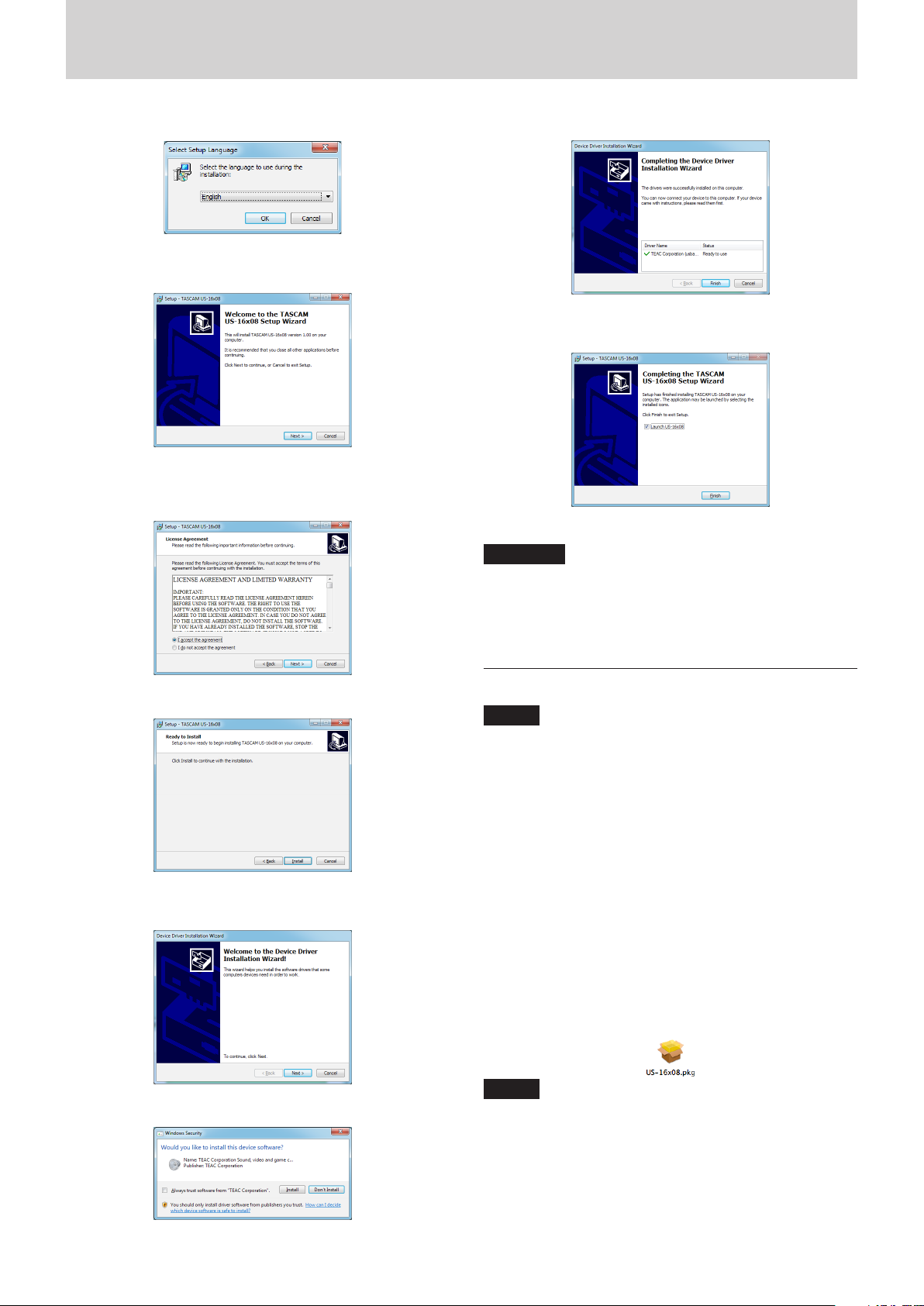
5. Next, select a language and click the “OK” button.
6. When the Setup Wizard screen appears, click the “Next”
button.
7. Read the contents of the License Agreement, and select
“Agree (A)” if you agree to the terms. Then, click the “Next”
button.
11. Click the “Finish” button when the screen below appears.
12. The following screen appears when installation has
completed. Click the “Finish (F)” button.
The installer will quit and the Settings Panel will launch.
CAUTION
•
When installing the driver, a warning might appear with a
message such as, “The software you are installing for the
hardware has not passed Windows Logo testing to verify its
compatibility with Windows.” If this message appears, click
“Continue Anyway” to proceed with the installation.
8. Next, click the “Install (I )” button.
9. When the Install Wizard screen appears, click the “Next (N)”
button.
10. Next, click the “Install (I)” button to start installation.
Installing the Mac OS X Settings Panel
NOTE
•
Install the Settings Panel on the computer before
connecting the unit to it with the USB cable. If the unit is
connected by the USB cable, cancel driver installation and
disconnect it before starting driver installation again.
•
During Settings Panel installation a warning message
like this might appear: “US-16x08.pkg can't be opened
because it was not downloaded from the Mac App Store.”
If a message like this appears, follow the instructions in
“Working with Gatekeeper” on page 8 in this manual
and then proceed with the installation.
8
Installation procedures
1. Download the latest Settings Panel for the operating system
you are using from the TEAC Global Site (http://teac-global.
com/) and save it on the computer to be used with the unit.
2. Double-click “US-16x08_X.XX.dmg”, which is the saved disk
image file for the Settings Panel, and double-click “US-16x08.
pkg” inside the folder that opens.
NOTE
Depending on the computer’s settings, the downloaded zip
file might not have opened automatically. In this case, open
the zip file first and then double-click the disk image file.
TASCAM US-16x08
7
Page 8
3 – Installation
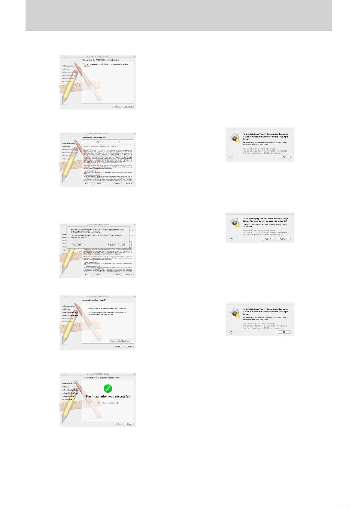
3. When the installer starts, click the “Continue” button.
4. Next, select the desired language and click the “Continue”
button.
5. Click the “Read License” button and check the contents
of the Software License Agreement. If you agree to the
contents of the license, click “Agree”.
Then, click the “Next” button.
8
Working with Gatekeeper
When using Mac OS X, depending on the Gatekeeper security
function setting, a warning message might appear during
installation.
Resolution depends on the warning message shown.
See the following explanations for details.
When the Gatekeeper setting is “Allow applications
downloaded from: the Mac App Store"
The following security warning might be shown: “'US-16x08.
pkg' can't be opened because it was not downloaded from
the Mac App Store."
In this case, click the OK button to close the message. Then,
control-click (or right-click) the file and click “Open”.
Click the “Open” button if the following security warning
message appears: “'US-16x08.pkg' can't be opened because
it was not downloaded from the Mac App Store. Are you
sure you want to open it?"
6. Next, click the “Install” button to start installation.
7. The following screen appears when installation has
completed. Click the “Close” button.
This message might also appear when the Gatekeeper
setting is something other than “Allow applications
downloaded from: the Mac App Store"
The security warning message “'US-16x08.pkg' can't be
opened because it was not downloaded from the Mac App
Store.” could appear again, and you might not be able to
open the file.
In this case, copy the file from the folder where it is to the
desktop or another folder, and then open it. Alternatively,
change the Gatekeeper settings to “Allow applications
downloaded from: the Mac App Store and identified developers” and try opening it again.
The Settings Panel will launch.
TASCAM US-16x08
8
Page 9
3 – Installation
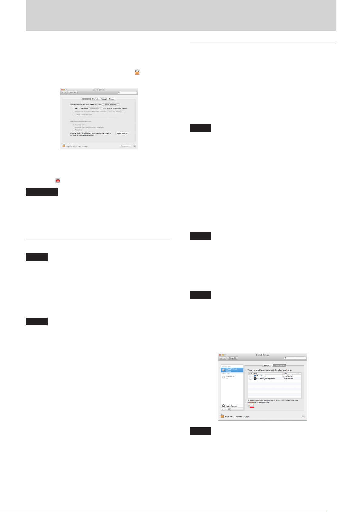
Changing the Gatekeeper setting
The Gatekeeper setting can be changed using the “Allow
applications downloaded from:” item on the “General” page
of the “Security & Privacy” pane of the System Preferences.
To change this, you must click the lock icon ( ) at the
bottom left and enter a password to unlock the settings.
This setting will lock again when you click the “Show All”
button at the top left of the window to close the open pane
or when you quit the System Preferences by, for example,
clicking the round button at the top left corner of the
window ( ) or typing command-Q.
CAUTION
Changing the Gatekeeper settings could result in security
risks.
If you changed the Gatekeeper setting to decrease security
(use one of the lower settings), set it back to the original
setting after updating the driver and/or firmware.
Uninstalling the driver and Settings Panel
NOTE
Normally, there is no need to uninstall the driver or Settings
Panel. Follow these procedures if a problem occurs or you no
longer intend to use the unit with the computer.
8
Windows
Uninstall from the “Programs and Features” Control Panel.
1. From the Start menu, open the Control Panel, and then
Programs and Features.
NOTE
In Windows 8, to open the Control Panel, right-click the
Start screen and click the “All apps” button (or click the
button that appears at the bottom left of the Start screen in
Windows 8.1), then click “Control Panel” on the Apps screen.
2. If “View by:” is set to “Category”, click “Uninstall a program”
under the “Program” item.
If “View by:” is set to “Large icons” or “Small icons”, click
“Programs and Features”.
3. Double-click “TASCAM US-16x08 version X.XX” ("X.XX” is the
driver version) in the list.
4. Then, follow the instructions that appear on the screen.
8
Mac OS X
Delete the “US-16x08” application from the Application folder to
complete uninstallation.
â
¡
Automatic launching of the Settings Panel
The Settings Panel will automatically launch when the computer
starts up.
This allows the Settings Panel to apply its parameter settings,
for example, to the unit. If you use this unit without starting the
Settings Panel, the unit will use the default Settings Panel values
for parameters. (For information about the default values of the
Settings Panel, see “Initializing the Settings Panel settings” on
page 19.)
If you do not want the Settings Panel to launch automatically
when the computer is started, follow these procedures.
NOTE
•
The automatic launching setting for the Settings Panel
applies only to the user account that was logged in when it
was installed.
•
The Settings Panel cannot be used on an iPad or other iOS
device.
Windows OS
Windows 8
1. Right-click the Start screen to show the App Bar. In
Windows 8, right-click the Start screen and click the “All
apps” button (or the
screen in Windows 8.1), and click “Task Manager” to open
it.
2. Right-click “US-16x08” in the “Start-Up” tab and select
“Disable” from the menu.
NOTE
If you want to enable automatic launching of the Settings
Panel again, right-click “US-16x08” and select “Enable”
from the menu.
Windows 7
Click the Start button, select All Programs and then
Startup. Right-click “US-16x08” and select “Delete” from
the menu.
NOTE
If you want to enable automatic launching of the Settings
Panel again, add a shortcut for “US-16x08” to the Startup
menu.
Mac OS X
Open the System Preferences app and open the Users &
Groups pane. Click Login Items, select “US-16x08_SettingsPanel” and click the − button.
NOTE
If you want to enable automatic launching of the Settings
Panel again, click the + button and select “US-16x08_
SettingsPanel”.
â
button at the bottom left of the
¡
TASCAM US-16x08
9
Page 10
$%
3
4 – Preparation
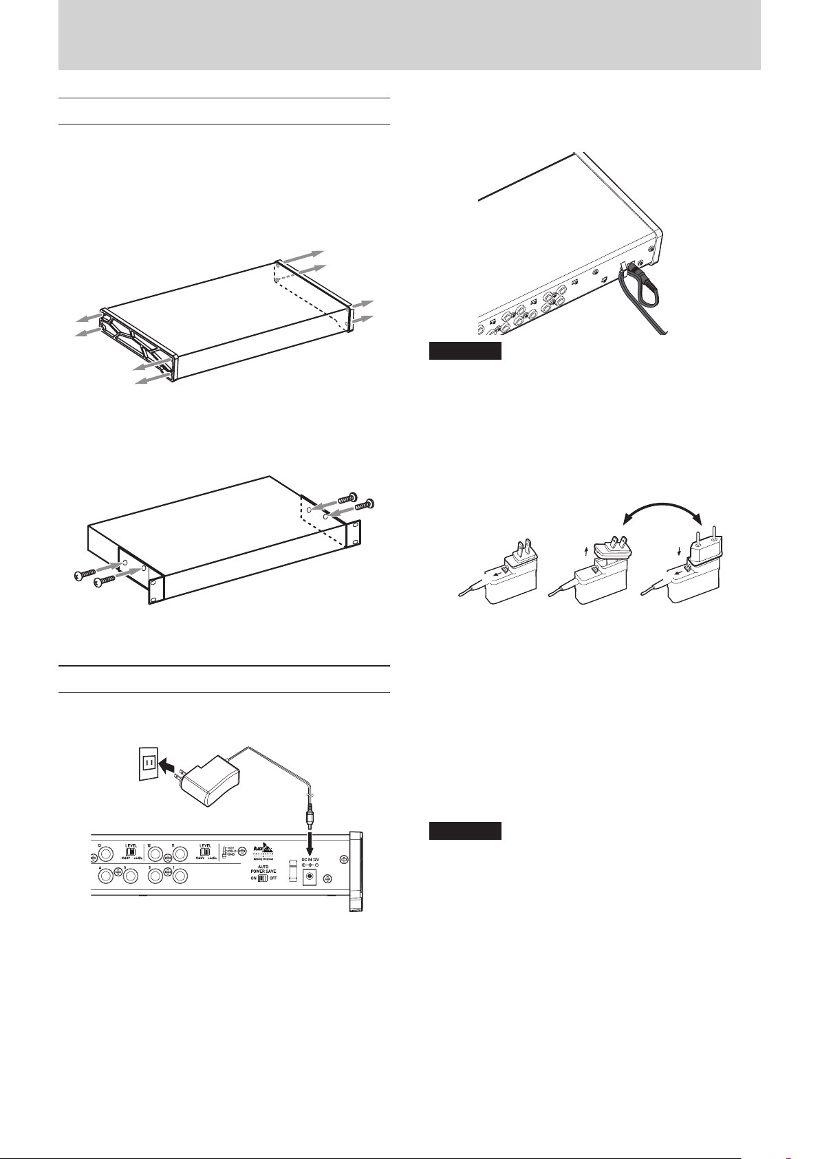
Attaching the rackmount angles
In order to mount this unit in a rack, you must remove the
frames and install the included rackmount angles. Follow these
procedures to change them.
(You will need a flat-bladed screwdriver.)
1. Use the hex key included with this product to remove the
four screws on each side from the positions shown below.
2. Remove the frames from both sides of the unit
3. Attach the included rackmount angles using the rackmount
angle attachment screws and the Phillips screwdriver that
you prepared.
In order to prevent the cord from becoming disconnected
during use, always wrap the cord around the cord holder when
connecting it.
CAUTION
•
Always use the AC adapter (GPE248-120200-Z) that was
shipped with the unit. Using a different AC adapter could
cause malfunction, overheating, fire or other problems.
•
The AC adapter for this unit includes two types of outlet
plugs. Attach the type of plug that matches the power outlet
that you are using.
8
Changing the outlet plug
4. Reverse these procedures to reinstall the frame pieces originally attached to the unit.
Connecting the power
Use the included AC adapter to connect a power supply to the
unit as shown below.
Power outlet
GPE248-120200-Z (included)
DC plug
2
1
1. Move the latch on the AC adapter in the direction of the
arrow.
2. Pull off the outlet plug.
3. Replace it with the other outlet plug (A or B).
4. Move the latch on the AC adapter in the direction of the
arrow again.
5. Attach the outlet plug to the AC adapter.
This completes changing the outlet plug.
After changing the outlet plug, confirm that it is not loose
or crooked and that everything is normal before plugging it
into an outlet.
5
4
CAUTION
Do not use the adapter if there is anything abnormal about
the plug after changing it. Use when the plug is abnormal
could cause fire or electric shock. Contact the retailer where
you purchased the unit or a TEAC service center (on the back
cover) to request repair.
TASCAM US-16x08
10
Page 11
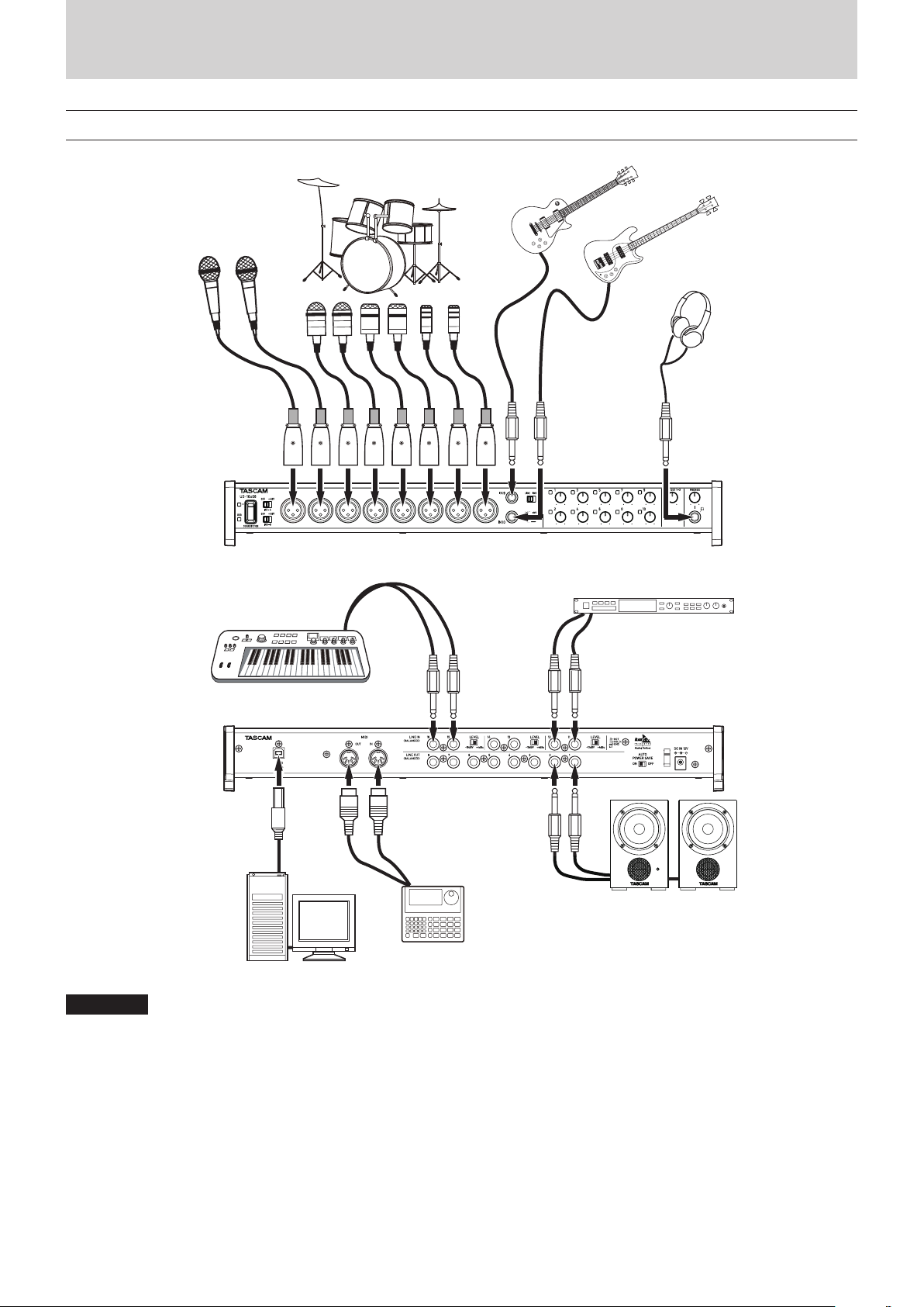
Examples of connections with other equipment
5 – Connections
Vocal mics
Drums
Guitar
Bass Guitar
Headphones
Sound module
Keyboard
USB
Powered speakers or
amplifier and speakers
Drum machine
Computer
CAUTION
•
Before making connections, turn this unit and all equipment to be connected off (standby).
•
The phantom power switches change the settings for groups of 4 channels. Do not set phantom power to +48V when an unbalanced
dynamic mic is connected.
•
Do not connect or disconnect mics while phantom power is set to +48V. Doing so could cause a loud noise and might damage this
unit and connected equipment.
•
Set the LINE OUT and PHONES knobs to their minimum values before switching the phantom power setting between +48V and OFF.
Sudden loud noises from monitoring equipment could occur, and this could damage the equipment or harm hearing.
•
Supplying phantom power to some ribbon mics will break them. If you are unsure, do not supply phantom power to a ribbon mic.
TASCAM US-16x08
11
Page 12

5 – Connections
Computer connections
Use the included USB cable to connect the unit to a computer
USB 2.0/3.0 port. When the USB connection is working, the USB
indicator on the front of the unit lights.
CAUTION
•
If you connect this unit to a computer via a USB hub, for
example, audio signal dropouts, clicking noises and other
interference could occur due to the influence of other USB
devices connected to that hub. For this reason, we strongly
recommend connecting this unit to a separate USB port.
Connecting USB keyboards and mice, however, to the same
bus should not be a problem.
Audio connections
Analog audio signals input into this device from mics, guitars,
keyboards and other audio equipment can be converted into
digital signals and transmitted to the computer via USB. In
addition, by connecting speakers (through an amplifier if not
powered) or headphones to this unit, you can monitor audio
signals that are input to this unit and output from the computer.
CAUTION
Before connecting audio equipment, set the unit’s 1-10
gain, LINE OUT 1-2 and PHONES knobs to their lowest
values. Failure to do so could cause sudden loud noises
from monitoring equipment, and this could damage the
equipment or harm hearing.
Microphones
•
Dynamic mics
Connect mics to the IN 1-10 jacks on the front of the unit.
•
Condenser mics
When using condenser mics that require phantom power,
connect them to the IN 1-8 jacks, and set the phantom
power switches to +48V.
Guitar
When connecting a guitar or bass guitar directly to this unit, use
the IN 9 or IN 10 jack on the front of the unit and set the LINE/
INST switch for that jack to INST.
Electronic and audio devices and other equipment
When connecting an electronic instrument or other audio
equipment directly to this unit, use the IN 9-10 jacks on the
front of the unit or the IN 11-16 jacks on the back and set the
LINE/INST switches for those jacks to LINE.
Analog record players
The output of an analog record player cannot be connected
directly to this unit. To connect an analog record player to this
unit, a phono amp and equalizer (or an audio amplifier that has
phono input jacks) must be connected between them.
Monitor speakers
Connect monitor speakers (powered speakers or an amplifier
and speaker system) to the LINE OUT 1-2 jacks on the back of
the unit.
Use the LINE OUT 1-2 knob on the front of the unit to adjust the
speaker volume.
Headphones
Connect headphones to the PHONES jack (standard stereo) on
the front of the unit.
CAUTION
Before connecting headphones, minimize the volume with
the PHONES knob. Failure to do so might cause sudden loud
noises, which could harm your hearing or result in other
trouble.
CAUTION
•
Before making connections, turn this unit and all equipment
to be connected off (standby).
•
Do not connect or disconnect mics while phantom power is
set to +48V. Doing so could cause a loud noise and might
damage this unit and connected equipment.
•
Set the LINE OUT and PHONES knobs to their minimum
values before switching the phantom power setting
between +48V and OFF. Sudden loud noises from
monitoring equipment could occur, and this could damage
the equipment or harm hearing.
•
Supplying phantom power to some ribbon mics will break
them. If you are unsure, do not supply phantom power to a
ribbon mic.
MIDI connections
Connect sound modules, keyboards, synthesizers, drum
machines and other MIDI devices to the unit in the following
manner.
•
If you want to monitor sound from a MIDI device, connect its
outputs to this unit's IN 9-16 jacks or use an external mixer.
•
You can also use the MIDI IN and MIDI OUT connectors
on the back of the unit to send and receive MIDI timecode
(MTC). By doing this, you can use an application that
supports MTC to synchronize a multitrack recorder (MTR)
and MIDI devices.
CAUTION
When using Windows Media Player, if the “Sound and Audio
Devices Properties” Control Panel “MIDI music playback
(default device)” is set to “Microsoft GS Wavetable SW
Synth”, you will not be able to hear MIDI performances
through this unit's LINE OUT 1-8 or PHONES jacks.
Connecting with iOS devices
A Lightning to USB Adapter is required.
You will need to prepare an Apple genuine Lightning to USB
Adapter (sold separately).
TASCAM US-16x08
12
Page 13

6 – Using the Settings Panel
You can use the Settings Panel to change and save settings for
the various functions of the unit.
Opening the Settings Panel
Launch the Settings Panel installed on the computer to show it
on the computer display.
Open the Settings Panel in the following ways.
NOTE
The Settings Panel cannot be used on an iPad or other iOS
device.
8
Windows OS
•
Select the Settings Panel from “All Programs” or “All apps"
Windows 8
In Windows 8, right-click the Start screen and click the “All
apps” button (in Windows 8.1, the
at the bottom left of the Start screen) to open the Apps
screen. On this screen, click the “US-16x08 Settings Panel”
item under “TASCAM” to open the Settings Panel.
Windows 7
Start button w All Programs w select “US -16x08
Settings Panel” under TASCAM to open the Settings Panel.
•
In Windows 8, select “US-16x08 Settings Panel” on the Start
screen to open the Settings Panel.
â
button that appears
¡
Settings Panel screen
The Settings Panel has three tabbed pages.
Click a tab at the top of the Settings Panel to open that page.
MIXER: Make built-in mixer and effects settings on this page.
INTERFACE: This page shows the current status of the driver
and information about connections. It also allows you to
change various settings (Windows only).
OUTPUT SETTING: Make settings for each output on this
page.
CAUTION
•
When you open the Settings Panel, it will have the same
state as when it was last closed, but the settings data is
not saved automatically. To save the settings of every
page (MIXER, INTERFACE and OUTPUT SETTING), use the
Scene Memory menu in the menu bar. See “Settings Panel
pull-down menus” on page 19 in this manual.
•
The signals input through each of the 16 channels are transmitted to the computer without being affected by SOLO,
MUTE, PAN, and fader settings. For this reason, fader and
pan changes made in the Settings Panel will not alter the
signals sent to a DAW on the same computer.
For details, see “Block diagrams” on page 31.
NOTE
In Windows 8.1, the application is not automatically added
to the Start screen.
•
Open the Settings Panel from the Control Panel.
Windows 8
1. In Windows 8, right-click the Start screen and click
the “All apps” button (or s button that appears at the
bottom left of the Start screen in Windows 8.1), and
click “Control Panel” to open it.
2. If the Control Panel is showing categories, set the “View
by:” item to “Large icons” or “Small icons”.
3. Select “US-16x08 Settings Panel” to open the Settings
Panel.
Windows 7
1. Click the Start button and select “Control Panel” to
open the Control Panel.
2. If the Control Panel is showing categories, set the “View
by:” item to “Large icons” or “Small icons”.
3. Select “US-16x08 Settings Panel” to open the Settings
Panel.
NOTE
In Windows 8, you can also open the Control Panel by
clicking the Control Panel item in the menu that appears if
you right-click the bottom left corner of the desktop.
8
Mac OS X
•
Using the Finder, open the Applications folder and click
“US-16x08_SettingsPanel” to open the Settings Panel.
•
In the Audio Devices window of the Audio MIDI Setup
application, right-click (control-click) “US-16x08” (or click
the settings icon when the unit name is selected) and click
“Configure device…” to open the Settings Panel.
TASCAM US-16x08
13
Page 14

6 – Using the Settings Panel
4
6
8
w
2
MIXER page
1
3
5
7
9
0
q
Windows Settings Panel screen
NOTE
On a Mac, “View” and “SceneMemory” appear in the menu
bar at the top of the screen. For details, see “Settings Panel
pull-down menus” on page 19.
1 EQUALIZER (4-band parametric EQ)
Use the equalizer to increase or decrease the levels of
specific frequency ranges. This can be used, for example,
to enhance the sound of individual instruments, to adjust
the balance of a wide frequency range and to cut specific
unwanted frequencies.
The frequency response with the current settings is shown
as a graph even when the equalizer is off.
The equalizer has a high-shelf HIGH band, a low-shelf LOW
band and peaking (bell-shaped) HIGH MID and LOW MID
bands.
HIGH GAIN knob
Sets the amount the level is increased or decreased for
the HIGH band.
Range: ±12 dB (default: 0 dB)
HIGH FREQ knob
Sets the cutoff frequency of the HIGH band.
Range: 1.7 kHz – 18.0 kHz (default: 5.0 kHz)
HIGH MID GAIN knob
Sets the amount the level is increased or decreased for
the HIGH MID band.
Range: ±12 dB (default: 0 dB)
HIGH MID FREQ knob
Sets the center frequency of the HIGH MID band.
Range: 32 Hz – 18.0 kHz (default: 1.2 kHz)
HIGH MID Q knob
Sets the acuteness of the peak of the HIGH MID band.
The higher the value the more acute it becomes, making
it affect a narrower frequency band. The lower the value,
the less acute it becomes, making it affect a broader
frequency band.
Range: 0.25 – 16.00 (default: 1.00)
LOW MID GAIN knob
Sets the amount the level is increased or decreased for
the LOW MID band.
Range: ±12 dB (default: 0 dB)
LOW MID FREQ knob
Sets the center frequency of the LOW MID band.
Range: 32 Hz – 18.0 kHz (default: 300 Hz)
LOW MID Q knob
Sets the acuteness of the peak of the LOW MID band.
The higher the value the more acute it becomes, making
it affect a narrower frequency band. The lower the value,
the less acute it becomes, making it affect a broader
frequency band.
Range: 0.25 – 16.00 (default: 1.00)
LOW GAIN knob
Sets the amount the level is increased or decreased for
the LOW band.
Range: ±12 dB (default: 0 dB)
LOW FREQ knob
Sets the cutoff frequency of the LOW band.
Range: 32 Hz – 1.6 kHz (default: 80 Hz)
LCF button
Turn the LCF button on to enable the low-cut filter, which
cuts noise and other sounds at low frequencies.
Off (default): LCF button unlit
On: LCF button lit
To set the equalizer for a channel, select its Analog X button
(3).
The equalizer settings will be shown for the channel selected
by its Analog X button (3).
TASCAM US-16x08
14
Page 15

6 – Using the Settings Panel
2 COMPRESSOR
When the input volume exceeds the THRESHOLD level,
the input volume is compressed, reducing output volume
variation.
For example, by reducing the high level parts of sounds
as they occur, a more even volume level throughout can
be achieved. This allows lower-level sounds to be raised,
resulting in a fuller sound.
Three meters show the level of the signal input to the
compressor (INPUT), the level of the signal output from the
compressor (OUTPUT) and the gain reduction caused by the
compressor (GR).
THRESHOLD knob
Sets the threshold level that will cause the effect to start.
Range: −32 dB – 0 dB (default: 0 dB)
RATIO knob
Sets the compression ratio for the input volume.
Turning it right raises the compression ratio, increasing
the amount of compression.
Range: 1.0:1 – inf:1 (default: 1.0:1)
GAIN knob
Sets the gain of the output signal.
When the volume is compressed, the output level
becomes lower than the input level. Use the GAIN knob
to increase the output level so that it is close to the input
level.
Range: 0 dB – 20 dB (default: 0 dB)
ATTACK knob
Sets the amount of time until the compression reaches
the compression RATIO setting after the input volume
exceeds the threshold.
Range: 2 ms – 200 ms (default: 2 ms)
RELEASE knob
Sets the amount of time until the compression stops and
the sound returns to its uncompressed level after the
input sound goes below the threshold.
Range: 10 ms – 1000 ms (default: 10 ms)
To set the compressor for a channel, select its Analog X
button (3).
The compressor settings will be shown for the channel
selected by its Analog X button (3).
NOTE
•
If the input is a stereo signal (stereo-linked channel or
master), compression will start and be applied to both
channels when either the left or right input channel exceeds
the threshold level.
•
When the compressor is off, the compressor curve will
appear but the meters will not be active.
3 Analog X buttons
When an Analog X button ("X” is the channel number) is on
(lit), the equalizer (1) and compressor (2) settings for that
channel will be shown and can be adjusted as desired.
Off (default): Analog X button unlit
On: Analog X button lit
You can only select one channel at a time. Multiple Analog X
buttons cannot be on at the same time.
When a channel is selected, click a different channel's button
to select that channel. The previously selected channel
button will become unlit, and the newly selected channel
button will light.
4 PHASE buttons
Turn a PHASE button on to reverse the phase of that
channel.
5 EQ buttons
Turn an EQ button on to enable the equalizer on that
channel.
6 COMP buttons
Turn a COMP button on to enable the compressor on that
channel.
7 SOLO buttons
Turn a SOLO button on to solo that channel.
With this unit, when the SOLO button of a channel is
enabled, all other channels are automatically muted (solo-inplace monitoring).
The MUTE buttons for channels that are muted will light.
(Default: off)
Multiple channels can be soloed at the same time.
NOTE
•
When all the SOLO buttons are off, clicking the SOLO
button of one channel will put the unit into solo mode and
automatically mute the other channels, lighting their MUTE
buttons.
•
When all SOLO buttons are disabled, channels that had
been automatically muted will become unmuted. Channels
that had been individually muted before the unit entered
solo mode will remain muted.
•
The MASTER L/R channel MUTE button will not turn on
automatically when the unit enters solo mode.
8 MUTE buttons
Turn a MUTE button on to mute that channel.
(Default: off)
NOTE
In addition to turning the MUTE button on and off, channels
will be automatically muted and unmuted when SOLO
buttons are used
9 Pan sliders
Use these to adjust the stereo positions of the signals input
to each channel when they are sent to the stereo bus.
Use the mouse to click and drag a pan slider left or right to
adjust the position.
While dragging the mouse, the value being adjusted is
shown in its fader level display area (above 0).
The value is L20 when set all the way to the left, C when set
in the center and R20 when set all the way to the right.
Setting range: L20 – L1, C (default), R1 – R20 (41 steps
total with C at the center and 20 steps to both left and
right.)
A pan slider appears blue when centered (C) and yellow at
all other positions.
NOTE
•
If a pan slider is centered (C), the signal is reduced by 3 dB
and sent to both the left and right channels of the stereo
bus.
•
Double-click a pan slider to return it to the center (C)
position.
•
When a pan slider is set to the left end (L20), the signal for
that channel is sent only to the left channel of the stereo
bus. It is not sent to the right channel of the stereo bus.
TASCAM US-16x08
15
Page 16

6 – Using the Settings Panel
•
When a pan slider is set to the right end (R20), the signal for
that channel is sent only to the right channel of the stereo
bus. It is not sent to the left channel of the stereo bus.
0 Faders and level meters
Use the faders for each channel to adjust the levels of the
channel signal sent to the stereo bus. Use the master fader
to adjust the master output level.
The channel level meters show their signal levels. The master
level meters show the levels of the mixed signal.
The fader level display area (bottom of 0) shows the fader
gain value.
The channel and master level meters show green bars for
values less than −12 dB, yellow bars for −12 dB to −6 dB, and
red bars for values greater than −6 dB.
Each level meter has an overload indicator at its top.
Range: +6 dB to −∞ (default: 0 dB)
NOTE
•
Using the mouse, drag a fader to adjust its level. Move the
fader up to increase the level or down to decrease it.
•
Double-click a fader to return it to its default (0 dB) position.
•
The channel meters show the levels before being adjusted
by the faders. Level meters are not affected by fader adjustments or even their channels being muted.
q LINK buttons
Turn a LINK button on to combine two adjacent channels
(odd and even) into a single stereo channel.
When stereo link mode is enabled, the buttons, knobs and
faders of the two channels are combined. The channel level
meters are also shown as a stereo pair.
When linked, the LINK button lights. (Default: off)
•
Turn a LINK button off to split a single stereo channel into
two mono channels. The settings for each of the mono
channels become as follows.
Analog X-Y: If on when the LINK button is turned off, the
odd channel stays on, but the even channel turns off. If
off when the LINK button is turned off, both channels
stay off.
PHASE: The settings are not changed. The setting of each
channel stays as it was.
EQ: The settings of both channels stay the same as the
combined stereo channel.
COMP: The settings of both channels stay the same as the
combined stereo channel.
SOLO: If on when the LINK button is turned off, this stays
on for both channels. If off when the LINK button is
turned off, both channels stay off.
MUTE: If on when the LINK button is turned off, this stays
on for both channels. If off when the LINK button is
turned off, both channels stay off.
Pan sliders: These stay the same when the LINK button is
turned off.
Level faders: The settings of both channels stay the same
as the combined stereo channel.
w Track notes
You can input up to six English letters and numbers.
How to input characters
Click a note area to ready it for input. The cursor will blink.
Then, use the computer keyboard to input characters.
After you complete inputting characters, press the Enter key
on the computer keyboard.
When a LINK button is enabled (combining two adjacent
channels as a stereo channel), the settings become as
follows.
Analog X: If either the odd or even channel is turned on,
this turns on. If both the odd and even channels are off,
this turns off. In addition, the button name changes to
“Analog X-Y” (“X” is the odd channel number and “Y” is the
even channel number).
PHASE: The settings are not combined. The settings of the
channels do not change.
EQ: The setting of the odd-numbered channel is applied.
COMP: The setting of the odd-numbered channel is
applied.
SOLO: The setting of the odd-numbered channel is
applied.
MUTE: The setting of the odd-numbered channel is
applied.
Pan sliders: The settings are not combined. The setting of
each channel can be set independently.
Level faders: The setting of the odd-numbered channel is
applied.
NOTE
You must press the Enter key on the computer keyboard
after you complete inputting characters to confirm the
input. If you move to a different page from the MIXER page
without pressing the Enter key, the input characters will be
shown, but not saved.
TASCAM US-16x08
16
Page 17

INTERFACE page
1
8
Windows
6 – Using the Settings Panel
8
Mac OS X
1
2
Windows Settings Panel screen
Mac Settings Panel screen
The “INTERFACE” page has a unit status area and, on Windows
only, a “Buffer Size” area.
Beneath these areas is an image of the rear panel of the unit that
you can use to check the layout of the jacks, for example. No
settings can be changed on this page.
1 Status display area
This shows the current status of the unit.
Item displayed Meaning
Software Version
Firmware Version
Device This is the name of the unit.
Sample Rate
1 “No Device” is shown when no device is connected.
2 “No ASIO Driver” is shown when an ASIO driver has not been
installed.
This is the software version used
by unit.
This is the firmware version used
by the unit.
This is the current sampling
frequency.
1
1
2
2 Buffer Size (Windows only)
The driver for the unit stores the audio input and output
signals transferred to and from the computer temporarily in
a buffer. This buffer size can be adjusted.
Smaller buffer sizes result in less audio signal delay (latency),
but require high-speed processing by the computer.
If the processing cannot keep up, for example, due to other
system operations, clicking and popping noises might occur
and the audio signal might even drop out.
Increasing the buffer size will stabilize operation and
suppress negative effects on audio signals, but the delay in
audio signals sent to the computer will increase.
You can use the slider on the panel to adjust the buffer size,
according to the use conditions.
Use the slider to select fixed values that increase from left to
right (64, 128, 256, 512, 1024 and 2048 samples).
TASCAM US-16x08
17
Page 18

6 – Using the Settings Panel
OUTPUT SETTING page
On the OUTPUT SETTING page, you can visually check the routing of signals output from the LINE OUT 1-8 jacks and select them.
1
WindowsPC画面
2
Windows Settings Panel screen
1 Output signal selection
Click a box to the right of a LINE OUT X (“X” is 1–8) label to
open a pull-down menu with BUS line selection options.
Select the signal that you want to output from this menu.
Options: COMPUTER 1 – COMPUTER 8, MASTER L/
MASTER R
2 Output signal routing status
This shows the connection of the signals with the output
jacks as selected in area 1.
•
Stereo BUS outputs
The signals input through each input jack and by USB
output from the computer are mixed and output in stereo.
For details, see “Block diagrams” on page 31 in this
manual.
•
Computer BUS outputs
Select output signals from the Computer BUS (1–8), which
come from DAW software running on the computer, to
output them directly from the desired jacks.
NOTE
The output signals selected for LINE OUT 1 and LINE OUT 2
will also be output from the PHONES (L/R) jack.
TASCAM US-16x08
18
Page 19

Settings Panel pull-down menus
The Settings Panel has View and SceneMemory pull-down
menus that can be used to initialize and save settings, for
example.
View menu
This menu includes functions to restore the settings of the
Settings Panel to their defaults (Initialize), minimize the
application to the taskbar (Minimize) and close the Settings
Panel (Close).
Windows version
6 – Using the Settings Panel
Mac version
2. A confirmation message will appear. Click the “OK” button in
the message window to reset the Settings Panel settings to
their default values.
Windows version
Mac version
Initialize
Select this to reset all the Settings Panel settings.
For details, see “Initializing the Settings Panel settings” on
page 19 in this manual.
Minimize
Minimize the Settings Panel screen to the taskbar (or
Dock on a Mac).
Close
Close the Settings Panel screen and quit the application.
8
Initializing the Settings Panel settings
Select this to reset all the Settings Panel settings.
NOTE
The Windows Buffer Size setting is not restored to the
factory default.
CAUTION
After initializing, you cannot restore the previous settings.
1. In the menu bar, Click “Initialize” in the View menu
(Windows/Mac).
Windows version
Mac version
NOTE
Click the “Cancel” button to return to the Settings Panel
without initializing.
Using the Initialize function will result in the following
settings.
Page Item Default value
MIXER EQUALIZER HIGH (GAIN) 0 dB
HIGH (FREQ) 5.0 kHz
HIGH MID (GAIN) 0 dB
HIGH MID (FREQ) 1.2 kHz
HIGH MID (Q) 1.00
LOW MID (GAIN) 0 dB
LOW MID (FREQ) 300 Hz
LOW MID (Q) 1.00
LOW (GAIN) 0 dB
LOW (FREQ) 80 Hz
LCF OFF
COMPRESSOR THRESHOLD 0 dB
RATIO 1.0: 1
GAIN 0 dB
ATTAC K 2 ms
RELEASE 10 ms
PAN C (center)
Channel faders 0 dB
Master fader 0 dB
OUTPUT
SETTING
LINE OUT 1 COMPUTER 1
LINE OUT 2 COMPUTER 2
LINE OUT 3 COMPUTER 3
LINE OUT 4 COMPUTER 4
LINE OUT 5 COMPUTER 5
LINE OUT 6 COMPUTER 6
LINE OUT 7 COMPUTER 7
LINE OUT 8 COMPUTER 8
NOTE
•
If you turn the unit on without launching the Settings Panel,
the LINE OUT 1-8 output settings will be set to COMPUTER
1–8.
•
There is no Settings Panel for iOS devices, so the unit will
operate with its default settings.
TASCAM US-16x08
19
Page 20

6 – Using the Settings Panel
SceneMemory menu
Up to 10 Settings Panel states can be saved as scene
memories.
The SceneMemory menu starts with 10 SceneMemoryX ("X”
being 1–10) memories. Select one of these scene memories
to open a submenu that allows you to Save, Load or Rename
it.
You can also initialize all 10 scene memories at the same
time.
Windows version
2. Click “Save” in the submenu to save the current Settings
Panel settings to the selected scene memory.
Windows version
Mac version
8
Loading Settings Panel settings
You can immediately change the current Settings Panel
settings to settings saved in a scene memory by loading it.
Mac version
Save
Use this to save all Settings Panel settings except the on/
off status of the Analog X buttons. For details, see “Saving
Settings Panel settings” on page 20 in this manual.
Load
Use this to immediately apply settings that have been
saved to the selected scene memory. For details, see
“Loading Settings Panel settings” on page 20 in this
manual.
Rename
Use this to change the name of the scene memory that is
saved. For details, see “Input and output channels in mic
preamp mode” on page 22 in this manual.
8
Saving Settings Panel settings
The current Settings Panel settings can be saved in a scene
memory.
Ten scene memories can be saved.
CAUTION
Only one set of Settings Panel settings can be saved in each
scene memory. For this reason, saving settings to a scene
memory will erase the previously saved settings.
1. In the menu bar, click the name of a scene memory in the
SceneMemory menu (Windows/Mac) to open the submenu.
CAUTION
If you load a scene memory, the previous settings cannot be
restored. If you want to keep the current settings, save them
to a different scene memory.
1. Click the name of the scene memory that you want to load
in the SceneMemory menu to open the submenu.
2. Click “Load” in the submenu to immediately change the
Settings Panel settings to those saved in the scene memory.
Windows version
TASCAM US-16x08
20
Mac version
Page 21

6 – Using the Settings Panel
CAUTION
Scene memories that you have never saved do not contain
any Settings Panel settings. If you try to load such a scene
memory, the following confirmation message will appear.
Windows version
Mac version
8
Changing a scene memory name
You can change the names of scene memories.
1. From the menu bar, click the name of a scene memory in the
SceneMemory menu (Windows/Mac) to open the submenu.
2. Click “Rename” in the submenu.
8
Initializing all ten scene memories
You can initialize all scene memories at the same time.
CAUTION
After resetting, you cannot restore the previous settings.
1. In the menu bar, click “Initialize Memory” in the SceneMemory menu (Windows/Mac).
Windows version
Windows version
Mac version
3. The following name input window will open.
Windows version
Mac version
2. A confirmation message will appear. Click the “OK” button
in the message window to reset the scene memory Settings
Panel settings to their default values.
Windows version
Mac version
NOTE
Click the “Cancel” button to return to the Settings Panel
without initializing.
Mac version
4. After you complete inputting the new name, click the “OK”
button in the window.
TASCAM US-16x08
21
Page 22

7 – Mic Preamp Mode
Using the unit as a standalone mic preamp
This unit will operate in mic preamp mode when it is not
connected to a computer by USB.
You can use this unit's mic preamps even when it is not
connected to a computer.
8
Input and output channels in mic preamp mode
In mic preamp mode, the routing of input to output channels is
fixed as follows.
Input Output
IN1 LINE OUT1
IN2 LINE OUT2
IN3 LINE OUT3
IN4 LINE OUT4
IN5 LINE OUT5
IN6 LINE OUT6
IN7 LINE OUT7
IN8 LINE OUT8
You can adjust the input level of each channel using its gain
knob.
NOTE
When shipped from the factory, the LINE OUT 1-2 knob is
set to its minimum value, so no sound will be output from
the LINE OUT 1-2 jacks. When using the unit in mic preamp
mode, set the LINE OUT 1-2 knob to its maximum value.
TASCAM US-16x08
22
Page 23

8 – Application Guide
In this chapter, we explain how to set some audio applications
for use with this unit.
8
DAW software
The ways that settings are made differ among DAWs.
When using a DAW software, consult its operation manual.
Windows Media Player
Windows 8
1. Quit all applications and right-click the Start screen to show
the App Bar. Then, click the All apps button to open the
Apps screen.
NOTE
In Windows 8.1, click the
bottom left of the Start screen.
2. Click Control Panel.
3. Click “Hardware and Sound”, and then open the “Sound”
window.
4. On the Playback page, right-click “Line US-16x08”, and click
“Set as Default Device” in the pop-up menu that appears.
When you do this, the green check mark (4) appears next
to Line US-16x08.
â
button that appears at the
¡
Windows 7
1. Quit all applications and open the Control Panel from the
Start button menu.
2. Open “Sound”.
NOTE
If you do not see this item, click Hardware and Sound.
3. On the Playback page, right-click “Line US-16x08”, and click
“Set as Default Device” in the pop-up menu that appears.
When you do this, the green check mark (4) appears next
to Line US-16x08.
NOTE
To use this unit as the recording device, open the Recording
page and use Set as Default Device for Microphone
US-16x08.
5. After completing the setting, click the “OK” button.
6. Launch Windows Media Player, select an audio file and start
playback.
NOTE
•
If you change the setting while Windows Media Player is
running, the software will not recognize that the device has
been changed. In this case, restart Windows Media Player.
•
If you still cannot hear sound after making the settings and
completing the procedures above, restart the computer.
•
If you make this setting, sound will be output through
this unit, but no sound will be output from the computer’s
speakers or headphone jack.
NOTE
To use this unit as the recording device, open the Recording
page and use Set as Default Device for Microphone
US-16x08.
4. After completing the setting, click the OK button.
5. Start Windows Media Player, select an audio file and begin
playback.
NOTE
•
If you change the setting while Windows Media Player is
running, the software will not recognize that the device has
been changed. In this case, restart Windows Media Player.
•
If you still cannot hear sound after making the settings and
completing the procedures above, restart the computer.
•
If you make this setting, sound will be output through this
unit, but no sound will be output by the computer’s speakers
or headphone jack.
TASCAM US-16x08
23
Page 24

8 – Application Guide
Mac OS X and iTunes
1. Open the Utilities folder within the “Applications folder”,
and double-click “Audio MIDI Setup”. Then open the “Audio
Devices” window.
2. Click “US-16x08” to select it and right-click or control-click it.
Then, click “Use this device for sound output” in the pop-up
menu.
The speaker mark appears next to US-16x08.
NOTE
To use this device as the recording device, select “Use this
device for sound input” for the “US-16x08”.
3. Launch iTunes, select an audio file and start playback.
iOS
No settings are necessary to use this unit with an iOS device.
You can use it right away after connecting to the device by
USB.
NOTE
Connecting headphones, for example, to the headphone
jack of the iOS device will interrupt USB communication
with this unit.
TASCAM US-16x08
24
Page 25

9 – MIDI Implementation Chart
8
MIDI Implementation Chart
Function Transmit Recognize Remarks
Basic channels
Mode
Note number Range × × Thru
Velocity
Aftertouch
Pitch bend × × Thru
Control change × × Thru
Program change
System exclusive × × Thru
System common
System real-time
Other
Notes
When power on × ×
Settable × ×
When power on × ×
Messages × ×
Altered ....................
Note on × ×
Note off × ×
Polyphonic × ×
Channel × ×
× ×
Settable range # ....................
Position × ×
Tune × ×
Clock × ×
Command × ×
Local on/off × ×
All notes off × ×
Active sense × ×
Reset × ×
Thru
Thru
Thru
Thru
Thru
ThruSong select × ×
Thru
Thru
Mode 1: OMNI ON, POLY Mode 2: OMNI ON, MONO ˜: YES
Mode 3: OMNI OFF, POLY Mode 4: OMNI OFF, MONO ×: NO
TASCAM US-16x08
25
Page 26

10 – Troubleshooting
Troubleshooting
Please read this chapter if you are unable to use the unit
properly even after setting it up following the procedures in this
manual.
If you are still unable to resolve a problem, please contact a
TASCAM customer center (see back of document) with the
following information about the operating environment and
details about the trouble.
Operating environment
•
Computer manufacturer:
•
Model:
•
CPU:
•
Memory (RAM):
•
Operating system:
•
Applications used:
•
Antivirus software:
•
Wireless LAN use:
See the end of this document for contact information.
8
Installation fails.
8
Installation completes, but the computer does not
recognize the unit.
If some trouble is causing installation to fail, or if the computer
does not recognize the unit even though installation completes,
check the following.
1. Change the USB port
Since the unit might not properly function with some
USB ports, try connecting to a different USB port that is
built into the computer, and reinstall the driver.
NOTE
•
Try again after disconnecting other USB devices. (Keyboards
and mice can be left connected.)
•
Do not use a USB hub. Always connect the unit directly to a
USB port on the computer (built-in).
2. Stop software that is running in the background
Since antivirus software and other software running in
the background can interfere with installation, stop them
before beginning installation. See “Installing the driver
and Settings Panel” on page 6 in this manual for how
to install and uninstall the driver and Settings Panel.
8
There is no sound even when audio is playing back.
The audio output must be set on the computer.
Please confirm the following while the unit is connected to the
computer. Moreover, if you make the following settings, sound
will be output through this unit, but no sound will be output by
the computer’s speakers or headphone jack.
Windows 8/Windows 7
i See the “Windows 8” or “Windows 7” instructions in the
“Windows Media Player” section of the “Application guide”
chapter of the Reference Manual, and make settings as
necessary for the OS.
i Conduct procedures 1-4 for Windows 8 or procedures 1-3 for
Windows 7 to set the default device for playback.
Mac OS X
Quit all applications and open “System Preferences…” from
the Apple menu.
Open “Sound”, and select “US-16x08” on the Output tab.
After completing the setting, restart the computer and
check the sound of playback.
Depending on the application that you are using, you might
need to make additional device settings.
In particular, DAW applications operate using audio engines
with settings that are different from the OS settings, so first
confirm the DAW settings after installing the driver and
Settings Panel for this unit.
Please see the manuals for the applications that you are
using for detailed setting procedures.
8
Sound breaks up or there is noise.
The processing load on the computer causes sound to break up
and noise to occur.
Here are some methods to reduce the load on the computer.
1. A wireless LAN and software running in the background,
including antivirus software, regularly put processing
loads on the computer, which can cause sound to break up
and other noise. Stop wireless LAN transmission, antivirus
software and other software running in the background
when using this unit.
2. Set the buffer size (latency) in the audio application that you
are using or in this unit's Settings Panel to a larger value.
(Windows only)
NOTE
Consult the maker of the audio application that you are
using for methods to reduce its load on your computer.
3. Change the settings of your computer so that they are
optimal for audio processing.
Windows 8
1 In Windows 8, right-click the ordinary Start screen
(Metro user interface screen) and then click “All apps”.
2 Right-click “Computer” and select “Properties”.
3 Click “Advanced system settings”.
4 Click “Settings” in the “Performance” section of the
“Advanced” tab of the “System Properties” window.
5 In the “Visual Effects” tab of the “Performance Options”
window, select “Adjust for best performance”.
Windows 7
a) Turn Aero off.
1 Right-click the desktop and select “Personalize”.
2 Select a “Basic” or “High Contrast” theme.
b) Performance settings
1 Right-click “Computer” and select “Properties”.
2 Click “Advanced system settings”.
3 Click “Settings” in the “Performance” section of the
“Advanced” tab of the “System Properties” window.
4 In the “Visual Effects” tab of the “Performance Options”
window, select “Adjust for best performance”.
Mac OS X
1 Open “System Preferences…” from the Apple menu,
and select “Energy Saver”.
2 Set “Computer sleep” to “Never”.
3 Set “Display sleep” to “Never”.
NOTE
Depending on the Mac OS X version and Mac computer
model, this setting might not be available.
4. Change the USB port
Since the unit might not properly function with some
USB ports, try connecting to a different USB port that is
built into the computer.
TASCAM US-16x08
26
Page 27

NOTE
•
Try again after disconnecting other USB devices. (Keyboards
and mice can be left connected.)
•
Do not use a USB hub. Always connect the unit directly to a
USB port on the computer (built-in).
10 – Troubleshooting
TASCAM US-16x08
27
Page 28

11 – Specifications
Specifications
Ratings
8
Sampling frequencies
44.1/48/88.2/96 kHz
8
Quantization bit depth
16-bit or 24-bit
Analog inputs
8
IN 1-8 mic inputs (balanced)
Connector: XLR-3-31 equivalent
(1: GND, 2: HOT, 3: COLD)
Input impedance: 2.4 kΩ
Nominal input level: −68 dBu (0.0003 Vrms)
(gain knob at maximum)
Nominal input level: −12 dBu (0.195 Vrms)
(gain knob at minimum)
Maximum input level: +8 dBu (1.947 Vrms)
Gain range: 56 dB
8
IN 9-10 instrument inputs (unbalanced)
(LINE/INST switch set to INST)
Connectors: 6.3mm (1/4") standard TS jacks
(Tip: HOT, Sleeve: GND)
Input impedance: 1 MΩ or more
Nominal input level: −57 dBV (0.0014 Vrms)
(gain knob at maximum)
Nominal input level: −12 dBV (0.251 Vrms)
(gain knob at minimum)
Maximum input level: +8 dBV (2.512 Vrms)
Gain range: 45 dB
8
IN 9-10 line inputs (balanced)
(LINE/INST switch set to LINE)
Connectors: 6.3mm (1/4") standard TRS jacks
(Tip: HOT, Ring: COLD, Sleeve: GND)
Input impedance: 10 kΩ
Nominal input level: −41 dBu (0.0069 Vrms)
(gain knob at maximum)
Nominal input level: +4 dBu (1.228 Vrms)
(gain knob at minimum)
Maximum input level: +24 dBu (12.282 Vrms)
Gain range: 45 dB
8
LINE IN 11-16 line inputs (unbalanced)
(LEVEL switch set to “−10dBV")
Connectors: 6.3mm (1/4") standard TS jacks
(Tip: HOT, Sleeve: GND)
Input impedance: 10 kΩ
Nominal input level: −10 dBV (0.3162 Vrms)
Maximum input level: +10 dBV (3.162 Vrms)
8
LINE IN 11-16 line inputs (balanced)
(LEVEL switch set to “+4dBu")
Connectors: 6.3mm (1/4") standard TRS jacks
(Tip: HOT, Ring: COLD, Sleeve: GND)
Input impedance: 10 kΩ
Nominal input level: +4 dBu (1.228 Vrms)
Maximum input level: +24 dBu (12.282 Vrms)
Analog outputs
8
LINE OUT 1-8 line outputs (balanced)
Connectors: 6.3mm (1/4") standard TRS jacks
(Tip: HOT, Ring: COLD, Sleeve: GND)
Output impedance: 100 Ω
Nominal output level: +4 dBu (1.228 Vrms)
Maximum output level: +24 dBu (12.277 Vrms)
8
PHONES output
Connector: 6.3mm (1/4") standard stereo jack
Maximum output: 70 mW + 70 mW
(THD+N 1% or less, into 32 Ω load)
8
Frequency response
8
Input w PHONES output
At 44.1 kHz and 48 kHz
20 Hz – 20 kHz: ±1.0 dB (JEITA), supports Hi-Res
At 88.2kHz and 96kHz
20 Hz – 40 kHz: ±2.0 dB (JEITA), supports Hi-Res
Control input/output ratings
8
MIDI IN connector
Connector: 5-pin DIN
Format: standard MIDI
8
MIDI OUT connector
Connector: 5-pin DIN
Format: standard MIDI
8
USB
Connector: 4-pin USB B-type
Transfer rate: USB 2.0 High Speed (480 Mbps)
TASCAM US-16x08
28
Page 29

11 – Specifications
Audio performance
8
Mic amp EIN (equivalent input noise)
−125 dBu or more
8
Frequency response
8
Input w LINE OUT (BALANCED)
At 44.1 kHz and 48 kHz
20 Hz – 20 kHz: ±0.5 dB (JEITA)
At 88.2kHz and 96kHz
20 Hz – 40 kHz: ±0.5 dB (JEITA)
8
S/N ratio
100 dB or higher
(LINE IN w LINE OUT, gain knob at minimum, JEITA)
8
Distortion
0.006% or less
(Mic/LINE IN w LINE OUT, 1kHz sine wave, at nominal input
level and maximum output level)
8
Crosstalk
100 dB or higher
(Mic/LINE IN w LINE OUT, 1kHz)
Computer system requirements
Mac OS X
8
Supported operating systems
OS X Yosemite (10.10 or later)
OS X Mavericks (10.9.1 or later)
OS X Mountain Lion (10.8.4 or later)
8
Computer hardware requirements
Apple Macintosh computer with a USB 2.0 or USB 3.0 port
8
CPU/processor speed
2 GHz or faster dual core processor
8
Memory
2 GB or more
8
Display resolution
At least 1280x800
iOS devices
Apple devices running iOS 7 or later
Supported audio drivers
Windows: ASIO2.0, WDM, MIDI
Mac: Core Audio, Core MIDI
Check the TEAC Global Site (http://teac-global.com/) for the
latest information about supported operating systems.
Windows
8
Supported operating systems
Windows 8 (including 8.1) 32-bit
Windows 8 (including 8.1) 64-bit
Windows 7 32-bit SP1 or later
Windows 7 64-bit SP1 or later
8
Computer hardware requirements
Windows computer with a USB 2.0 or USB 3.0 port
Computer
8
CPU/processor speed
2 GHz or faster dual core processor (x86)
8
Memory
2 GB or more
8
Display resolution
At least 1280x800
CAUTION
Operation of this unit was confirmed using standard
computers that meet the above requirements. This does
not guarantee operation with all computers that meet the
above requirements. Even computers that meet the same
system requirements might have processing capabilities
that differ according to their settings and other operating
conditions
General
8
Power
Specialized DC12V AC adapter (GPE248-120200-Z)
8
Power consumption
12 W
8
Dimensions (W × H × D)
Standard frame attached (state when shipped from factory)
445 × 59 × 219 mm
Rack mount adapters attached
482.6 × 44 × 218.4 mm
8
Weight
2.8 kg
8
Operating temperature range
5–35°C (32–104°F)
TASCAM US-16x08
29
Page 30

11 – Specifications
PP
PP PPPP
PP
PP
PP
PP
Dimensional drawings
8
Standard frame attached (state when shipped from factory)
PP
PPPP PP
8
Rack mount adapters attached
PP
•
Illustrations in this manual might differ in part from the actual product.
•
The external appearance might be changed without notification to improve the product.
TASCAM US-16x08
30
Page 31

Block diagrams
11 – Specifications
0,&35($0302'(
$8',2,17(5)$&(02'(
TASCAM US-16x08
31
Page 32

11 – Specifications
/(9(/',$*5$0
Level diagrams
TASCAM US-16x08
32
Page 33

TASCAM US-16x08
33
Page 34

TEAC CORPORATION
Phone: +81-42-356-9143
1-47 Ochiai, Tama-shi, Tokyo 206-8530 Japan
http://tascam.jp/
TEAC AMERICA, INC. http://tascam.com/
Phone: +1-323-726-0303
1834 Gage Road, Montebello, California 90640 USA
TEAC MEXICO, S.A. de C.V. http://teacmexico.net/
Phone: +52-55-5010-6000
Río Churubusco 364, Colonia Del Carmen, Delegación Coyoacán, CP 04100, México DF, México
TEAC UK LIMITED http://tascam.eu/
Phone: +44-8451-302511
Meridien House, Ground Floor,69 - 71, Clarendon Road, Watford, Hertfordshire, WD17 1DS, UK
TEAC EUROPE GmbH http://tascam.eu/
Phone: +49-611-71580
Bahnstrasse 12, 65205 Wiesbaden-Erbenheim, Germany
TEAC SALES & TRADING(SHENZHEN) CO., LTD http://tascam.cn/
Phone: +86-755-88311561~2
Room 817, Block A, Hailrun Complex, 6021 Shennan Blvd., Futian District, Shenzhen 518040, China
 Loading...