

Page 1
D01002220A
»
US-1641
16x4 96k/24-bit USB Audio/MIDI Interface
OWNER'S MANUAL
Page 2
2 TASCAM US-1641
IMPORTANT SAFETY PRECAUTIONS
CAUTION: TO REDUCE THE RISK OF ELECTRIC SHOCK, DO NOT REMOVE
COVER (OR BACK). NO USER-SERVICEABLE PARTS INSIDE. REFER SERVICING
TO QUALIFIED SERVICE PERSONNEL.
The lightning flash with arrowhead symbol, within equilateral triangle, is intended
to alert the user to the presence of uninsulated “dangerous voltage” within the
product’s enclosure that may be of sufficient magnitude to constitute a risk of
electric shock to persons.
The exclamation point within an equilateral triangle is intended to alert the user to
the presence of important operating and maintenance (servicing) instructions in
the literature accompanying the appliance.
Thi s app li anc e h as a ser ia l nu mb er
located on the rear panel. Please record
th e model number and ser ial num ber
and retain them for your records.
Model number
Serial number
SHOCK HAZARD, DO NOT EXPOSE THIS
APPLIANCE TO RAIN OR MOISTURE.
For U.S.A.
TO THE USER
Thi s e quipm ent ha s b een test ed and fo un d to
comply with the limits for a Class A digital device,
pursuant to Part 15 of the FCC Rules. These limits
are d esigned to p ro vi de re as onable protection
against harmful interference when the equipment
is op er ated in a commercia l environme nt . Thi s
equipment generates, uses, and can radiate radio
frequency energy and, if not installed and used in
accordance with the instruction manual, may cause
harmful interference to radio communications.
Operation of this equipment in a residential area is
likely to cause harmful interference in which case the
user will be required to correct the interference at his
own expense.
CAUTION
Ch anges or modi ficatio ns to this equipment not
exp res sly app r ov ed b y TE AC C ORP ORATI ON
for compliance could void the user's authority to
operate this equipment.
WARNING: TO PREVENT FIRE OR
For the customers in Europe
WARNING
T h i s i s a C l a s s A p rodu c t . In a d o m e s t i c
e nvi r o n ment , t h is prod u c t m ay ca u s e r adio
interference in which case the user may be required
to take adequate measures.
Pour les utilisateurs en Europe
AVERTISSEMENT
I l s' a git d' u n p rodu i t d e C lass e A . D a n s u n
envir onn eme nt dom es tiq ue, ce t appa rei l p eut
pr ovoqu er des inter fé re nces r adio, dans ce cas
l'utilisateur peut être amené à prendre des mesures
appropriées.
Für Kunden in Europa
Warnung
Dies ist eine Einrichtung, welche die Funk-Entstörung
nach Klasse A besitzt. Diese Einrichtung kann im
Wo hnb er eic h Fun kstör ungen ve rsu rsa ch en; in
diesem Fall kann vom Betrieber verla ng werden,
angemessene Maßnahmen durchzuführen und dafür
aufzukommen.
CE Marking Information
a) Applicable electromagnetic environment: E4
b) Peak inrush current: 8.0 A
In North America use only on 120V supply.
Page 3
IMPORTANT SAFETY INSTRUCTIONS
1 Read these instructions.
2 Keep these instructions.
3 Heed all warnings.
4 Follow all instructions.
5 Do not use this apparatus near water.
6 Clean only with dry cloth.
7 Do not blo ck a ny ventilation ope nings. Inst all in
accordance with the manufacturer's instructions.
8 Do n ot i nst all nea r any he at s our c es s uch as
radiators, heat registers, stoves, or other apparatus
(including amplifiers) that produce heat.
9 Do not defeat the safety purpose of the polarized
or grounding-type plug. A polarized plug has two
blades with one wider than the other. A grounding
type plu g ha s two bl ades a nd a third grounding
pro ng. The wid e bl ade or t he t hir d pr o ng a re
provided for your safety. If the provided plug does
not fit into your outlet, c onsul t an e lectrician for
replacement of the obsolete outlet.
Do not expose this apparatus to drips or splashes.
•
Do not place any objects filled with liquids, such as
•
vases, on the apparatus.
Do not install this apparatus in a confined space such
•
as a book case or similar unit.
The apparatus should be located close enough to the
•
AC outlet so that you can easily grasp the power cord
plug at any time.
An app aratus wi th Class I cons tr uction shal l be
•
connected to an AC outlet with a protective grounding
connection.
Batteries (battery pack or batteries installed) should
•
not be exposed to excessive heat such as sunshine,
fire or the like.
Excessive sound pressure from earphones and head-
•
phones can cause hearing loss.
The apparatus draws nominal non-operating power
•
fr om the AC out let with it s STANDBY/ON in the
Standby position.
10 Prote ct the power co rd f ro m be ing wa lked o n
or p in che d pa r ti cul arl y at pl ugs , c onven ien ce
receptacles, and the point where they exit from the
apparatus.
11 Only use attachments/accessories specified by the
manufacturer.
12 Use only with the car t, stand, tripod, bracket , or
table specified by the manufacturer, or sold with the
apparatus. When a cart is used, use caution when
moving the cart/appa ratus combination to avoid
injury from tip-over.
13 Unplug this apparatus during lightning storms or
when unused for long periods of time.
14 Refer all servicing to qualified ser vice personnel.
Servicing is required when the apparatus has been
damaged in any way, such as power-supply cord or
plug is damaged, liquid has been spilled or objects
have fallen into the apparatus, the apparatus has
been exposed to rain or moisture, does not operate
normally, or has been dropped.
TASCAM US-1641 3
Page 4

Safety Information
Rack-mounting the Unit
Use the supplied rack-mounting kit to mount the unit in a
standard 19-inch rack, as shown below.
Remove the feet of the unit before mounting.
NOTE
Leave 1U of space above the unit for ventilation.
•
Allow at least 10 cm (4 in) at the rear of the unit for
•
ventilation.
4 TASCAM US-1641
Page 5

Contents
1 – Introduction ................................6
Features ......................................................6
Supplied accessories ..................................6
Manual conventions ..................................6
Precautions for placement and use ..........6
Beware of condensation .............................7
2 – Features of the US-1641 .............8
Front Panel .................................................8
Rear Panel ..................................................9
3 – Installation ................................ 10
System requirements ..............................10
Windows ....................................................10
Mac OS X ....................................................10
Installing the drivers ...............................11
Installing the drivers for Windows ..........11
Installing the drivers for Mac OS X ..........12
Updating the firmware for the US-1641 ..13
5 – Connections .............................. 18
USB connections ......................................18
Audio connections ...................................18
MIDI connections .....................................19
6 – Recording with Cubase LE 4 .... 20
Input setting ............................................20
Recording .................................................21
Mixdown ..................................................22
7 – Troubleshooting ....................... 23
8 – Specifications ............................24
Inputs and outputs ..................................24
General specifications .............................25
Audio performance .................................26
Host computer compatibility ..................26
Dimensions ..............................................27
Installing Cubase LE 4 .............................14
Settings on your computer .....................16
4 – Control Panel settings .............. 17
Overview .................................................. 17
Driver settings .........................................17
Audio Performance (Windows PC case) ..17
Sample Clock Source .................................17
Digital Output Format ...............................17
Digital Output Channels ...........................17
TASCAM US-1641 5
Page 6

IMPORTANT SAFETY PRECAUTIONS
NOTE
1 – Introduction
Thank you very much for purchasing the TASCAM
US-1641 16x4 96 kHz/24 bit USB2.0 Audio/MIDI interface. Please read this owner’s manual carefully before
using the unit in order to maximize your use of all its
features. We hope that you will enjoy using this product,
for many years to come.
If you are uncertain how to perform the basic computer
•
operations explained in this manual, please refer to the
owner’s manual that came with your computer.
For information on the operation of Digital Audio
•
Workstation (DAW) software, please refer to the
owner’s manual for the corresponding DAW.
Features
24-bit/96 kHz audio interface
•
Analog inputs (1-14) and digital inputs (L & R) can be
•
used simultaneously, providing 16 audio inputs for your
computer via USB
Eight XLR mic inputs (balanced), two line/guitar inputs
•
(balanced/unbalanced), and four line inputs (balanced)
TASCAM accepts no responsibility for the loss of any
•
data that may arise from your use or inability to use this
product to record onto MIDI equipment in your system
or onto storage devices such as hard disks.
The US-1641 is a USB-based audio interface designed for
use with Digital Audio Workstation (DAW) software, such
as Cubase LE 4. It provides abundant analog and digital inputs and outputs, and 16-channel MIDI inputs and
outputs. It is the ideal companion to any computer-based
digital recording setup.
Stereo digital input jack (S/PDIF) and stereo digital
•
output jack (selectable between S/PDIF and AES/EBU)
Balanced stereo line output and headphone output
•
MIDI IN/OUT
•
Direct Monitor function allows zero-latency monitoring
•
of the input.
Supplied accessories
In addition to this manual, the following accessories are
supplied.
USB cable ...................................................................1
•
CD-ROM (containing drivers and manuals) ..............1
•
DVD-ROM (Cubase LE 4) .........................................1
•
CD-ROM (TASCAM Continuous Velocity Piano) ....1
•
Warranty card .............................................................1
•
Manual conventions
In this manual, we use the following conventions:
Controls and keys on the US-1641 are written like this:
•
MENU.
We use the term “key” to describe the push-button
•
controls on the US-1641.
Precautions for placement and use
The US-1641 may be used in most areas, but to maintain
top performance, and prolong operating life, observe the
following notes, precautions and environmental conditions:
Avoid exposing it to extremes of temperature and
•
humidity and avoid mechanical shocks and vibration.
Keep the unit away from strong magnetic fields (TV
•
sets, computer monitors, large electric motors, etc.).
The nominal temperature should be between 5°C and
•
35°C (41°F and 95°F).
Please contact your TASCAM supplier if any of these
accessories are missing.
We recommend that you keep the original box and
packing materials for transportation of this unit.
This typeface is used to designate on-screen controllers
•
or buttons: Cancel
Except above, this typeface is used to designate any text
•
displayed by the software: New project
Relative humidity should be 30 to 90 percent.
•
As the unit may become hot during operation, always
•
leave sufficient space above the unit for ventilation. Do
not install this unit in a confined space such as a bookcase, and do not put anything on top of the unit.
Avoid installing this unit on top of any heat-generating
•
electrical device such as a power amplifier.
The voltage supplied to the unit should match the volt-
•
age as printed on the rear panel. If you are in any doubt
regarding this matter, consult an electrician.
6 TASCAM US-1641
Page 7

IMPORTANT SAFETY INSTRUCTIONS
Beware of condensation
1 – Introduction
If the unit is moved from a cold to a warm place, or used
after a sudden temperature change, there is a danger of
condensation; vapor in the air could condense on the
internal mechanism, making correct operation impossible.
To prevent this, or if this occurs, let the player sit for one or
two hours at the new room temperature before using.
TASCAM US-1641 7
TASCAM US-1641 7
Page 8
IMPORTANT SAFETY PRECAUTIONS
CAUTION
2 – Features of the US-1641
2 – Features of the US-1641
Front Panel
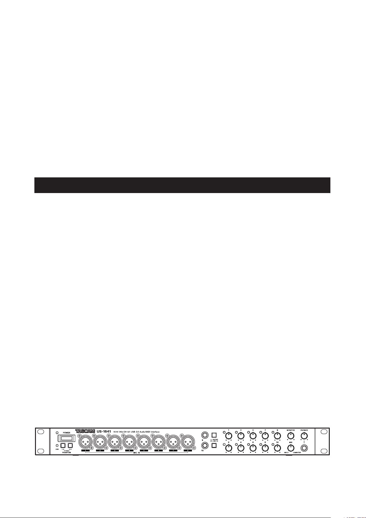
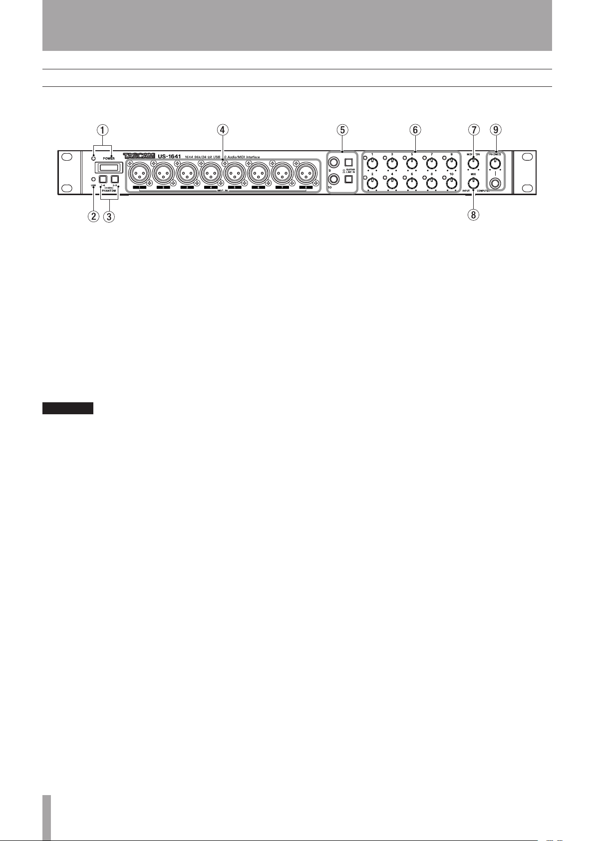
1 POWER switch and indicator Turns the power to
the unit on or off. The POWER indicator lights up red
when the power is on.
2 USB indicator Lights up green to indicate a valid
USB connection to the host computer.
3 PHANTOM [1-4/5-8] switches Turn on the +48V
phantom power supplied to the MIC IN [1-8] jacks.
Each switch turns on the phantom power for four input
channels as a group. The phantom power is on when the
switches are pushed in.
Turn this switch on only if you are using condenser
microphones that require phantom power.
Do not connect or disconnect microphones from the
US-1641 while phantom power is on.
Never supply phantom power to unbalanced
dynamic microphones.
Some ribbon microphones can be damaged by
phantom power. If you are not sure about your
ribbon microphone, do not supply phantom power
to the ribbon microphone.
4 MIC IN [1-8] jacks These are XLR balanced analog
mic input jacks. Use the Gain knobs to adjust the input
gain level.
The wiring is as follows:
pin 1 = ground, pin 2 = hot, pin 3 = cold.
5
LINE IN/GUITAR [9/10] jacks and select switches
These stereo 1/4” phone jacks function as unbalanced
guitar input jacks when the select switches are set to the
GUITAR position, and function as balanced line input
jacks when the switches are set to the LINE IN position.
(The wiring is as follows: sleeve = ground, tip = hot, ring =
cold.) Use the Gain knobs to adjust the input gain level.
6 Gain knobs and indicators [1-10] Adjust the gain
level for Inputs 1-10 individually. The adjustable range
is from –2dBu to –58dBu for Mic Inputs 1-8, and from
+4dBu to +42dBu for Line Inputs 9-10. The Gain indi-
cators will light green when a signal at a certain level
(–30dBFS) or higher is present. However, if the signal level
exceeds –2dBFS, the indicators will light red.
7 MONITOR knob Adjusts the level of signals output
from the MONITOR OUTPUTS [L/R] jacks on the rear
panel.
8 MIX knob Controls the balance of the signal sources
being output from the MONITOR OUTPUTS [L/R] jacks
and the PHONES jack. With this knob turned to the far
left, the US-1641 will output the signal input from the MIC
IN [1-8] jacks and LINE IN [9-14] jacks. With this knob
turned to the far right, the US-1641 will output the signal
received from the computer via USB.
9 PHONES jack and PHONES LEVEL knob This
stereo 1/4" headphone jack outputs the same signal that is
output from the MONITOR OUTPUTS [L/R] jacks. The
PHONES LEVEL knob controls the output level of the
PHONES jack.
8 TASCAM US-1641
8 TASCAM US-1641
Page 9
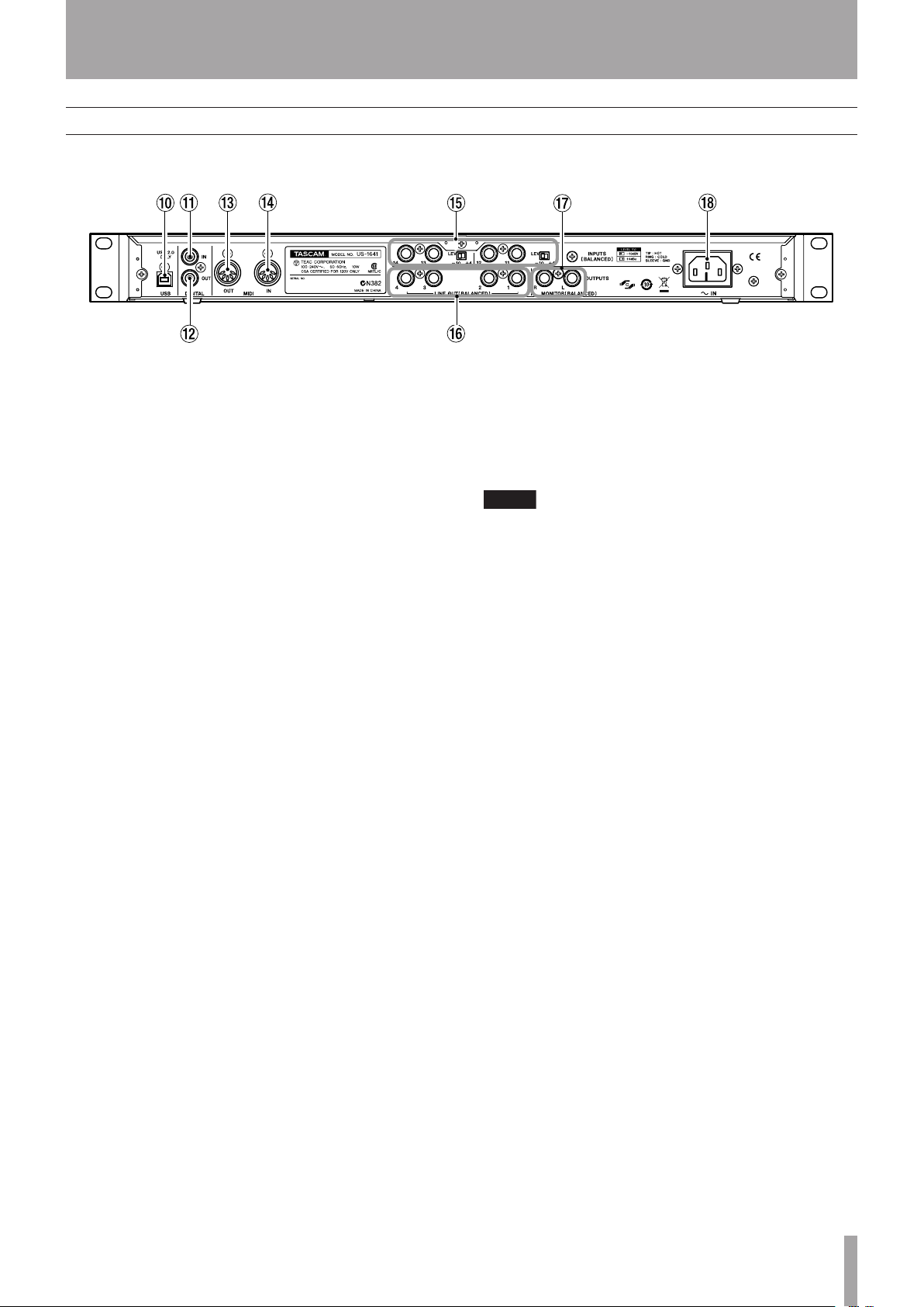
Rear Panel
NOTE
IMPORTANT SAFETY INSTRUCTIONS
2 – Features of the US-1641
0 USB connector Use a USB cable to connect this to
the host computer. (Please note that this connector supports
only USB 2.0 connection.)
A DIGITAL IN jack This is an RCA connector that
inputs a stereo S/PDIF digital signal.
B DIGITAL OUT jack This is an RCA connector that
outputs a stereo digital signal. Signals output from the
LINE OUT [1/2] or [3/4] jacks can be output digitally from
this jack (as set in the Control Panel). You can also select
S/PDIF or AES/EBU as the digital signal format in the
Control Panel.
C MIDI OUT connector Transmits MIDI messages
received from the computer.
D MIDI IN connector Receives MIDI messages.
The received MIDI messages will be transmitted to the
computer.
E INPUTS [11-14] jacks and LEVEL switches These
are TRS 1/4" phone, balanced line input jacks. Use the
LEVEL switches to set the nominal level to –10dBV or
+4dBu.
You cannot adjust the gain level for these inputs.
F LINE OUT [1-4] jacks These are stereo TRS 1/4"
phone, balanced line output jacks (sleeve = ground, tip =
hot, ring = cold). The nominal output level is +4dBu. These
jacks output signals received from the computer. Use DAW
software to switch between LINE OUT [1/2] and LINE
OUT [3/4].
G MONITOR OUTPUTS [L/R] jacks These are stereo
TRS 1/4" phone, balanced output jacks (sleeve = ground,
tip = hot, ring = cold). These jacks enable you to monitor
monaural mix input (1-14) signals and/or output signals
received from the computer. Use the MONITOR knob on
the front panel to adjust the output level.
H AC IN connector Connect the supplied power cable
to this connector and an AC outlet.
TASCAM US-1641 9
TASCAM US-1641 9
Page 10

IMPORTANT SAFETY PRECAUTIONS
NOTE
3 – Installation
3 – Installation
System requirements
Windows
Supported operating system:
32-bit Windows XP SP2 or 32-bit Vista
Recommended system:
CPU: Pentium4 or Athlon 1.4 GHz or faster (or equiva-
•
lent processor)
RAM: 512 MB or more memory
•
HDD: 1 GB or more free space
•
USB 2.0 port
•
DVD-ROM drive to install Cubase LE 4
•
Internet connection to activate Cubase LE 4
•
These requirements must be satisfied if you plan to use
Cubase LE 4 (bundled with the US-1641). If you are planning to use other application software, please consult
its technical documentation for operating requirements
specific to that software.
The number of available audio tracks will depend on
the speed of your hard disk. A faster hard disk will
facilitate smoother and easier operation.
USB1.1 is not supported.
TASCAM recommends that you use a system with
at least 512 MB of memory. However, additional
memory will enhance the operation of digital audio
application software.
This product has been tested for use with typical
computers that meet the operating requirements
listed above. However, the test results do not guarantee that the product will operate properly with
every computer that meets these requirements.
Please be aware that even under similar conditions,
processing capabilities may vary depending on the
particular design and specifications of the computer
and the operating environment.
Mac OS X
Supported operating system:
Mac OS X version 10.4 or later
Recommended system:
CPU: Power PC G4 1GHz or higher, Core Solo 1.5GHz
•
or higher
RAM: 512 MB
•
HDD: 1 GB or more free space
•
USB 2.0 port
•
Audio device that supports Core Audio
•
DVD-ROM drive to install Cubase LE 4
•
Internet connection to activate Cubase LE 4
•
For Macintosh systems as well, additional memory and a
faster hard disk drive will facilitate smoother and easier
operation of digital audio application software.
10 TASCAM US-1641
10 TASCAM US-1641
Page 11
IMPORTANT SAFETY INSTRUCTIONS
NOTE
CAUTION
WARNING
Installing the drivers
Before you can use the US-1641, you must install the
appropriate drivers on your computer. As described below,
this is a simple process that uses the CD-ROM included
with the US-1641.
Drivers are updated from time to time. You can download
the latest version of the drivers from the TASCAM website
<http://www.tascam.com/>.
3 – Installation
Handle the enclosed CD-ROM with care. If the disc
becomes scratched or dirty, your computer may be
unable to read it and you may be unable to install
the software.
If the disc becomes unreadable, you can request a
replacement disc for a fee.
Do not connect the US-1641 to your computer before you
install the drivers.
Installing the drivers for Windows
The US-1641’s drivers are provided on the CD-ROM as an
executable installer.
You can download the latest version of the drivers from the
TASCAM website <http://www.tascam.com/>. If the drivers on the CD-ROM are not the latest version, TASCAM
recommends that you download the latest version of the
drivers from the website and install them.
Installation procedure
This section provides detailed procedures for installing the
Windows XP driver software from the included CD-ROM
and updating the firmware for the US-1641.
During installation, you must connect, disconnect, then reconnect the USB cable to the unit as
described in steps 7, 8, and 9.
Complete each installation step within one minute of the
display of the corresponding instruction. If you take too
much time, the installer may report an error and quit. If
this occurs, simply run the installer again.
Never attempt to play the enclosed CD-ROM in an
audio CD player. The resulting noise could damage
your speakers or your hearing.
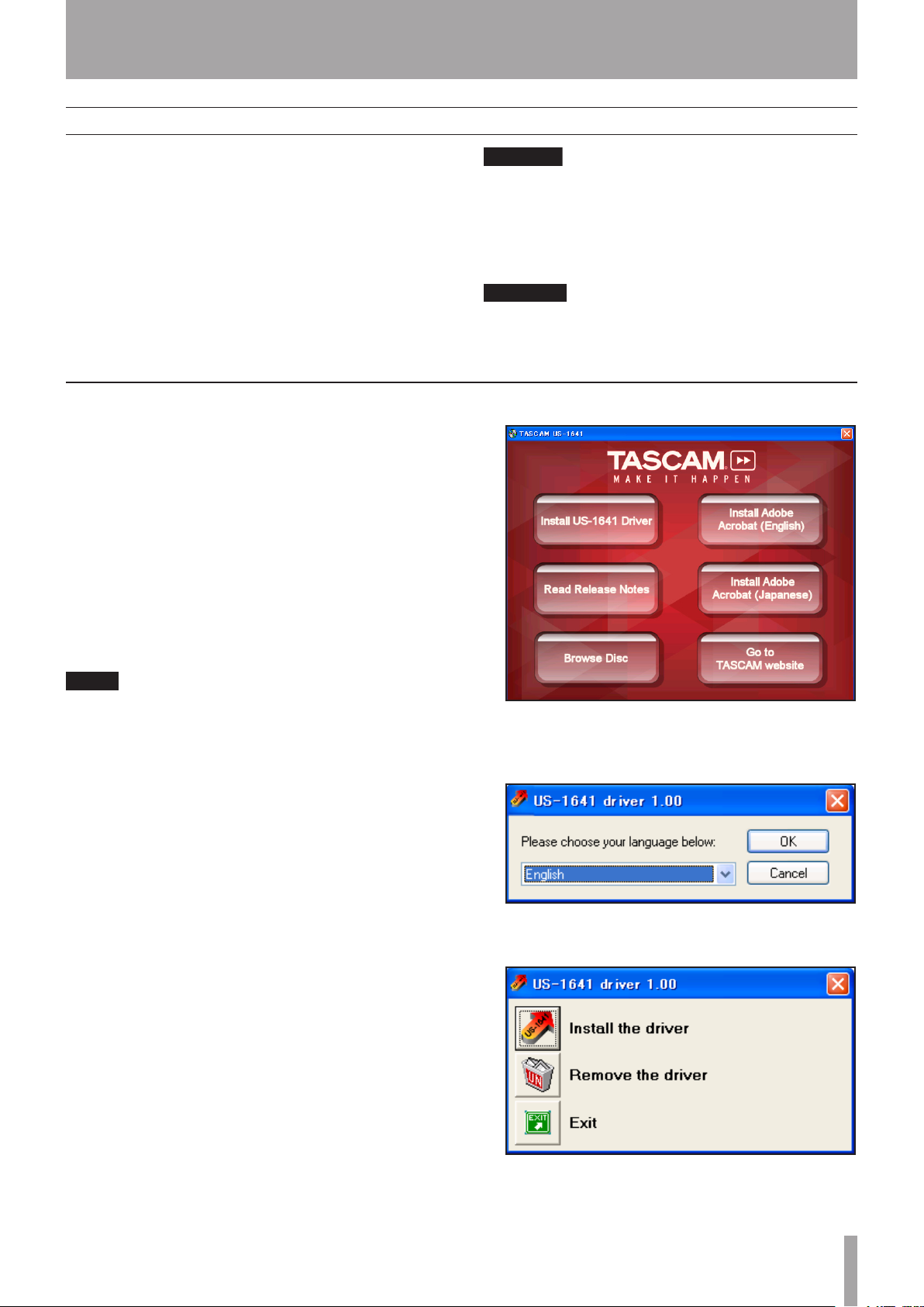
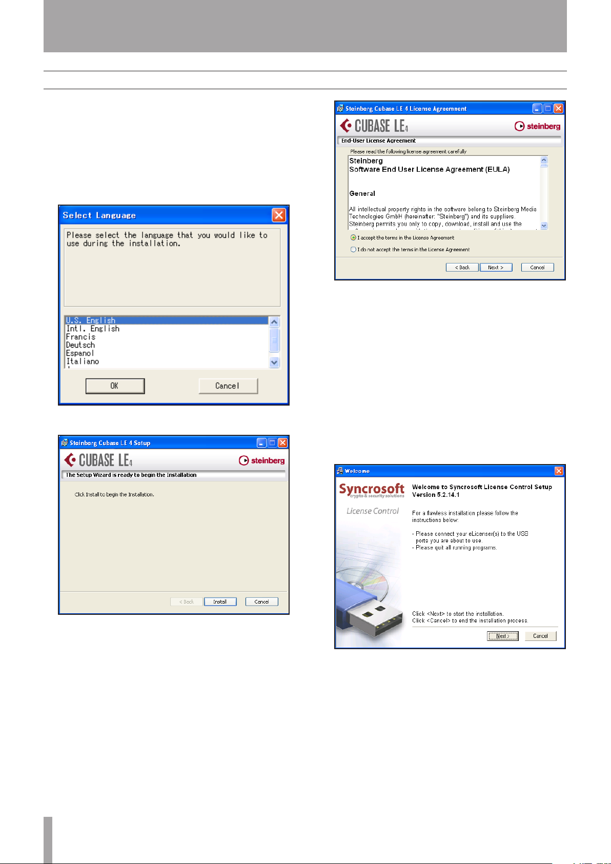
When the language selection screen (below) appears,
4�
select the language you prefer, then click the OK
button.
Installing the drivers
Make sure that the US-1641 is not connected to your
1�
computer via a USB cable.
Insert the included driver installation CD-ROM
2�
into the CD-ROM drive on your computer.
Click the Install US-1641 Driver button when the
3�
menu screen below appears.
If this screen does not appear automatically, find
and open the Autorun Menu.exe program on the
driver CD-ROM.
When the screen below appears, click the
5�
Install the driver button.
TASCAM US-1641 11
TASCAM US-1641 11
Page 12
IMPORTANT SAFETY PRECAUTIONS
3 – Installation
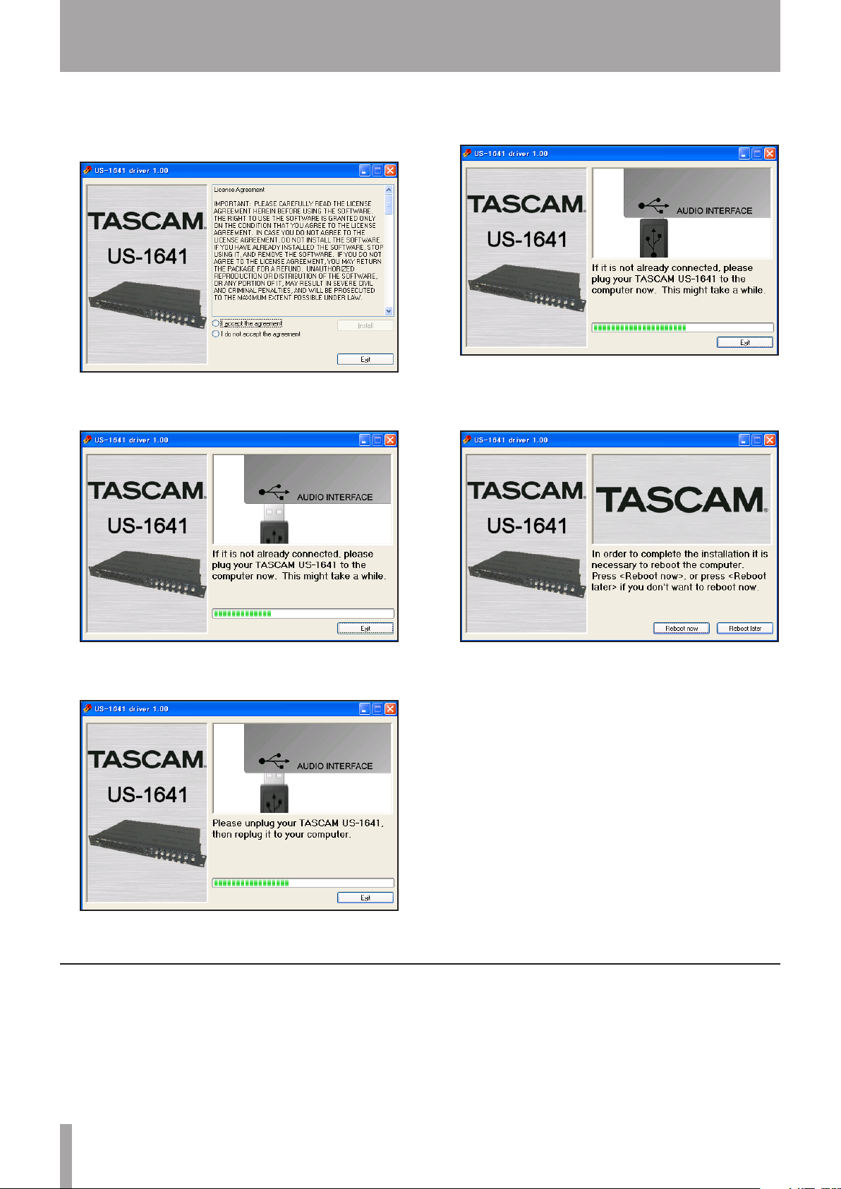
Read the contents of the License Agreement, then
6�
select I accept the agreement if you agree to the
terms. Click the Install button to start installation.
When the screen below appears, use the supplied
7�
USB cable to connect the US-1641 to the computer.
When the screen below appears, reconnect the
9�
US-1641 to the computer with the USB cable.
When the screen below appears, the installation is
10�
complete. Click the Reboot now button to restart
the computer.
When the screen below appears, unplug the connect-
8�
ing USB cable from the US-1641 or the computer.
Installing the drivers for Mac OS X
1�
Insert the included driver installation CD-ROM
into your computer’s DVD-ROM drive, then doubleclick US-1641 Drivers.mpkg on the CD-ROM to
start the installer.
After the computer has restarted, select Start >
11�
Settings > Control Panel, then click TASCAM US1641 Control Panel to open the US-1641 Control
Panel. If the driver version, device name and other
data appear to be correct, the installation was
successful.
Follow the instructions on screen.
2�
Restart the computer, then use the USB cable to
3�
connect the US-1641 to the computer.
12 TASCAM US-1641
12 TASCAM US-1641
Page 13
IMPORTANT SAFETY INSTRUCTIONS
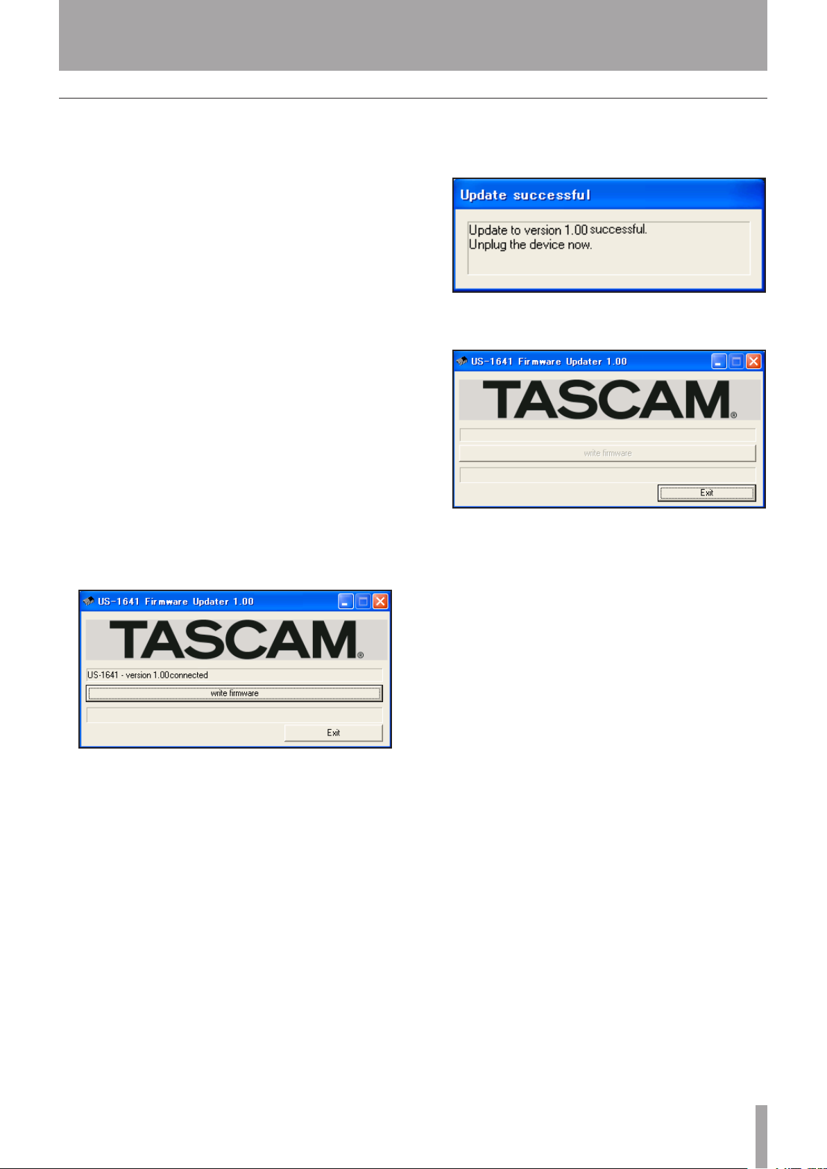
Updating the firmware for the US-1641
3 – Installation
TASCAM may release updates for the software that runs
on the microchip inside the US-1641. This is commonly
called “firmware”. When your US-1641 is plugged into the
computer, the US-1641 Control Panel shows what firmware
version the unit is currently running. Visit TASCAM’s
website (http://www.tascam.com) to see if a newer version
of the firmware is available. If so, you can download a
firmware updater program for you computer that will
update your US-1641’s firmware.
Preparation Step 1:
Install the latest driver on your PC or Mac computer.
Preparation Step 2:
Connect the US-1641 (for which firmware will be updated)
to the computer via a USB cable.
The firmware updater varies with the firmware version
*
of the unit.
For PC (Windows XP) users
Connect the US-1641 to the computer via a USB
1�
cable.
Run the firmware updater file (for PC) for the
2�
version to which you wish to update.
The system displays the following screen:
When the update process is complete, the system
4�
displays the following screen:
Disconnect the USB cable from the US-1641.
5�
The system displays the following screen:
Click the Exit button to complete the update opera-
6�
tion.
For Mac (OS X) users
Connect the US-1641 to the computer via a USB
1�
cable.
Click the write firmware button.
3�
Run the firmware updater file (for Mac) for the
2�
version to which you wish to update.
Follow the steps for Windows PCs as described
3�
above. The screens displayed may appear slightly
different from those shown above, but their content
is essentially the same.
TASCAM US-1641 13
TASCAM US-1641 13
Page 14
IMPORTANT SAFETY PRECAUTIONS
3 – Installation
Installing Cubase LE 4
Insert the Cubase LE 4 DVD-ROM into the
1�
DVD-ROM drive on your computer.
The system displays the language selection screen
(below). Select the language you prefer.
If this language screen does not appear automatically, run the Setup.exe program in the \Cubase LE
4 for Windows directory on the DVD-ROM.
The system displays the installation destination
4�
screen. Browse and specify the destination for
installation, then click the Next button.
Click the Install button.
2�
The system displays the License Agreement for end
3�
users. Read the contents, then select I accept the
tems in the License Agreement if you agree to the
terms. Click the Next button.
The system displays a screen indicating that it is
5�
ready to install the application. Click the Install
button.
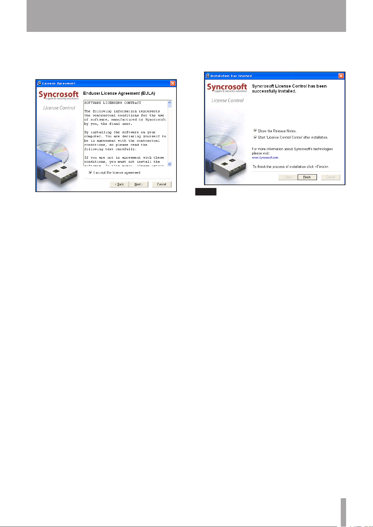
Syncro Soft installer starts. Select a language for the
6�
installation process.
The system displays the Syncro Soft Welcome
7�
screen. Click the Next button to start the installation.
14 TASCAM US-1641
14 TASCAM US-1641
Page 15
IMPORTANT SAFETY INSTRUCTIONS
NOTE
The system displays the License Agreement for end
8� The system displays a screen indicating that the
users. Read the contents, then select I accept the
license agreement if you agree to the terms. Click
the Next button.
9�
Syncro Soft installation is complete. Click the Finish
button to finish the installation procedure.
When you start Cubase LE 4 for the first time, you
will be asked to register the software on-line. If you
do not register the software, you will be unable to
use it beyond 30 days after you install the program.
TASCAM recommends that you register the software
at your earliest convenience.
3 – Installation
TASCAM US-1641 15
TASCAM US-1641 15
Page 16

IMPORTANT SAFETY PRECAUTIONS
3 – Installation
Settings on your computer
Here are a few basic points to help you set up your computer
for best performance with audio applications.
Do not run other applications. You will probably use
•
your computer for applications other than audio, but
TASCAM recommends that you avoid running other
applications at the same time you are running audio
programs. Processing digital audio places a considerable load on your computer. This means that if you
are running other applications (especially graphics or
Internet tools) at the same time as your audio application, processing may not be fast enough.
Certain devices such as network cards or WinModems
•
can cause conflicts with USB operation. If you experience such a conf lict, you can use the Device Manager to
temporarily disable the offending device.
You can also improve the audio processing capability or
increase the number of recording and playback tracks on
your computer by upgrading or expanding the computer
hardware.
16 TASCAM US-1641
16 TASCAM US-1641
Page 17

Overview
IMPORTANT SAFETY INSTRUCTIONS
4 – Control Panel settings
The US-1641 Control Panel enables you to control various
features of the US-1641. It also reports the status of the
driver and the currently connected unit.
In Windows XP, you can access US-1641 Control Panel
shortcut from the following:
Start menu
•
Window’s Control Panel
•
All Programs > TASCAM > US-1641 Control Panel
•
In Mac OS X, US-1641 Control Panel is located in the
Application folder. Audio MIDI settings, which is used for
audio and MIDI settings, is located in the Utility folder in
the Application folder.
Driver settings
Audio Performance (Windows PC case)
The US-1641 driver temporarily stores input and output
audio samples in buffers.
The Audio Performance setting enables you to adjust the
buffer size to five levels. The Lowest Latency setting is
the minimum buffer size, and the Highest Latency setting
is the maximum buffer size.
A smaller buffer size will reduce the audio signal delay
when you monitor the input signal, but will require your
computer to perform the processing faster. If the processing does not occur in time (e.g., if the computer is performing other system operations), you may notice clicks, pops,
or dropouts in the audio signal.
The US-1641 Control Panel is divided into two sections:
Status section
This section indicates the current status of the driver and
the connected hardware. You cannot edit the settings in
this section.
Setting section
This section enables you to control various settings of the
US-1641.
A larger buffer size will provide more stable operation and
more safety against such problems caused by other system
activities, but will produce greater delay in monitoring
signals.
Select the buffer size that works best for your system.
For Mac computer users:
Mac’s control panel does not have Audio Performance on
it. Instead of Audio Performance, each DAW has audio
buffer setting which is based on sample step. That works as
the same as Audio Performance.
Sample Clock Source
You can set the clock source to Automatic or Internal.
Automatic (default): If a signal is being input to the
DIGITAL IN jack, its clock will be used. If no signal is
being input to the DIGITAL IN jack, the US-1641’s internal
clock will be used.
Digital Output Format
This setting enables you to choose either AES/EBU or
S/PDIF as the digital output format.
Digital Output Channels
The DIGITAL OUT jack outputs signals from either Line
out 1 and 2 or Line out 3 and 4. This setting enables you
to select one of these output channel pairs.
Internal: The US-1641’s internal clock will always be used.
TASCAM US-1641 17TASCAM US-1641 17
Page 18
IMPORTANT SAFETY PRECAUTIONS
NOTE
NOTE
V
ocal
microphone
Drums
Guitar
Headphones
Bass guitar
Microphones
External
mic amp
Powered speakers,
or amp and speakers
Microphones
Sound module,
CD player, etc.
USB
Computer
Keyboard
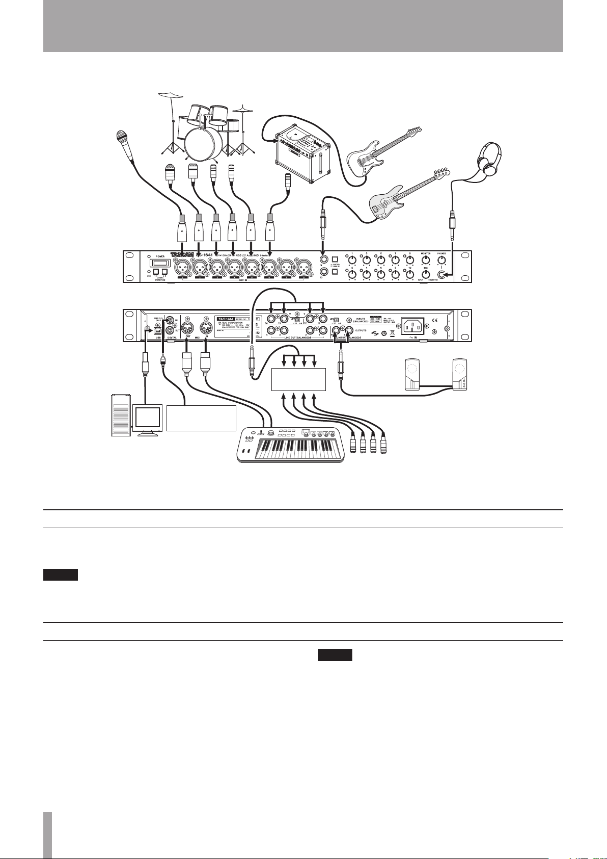
5 – Connections
USB connections
Using the included cable, connect the US-1641 to your
computer as shown in the illustration.
Some USB devices access the USB bus frequently. To
avoid dropouts and clicks in the audio signal, do not
Audio connections
Connect the output signal of your mic, guitar, keyboard,
or other audio device to the US-1641, which will convert
the signal into digital audio and send it via USB to your
computer. Connect the output of the US-1641 to your
speakers (via an amp) or headphones, so you will be able
to monitor the audio signals coming into the US-1641 or
signals being output from your computer.
Mic
Connect your microphones to the MIC IN [1-8] jacks
(XLR). If you are using a condenser microphone that
requires phantom power, turn on the phantom power.
18 TASCAM US-164118 TASCAM US-1641
connect other USB devices to the USB bus used by
the US-1641.
USB keyboards and mouse are exceptions to this, and
will probably not cause problems.
You can use more than eight microphones by
connecting them via an external mic pre-amp. In this
case, connect the output of the mic pre-amp to the
LINE IN [11-14] jacks on the rear panel.
Guitar
Connect your electric guitar and base guitar to the LINE
IN/GUITAR [9-10] jacks and set the GUITAR-LINE IN
switch to GUITAR.
Page 19

IMPORTANT SAFETY INSTRUCTIONS
NOTE
NOTE
Keyboard/drum machine/sound module/ CD player, etc. (analog connection)
Connect the analog audio output of these devices to the
LINE IN/GUITAR [9-10] jacks or INPUTS [11-14] jacks.
If you use the LINE IN/GUITAR [9-10] jacks, set the
GUITAR-LINE IN switch to LINE IN.
If you use the LINE IN/GUITAR [9-10] jacks, you can
adjust the input gain levels continuously from –6dBv
to –52dBv. If you use the INPUTS [11-14] jacks, you
can switch the nominal level between –10dBv and
+4dBu.
Sound module/CD players, etc. (digital connection)
Connect the digital audio output of these devices to the
DIGITAL IN jack.
MIDI connections
5 – Connections
The US-1641 DIGITAL OUT jack outputs either S/PDIF
or AES/EBU signals (selectable in the US-1641 Control
Panel). On the other hand, you can input S/PDIF
signals to the DIGITAL IN jack.
Headphones
Connect a set of stereo headphones to the PHONES jack
(1/4” stereo phone jack).
Powered speakers/audio system
Connect powered monitoring speakers or audio system to
the MONITOR OUTPUTS [L/R] jacks.
Connect your sound module, keyboard/synthesizer, drum
machine, or other MIDI device to the US-1641 as shown in
the illustration on page 17.
The US-1641 receives MIDI signal at the MIDI IN connec-
tor, then transmits it to the connected computer. Also, the
US-1641 receives MIDI signal from the computer, then
transmits it from the MIDI OUT connector. In this way,
you can use the MIDI IN/MIDI OUT connectors to trans-
mit and receive MTC (MIDI Time Code). This allows the
MTC-compatible MTR (Multi Track Recorder) of your
DAW (Digital Audio Workstation) computer application to
synchronize with your MIDI equipment.
TASCAM US-1641 19
TASCAM US-1641 19
Page 20

IMPORTANT SAFETY PRECAUTIONS
NOTE
6 – Recording with Cubase LE 4
This chapter explains basic operations for using the US-1641
with Cubase LE 4.
Input setting
Start Cubase LE 4. From the Devices menu, choose
1�
Device Setup.
The system displays the Device Setup window.
In the VST Audio System section in the right side of
2�
the Device Setup window, select US1641 for ASIO
Driver.
This explanation is not intended to replace the user’s manual
for Cubase LE 4. For more information on Cubase LE 4,
please refer to the Cubase LE 4 user’s manual.
Select the Outputs tab, then set the output bus.
5�
When you set the output bus, a device port is automatically selected. If necessary, you can change the
device port. The device port pull-down list indicates
all available output ports for the US-1641.
From the Devices menu, choose VST Connection.
3�
The system displays the VST Connections window,
which features two tabs: Input and Output.
Select the Inputs tab, then set the input bus.
4�
When you set the input bus, a device port is automatically selected. If necessary, you can change the
device port. The device port pull-down list indicates
all available input ports for the US-1641.
From the File menu, choose New Project.
6�
The system displays a window that enables you to
select a template for your new project. Select the
desired template and press the OK button. The
system displays the Select directly window. Specify
the directory in which you wish to save the project,
then click the OK button. The new project will be
created.
If you have selected an Empty template, add audio
tracks to the project by selecting Add Tracks from
the Project menu.
You are now ready to begin recording.
20 TASCAM US-164120 TASCAM US-1641
Page 21
IMPORTANT SAFETY INSTRUCTIONS
6 – Recording with Cubase LE 4
Recording
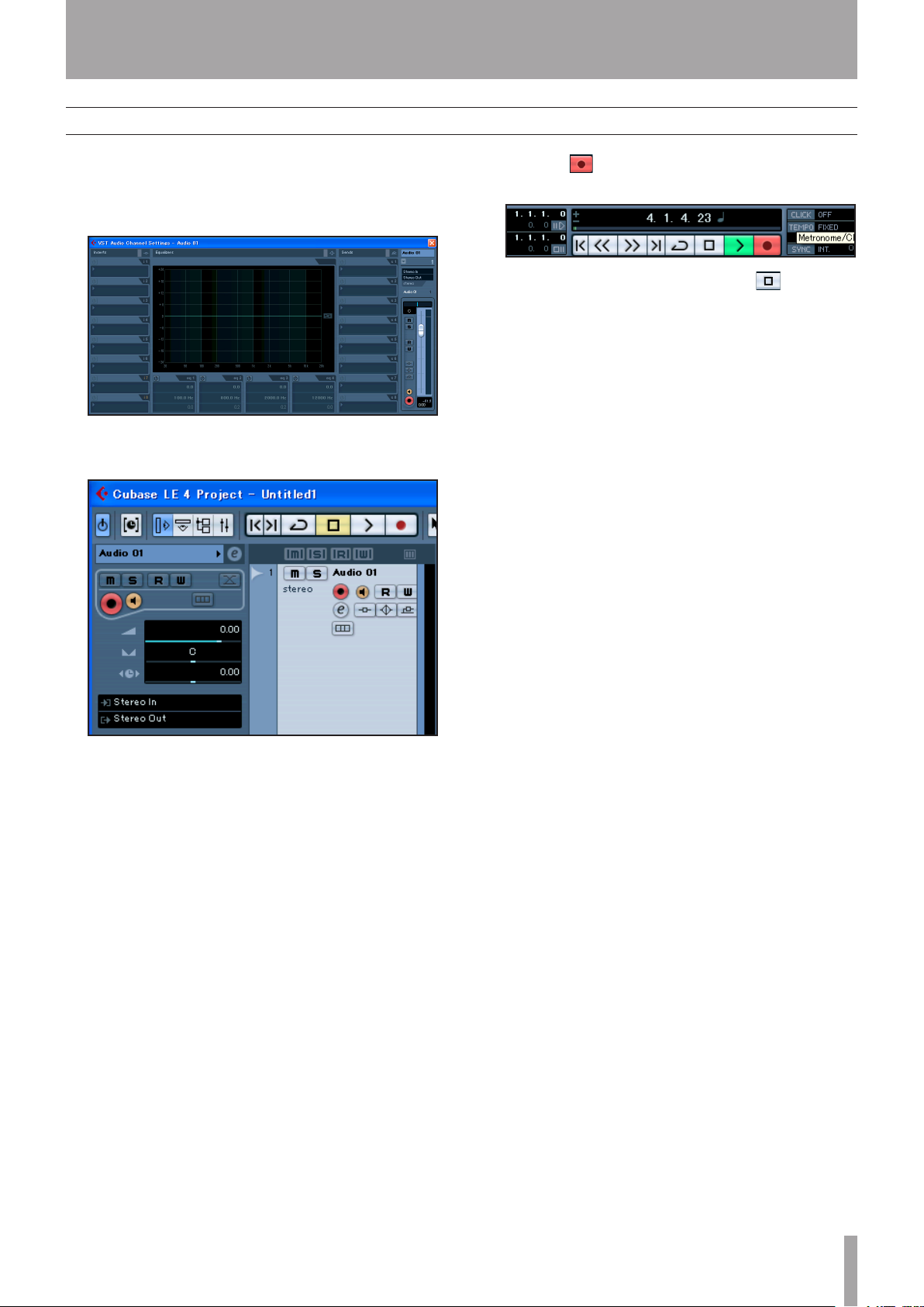
Click the Edit Channel Settings button for the track
1�
you want to record to open the Channel Setting
window. Then, specify the desired input bus in the
Input field located in the upper-right corner.
Click the REC FUNCTION button to turn it on (the
2�
button indicator will light).
Press the (REC) button in the transport section
3�
to start recording.
When you finish recording, press the (STOP)
4�
button, then click the REC FUNCTION button to
turn it off (the button indicator will turn off).
Rewind if necessary.
Repeat steps 1, 2, and 3 to overdub additional
5�
tracks.
TASCAM US-1641 21
TASCAM US-1641 21
Page 22
IMPORTANT SAFETY PRECAUTIONS
6 – Recording with Cubase LE 4
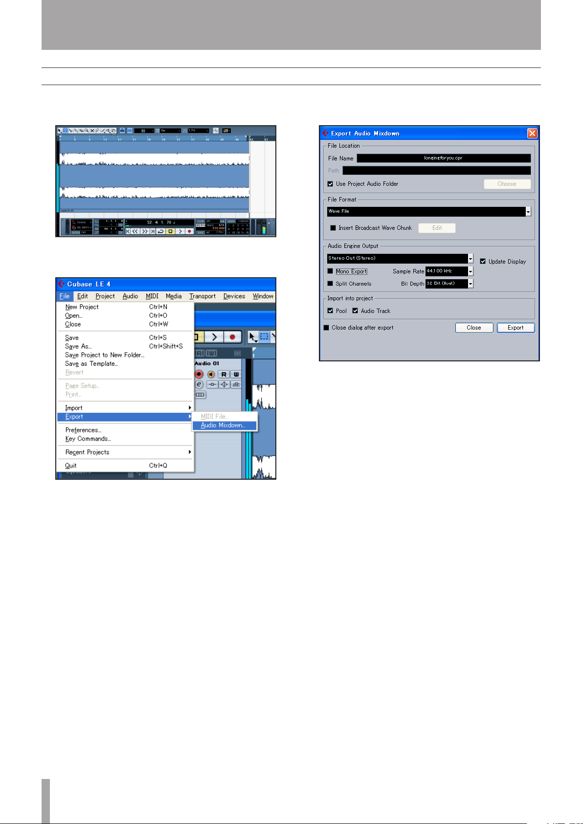
Mixdown
Move the left and right locators to specify the region
1�
that you want to mix down.
From the File menu, choose Export > Audio
2�
Mixdown.
In the Export Audio Mixdown dialog box, make the
3�
desired settings, then press the Export button.
22 TASCAM US-1641
22 TASCAM US-1641
Page 23
IMPORTANT SAFETY INSTRUCTIONS
7 – Troubleshooting
7 – Troubleshooting
This chapter answers frequently asked questions related to
recording with Cubase LE 4.
Q1. I think I have configured the input settings
properly, but I see no activity on the audio
track's meter.
A1. Make sure that the Monitor button of the track is
enabled.
Q2. I would like to record two channels simultaneously in stereo.
A2. Before you record, choose Stereo track(s) or add
Audio track(s) as Stereo. In this case, the track input is
indicated as Stereo in or something similar.
Q6. I burned a CD using the WAV file I mixed
down, but the speed is obviously different.
A6. Could the sampling rate of your project be set to
48 kHz? If your ultimate objective is to create a CD,
TASCAM recommends that the sampling rate be set to
44.1 kHz from the beginning.
To specify the sampling rate, choose Project Settings
from the Project menu, then set the sampling rate to
44.100 kHz.
Q3. I am trying to use the EQ, but it does not
seem to do anything.
A3. Check the VST channel setting or other settings to
make sure that EQ bypass is disabled.
Q4. I tried to mix down a three-minute song,
but could mix only ten seconds.
A4. Make sure that the region specified by the left and
right locators is set to three minutes or longer.
Q5. I cannot set the locator region to more
than ten minutes.
A5. The default setting is ten minutes. From the Project
menu, choose Project Setup and then change the Length
field.
Q7. I have connected an audio source to the
US-1641, but cannot hear anything.
A7. Make sure that the input level is raised appropriately.
When a signal is being input, the Gain indicator will light
up green. Make sure that the monitor (or headphone) level
is raised, and that the connections are correct.
Q8. The sound is distorted.
A8. Make sure that the signal is not overloading. If the
signal is analog, the ideal level is when the Gain indicator
lights up red occasionally.
Q9. I tried to change the sample rate in the
Control Panel, but could not.
A9. If a valid signal is plugged into the US-1641’s digital
input, and the Sample Clock Source menu has been set to
Automatic, the US-1641 will always run at the sample rate
received at its digital input. To run at a different sample
rate while continuing to receive digital audio, you must
change the sample rate of the device that is sending the
digital signal. If you do not need to continue to receive
digital audio, you can set the Sample Clock Source menu
to Internal or simply unplug the cable connected to the
digital input.
TASCAM US-1641 23
TASCAM US-1641 23
Page 24

IMPORTANT SAFETY PRECAUTIONS
8 – Specifications
8 – Specifications
Inputs and outputs
MIC IN [1-8] jacks (analog)
Connector XLR-3-31
Type and wiring Balanced (1: ground, 2: hot, 3: cold)
Input impedance
Input level (with the
Input level (with the
Headroom 16dB
LINE IN/GUITAR [9-10] jacks (analog)
Connector 1/4” phone jack
[With the
[With the
LINE IN-GUITAR
Type and wiring Balanced (Tip: hot, Ring: cold, Sleeve: ground)
Input impedance
Nominal input level (with the
Nominal input level (with the
Headroom 16dB
LINE IN-GUITAR
Type Unbalanced
Input impedance
switch set to
switch set to
Gain knobs
Gain knobs
LINE IN
GUITAR
set at maximum)
set at minimum)
]
Gain knobs
Gain knobs
]
set at maximum)
set at minimum)
2.2k
Ω
–58dBu
–2dBu
10k
Ω
–42dBu
+4dBu
700k
Ω
Nominal input level (with the
Nominal input level (with the
Headroom 6dB
INPUTS [11-14] jacks (analog)
Connector 1/4” phone jack
Type and wiring Balanced (Tip: hot, Ring: cold, Sleeve: ground)
Input impedance
Nominal input level (selectable with the
Headroom 16dB
DIGITAL IN jack (digital)
Connector RCA pin jack
Signal format IEC958 Consumer (S/PDIF)
Level
Gain knobs
Gain knobs
set at maximum)
set at minimum)
LEVEL
switch)
–52dBv
–6dBv
10k
Ω
+4dBu or –10dBv
0.5Vpp/75
Ω
24 TASCAM US-1641
24 TASCAM US-1641
Page 25
IMPORTANT SAFETY INSTRUCTIONS
DIGITAL OUT jack (digital)
Connector RCA pin jack
Signal format Selectable in the Control Panel between IEC958 Consumer
Level
LINE OUT [1-4] jacks (analog)
Connector 1/4” phone jack
Type and wiring Balanced (Tip: hot, Ring: cold, Sleeve: ground)
8 – Specifications
(S/PDIF) and IEC958 Professional (AES/EBU)
0.5Vpp/75
Ω
Output impedance
Nominal output level +4dBu
Maximum output level +20dBu
MONITOR OUTPUTS [L/R] jacks (analog)
Connector 1/4” phone jack
Type and wiring Balanced (Tip: hot, Ring: cold, Sleeve: ground)
Output impedance
Nominal output level +4dBu
Maximum output level +24dBu
PHONES jack (analog)
Connector 1/4” stereo phone jack (Tip: L, Ring: R, Sleeve: ground)
Maximum output level
MIDI IN connector
Connector 5-pin Din [Standard MIDI format]
MIDI OUT connector
100
Ω
100
Ω
50mW + 50mW (32Ω/1% distortion)
Connector 5-pin Din [Standard MIDI format]
USB connector
Connector USB Series B connector
Format USB 2.0
General specifications
Sampling rate (internal clock) 44.1kHz, 48kHz, 88.2kHz, 96kHz
Sample width 24-bit
External dimensions (W x D x H) 482.6 x 280 x 44 (mm) / 19 x 11.1 x 1.74 (in)
Weight 3.2kg / 7.1lb
Power U.S.A./Canada 120V AC, 60Hz
Power consumption 10W
U.K./Europe 230V AC, 50Hz
Australia 240V AC, 50Hz
TASCAM US-1641 25
TASCAM US-1641 25
Page 26

IMPORTANT SAFETY PRECAUTIONS
8 – Specifications
Audio performance
Delay
≤
0.63ms (ADC), ≤0.44ms (DAC) (at Fs 44.1kHz)
≤
0.29ms (ADC), ≤0.20ms (DAC) (at Fs 96kHz)
Signal-to-noise ratio
[With
MIX
knob set to
COMPUTER
]
MIC IN [1-8]
LINE IN [9-10]
INPUTS (11-14)
[With
MIX
knob set to
All inputs ->
Frequency response (LINE OUT, –10dBV)
Normal sampling rate 20Hz - 20kHz, +1/–1dB
High sampling rate 20Hz - 40kHz, +1/–3dB
Total harmonic distortion (20Hz - 20kHz)
≤
0.01% (All outputs, minimum gain, maximum input level, excluding
Crosstalk (1kHz)
90dB
->
LINE OUT [1-4]
->
LINE OUT [1-4]
->
MONITOR OUT (L/R)
INPUT
]
MONITOR OUT (L/R)
Host computer compatibility
≤
–60dBu (with
≤
–55dBu (with
≤
–70dBu (with
≤
–60dBu (with
GUITAR IN
Gain knob
Gain knob
MONITOR
Gain knobs
)
set to maximum)
set to maximum)
knob set to maximum)
and
MONITOR
knob set to maximum)
Operating system
Windows 32-bit Windows XP SP2 or 32-bit Vista
Macintosh
Drivers
WDM (KS), ASIO/ASIO2 and GSIF2 interface (Windows XP, Vista)
Core Audio and MIDI interface (Macintosh OS X)
* Microsoft, Windows, and Windows XP are registered trademarks of Microsoft Corporation in the United States of America
and in other countries.
* Athlon is a registered trademark of Advanced Micro Devices, Inc. in the United States of America.
* Pentium is a registered trademark of Intel Corporation in the United States of America.
* MIDI is a registered trademark of Association of Musical Electronics Industry (AMEI) and the MIDI Manufacturers
Association (MMA).
* The name of companies and products described in this manual are trademarks or registered trademarks of the correspond-
ing owners.
Mac OS X version 10.4 or later
26 TASCAM US-1641
26 TASCAM US-1641
Page 27
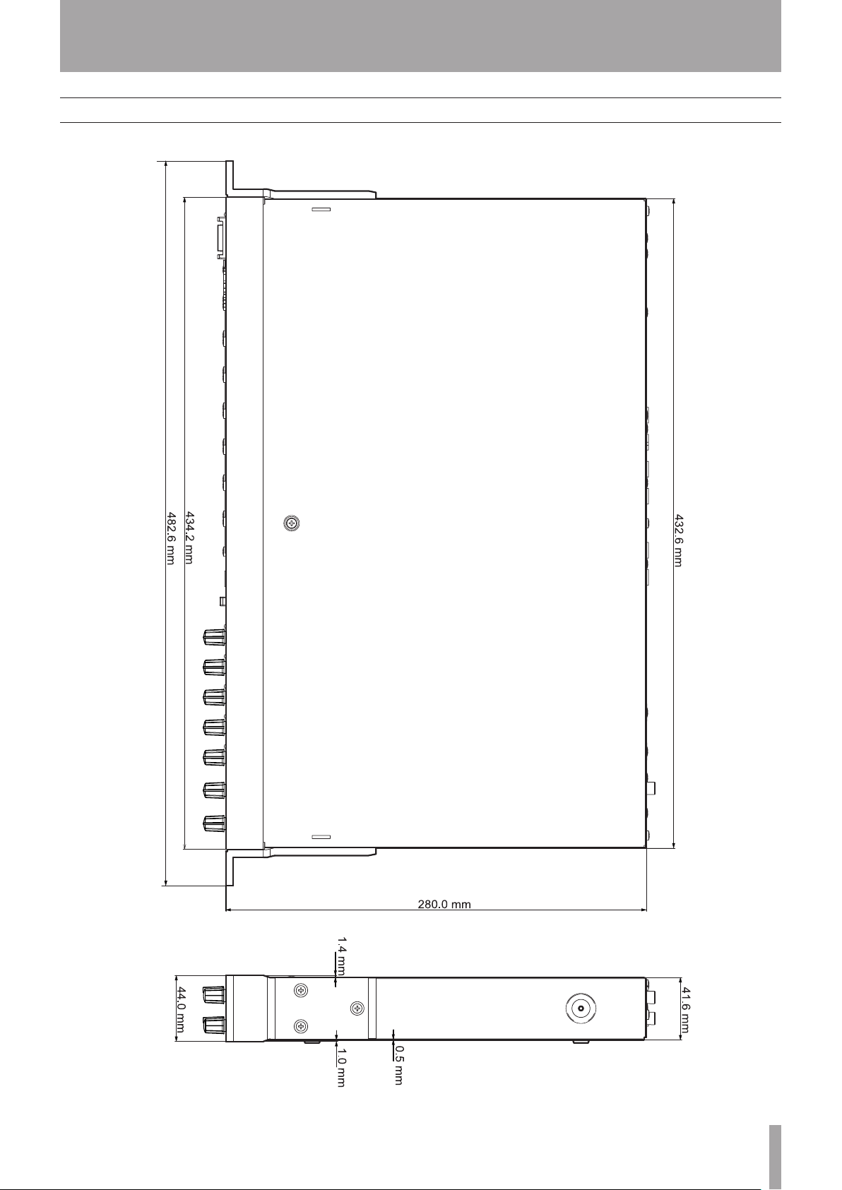
Dimensions
IMPORTANT SAFETY INSTRUCTIONS
8 – Specifications
TASCAM US-1641 27
TASCAM US-1641 27
Page 28

»
US-1641
TEAC CORPORATION
Phone: +81-422-52-5082 www.tascam.com
3-7-3, Nakacho, Musashino-shi, Tokyo 180-8550, Japan
TEAC AMERICA, INC.
Phone: +1-323-726-0303 www.tascam.com
7733 Telegraph Road, Montebello, California 90640
TEAC CANADA LTD.
Phone: +1905-890-8008 www.tascam.com
5939 Wallace Street, Mississauga, Ontario L4Z 1Z8, Canada
TEAC MEXICO, S.A. De C.V
Phone: +52-555-581-5500 www.tascam.com
Campesinos No. 184, Colonia Granjes Esmeralda, Delegacion Iztapalapa CP 09810, Mexico DF
TEAC UK LIMITED
Phone: +44-8451-302511 www.tascam.co.uk
Unit 19 & 20, The Courtyards Hatters Lane, Watford, Hertfordshire. WD18 8TE, U.K.
TEAC EUROPE GmbH
Phone: +49-611-71580 www.tascam.de
Bahnstrasse 12, 65205 Wiesbaden-Erbenheim, Germany
Printed in China
 Loading...