

Page 1

INSTALLING THE
IN A RACK
Both the Tandberg StorageLibrary T24 and the Tandberg StorageLibrary T48 are designed
for installation in a standard 4-post, 19-inch rack.
The Tandberg StorageLibrary T24 uses 2 units (2U) of rack space
The Tandberg StorageLibrary T48 uses 4 units (4U) of rack space
! Important
The rack-mount kit includes the following items:
18 – M5 x 12 Crest Cup™ screws (black) 2 – sets of side support rails
2 – M3 x 8 Crest Cup screws (silver)
8 – washers
Two-post racks will not support either the Tandberg
StorageLibrary T24 or the Tandberg StorageLibrary T48.
(left-side front and back rails and
right-side front and back rails)
BEFORE YOU BEGIN
Select an appropriate location—The maximum recommended ambient temperature for
the library is 40° C (104° F). Install the library in an environment compatible with this
temperature limit. A ventilated rack is recommended.
Ensure that the work area is free from conditions that could cause electrostatic
discharge (ESD). Discharge static electricity from your body by touching a known
grounded surface, such as a computer’s metal chassis.
Ensure that the robot is “parked” and that the shipping key is in place prior to moving
the library. See the Product Manual at www.tandberg.com for instructions.
Obtain the following tools:
#2 Phillips screwdriver Level Tape measure
Copyright 2006 Tandberg Data and Exabyte, EZ17, M2, VXA, and VXAtape are registered trademarks; ExaBotics, MammothTape, and SmartClean are
trademarks; SupportSuite is a service mark. Linear Tape-Open, LTO, the LTO Logo, Ultrium and the Ultrium Logo are trademarks of HP, IBM, and Quantum in
the US and other countries. All other product names are trademarks or registered trademarks of their respective owners.
433679-01 October 2006 www.tandberg.com
Page 2
Warning
Before performing any installation or maintenance procedures, be sure
that the library power switch is in the off position and that the power
cord is disconnected from the library and the outlet.
Warnung
Vor der Ausführung von Installations- oder Wartungsarbeiten ist darauf zu
achten, daß der Library-Netzschalter auf “Aus” gestellt ist und daß das
Anschlußkabel vom Library und der Steckdose entfernt ist.
Advertencia
Antes de realizar cualquier procedimiento de instalación o de mantenimiento, comprobar que el interruptor de alimentación de la biblioteca
está apagado y que el cable de alimentación no está enchufado ni a la
biblioteca ni a la toma de corriente.
ASSEMBLING THE RAILS
1. Measure the depth of your rack—Using a tape measure, measure the inside distance
from the front mounting holes of your rack to the back mounting holes.
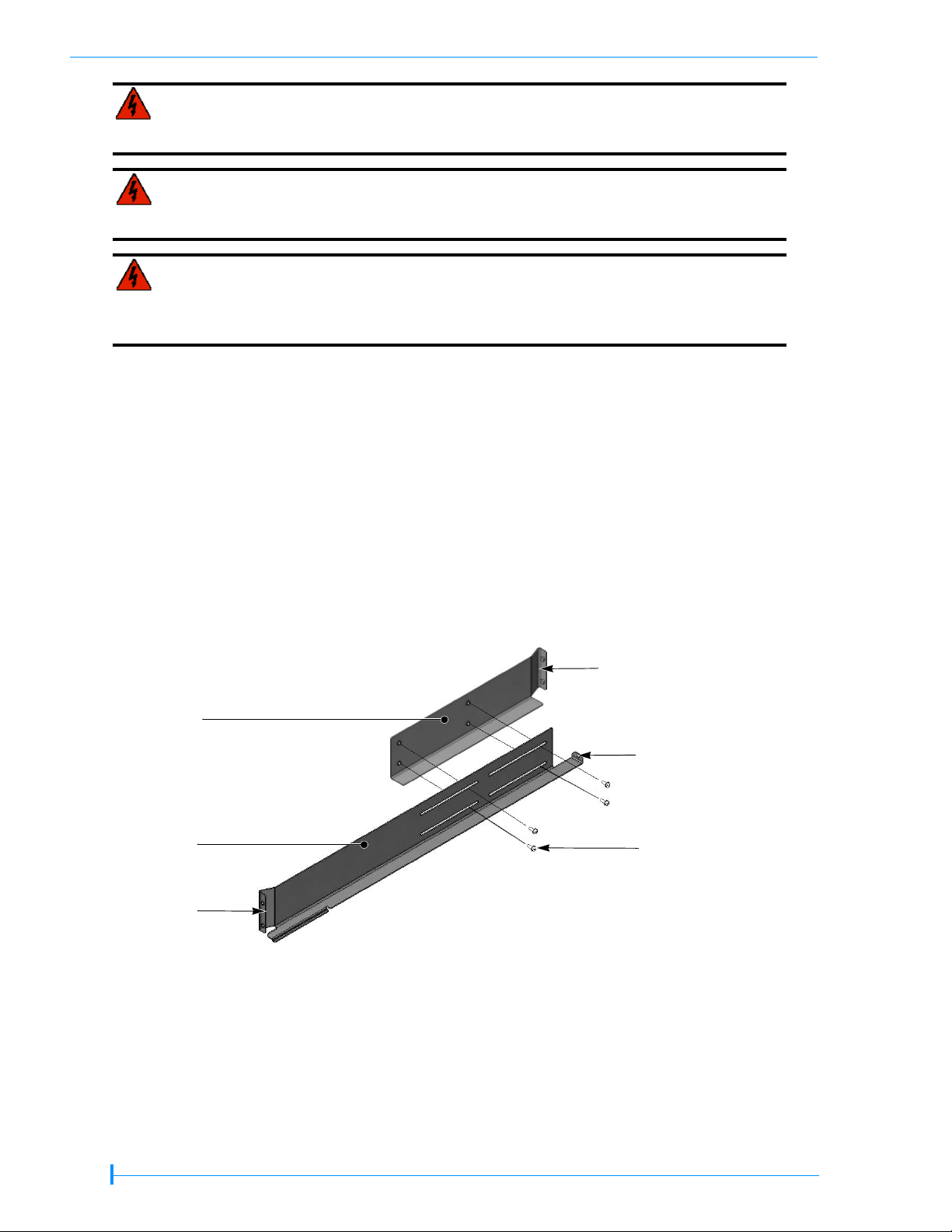
2. Position the front and back sections of the left-side rail as shown in Figure 1, with the
front rail section on top of the back rail section. Spread the sections to the distance you
measured in step 1.
3. Assemble the left rail using four M5 screws, as shown in Figure 1. Keep the screws loose
so that you can adjust the length of the assembled rail, if necessary.
Left-side rails (viewed from front)
Back
section
Front
section
Front
flange
Figure 1 Assembling the left-side rail
Back flange
Small back flange
(attach the library
here in final step)
M5 screw
(black)
2 OF 8
Page 3
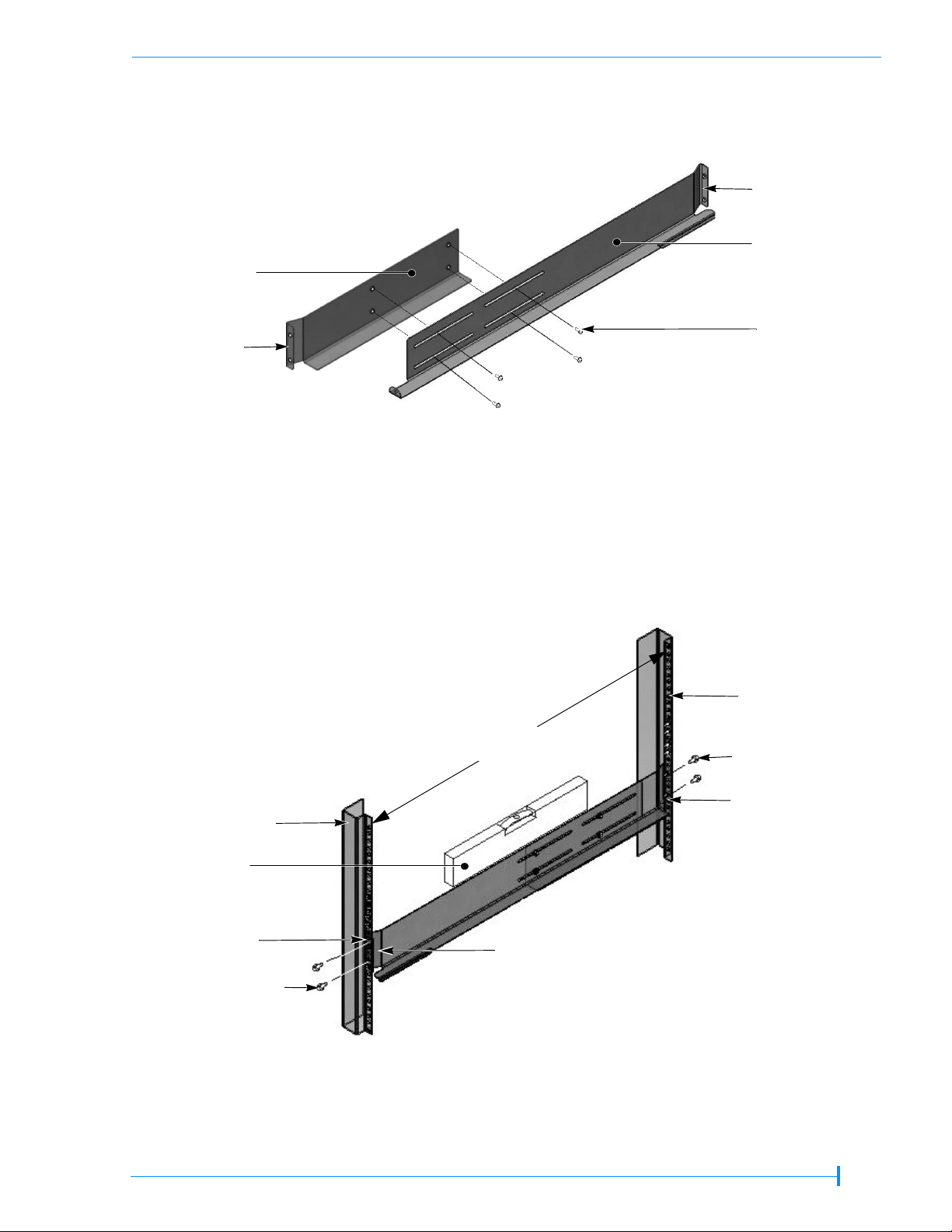
4. Assemble the right-side rail in the same way (see Figure 2).
s
Right-side rails (viewed from the back)
Back
section
Front
flange
Front
section
Back
flange
M5 screw
(black)
Figure 2 Assembling the right-side rail
ATTACHING THE RAILS TO THE RACK
1. Left side rail assembly—Position the left-side rail assembly in the rack so that the front
flange is behind the front screw holes in the rack (see Figure 3).
Back of Rack
Rack rail
(back)
Depth of rack (E)
Rack rail
(front)
M5 screw (A)
(black)
Back
flange (D)
Level
Front rack
screw holes (B)
M5 screw (A)
(black)
Front of Rack
Front flange (C)
Figure 3 Attaching the left-side rail to the rack
3 OF 8
Page 4

2. Front of rack—Insert an M5 screw (A) through one of the front rack screw holes (B) and
engage the pem nut in the rail flange (
holes are much larger than the screws provided in the kit, use a washer. Finger-tighten
the screw.
C). If your rack has square mounting holes or the
Insert an M5 screw (
second screw hole in the rail flange (
screw.
3. Adjust the length of the rail assembly as necessary to fit the depth of the rack (
4. Back of rack—Make sure the rail assembly is level, then use M5 screws (
back flange (
If your rack has square mounting holes or the holes are much larger than the screws
provided in the kit, use a washer. Finger-tighten the screws.
5. Using a #2 Phillips screwdriver, tighten the screws securing the rails to the front and
back of the rack.
6. Using a #2 Phillips screwdriver, tighten the four screws holding the rail assembly
together.
7. Right side rail assembly—Repeat steps 1 through 6 for the right-side rail assembly.
Make sure that the right rail assembly is at the same level as the left rail assembly.
D) of the rail to the inside of the rack, using the same procedure as step 2.
A) through a second screw hole (B) and engage the pem nut on the
C). If necessary, use a washer. Finger-tighten the
E).
A) to attach the
ATTACHING THE LIBRARY TO THE RAILS
To attach the library to the rails:
1. From the front of the rack, place the library onto the shelf created by the rails.
Tandberg StorageLibrary T24 Weight Warning—
Warning
Warnung
Advertencia
The library weighs 43 pounds (19.5 kg). Two people are
needed to move or lift the library. Most of the weight is toward
the back of the library.
Die Library wiegt 19.5 kg Es sind mindestens 2 Personen
erforderlich, um die Library zu bewegen oder zu heben. Der
hintere Teil Library hat das gröβte Gewicht.
La biblioteca montada sobre bastidor pesa 19.5 kg Se necesitan dos personas para mover o levantar la biblioteca. La parte
trasera de la biblioteca es la de mayor peso.
4 OF 8
Page 5

Figure 4 Placing the Tandberg StorageLibrary T24 on the rails
Tandberg StorageLibrary T48 Weight Warning—
Warning
Warnung
Advertencia
The library weighs 69.4 pounds (31.5 kg). Two people are
needed to move or lift the library. Most of the weight is toward
the back of the library.
Die Library wiegt 31.5 kg Es sind mindestens 2 Personen
erforderlich, um die Library zu bewegen oder zu heben. Der
hintere Teil Library hat das gröβte Gewicht.
La biblioteca montada sobre bastidor pesa 31.5 kg Se necesitan dos personas para mover o levantar la biblioteca. La parte
trasera de la biblioteca es la de mayor peso.
Figure 5 Placing the Tandberg StorageLibrary T48 on the rails
5 OF 8
Page 6

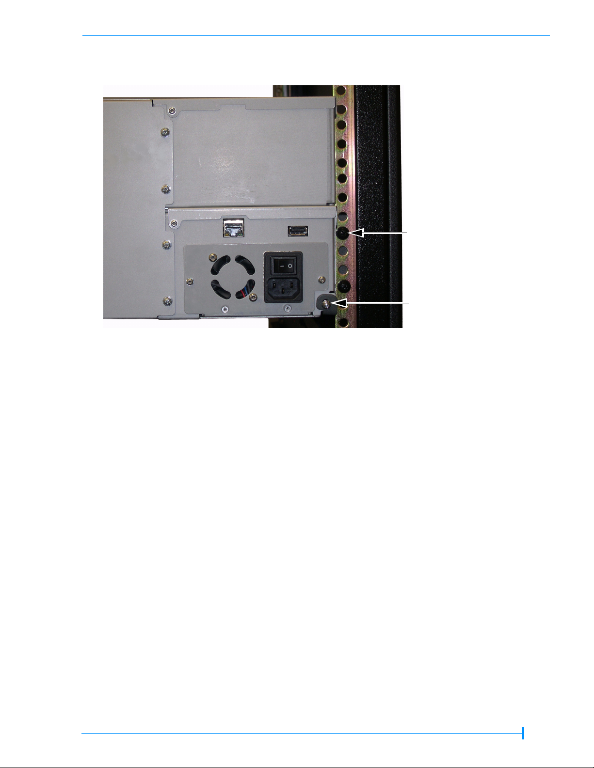
2. Remove the shipping key from the library. Carefully slide the library all the way back
until it makes contact with the small flanges at the back of the rails (see Figure 7 and
Figure 7).
3. From the back of the rack, attach the library to the rails by inserting an M3 (the two
smaller screws) screw into each of the small flanges. Tighten the screws using a #2
Phillips screwdriver.
Tandberg StorageLibrary T24—
Back of rack
M5 x 12 (black) screws
(total qty installed = 16)
(total qty shipped = 18)
Insert M3 x 8 screws here
(one on each side)
Figure 6 Attaching the Tandberg StorageLibrary T24 to the rails at the back of the rack
6 OF 8
Page 7
Tandberg StorageLibrary T48—
Back of rack
M5 x 12 (black) screws
(total qty installed = 16)
(total qty shipped = 18)
Insert M3 x 8 screws here
(one on each side)
Figure 7 Attaching the Tandberg StorageLibrary T48 to the rails at the back of the rack
ADDITIONAL INFORMATION
Library operation and use—reference the individual Product Manuals at
www.tandberg.com
Technical support—go to www.tandberg.com
For a more complete list of weight warnings (multiple languages), see the Library Safety
Notices at www.tandberg.com
7 OF 8
Page 8

NOTES
8 OF 8
 Loading...