

Page 1
TAND B ER G
Telepresence T3 RO O M I NS TA L L AT I O N G U I DE
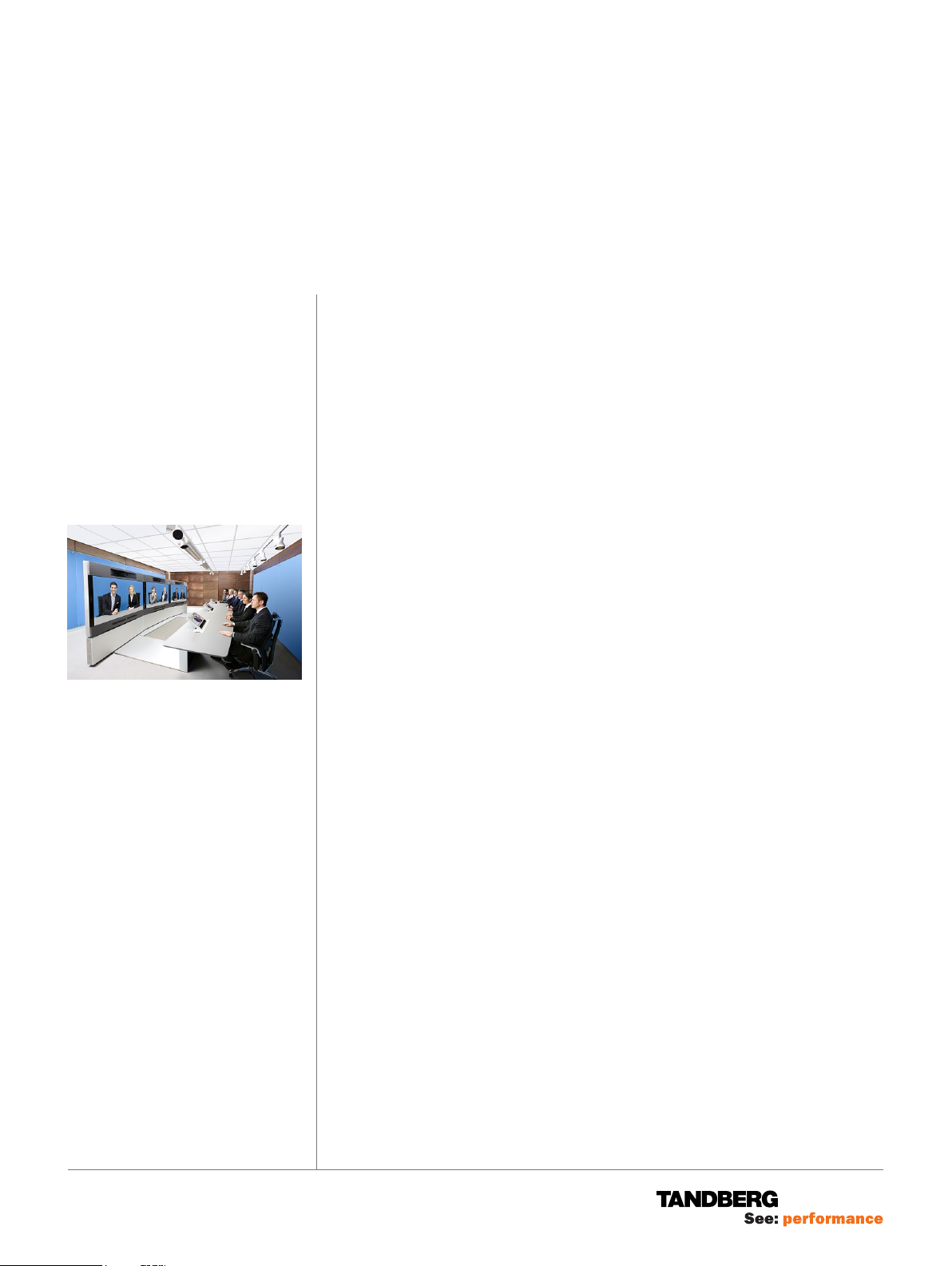
TANDBERG T3 Telepresence provides a highly immersive total Telepresence solution
designed in great detail to create an experience where meeting participants from
around the globe have the sensation that they are sitting across the table engaging
in a face to face conversation.
The orchestration of the room environment is a critical element of creating the
“illusion of being there” that is at the heart of the Telepresence experience.
TANDBERG’s immersive room package creates a total Telepresence environment
with specialized lighting, acoustics, and furnishings delivering a warm and inviting
atmosphere with superior visual and audio quality.
This document is confidential and remains proprietary
to TANDBERG Telecom AS (“TANDBERG”).
Without TANDBERG’s prior written approval, this
document, either in whole or in part, may not be
reproduced in any form or by any means, disclosed
to others outside the Client’s organisation or used for
any purpose whatsoever other than for evaluatory
purposes by the Client.
All information, descriptions, examples and
calculations contained in this document are for
guidance purposes only and should not be treated as
definitive.
Although all reasonable care has been taken to ensure
that the information contained in the presentation is
accurate and not misleading, TANDBERG shall not be
liable for any loss resulting from reliance placed on the
information contained in this document.
The following pertains to the architectural specifications required for the
implementation of Immersive and non-Immersive Telepresence T3 rooms.
These specifications are to be used as a guide for the design and implementation
of a Telepresence T3 room. Failure to follow the guidelines below will produce a
less than optimal Telepresence experience.
It should be noted that for the majority of T3 installations with the proper room
dimensions, only certain room modifications need to be made. TANDBERG and its
partners will work closely with the customer to accommodate any special requests
or modifications.
We strongly recommend that you follow the sequence outlined in this document.
TANDBERG WORLD HEADQUARTERS
Philip Pedersens vei 20
1366 Lysaker, Norway
Tel: +47 67 125 125
Fax: +47 67 125 234
Video: +47 67 126 126
E-mail: tandberg@tandberg.com
1212 Avenue of the Americas
24th Floor
New York, NY U.S.A. 10036
Tel: +1 212 692 6500
Fax: +1 212 692 6501
Video: +1 212 692 6535
E-mail: tandberg@tandberg.com
www.tandberg.com
119077.01 TELEPRESENCE T3 ROOM INSTALLATION GUIDE 12.08
PA GE 1 / 22
CO N T E NT S
Room installation guide .......................................................................................... 1
Planning and initial steps ........................................................................................ 2
Wall lattice construction ......................................................................................... 5
The baseboard ...................................................................................................... 14
The blue Walls ...................................................................................................... 15
The LED lines .......................................................................................................18
Main lighting ......................................................................................................... 19
Light mounting details .......................................................................................... 20
Page 2
TA N D B E RG
width
depth
height
RO O M I NS TA L L AT I O N G U I DE
Telepresence T3
Included in the TANDBERG Immersive
Room Package:
•Glass wall accessories T3
•Glass walls T3
•LED lights T3
•Walnut wall panels T3
•Walnut wall panel corners T3
•Walnut wall panel profiles T3
•Main lighting T3
Not included in the TANDBERG
Immersive Room Package:
•Wall lattice construction materials
•Entrance door
•Rockwool or similar insulation material
Special tools required:
•Saw for gypsum with integrated dust
extration
Suggested Workflow
Preparing your room:
• Electricity 2 days
• HVAC 3 days
• Walls w / wooden structure 1 week
• Ceiling 1 day
TANDBERG Immersive Room:
• Glass panels 1 day
• Wood panels 2–3 days
• Carpet 1 day
• Lighting 2 days
PL A N N IN G A ND IN IT I AL S T EP S
We strongly recommend that you start your planning with a meeting. Make sure
you include all the people needed:
• Project manager and assistant(s)
• Carpenters, painters, electricians, mechanical engineer
• HVAC (heating, ventilation, air conditioning) specialists
• IT personnel
• Architect
It is of vital importance that all parties agree on who is going to do what and when,
before you start the installing the system.
CHECKLIST BEFORE TANDBERG INSTALLATION
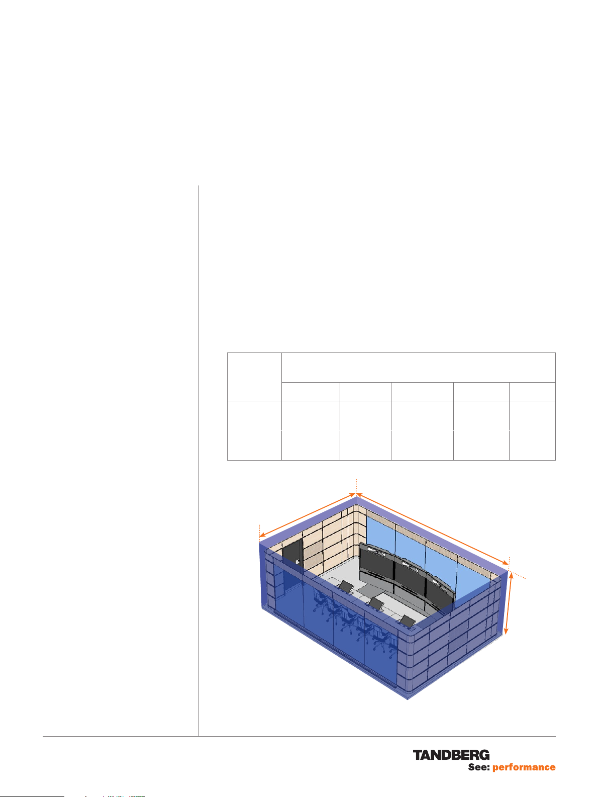
ROOM SIZE
Room Dimensions
without second row
depth width depth width height
Minimum
Optimal /
Maximum
410 cm
1
⁄2”
14’ 5
466 cm
1
⁄2”
15’ 3
675 cm
22’ 2”
720 cm
23’ 7”
Room Dimensions
with second row
438 cm
14’ 41⁄2”
508 cm
16’ 8”
675 cm
22’ 2”
720 cm
23’ 7”
211 cm
6’11”
245 cm
8’
Right: Defining the terms depth, width
and height. Note that room dimensions
refer to an empty room before T3 specific
walls and ceiling have been mounted.
Tip! More on room size can be found in the
document TANDBERG Telepresence T3
Room Requirements.
119077.01 TELEPRESENCE T3 ROOM INSTALLATION GUIDE 12.08
PA GE 2 / 22
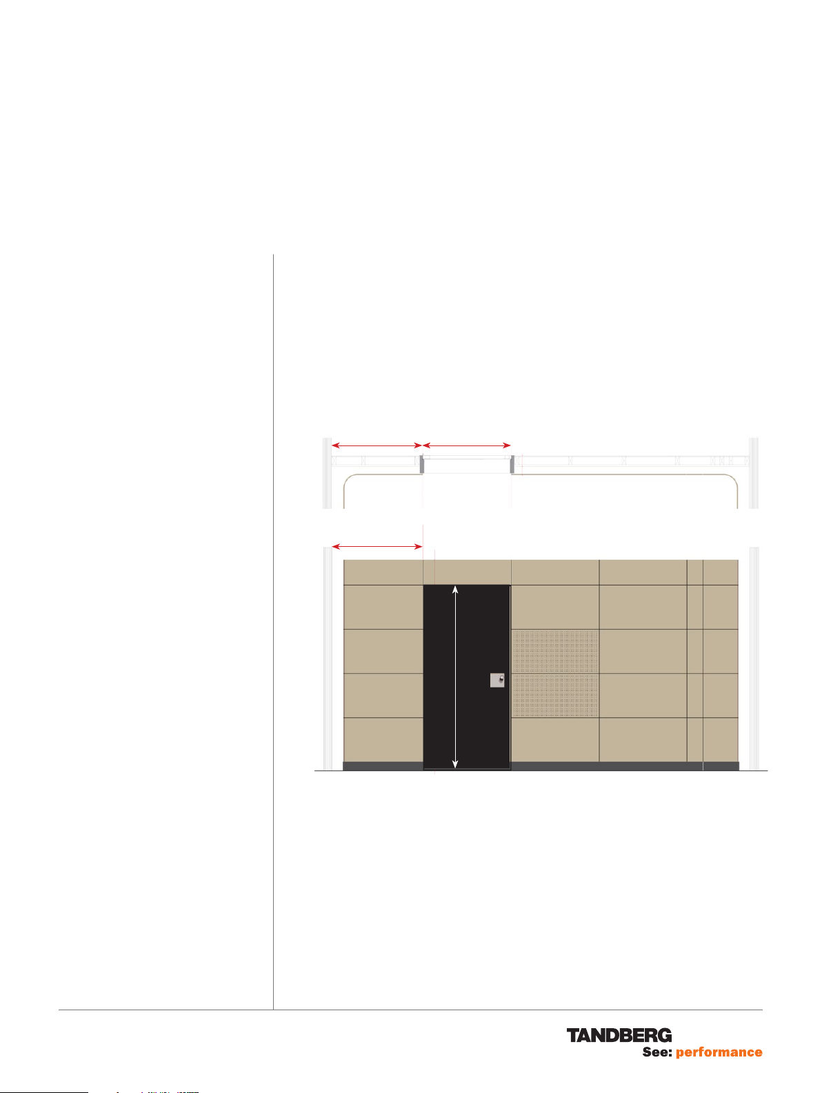
DOOR OPENING AND PLACEMENT
Page 3
TA N D B E RG
RO O M I NS TA L L AT I O N G U I DE
Telepresence T3
PL A N N IN G A ND IN IT I AL S T EP S
The door is not a part of the TANDBERG Immersive Room package. The door
opening should fit a 100 cm door. The door should open outwards.
Light opening for door: 100 cm × 208 cm
1
⁄4” 391⁄2”
40
102 cm
102 cm
100 cm
119077.01 TELEPRESENCE T3 ROOM INSTALLATION GUIDE 12.08
82”
208 cm
Door should be painted black.
The door should be mounted
flush on the outside.
PA GE 3 / 22
Page 4
TA N D B E RG
RO O M I NS TA L L AT I O N G U I DE
Telepresence T3
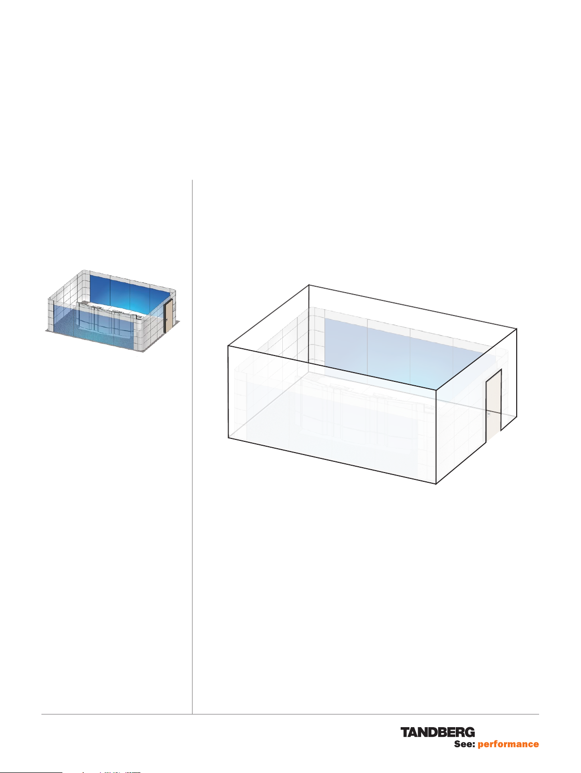
You may want to consult the document
Room Requirements for the requirements
on:
• Heating, ventilation and air-conditioning
• Electrical Outputs
• LAN Outputs
• Ceiling
The blue wall
PL A N N IN G A ND IN IT I AL S T EP S
WALL FINISH
• All 4 walls should be painted white.
• The finish should be flat and without holes, but need not be totally perfect.
• Make sure there are no cables visible behind the blue wall.
• No holes must be made higher up and no wall outlets must be mounted
higher up than 10 cm (4”) above the floor.
WHITE
WHITE
WHITE
WHITE
119077.01 TELEPRESENCE T3 ROOM INSTALLATION GUIDE 12.08
PA GE 4 / 22
Page 5
TA N D B E RG
RO O M I NS TA L L AT I O N G U I DE
Telepresence T3
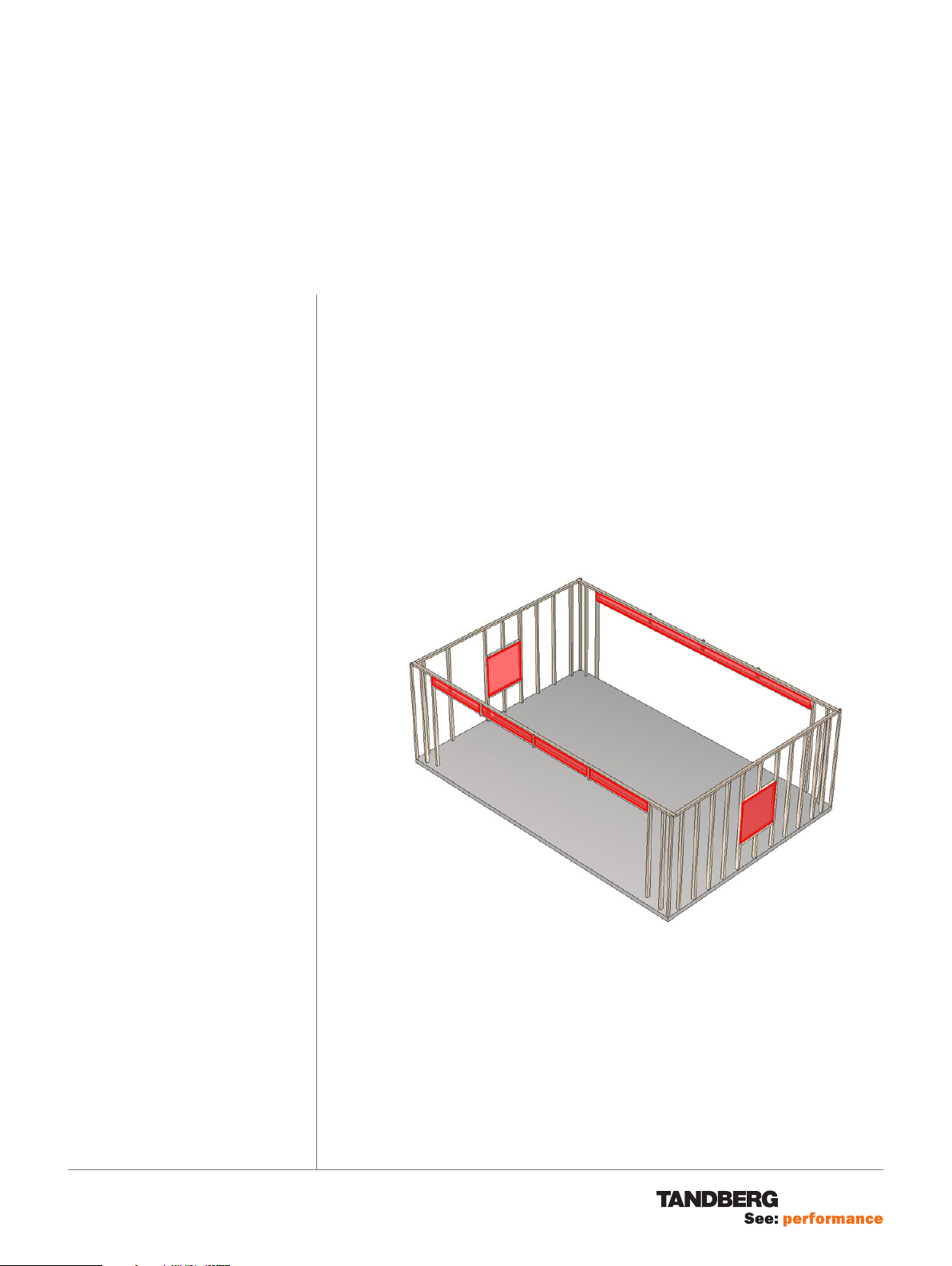
Before the panels can be mounted, you
need to set up the wall lattice construction.
Note that the materials for this and
Rockwool (or similar) insulation material
must be sourced locally.
WAL L L AT T IC E C ON S T R U C T IO N
Note! These items are not included. Suitable material should be sourced locally.
Observe the following:
• The vertical studs must not go all the way up to the ceiling. They must stop
at the highest horizontal cross member.
• The light opening for the blue glass, centered on the two long walls, is
593.5 cm × 208.5 cm / 19’5
Note that these dimensions are critical dimensions needed for perfect fitting
of the glass panels!
• The upper cross members must not let light through, i.e. there must be no
gap between the white walls and the inner surface of the cross members
(where the walnut panels shall be attached).
Note that failure to do so will cause visible stripes of light on the white walls
above the glass panels.
21
⁄32” × 6’103⁄32”.
119077.01 TELEPRESENCE T3 ROOM INSTALLATION GUIDE 12.08
PA GE 5 / 22
• The distance from the front of the wall panels/glass wall, to the inner wall
must be:
1
14 cm (5
8.5 cm (3
These distances are due to the need for sufficient space for the LED
lights behind the blue glass walls and for sufficient space for the acoustic
perforated panels on the side walls.
Build a lattice structure as shown above and on the following pages and put
Rockwool in the areas marked with red. This is where the acoustic perforated
panels are to be mounted.
⁄2”) in the front and rear
1
⁄4”) in the sides
Page 6
PA GE 7 / 22
TA N D B E RG
Telepresence T3
119077.01 TELEPRESENCE T3 ROOM INSTALLATION GUIDE 12.08
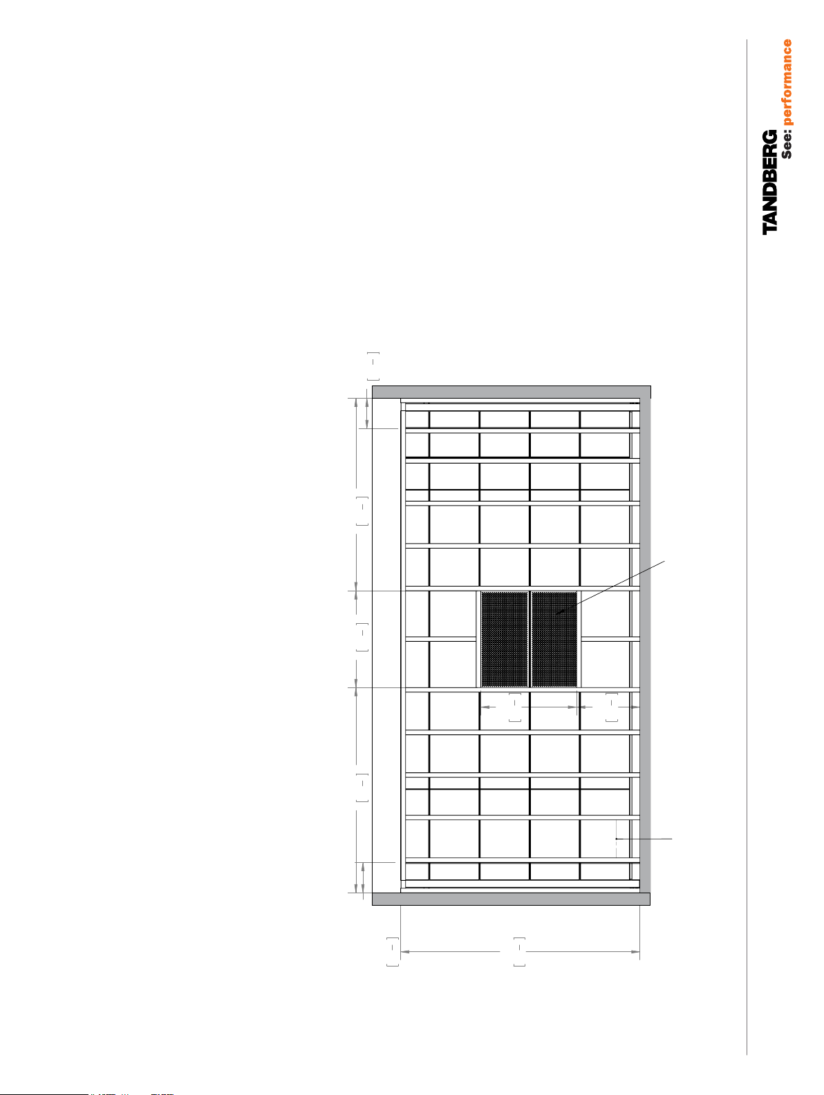
Tip! Some rooms have floors that are not
977
38
1
2
"
625
24
5
8
"
2311
91"
945
37
1
4
"
300
11
3
4
"
300
11
3
4
"
1000
39
3
8
"
1026,5
40
3
8
"
Area for insulation boards
Distance of the first
lattice from corner lattice - 300 (11,8)
entirely level. This means that the height to
the ceiling may vary about the room.
When taking measurements of the room
always use the lowermost point of the floor
as your reference plane.
This may force you to cut the baseboard
somewhat in some places, but the result
will look far better than if the baseboard fails
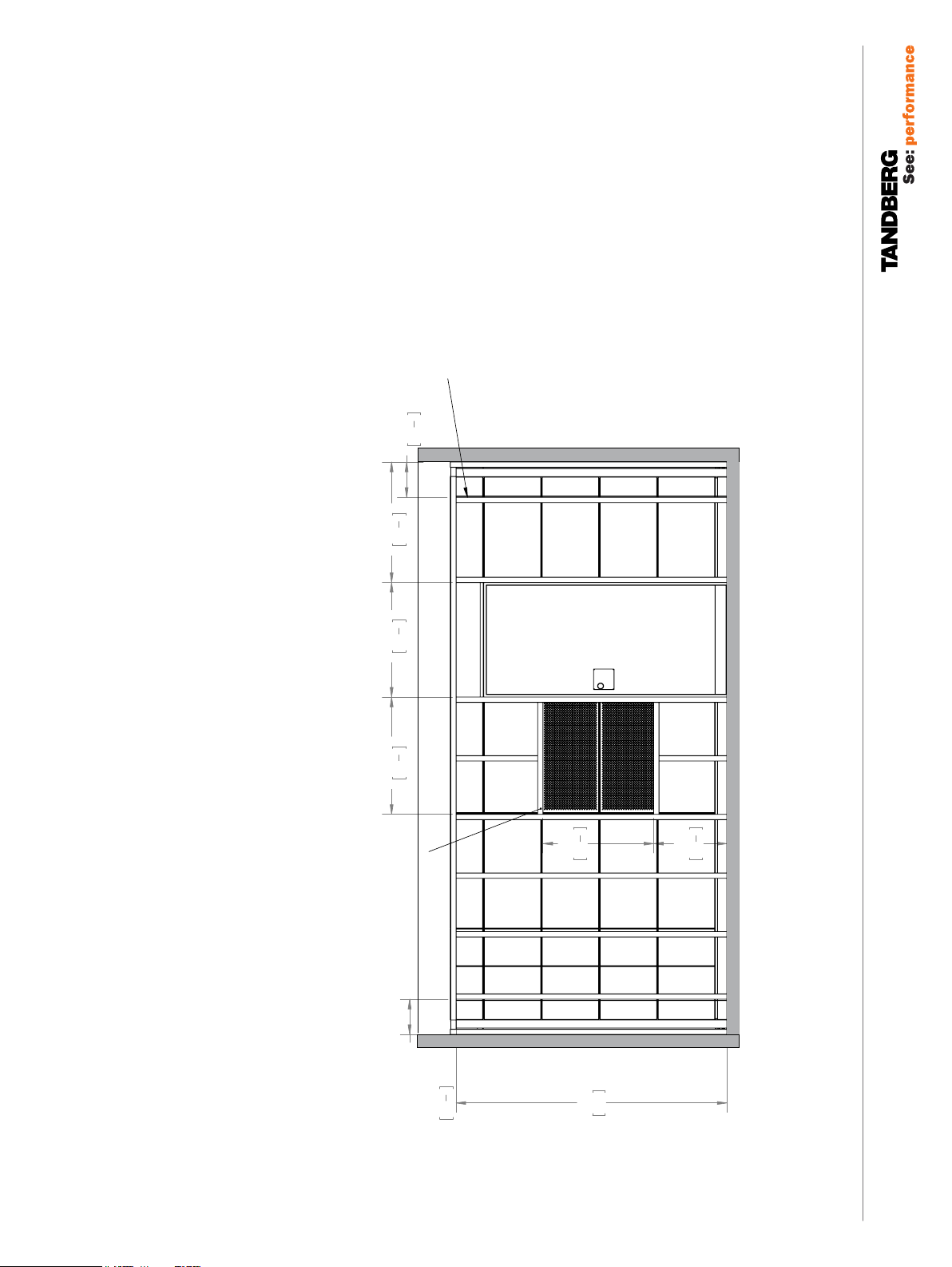
"
3
4
300
11
3
1900
5
955
"
74
"
37
4
8
to go all the way down to the floor.
945
Area for insulation boards
625
"
5
8
24
"
1
4
37
RO O M I NS TA L L AT I O N G U I DE
WAL L L AT T IC E C ON S T R U CT IO N
TA N D B E RG
Telepresence T3
3
2025
"
79
4
Gap between the
vertical lattices
300 - approx. 600mm
PA GE 6 / 22
119077.01 TELEPRESENCE T3 ROOM INSTALLATION GUIDE 12.08
"
3
4
300
11
7
2360
"
92
8
Page 7
3
300
"
3
8
40
1026,5
"
1
2
977
38
"
3
8
39
1000
Distance of the first
lattice from corner lattice - 300 (11,8)
"
4
11
TA N D B E RG
Telepresence T3
Area for insulation boards
"
3
4
300
11
945
1
"
4
37
2311
91"
625
"
5
8
24
PA GE 7 / 22
119077.01 TELEPRESENCE T3 ROOM INSTALLATION GUIDE 12.08
Page 8

TA N D B E RG
RO O M I NS TA L L AT I O N G U I DE
Telepresence T3
CA R PE T
Note! The carpet is supplied in a single roll and must be cut to measure. Roll width
is 2 m (6’6 3⁄4”). Roll out and cut the carpet as indicated below. Cut as many lengths
as required. Make sure glue is applied to the entire floor surface.
Roll out the carpet in this direction
2 m (6’6 3⁄4”)
119077.01 TELEPRESENCE T3 ROOM INSTALLATION GUIDE 12.08
PA GE 8 / 22
Page 9

TA N D B E RG
RO O M I NS TA L L AT I O N G U I DE
Telepresence T3
8×
24×
4×
8×
These elements are located in the box
marked Walnut wall panels T3.
Th E W O O D EN PANE L S
Note! These items are included in the Immersive Room Package.
What to unpack: Unpack the three boxes marked
• Walnut wall panels T3
• Walnut wall panel corners T3
• Walnut wall panel Profiles T3
Box contents:
• The box marked Walnut wall panels T3 contains aluminum baseboards
(not shown), in addition to the items shown to the upper left.
• The box marked Walnut wall panels corners T3 contains corner base-
boards (not shown), in addition shown to the lower left.
• The box marked Walnut wall panels Profiles T3 contains border lists, in
addition to the following five kinds of profiles:
2×
16×
2×
16×
These elements are located in the box
marked Walnut wall panel corners T3.
Note! It is of utmost importance that you mount the corners first.
Do as follows:
1. Start at the bottom and build your way up.
2. Fasten the profile E vertically on the lattice next to the glass walls (it will be
the border between the wooden panels and the glass walls).
3. Continue by cutting the profile B in appropriate lengths (from the edge of
the corner profile to the radius).
119077.01 TELEPRESENCE T3 ROOM INSTALLATION GUIDE 12.08
PA GE 9 / 22
Page 10

TA N D B E RG
RO O M I NS TA L L AT I O N G U I DE
Telepresence T3
Th E W O O D EN PANE L S
119077.01 TELEPRESENCE T3 ROOM INSTALLATION GUIDE 12.08
PA GE 1 0 /22
4. Insert and bend profile C in the slotted curve.
Page 11

TA N D B E RG
RO O M I NS TA L L AT I O N G U I DE
Telepresence T3
Th E W O O D EN PANE L S
5. Place the wooden panel in correct level and perpendicular position.
119077.01 TELEPRESENCE T3 ROOM INSTALLATION GUIDE 12.08
PA GE 1 1 /22
Page 12

TA N D B E RG
Back of Wood Panel upwards
Aluminum Profile
RO O M I NS TA L L AT I O N G U I DE
Telepresence T3
Integrated dust extraction
Saw for Gypsum
with guide rail
Th E W O O D EN PANE L S
6. The profiles shall fit as shown to the left.
Should you need to adjust the length of any of the panels, it is important to
use the right tools.
Note! Be sure to cut the panels with the backside up, in order to minimize
the risk of damaging the front of the panels. Observe how dimensions are
presented (page 6 of this document)
7. The profile D is to be used at the top of the topmost panel. Fasten with
screws to the top lattice.
How the profiles should fit.
The top panel with profile D as seen from
the back
119077.01 TELEPRESENCE T3 ROOM INSTALLATION GUIDE 12.08
The top panel with profile D as seen from the back is shown to the left.
8. Insert black aluminum trim pieces vertically between adjacent panels.
These are not precut and must be cut to fit from aluminum stock.
Integrated dust extraction
Saw for Gypsum
with guide rail
PA GE 1 2 /22
Page 13

TA N D B E RG
RO O M I NS TA L L AT I O N G U I DE
Telepresence T3
Th E W O O D EN PANE L S
9. The red areas in the illustration represent the perforated acoustic panels.
The panels situated above the glass walls are to be mounted with the Profile
D, both at the top and bottom of the panel.
119077.01 TELEPRESENCE T3 ROOM INSTALLATION GUIDE 12.08
PA GE 1 3 /22
Page 14

TA N D B E RG
RO O M I NS TA L L AT I O N G U I DE
Telepresence T3
Th E B AS E B O A RD
• Mount the aluminum baseboards to the lowest profile B around the whole
room. The front of the baseboards shall be aligned with the front of the
panels.
119077.01 TELEPRESENCE T3 ROOM INSTALLATION GUIDE 12.08
PA GE 1 4 /22
Page 15

TA N D B E RG
RO O M I NS TA L L AT I O N G U I DE
Telepresence T3
Tip: Wear gloves at all times when handling
the glass plates.
Caution! The glass panels should be
handled by authorized personnel only.
Caution! Glass plates should always be
stored in upright position.
Caution! The weight of the entire glass
plate should never rest on just one corner.
The blue wall behind
the participants
The blue wall
behind the screens
There are two blue walls altogether, one
behind the participants and one behind the
screens.
Th E B LU E WA L LS
Note! These items are included in the Immersive Room Package.
What to unpack: Unpack the two boxes marked
• Glass wall Accessories T3
• Glass walls T3
Box contents:
• The box marked Glass wall Accessories T3 contains the following items:
8×
8×
16×
16×
16×
6×
119077.01 TELEPRESENCE T3 ROOM INSTALLATION GUIDE 12.08
• The box marked Glass walls T3 contains the following items:
5
8 glass panels, each consisting of 9 mm (
⁄16”) glass, with the dimensions of
1964 mm × 1480 mm and with a weight of 65 kg or 142 lbs. per panel.
The glass walls are to be mounted with aluminum profiles, fastened with brackets,
joint brackets and adjusting screws and nuts. Brackets are fastened with M5 screws.
Do as follows:
1. Mount the upper profiles to the lattice.
PA GE 1 5 /22
Page 16

TA N D B E RG
RO O M I NS TA L L AT I O N G U I DE
Telepresence T3
Tip: Wear gloves at all times when handling
the glass plates.
Caution! The glass panels should be
handled by authorized personnel only.
Caution! Glass plates should always be
stored in upright position.
Caution! The weight of the entire glass
plate should never rest on just one corner.
Note! It is paramount that the distance
between the profiles is 7–8 mm (¼”)more
than the glass panel length (height when
mounted). Otherwise you will not be able
to mount the panels.
Th E B LU E WA L LS
2. Adjust so that the glass profile is flush with the vertical black side profile
(the one closest to the panels). Mount the angle bracket onto the lower
glass profile (drill a hole for the M5 screw in the glass profile). This should
fix the distance between the wall and the glass profile.
3. Measure the distance between the upper and the lower profiles. Adjust the
distance between the profiles to 1972 mm by adjusting the feet.
4. Use screws to attach the angle brackets to the wall. The glass profiles
should now be fixed.
5. Repeat 2–4 and mount the joint brackets until all are mounted.
Tip! You may want to mount the LED
lights before you mount the glass panels.
Although strictly not needed to do so, you
may find it convenient. LED mounting is
described after this section.
119077.01 TELEPRESENCE T3 ROOM INSTALLATION GUIDE 12.08
PA GE 1 6 /22
Page 17

TA N D B E RG
RO O M I NS TA L L AT I O N G U I DE
Telepresence T3
Tip: Wear gloves at all times when handling
the glass plates.
Caution! The glass panels should be
handled by authorized personnel only.
Caution! Glass plates should always be
stored in upright position.
Caution! The weight of the entire glass
plate should never rest on just one corner.
Th E B LU E WA L LS
6. Carefully unpack the glass walls. Wipe the glass clean if needed. Wear
gloves at all times to avoid leaving marks on the panels. Glass plates must
be stored in an upright position.
IMPORTANT! The weight of the glass plate should never rest on just one
corner.
Note! The glass plates should be mounted with the matte side inwards (into
the room).
7. Use the enclosed tape and mount it along the top and bottom edges of
the glass panel. There may be tape visible along the bottom edge after the
mounting. Careful alignment of the tape along the bottom edge will minimize this. You may also use a sharp knife and carefully cut and remove the
excess tape after the panels have been mounted.
8. Mount two rubber bumpers on what will be the right edge (when mounted)
of the left glass panel. Take care to position these so that they will become
covered by the profiles holding the panel in position. The rubber bumpers
serve to prevent the glass panels from touching each other.
Placing the glass walls requires a minimum of two persons. Place the glass
walls in the profiles by lifting the glass so that the top of the glass touches
the surface of the top profile. Then slowly sink the glass into the groove of
the bottom profile.
119077.01 TELEPRESENCE T3 ROOM INSTALLATION GUIDE 12.08
PA GE 1 7 /22
9. Repeat the rubber bumper mounting for the center panel. Put the second
glass in place as close to the first panel as possible.
Page 18

TA N D B E RG
140
5
1
2
"
140
5
1
2
"
4600
181
1
8
"
85
3
3
8
"
85
3
3
8
"
111
4
3
8
"
1695
66
3
4
"
885
34
7
8
"
400
15
3
4
"
885
34
7
8
"
1885
74
1
4
"
2160
85"
570
22
1
2
"
760
29
7
8
"
829
32
5
8
"
87,5
3
3
8
"
Centerline
On Floor Cable Routing
- Transport cables from T3
Power / AV / Lan
Video Lan
Customers Lan
Doc Cam Outlet
Doc Cam Capture Area
Max. size 760 x 570
Min. size 50 x 45
On floor Cable Routing
- Transport cables from T3
Doc Cam location in
suspended ceiling
4
A A A B C
A A B C
5
140
5
1
2
"
140
5
1
2
"
4600
181
1
8
"
85
3
3
8
"
85
3
3
8
"
111
4
3
8
"
1695
66
3
4
"
885
34
7
8
"
400
15
3
4
"
885
34
7
8
"
1885
74
1
4
"
2160
85"
570
22
1
2
"
760
29
7
8
"
829
32
5
8
"
87,5
3
3
8
"
Centerline
On Floor Cable Routing
- Transport cables from T3
Power / AV / Lan
Video Lan
Customers Lan
Doc Cam Outlet
Doc Cam Capture Area
Max. size 760 x 570
Min. size 50 x 45
On floor Cable Routing
- Transport cables from T3
Doc Cam location in
suspended ceiling
8
A A A A A A B C
A A A A A A B C
8
RO O M I NS TA L L AT I O N G U I DE
Telepresence T3
Th E L ED L I NE S
Note! These items are included in the Immersive Room Package.
Note! Lamps must be installed by qualified personnel only. Local regulations and
requirements may apply.
What to unpack: Unpack the box marked
• LED lights T3.
Box contents:
• This box contains the 10 × Phillips BCS722 LED light modules.
US version:
10 × eW Grace Powercore
2 × Leader Cable
8 × Jumper Cable
Kindly observe the following:
• Installation of Phillips LED lighting can begin as soon as the installation of
the blue backlighting walls is complete.
• Each blue wall contains 5 LED lights placed end to end on the floor
• 5 LED lights should be connected in series behind each blue wall.
• LED light coupling: 2 double and 1 single.
LED mounted on bracket
Hardwire outlet for LED light
Power / Lan Outlet
119077.01 TELEPRESENCE T3 ROOM INSTALLATION GUIDE 12.08
Place Center LED light on top of brackets
for glass fixture. This applies to the blue wall
behind the system only.
Leader Cable
Leader Cable
Leader Cable
LED organisation USA (Jumper cables and leader cable supplied by Tandberg
LED organisation Europe (Junction box and extra cables supplied by local electrician)
4 x jumper Cable
3 x junction box
LED 5LED 4LED 3LED 2LED 1
LED 5LED 4LED 3LED 2LED 1
PA GE 1 8 /22
Page 19

TA N D B E RG
RO O M I NS TA L L AT I O N G U I DE
Telepresence T3
MA I N LI G h T IN G
Note! These items are included in the Immersive Room Package.
What to unpack: Unpack the box marked
• Main Lighting T3
Box contents:
• The box contains 6 Fluorescent lightbulbs
US: 21W 830
EU: 39W 830
11 35W Halogen lightbulbs.
The rear ceiling lighting consists of seven 640 mm spot light armatures mechanically
fastened together and parallel wired together. (Rear edge 5 cm / 2” inner rear wall and
228 cm / 7’ 5
The front ceiling lighting consists of four 450 mm spot light armatures plus three fluorescent
light armatures mechanically fastened together and parallel wired together. (Rear edge
200 cm / 6’6
Ceiling attachment by means of hang wires provided with lighting. Anchor method in
ceiling will depend on ceiling structure and composition.
3
⁄4” from the floor. )
7
⁄10” from inner rear wall and bottom edge 228 cm / 7’ 5 3⁄4” from the floor).
119077.01 TELEPRESENCE T3 ROOM INSTALLATION GUIDE 12.08
PA GE 1 9 /22
Page 20

Press in the chrome colored end plates to cap off each
row of lights.
LI G h T M O U N TI N G DE TA I LS
RO O M I NS TA L L AT I O N G U I DE
TA N D B E RG
Telepresence T3
Thread hang wires through push fasteners. Trim off excess wire to approximately 8cm / 3”
Unscrew the light bezel. Insert light bulb. Reinstall light bezel.
Use the provided 4mm bolts ad plastic nuts to fasten
the seven lights together in one continuous row.
PA GE 2 0 /22
119077.01 TELEPRESENCE T3 ROOM INSTALLATION GUIDE 12.08
Page 21

Remove the five wire factory installed lead from the
fluorescent light armature. (This is only used with
dimming) Use a 20cm piece of the three wire lead to
couple the adjacent spot/fluorescentlights together.
There should be many extra meters of the three wire
leads from the spotlights after they are clipped to the
correct length.
Use the chrome plates to cap off the ends of the far
right and far left spotlight boxes in the two rows of
lights.
LI G h T M O U N TI N G DE TA I LS
RO O M I NS TA L L AT I O N G U I DE
TA N D B E RG
Telepresence T3
Remove screw, plastic retainer and alloy protective
guard for wiring access.
Remove screw, plastic retainer and alloy protective
guard for wiring access.
The four spotlights and the three fluorescent lights are
physically fastened together with two M4x40 screws
and knurled plastic nuts.
Blue=N
Green=GND
Brown=L
PA GE 2 1 /22
119077.01 TELEPRESENCE T3 ROOM INSTALLATION GUIDE 12.08
Page 22

TA N D B E RG
RO O M I NS TA L L AT I O N G U I DE
Telepresence T3
200 cm = 6’63⁄4”
MA I N LI G h T IN G
5 cm = 2”
Front ceiling lighting
Room
Centerline
Rear ceiling lighting
45 cm = 17
64 cm = 23
11
⁄
16
”
3
⁄
16
”
Rear
blue wall
20°
90 cm = 35
7
⁄
16
”
Adjusting the angles
10°
Above
the table
119077.01 TELEPRESENCE T3 ROOM INSTALLATION GUIDE 12.08
PA GE 2 2 /22
 Loading...