

Page 1
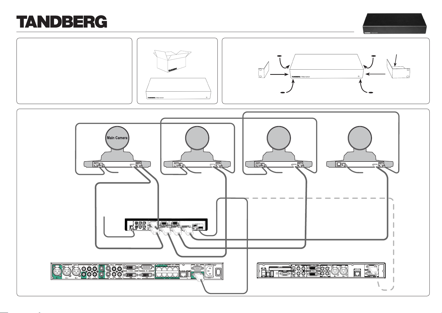
Connecting the Video Switch
Audio out
Data
Net
PC Card
1. Single 2. Single
Video out
Video in
3. Dual
2. Aux
3. Doc 4. VCR
VCR
Ethernet
PC DVI-I in
DVI-I out
1
2
4
Audio in
1
Mic.1
2
Mic.2
3
USBUSB
DC in
I
O
Camera
The Video Switch set contains:
1 Video Switch Unit
4 Rubber Feet
1 HD Camera cable (1 m) for 6000MXP Codec
1 HD Camera cable (1 m) for 3000MXP Codec
1 Power supply kit incl. cables for Video Switch
1 Power supply kit incl. cables for existing camera
1 Rack ear set (left and right)
1 Control cable (6.5 m) for Video Switch to Precision HD camera
1 HDMI cable (6.5 m) for Video Switch to precision HD camera
1 TRC4 TANDBERG Remote Control
Please report any discrepancies immediately.
Connecting up to four
TANDBERG Precision
3
HD cameras:
RJ11 – RJ45
Connect TANDBERG Video Switch
power supply here.
Connect camera power supply
here.
The Codec must be equipped with
software version F6.1 or higher to
support the use of the Video Switch.
1
Unpack the unit.
Camera 2 Camera 3 Camera 4
RJ11 – RJ45
DB 9–RJ 45
Primary chain
TANDBERG Video Switch
Mount the rack ears
and/or rubber feet
2
and mount it in the
rack, if applicable.
RJ11 – RJ45
Put the Video Switch power
supply here when rack
mounting.
Rubber feet
(rubber pads)
RJ 45 – DB 9
DVI – HDMI
TANDBERG 6000 MXP Codec
DVI – HDMI
DB 9 – RJ 45
DVI – HDMI
TANDBERG 3000 MXP Codec
116467.05Page 1 of 6
Page 2
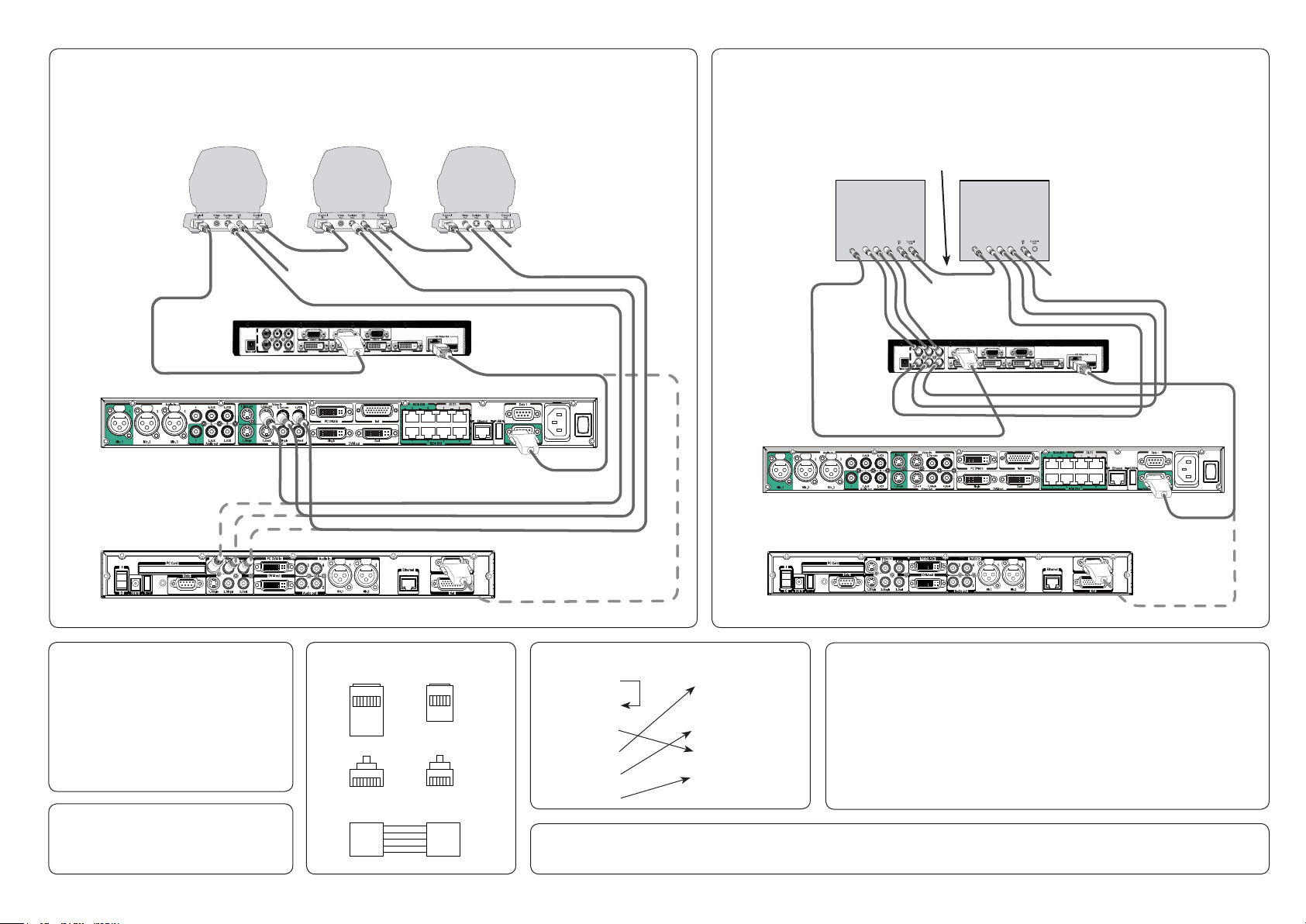
This diagram shows the additional connections needed to expand from using up to four TANDBERG
RJ45
Top
RJ45
Front
1
8
1
8
RJ11
Top
RJ11
Front
18
16
RJ45 RJ11
1
2
3
6
7
2
1
3
4
5
Audio out
Data
Net
PC Card
1. Single 2. Single
Video ou t
Video in
3. Dual
2. Aux
3. Doc 4. VCR
VCR
Ethernet
PC DVI-I in
DVI-I out
1
2
4
Audio in
1
Mic.1
2
Mic.2
3
USBUSB
DC in
I
O
Camera
Control
in
Control
in
Audio out
Data
Net
PC Card
1. Single 2. Single
Video ou t
Video in
3. Dual
2. Aux
3. Doc 4. VCR
VCR
Ethernet
PC DVI-I in
DVI-I out
1
2
4
Audio in
1
Mic.1
2
Mic.2
3
USBUSB
DC in
I
O
Camera
Precision HD cameras (see overleaf) to also include up to three TANDBERG WAVE II cameras
4
(i.e. up to seven cameras in total). Connect Video Switch power supply as shown overleaf.
Note!
Start by connecting
the Precision HD
Camera 1 Camera 2 Camera 3
cameras as shown
overleaf. The
connection shown
here comes in
addition to the one
overleaf!
RJ 11 – RJ45 RJ 11 – RJ45
RCA – RCA
RCA – RCA
S-video – S-video
Connect WAVE
camera power
supply here.
This diagram shows the connections needed to use a maximum of two analog sources
equipped with component video outputs. Connection diagram uses Sony EVI-
5
HD1 cameras as example. System supports 1280X720p50, 1280X720p59,94, and
1280X720p60 only. For full VISCA control Sony EV1-HDI cameras or true compatibles
must be used. Other units may or may not be par tly or fully controllable. Connect Video
Switch power supply as shown overleaf.
Mini DIN – Mini DIN
Connect camera power
supply here.
RCA – RCA
Camera 1 Camera 2
RCA – RCA
The Codec must be equipped with
software version F6.1 or higher to
support the use of the Video Switch.
To upgrade the software of the Precision HD
camera, connect the camera directly to the
main camera socket of the Codec (the socket
that other wise is used when connecting the
Video Switch to the Codec).
Power the units and the upgrade will start
automatically. The status will be shown on the
video system’s monitor.
RJ45–DB9 pinout is described in the
TANDBERG MXP Reference User Guide
for System Integrators, which came with
your TANDBERG Codec.
Page 2 of 6
RJ 45 – DB 9
Secondary chain
TANDBERG 3000 MXP Codec
RJ 45 – DB 9
DB 9– Mini DIN
RJ 45 – DB 9
TANDBERG 6000 MXP Codec
The Codec must be equipped with
TANDBERG 6000 MXP Codec
software version F6.1 or higher to
support the use of the Video Switch.
TANDBERG 3000 MXP Codec
TANDBERG RJ 45 – RJ 11
SONY Mini DIN Precision HD RJ 11
1 DTR 1 GND
2 DSR 2 Not Used
3 TXD 3 TXD
4 GND 4 RXD
5 RXD 5 GND
You may combine TANDBERG HD Precision cameras with analog
sources equipped with component video outputs. Just add them to the
chain of cameras in the diagram shown overleaf, but make sure the
added sources appear after the TANDBERG HD Precision cameras in
the chain (i.e. after camera 4 in the diagram overleaf).
Consequently, up to four TANDBERG HD Precision cameras may be
combined with up to two analog component video sources and up to
three TANDBERG WAVE II cameras, bringing the maximum number of
video sources (which in many cases will be all cameras) up to nine!
6 GND 6 GND
SONY Part Numbers: DB9–Mini DIN cable
SONY part number RC893
Mini DIN–Mini DIN chain cable
SONY part number RC815
116467.05
Page 3

Installation of the Video Switch
The Codec must be equipped with software version
F6.1 or higher to support the use of the Video Switch.
Basic Functionality
Physical inputs refer to explicit codec input and explicit switch input.
These can only be controlled from the command interface. xconfiguration
MainVideoSource, vidin and xconfiguration Switch Source always control
the inputs directly.
Example: To select physical input 3 on the codec, use xconfiguration
MainVideoSource: 3, as usual. To see inputs on the switch, select codec
input 1 with xconfiguration MainVideoSource: 1, and select switch input
with xconfiguration Switch Source <1..6>.
Logical inputs are used when accessing inputs from the menu, remote
control and FECC. There are five input buttons on the top of the TRC4
remote control, and these can be remapped to any switch input you
wish. The same five buttons are visible in the Presentation/Main Video
menu, and these will be remapped in the same manner. If the switch
is connected with no special configuration, selecting “main cam” in the
menu will give the current input on the switch.
Example: There are two cameras connected to the switch, which we
want to access from the menu and remote using the “main cam” and
“aux” buttons:
xconfiguration Switch LogicalInput 1 Mode: On
xconfiguration Switch LogicalInput 1 Map: 1
xconfiguration Switch LogicalInput 2 Mode: On
xconfiguration Switch LogicalInput 2 Map: 2
You can rename the inputs using the standard xconfiguration Video
Inputs Source <1..6> Name or vidname:
xconfiguration Video Inputs Source 1 Name: “HD Camera 1”
xconfiguration Video Inputs Source 2 Name: “HD Camera 2”
Note: If you select a switch input that has no mapping from the command
interface, it will be called Switch-<1..6>. If you select a codec input that
has been remapped to the switch from the command interface, it will be
called Codec-<1..5>.
to chain more cameras than 4 in the secondary chain. This will also be
possible when the switch is not connected.
xconfiguration MainVideoSource/DuoVideoSource <1..6>
Will not be changed. 1 will mean current input on the switch.
xconfiguration switch source: <1..6>
Specify which input source to use on the switch. This will only cause a
visible change if MainVideoSource is 1.
xconfiguration switch config primar y: <on/off>
Default is on. If off, the codec will only do a basic setup of the primary
chain and report what kind of cameras are connected. The codec will not
set up brightness, whitebalance, gamma etc. for each camera. Turn it off
if an external control system handles all the configuration.
xconfiguration switch config secondary: <on/off>
Default is on. If off, the codec will only do a basic setup of the secondary
chain and report what kind of cameras are connected. The codec will not
set up brightness, whitebalance, gamma etc. for each camera. Turn it off
if an external control system handles all the configuration.
xConfiguration Switch LogicalInput [1..5] Mode: <On/Off>
xConfiguration Switch LogicalInput [1..5] Map: <1..6>
Default is LogicalInput [1..5] Mode: Off.
Main cam1.
Aux2.
Doc cam3.
VCR4.
PC5.
Remaps the source buttons on top of the extended remote control.
Will also remap inputs selected from the menu, and change FECC
accordingly. If mode for a key is on, the table entry will be used to specify
which input on the switch to activate.
xcommand CameraUpgrade <1..13> <filename>
Upgrade camera or switch with new software. The software must be put
on either /tmp or /user. Camera software files are named s01692.pkg.
Switch software files are named s51200.pkg. Currently only upgrading of
the first camera/switch is supported.
New Statuses
xstatus switch
Information about software version and ID will be given by xstatus
camera 1. xstatus switch will give information about sync status for the
active input, the format, and sync status for all DVI-D inputs.
xstatus switch
*s Switch (connected=True):
Input: 1
Format: 1280X720p60
Sync: True
Sync 1: True
Sync 2: True
Sync 3: False
Sync 4: False
Active input may differ from what is given in the xconfiguration Switch
Source setting. This is because an external control system may also
change the input.
Command Interface – Configurations
Important: All camera configurations will get new ranges, 1..13 instead
of 1..4. These will behave as follows if a switch is connected:
1 will be the switch.
2..7 will be cameras connected to secondar y chain (chain originating
from Data port 2 of the switch).
8..13 will be cameras connected to the primary chain (chain originating
from Data port 1 of the switch).
Since the switch is the first entry in both chains, there is a max of 6
cameras per chain. This numbering scheme will be as compatible as
possible with existing camera support. We open up for the possibility
Command Interface – New Commands
Important: All camera commands will get new ranges, 1..13 instead of
1..4. This will work as specified in the section above.
The new commands below are also useful if there is no switch
connected.
xcommand CameraReconfigure
Reconfigures all cameras connected to the switch or codec. This may be
useful if you connect new cameras without turning the power off, since
the switch does not autodetect such changes.
116467.05Page 3 of 6
Page 4

Communicating with the Video Switch
Communicating Using VISCA
Note! This section applies only to users wanting to
control the switch directly from an external control
system connected to Data port 3 on the switch.
The following describes how to communicate
with the TANDBERG Video Switch using the
VISCA protocol. For details about the protocol
implementation, refer to the System Integrators
Guide – Interfacing to the TANDBERG Wave 2
Camera.
VISCA Interface Basics
The TANDBERG Video Switch (TVS) uses a RS-232
control interface that resembles the Sony VISCA
protocol.
TVS is configured in exactly the same way as a
VISCA camera. TVS will always be located first in
the camera chain(s).
The main jobs of the VISCA interface in the T VS are:
Select which video source to use•
Route VISCA messages to the connected •
cameras
Control picture resolutions sent to the codec•
Cameras chained to the switch will start with id 2.
The codec will automatically recognize this and map
the cameras accordingly.
VISCA Serial Ports
The switch has a total of 4 serial ports that
communicate using the VISCA protocol.
Port 0, on the THSI interface, is always •
connected to the codec.
Port 1 is the primary VISCA chain for cameras •
connected to the Switch.
Port 2 is the secondary VISCA chain for the •
cameras that normally are connected to codec
video inputs 2-5. See the section on Enhanced
VISCA below.
Port 3 is intended for external control systems, •
and works in the same way as port 0, but with
some limitations on available commands. It
is comparable to running the daisy port on a
TANDBERG Precision HD Camera in dualvisca
mode.
This article covers the use of port 3 as the control
port for the switch. You may use port 0 if you do
not intend to use the THSI interface, but only use
HDMI out.
Enhanced VISCA
Since the switch has two possible camera chains,
all normally formatted commands will be sent to
the primary chain. To access the secondary chain,
you must first turn Enhanced VISCA on with the
SW_eVisca command.
Commands going to the secondary chain must be
prefixed with FE 01. Replies from the secondary
chain will also be prefixed with FE 01. You will only
receive push messages from the secondary chain if
Enhanced VISCA is turned on.
Important: Since the switch can receive VISCA from
either the codec or an external control system, and
since there are two possible camera chains, there
are limitations on how commands are issued and
answered:
Only one command can be processed at a time•
Sending a new command when you receive an •
ACK from a Sony camera is not allowed. ACK
messages will be thrown away by the switch
Reply will always go to the source that issued the •
command.
Sony push messages will be sent to both •
sources.
If this is not expected behaviour, an external control
system may, of course, be setw to control all
connected cameras directly via VISCA.
VISCA Messages
Commands that are prefixed with SW_ are new for
the switch. The CAM_ prefix is used for commands
that are copied from TANDBERG Precision HD
Camera, or are standard VISCA messages.
VISCA Standard Commands
Command Set Command Packet Comments
CAM_IF_Clear 8x 01 00 01 ff Clear command buffer. Stop any current
operation in progress.
CAM_ Address_Set 8x 30 0p ff p = address for this device. If x=8
(broadcast), increase p with 1 before
sending to chain.
CAM_Command_Cancel 8x 2p ff p = Socket ID. Not supported in TVS
CAM_Power 8x 01 04 00 0p ff p = 2: Power on. p = 3: Power off.
VISCA Standard Inquiries
Command Command Packet Comments
IF_DeviceType_Inq 8x 09 00 02 ff y0 50 gg gg hh hh jj jj kk f f
gggg = Vendor ID
hhhh = Model ID
jjjj = ROM Revision
kk = Max sockets
(No support for this in the TANDBERG
Video Switch. Ignore it.)
CAM_Power_Inq 8x 09 04 00 ff y0 50 0p f f
p = 2: Power on.
p = 3: Power off.
VISCA Standard Push Messages
Command Command Packet Comments
CAM_Network_Change x0 38 ff This indicates that cameras have been
added to or removed from the camera
chain.
To avoid issues with (some) Sony
cameras, the control system or
codec should delay 9 seconds before
reconfiguring the chain.
116467.05Page 4 of 6
Page 5

Configuration Commands
Messages starting with 8x-01-40-<00..1f> are configuration commands.
Inquiries
Messages starting with 8x- 09...
Command Command Packet Comments
SW_Port_0_Cfg 8x 01 40 00 ... ff Currently not in use.
SW_Port_1_Cfg 8x 01 40 01 ... ff Currently not in use.
SW_Port_2_Cfg 8x 01 40 02 0p ff p=0: Disable this port
p=1: Enable this port as a secondary
VISCA chain port for cameras usually
connected to codec input 2-5 (default).
p=2: Use this port as a debug port.
SW_Port_3_Cfg 8x 01 40 03 0p ff p=0: Disable this port
p=1: Enable this port as a dual visca port
(default).
p=2: Use this port as a debug port.
SW_Port_x_Push_Cfg 8x 01 40 04 0p 0q 0r ff Configure which push messages to send
for given por t.
p=0/3: Configure port 0 or 3.
qr bit 0: Enable/disable SW_Input_Push.
qr bit 1: Enable/disable SW_Sync_Push.
qr bit 2: Enable/disable Enhanced VISCA.
qr = 00 is default for both ports.
Switch control commands
Messages starting with 8x-01-40-<20..3f> are switch control commands.
Command Set Command Packet Comments
SW_Input_Set 8x 01 40 20 0p ff Sets which input to use.
p=0..5
This will generate a SW_Input_Push on
the THSI Visca por t if issued from the
dual visca port and vice versa.
Command set Command Packet Reply and comments
CAM_ID_Inq 8x 09 04 22 FF Reply: 90 50 zz xx 00 yy FF
zz xx = switch rev, zz=0x40 for TVS
yy = firmware rev
CAM_SWID_Inq 8x 09 04 23 ff Reply: x0 50 [1-125 bytes SWID] ff.
SW_Input_Inq 8x 09 40 20 ff Reply 90 50 0p ff
p=Active input, 0..5
SW_Sync_Inq 8x 09 40 e0 0p ff Input: p=Input 0..5
Reply: 90 50 0p ff
p=2: Input has sync
p=3: No sync on input
SW_InputFormat_ Inq 8x 09 40 e1 ff Reply: 90 50 0p 0q f f
pq = Format for active input.
0 = 720p60
1 = 720p59.94
2 = 720p50
Push Messages
Command set Push Message Comments
SW_Input_Push x0 01 40 20 0p ff The input has been changed.
p = the new input source
SW_Sync_Push x0 01 40 e0 0p 0q ff Sync state has changed on an input.
This one will also be sent if the format is
changed, so if sync is on, send a SW_
Format_Inq.
p = source 0..5
q = state: 2 = sync, 3 = no sync
Misc.
Command Command Packet Comments
CAM_Boot 8x 01 42 ff Reboot the switch. This will also reset
serial speed to 9600.
www.tandberg.com
116467.05Page 5 of 6
Page 6

A 㑻ໄᯢ( A Class product declaration)
ᴀѻકЎ A 㑻 ITEˈ݊Փ⫼䇈ᯢ,䫁⠠ㄝᰒ㨫ԡ㕂ЁᏆࣙབϟݙ
ᆍⱘໄᯢ(We declare here that the subject product is A Class ITE
product, and the following statement is clearly marked in the user
manual and nameplate ˖
ໄ ᯢ
ℸЎ A 㑻ѻકˈ ⫳⌏ ⦃๗Ёˈ䆹ѻક ৃ㛑Ӯ䗴៤᮴㒓 ⬉ᑆᡄ DŽ䖭
⾡ᚙމϟˈ ৃ㛑䳔 㽕⫼᠋ᇍ݊ᑆᡄ 䞛পߛ ᅲৃ㸠ⱘᮑDŽ
WARNING:
This is a class A product. In a domestic environment this product may
cause radio interference in which case the user may be required to take
adequate measures.
ໄ
ᯢ᠔ԡ㕂 Position of the Declaration˖
݀ৌ Company Name˖
TANDBERG Telecom AS
ㅒᄫ/Ⲫゴ Signature/ Stamp˖
Disclaimer
The information in this d ocument is fur nished for informational pur poses only, is subject to
change withou t prior notice, and should not be constr ued as a commitm ent by TANDBERG.
TANDBERG reser ves th e right to amend any of the information given in this document in
order to t ake account of new developments.
Every effor t has been mad e to supply complete and accurate information, however, TANDBERG assumes no responsibilit y or liability for any errors or inaccuracies that may appear
in this document, nor for any infringements of patents or other rights of t hird parties resulting from its use. No license is granted under any patents or p atent rights of TANDBERG.
For your p rotec tion please read these safet y instr uctions completely before you con nect the equipment to the power source. Carefully observe all warnings, pre cautions and
instructions both on the apparatus and in these operating instructio ns.
Retain this manual for future reference.
Water and Moisture
Do not operate the apparatus under or near water – for •
example near a bathtub, kitchen sink, or laundry tub, in a wet
basement, near a swimming pool or in other areas with high
humidity.
Do not touch the product with wet hands.•
Cleaning
Unplug the apparatus from communication lines, mains •
power-outlet or any power source before cleaning or
polishing. Do not use liquid cleaners or aerosol cleaners. Use
a lint-free cloth lightly moistened with water for cleaning the
exterior of the apparatus.
Unplug the apparatus from communication lines before •
cleaning or polishing. Do not use liquid cleaners or aerosol
cleaners. Use a lint-free cloth lightly moistened with water for
cleaning the exterior of the apparatus.
Ventilation
Do not block any of the ventilation openings of the apparatus. •
Never cover the slots and openings with a cloth or other
material. Never install the apparatus near heat sources
such as radiators, heat registers, stoves, or other apparatus
(including amplifiers) that produce heat.
Do not place the product in direct sunlight or close to a •
surface directly heated by the sun.
Lightning
Never use this apparatus, or connect/disconnect communication
cables or power cables during lightning storms.
Dust
Do not operate the apparatus in areas with high concentration of
dust.
Vibration
Do not operate the apparatus in areas with vibration or place it
on an unstable sur face.
attempt to connect mains power, or any other power source,
before consulting service personnel.
The plug connecting the power cord to the product power •
supply ser ves as the main disconnect device for this
equipment. The power cord must always be easily accessible.
Route the power cord so as to avoid it being walked on or •
pinched by items placed upon or against it. Pay particular
attention to the plugs, receptacles and the point where the
cord exits from the apparatus.
Do not tug the power cord.•
If the provided plug does not fit into your outlet, consult an •
electrician.
Never install cables, or any peripherals, without first •
unplugging the device from it’s power source.
Always use the power supply (AC–DC adapter) provided with •
this product.
Replace only with power supply (AC–DC adapter) specified •
by TANDBERG.
Never connect the attached power supply (AC –DC adapter) to •
other products.
Servicing
Do not attempt to service the apparatus yourself as opening •
or removing covers may expose you to dangerous voltages or
other hazards, and will void the warranty. Refer all servicing to
qualified service personnel.
Unplug the apparatus from its power source and refer •
servicing to qualified personnel under the following conditions:
If the power cord or plug is damaged or frayed. •
If liquid has been spilled into the apparatus.•
If objects have fallen into the apparatus. •
If the apparatus has been exposed to rain or moisture •
If the apparatus has been subjected to excessive shock by •
being dropped.
If the cabinet has been damaged.•
If the apparatus seems to be overheated. •
If the apparatus emits smoke or abnormal odor.•
If the apparatus fails to operate in accordance with the •
operating instructions.
Power Connection and Hazardous Voltage
The product may have hazardous voltage inside. Never •
attempt to open this product, or any peripherals connected to
the product, where this action requires a tool.
This product should always be powered from an earthed •
power outlet.
Never connect attached power supply cord to other products.•
In case any par ts of the product has visual damage never •
Accessories
Use only accessories specified by the manufacturer, or sold with
the apparatus.
Communication Lines
Do not use communication equipment to repor t a gas leak in the
vicinit y of the leak.
116467.05Page 6 of 6
 Loading...