

Page 1

Management Server
Quick Setup Guide
D13939 Rev 04
This document is not to be reproduced in whole or in part without permission in writing from:
Page 2

TANDBERG Management Server Quick Setup Guide
Trademarks and Copyright
All rights reserved. This document contains information that is proprietary to TANDBERG. No part
of this publication may be reproduced, stored in a retrieval system, or transmitted, in any form, or
by any means, electronically, mechanically, by photocopying, or otherwise, without the prior
written permission of TANDBERG. Nationally and internationally recognized trademarks and
trade names are the property of their respective holders and are hereby acknowledged.
Contains iType™ from Agfa Monotype Corporation.
Disclaimer
The information in this document is furnished for informational purposes only, is subject to
change without prior notice, and should not be construed as a commitment by TANDBERG. The
information in this document is believed to be accurate and reliable; however TANDBERG
assumes no responsibility or liability for any errors or inaccuracies that may appear in this
document, nor for any infringements of patents or other rights of third parties resulting from its
use. No license is granted under any patents or patent rights of TANDBERG.
This document was written by the Research and Development Department of TANDBERG,
Norway. We are committed to maintain a high level of quality in all our documentation. Towards
this effort, we welcome you to Contact us
and structure of this document.
Copyright © 2007 TANDBERG. All rights reserved. TANDBERG is a registered trademar k of
TANDBERG ASA and/or its subsidiaries in the United States and/or other countries.
COPYRIGHT © 2007, TANDBERG
with comments and suggestions regarding the content
ii
Page 3

Environmental Issues
Quick Setup Guide
Thank you for buying a product, which contributes to a reduction in pollution, and thereby helps
save the environment. Our products reduce the need for travel and transport and thereby reduce
pollution. Our products have either none or few consumable parts (chemicals, toner, gas, paper)
and low energy consuming products.
Waste handling
There is no need to send any products or material back to TANDBERG as there are no
consumables to take care of. Please contact your local dealer for information on local waste
handling and recycling of electronic products.
Production of products
Our factories employ the most efficient environmental methods for reducing waste and pollution
and ensuring the products are recyclable.
Digital User Manuals
TANDBERG is pleased to announce that it has replaced the printed versions of its User Manuals
with a digital CD version. The environmental benefits of this are significant. The CDs are
recyclable and the savings on paper are huge. A simple web-based search featur e helps users
directly access the information they need. If desired, the user manuals on the CD can still be
printed locally.
iii
Page 4

TANDBERG Management Server Quick Setup Guide
Operator Safety Summary
For your protection, please read these safety instructions completely before operating the
equipment and keep this manual for future reference. The information in this summary is intended
for operators. Carefully observe all warnings, precautions and instructions both on the apparatus
and in the operating instructions.
Equipment Markings
The lightning flash symbol within an
equilateral triangle is intended to alert the
user to the presence of uninsulated
“dangerous voltages” within the product’s
enclosure that may be of sufficient
magnitude to constitute a risk of electrical
shock.
The exclamation mark within an equilateral
triangle is intended to alert the user to the
presence of important operating and
maintenance (servicing) instructions
accompanying the equipment.
Warnings
Water and moisture - Do not operate the equipment under or near water - for example
near a bathtub, kitchen sink, or laundry tub, in a wet basement, or near a swimming pool
or in areas with high humidity.
Cleaning - Unplug the apparatus from the wall outlet before cleaning or polishing. Do not
use liquid cleaners or aerosol cleaners. Use a lint-free cloth lightly moistened with water
for cleaning the exterior of the apparatus.
Ventilation - Do not block any of the ventilation openings of the apparatus. Install in
accordance with the installation instructions. Never cover the slots and openings with a
cloth or other material. Never install the apparatus near heat sources such as radiators,
heat registers, stoves, or other apparatus (including amplifiers) that produce h eat.
Grounding or Polarization - Do not defeat the safety purpose of the polarized or
grounding-type plug. A polarized plug has two blades with one wider than the other. A
grounding type plug has two blades and a third grounding prong. The wide blade or third
prong is provided for your safety. If the provided plug does not fit into your outlet, consult
an electrician.
Power-Cord Protection - Route the power cord so as to avoid it being walked on or
pinched by items placed upon or against it, paying particular attention to the plugs,
receptacles, and the point where the cord exits from the apparatus.
Attachments - Only use attachments as recommended by the manufacturer.
Accessories - Most systems should only be used with a cart, stand, tripod, bracket, or
table specified by the manufacturer, or sold with the apparatus. When a cart is used, use
caution when moving the cart/apparatus combination to avoid injury from tip-over.
Lightning - Unplug this apparatus during lightning storms or when unused for long periods
of time.
iv
Page 5

Quick Setup Guide
Servicing - Do not attempt to service the apparatus yourself as opening or removing
covers may expose you to dangerous voltages or other hazards, and will void the
warranty. Refer all servicing to qualified service personnel.
Damaged Equipment - Unplug the apparatus from the outlet and refer servicing to
qualified personnel under the following conditions:
When the power cord or plug is damaged or frayed
If liquid has been spilled or objects have fallen into the apparatus
If the apparatus has been exposed to rain or moisture
If the apparatus has been subjected to excessive shock by being dropped, or the
cabinet has been damaged
If the apparatus fails to operate in accordance with the operating instructions
v
Page 6

TANDBERG Management Server Quick Setup Guide
Contact us
If you have any questions, comments or suggestions, please see the
www.tandberg.com
It is also possible to send a fax or mail to the attention of:
Product and Sales Support
TANDBERG
P.O. Box 92
1325 Lysaker
Norway
Tel: +47 67 125 125
Fax: +47 67 125 234
Online Support service at
vi
Page 7

Quick Setup Guide
End-User License Information
IMPORTANT: THE USER MANUAL CD FOR THIS PRODUCT CONTAINS IMPORTANT
TERMS AND CONDITIONS INCLUDING END USER LICENSE AGREEMENTS. THE LICENSE
AGREEMENTS SHOULD BE READ PRIOR TO USE. USE OF THIS PRODUCT CONSTITUTES
ACCEPTANCE OF THE TERMS OF THE LICENSES.
vii
Page 8

TANDBERG Management Server Quick Setup Guide
Table of Contents
1 Introduction......................................................................................................................... 9
2 Installation......................................................................................................................... 10
2.1 Unpacking................................................................................................................... 11
2.2 Connecting cables...................................................................................................... 12
2.3 IP Address Setting Configuration...............................................................................13
2.3.1 IP setting configuration:........................................................................... 13
3 Product Registration and Updates ................................................................................... 15
3.1 Security Updates........................................................................................................15
4 General Use...................................................................................................................... 16
4.1 Restart and shutdown................................................................................................. 16
4.1.1 How to restart the Management Server.................................................. 16
4.1.2 How to shutdown the Management Server.............................................17
4.2 Client Software Requirements.................................................................................... 17
5 Administrator Settings ...................................................................................................... 19
5.1 Operating System Settings.........................................................................................19
5.2 TANDBERG Management Suite Settings................................................................. 20
5.3 Added systems........................................................................................................... 22
viii
Page 9

1 Introduction
Quick Setup Guide
The TANDBERG Management Server is a server that comes with the TANDBERG Management Suite
(TMS) pre-installed.
This guide will take you through the initial steps of setting up the TANDBERG Management Server before
first time use.
Please refer to the Getting Started section of the TANDBERG Management Suite Installation Manual –
Getting Started as well as the TANDBERG Management Suite Administrator’s Guide for further
information on how to configure TMS.
Introduction 9
Page 10

TANDBERG Management Server Quick Setup Guide
2 Installation
Precautions:
Never install communication wiring during a lightning storm.
Never install jacks for communication cables in wet locations unless the jack is specifically
designed for wet locations.
Never touch uninstalled communication wires or terminals unle ss the communication line has
been disconnected at the network interface.
Use caution when installing or modifying communication lines.
Avoid using communication equipment (other than a cordless type) during an electrical storm.
There may be a remote risk of electrical shock from lightning.
Do not use the communication equipment to report a gas leak in the vicinity of the leak.
Always connect the product to an earthed socket outlet.
The socket outlet shall be installed near to the equipment and shall be easily accessible.
Never install cables without first switching the power OFF.
This product complies with the following directives:
LVD 73/23/EC, EMC 89/366/EEC, R&TTE 99/5/EEC,
Directive 73/23/EEC (Low Voltage Directive)
Standard EN 60950-1
Directive 89/336/EEC (EMC Directive)
Standard EN 55022, Class A
Standard EN 55024
Standard EN 61000-3-2/-3-3
Approved according to UL 60950-1 and CAN/CSA C22.2 No. 60950-1-03
Complies with FCC15B Class A
10
Page 11

2.1 Unpacking
Quick Setup Guide
To avoid damage to the unit during transportation, the Management Server is delivered in a special
shipping box, which should contain the following components:
User Manual and other documentation on CD.
Rack-ears, screws and screwdriver.
Cables:
o Power cable
o Ethernet cable
TANDBERG Management Server
Installation site preparations
Make sure that the Management Server is accessible and that all cables can be easily connected.
For ventilation: Leave a space of at least 10cm (4 inches) behind the Management Server’s rear
panel and 10cm (4 inches) in front of the front panel.
The room in which you install the Management Server should have an ambient temperature
between 0
humidity.
Do not place heavy objects directly on top of the Management Server.
Do not place hot objects directly on top, or directly beneath the Management Server.
Use a grounded AC power outlet for the Management Server.
Rack Mounting (optional)
The Management Server comes with rubber feet for standalone installation and brackets for mounting in
standard 19” racks.
º
C and 35ºC (32ºF and 95ºF) and between 10% and 90% non-condensing relative
Before starting the rack mounting please make sure the TANDBERG Management Server is placed
securely on a hard flat surface.
1. Disconnect the AC power cable.
2. Make sure that the mounting space is prepared according to the ‘Installation site preparations’
above.
3. Attach the brackets to the Management Server on both sides of the unit.
4. Insert the Management Server into a 19” rack, and secure with screws in the front (four screws).
Introduction 11
Page 12

TANDBERG Management Server Quick Setup Guide
2.2 Connecting cables
LAN cable
Connect a LAN cable from the ‘LAN 1’ connector on the Management Server to your network. The LAN 2,
3 and 4’ connectors are not used and should be left open.
Power cable
Connect the system power cable to an electrical distribution socket. Press the power switch button at the
back side to ‘1’ to turn on the Management Server. On the front panel of the system the power indicator
LED, marked ‘Pwr’, will light up.
12
Page 13

Quick Setup Guide
2.3 IP Address Setting Configuration
The Management Server requires the IP Address Settings to be configured before it can be used. IP
Address Configuration can be made using the LCD Panel.
Front view of the Management Server with the LCD panel:
LCD Panel buttons and their functions:
Up and Down
arrows
Enter
Return
Used to select items in the menu, move between values in a
numerical address and modify numerical values.
Used to enter the edit mode and confirm selection or entry.
Used to return to the previous menu screen or exit the edit
mode without saving the latest entry.
2.3.1 IP setting configuration:
The LCD panel allows you to set the IP address configuration.
1. Press Enter to display the Main Menu screen.
2. From the Main Menu screen, use the Up or Down arrow to select IP Settings.
3. Press Enter to confirm your selection.
4. From the IP Settings menu, use the Up or Down arrow to select IP Address and press Enter twice to
start the edit mode.
Introduction 13
Page 14

TANDBERG Management Server Quick Setup Guide
5. Move between characters by using the Up and Down arrows. Edit values by pressing Enter and usi ng
the Up or Down arrow to modify. Press Enter again to confirm the value, or press Return to restore
the value to its previous state.
6. When finished editing the address, press Return. You will be asked to confirm your address entry on
the following screen. At the Save Changes? Prompt, use the Up or Down arrow to select Yes and
press Enter to confirm.
7. Press Return to go back to the IP Settings menu.
8. Use the Up or Down arrow to select Subnet Mask and press Enter twice.
9. Repeat steps 5-6 to enter the Subnet Mask address.
10. Press Return to go back to the IP Settings menu.
11. Use the Up or Down arrow to select Default Gateway and press Enter twice.
12. Repeat steps 5-6 to enter the Default Gate way address.
14
Page 15

Quick Setup Guide
3 Product Registration and Updates
You need to register the product if you would like to receive an email from TANDBERG Constant Care
Services when Management Server updates to the TANDBERG Management Server become available.
You can also check the following ftp site for all available downloads:
http://ftp.tandberg.net/pub/software/tms/
3.1 Security Updates
All relevant security updates for the TANDBERG Management Server are available from the following ftp
site: http://ftp.tandberg.net/pub/software/tms/security_updates/.
IT IS IMPORTANT THAT YOU DOWNLOAD AND INSTALL ALL SECURITY UPDATES FROM THE
TANDBERG FTP SITE BEFORE USING THIS PRODUCT. YOU SHOULD ALSO CHECK THIS SITE
REGULARLY TO SEE IF NEW SECURITY UPDATES ARE AVAILABLE.
Installation of security updates and software upgrades on the Management Server should always
be done using the local default administrator account.
Introduction 15
Page 16

TANDBERG Management Server Quick Setup Guide
4 General Use
TANDBERG Management Server
The Management Server should always be turned on.
The unit itself should not be available to users at any time.
If the system does not respond:
Check the LCD panel to determine if the unit is switched on and ‘live’.
Make sure that the Management Server is switched on by using the On/Off switch located at the
rear of the unit.
Restart the Management Server using the LCD panel. For details, see section 3.1, Restart an d
shutdown.
4.1 Restart and shutdown
The server can be restarted and shutdown via the LCD panel.
4.1.1 How to restart the Management Server
1. Press Enter to display the Main Menu screen.
2. From the Main Menu screen, use the Up or Down arrow to select Commands.
3. Press Enter to confirm your selection.
4. From the Commands menu, use the Up or Down arrow to select Restart and press Enter.
5. You will be asked to confirm this action on the following screen. At the Restart? prompt, use the Up or
Down arrow to select Yes and press Enter to confirm.
16
Page 17

Quick Setup Guide
4.1.2 How to shutdown the Management Server
1. Press Enter to display the Main Menu screen.
2. From the Main Menu screen, use the Up or Down arrow to select Commands.
3. Press Enter to confirm your selection.
4. From the Commands menu, use the Up or Down arrow to select Shutdown and press Enter.
5. You will be asked to confirm this action on the following screen. At the Shutdown? prompt, use the
Up or Down arrow to select Yes and press Enter to confirm.
NOTE:
Please note that there is currently no indication on the LCD panel to tell the
administrator that the machine has shut down and that it is safe to turn off the
server.
Typically server is in a state that it is safe to shutdown within a few minutes.
4.2 Client Software Requirements
Minimum requirements:
• Microsoft Internet Explorer 5.5 or newer
• Mozilla Firefox 1.5 or newer
• Java Virtual Machine Runtime Engine (JRE) 1.5.0
Recommended requirements:
• Microsoft Internet Explorer 6.0 or newer
• Mozilla Firefox 1.5. or newer
• Java Virtual Machine Runtime Engine (JRE) 1.5.0
Java Virtual Machine Runtime Engine is required for using the Monitoring pages in TMS. The JRE will
automatically be downloaded and installed from the Internet if it is not found on the client. If the client does
not have Internet access, the JRE can be downloaded directly from the TMS server. The path is found in
the Monitoring section in the TMS help texts (click the question mark in the upper right corner of the
screen in any TMS page).
Windows versions prior to Windows NT 4.0 Service Pack 4 are not recommended on client wo rkstations.
Note that if you are using Windows NT 4.0 SP4 or Windows 2000 client workstations, authentication may
fail as the default setting for LAN Manager Authentication Level is ‘Send LM & NTLM responses’. This
should be set to 'Send LM & NTLM – use NTLMv2 session security if negotiated'. You find the LAN
Manager Authentication Level setting in Local Policies > Security Option in Control Panel > Administrative
Tools > Local Security Policy.
Introduction 17
Page 18

Page 19
5 Administrator Settings
Before the TANDBERG Management Server can be taken into use, some basic settings need to
be configured.
5.1 Operating System Settings
You can access the Web User Interface for Microsoft Windows Server administration to configure
operating system settings.
1. Start a web browser and enter the address
https://<ManagementServerIPAddress>:8098, where <Manage mentServerIPAddress>
is the IP address of the Management Server.
2. When prompted for login, enter the username administrator and password TANDBERG.
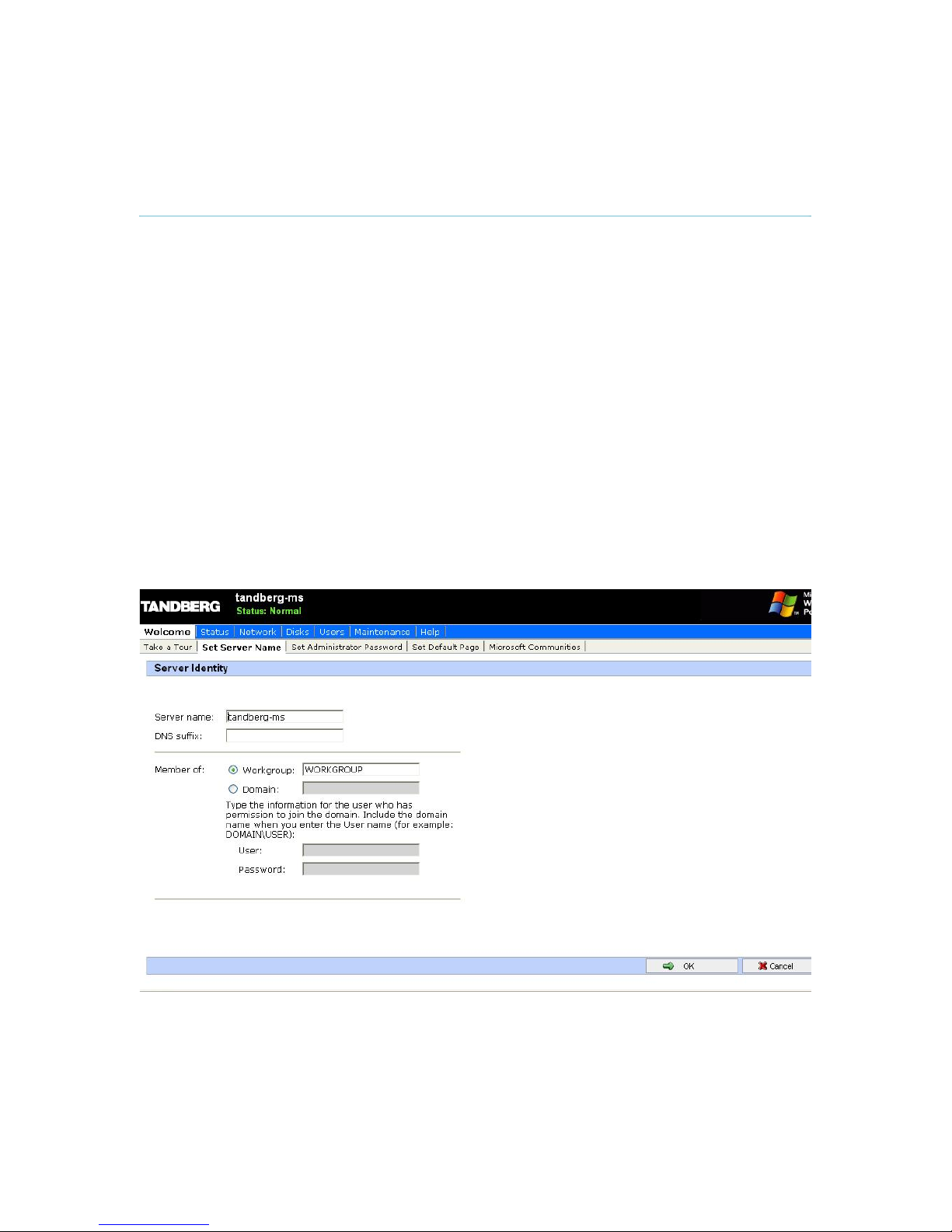
To set the server name and add it to a domain, select the Set Server Name menu item under the
Welcome tab.
Introduction 19
Page 20

TANDBERG Management Server Quick Setup Guide
To set the password of the local administrator account, click the Set Administrator Password
menu item under the Welcome tab.
From the Maintenance tab, you can set the date, time and time-zone.
5.2 TANDBERG
Management Suite Settings
You can access the Web User Interface for the TANDBERG Management Suite (TMS) to
configure TMS settings.
1. Start a web browser and enter the address of the Management Server.
2. When prompted for login, enter the username administrator and password TANDBERG.
3. Click on the Administrative Tools menu item.
20
Page 21

Set the Default Time Zone to where the majority of the TMS users are situated to simplify user
setup.
Select the Administrative Tools > Configuration > Network Settings menu item and scroll down to
the TMS Services section to set the scan range TMS uses to search for new systems. By default
TMS scans the entire network for systems, i.e. sends a broadcast to the address
‘255.255.255.255’.
Introduction 21
Page 22

TANDBERG Management Server Quick Setup Guide
Select the Administrative Tools > Configuration > Mail Settings menu item to set the SMTP server
TMS will use to send emails and the email address these will be sent from.
5.3 Added systems
The TANDBERG Management Server comes with automatic registration of systems enabled.
TMS will therefore after turning it on the first time, search the network for systems. These systems
will be added in folder called ‘Discovered Systems’ under Systems – Navigator, and will be given
a default template that contains the IP-Zone and a phonebook containing all the systems in TMS.
If you wish to turn off automatic registration of systems or change settings on this feature, go to
Administrative Tools Configuration Network and locate the panel called Automatic System
Discovery. Here you will see a drop down for Automatic System Discovery Mode. Set this to ‘Off’.
NOTE: Please make sure that the systems in your network are correctly configured with E.164
alias before installing TMS, to make sure that the phonebook is properly produced by TMS.
22
 Loading...