

Page 1
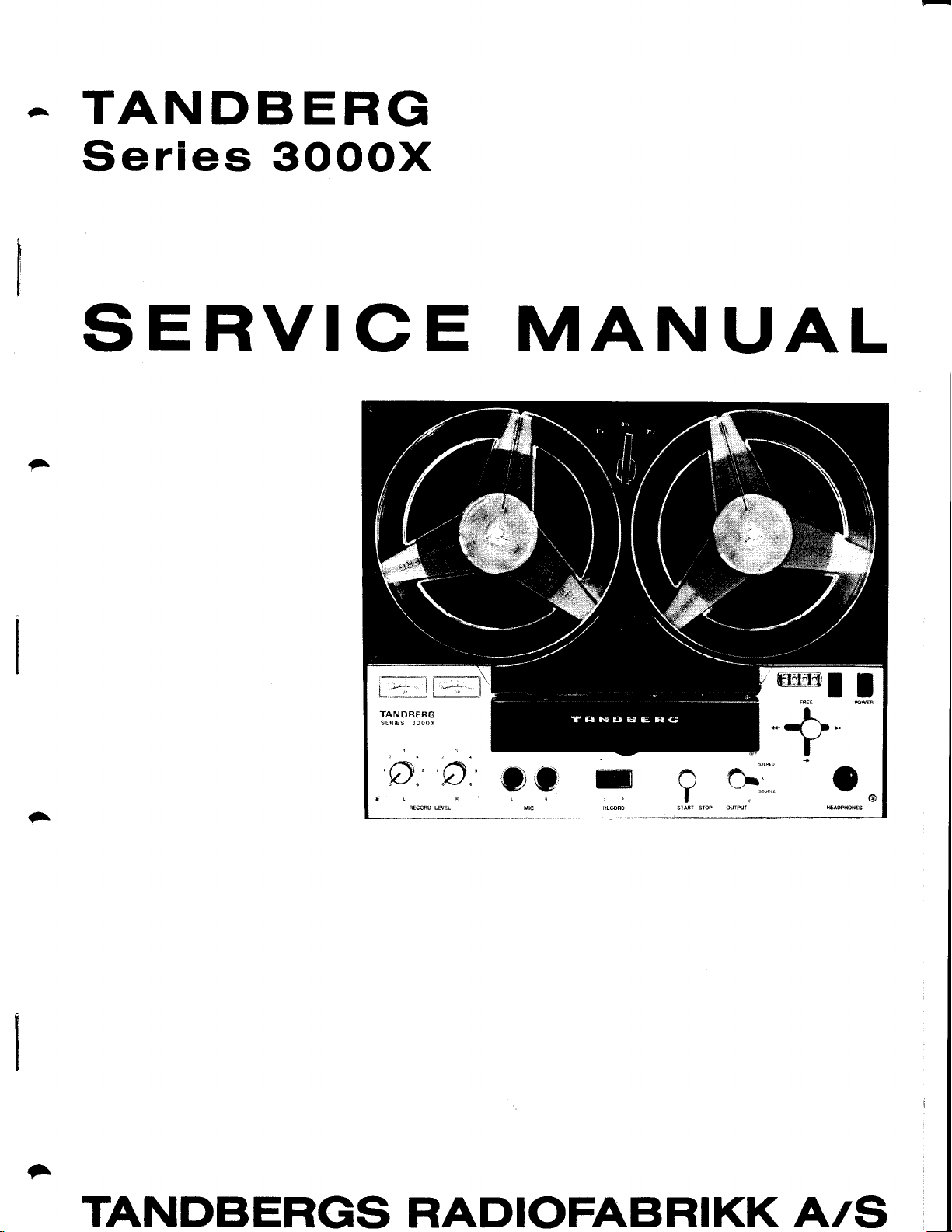
TANDBERG
Series SOOOX
SERVICE
;
ir--I
ll
"--:
";'
t
TANDAERG
MANUAL
I
ryr;
A
*q
r
oc
reCOAO LEEL
ruc
"t
-
;
TANDBERGS
RADIOFABRIKK
A/S
Page 2

-
-
A
^a
Page 3
.G.
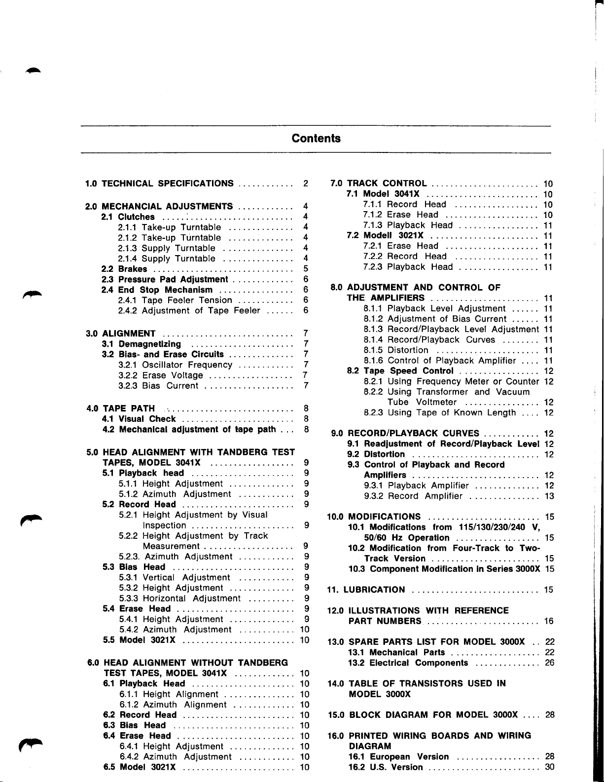
Contents
1.0 TECHNICAL SPECIFICATIONS
MECHANCIAL ADJUSTMENTS
2.0
2.1
Clutches .....:.
2.1.1 Take-up
Take-up Turntable
2.1 .2
2.1.3 Supply
2.1.4 Supply
2.2 Brakes
2.3 Pressure Pad Adiustment . .
F
2.4 End
ALIGNMENT
3.0
3.1 Demagnetlzing
3.2
4.0
TAPE
4.1 Visual Check
4.2 Mechanlcal adjustment ol
5.0 HEAD ALIGNMENT WITH TANDBERG TEST
TAPES, MODEL 3041X
5.1 Playback
5.2
5.3
5.4 Erase Head
5.5 Model
HEAD
6.0
TEST TAPES, MODEL 3041X
6.1 Playback
6.2 Record
6.3 Bias
6.4 Erase
6.5 Model
Stop
2.4.1 Tape Feeler Tension
2.4.2 Adjustment of Tape
Blas-
and Erase Circuits
3.2.1
Oscillator
3.2.2 Erase
3.2.3 Bias Current
PATH
5.1.1 Height Adjustment
5.1.2 Azimuth Adjustment
Record Head
5.2.1 Height Adlustment by
Inspection
5.2.2 Height Adjustment by Track
Measurement . ....
5.2.3. Azimuth Adjustment ...
Bias Head
5.3.1 Vertical Adjustment ....
5.3.2 Height Adjustment
5.3.3 Horizontal Adjustment
5.4.1 Height Adjustment
5.4.2 Azimuth Adjustment
3021X .
ALIGNMENT WITHOUT TANDBERG
Height Alignment
6.1.1
6.1.2 Azimuth Alignment .
Head
Head .
6.4.1 Height
6.4.2 Azimuth Adjustment
3021X
Turntable
Turntable
Turntable
Mechanism .
.
Frequency
Voltage
head
.
.
Head .
Head
.
Adjustment
.
Feeler
. . .
tape
Visual
...
path
. . .
10
10
10
10
10
10
10
10
10
10
10
10
7.0 TRACK
7.1 Model
4
4
4
4
4
4
5
6
6
6
6
7
7
7
7
7
7
8
8
8
I
I
9
9
9
7.2
ADJUSTMENT
8.0
THE
8.2
RECORD/PLAYBACK
9.0
9.1
9.2Dlstortlon.... .........12
9.3
10.0 MoDrFtcATroNS ... 15
9
9
I
9
9
9
9
I
I
10.1
10.2 Modification lrom
10.3
11.
LUBRTCATTON . ...... 15
12.0 ILLUSTRATIONS WITH REFERENCE
PART NUMBERS .. ..... 16
13.0
SPARE
13.1 Mechanical Parts . .. ...
13.2 Electrica! Components . . .... .
14.0 TABLE
MODEL 3OOOX
15.0 BLOCK DIAGRAM FOR
16.0 PRINTED WIRING BOARDS AND WIRING
DIAGRAM
16.1 European Version
16.2
CONTROL
3041X
7.1.1
Record Head
7.1.2
Erase Head .
7.1.3
Playback Head
Modell 3021X
7.2.1 Erase
7.2.2 Record
7.2.3 Playback
AMPLIFIERS
8.1.1 Playback Level
8.1.2 Adjustment
8.1.3 Record/Playback Level
8.1.4 Record/Playback
8.1.5 Distortion
8.1.6
Control
Tape Speed Control
8.2.1 Using Frequency Meter
8.2.2 Using Transformer
Tube Voltmeter ..
8.2.3 Using Tape of Known Length
Readjustment
Control
Ampliliers
9.3.1 Playback Amplifier ....
9.3.2 Record Amplifier .........
Modilications from
50/60 Hz Operation . .. . 15
TrackVersion... ......15
Component Modification in Series 3000X 15
PARTS LIST FOR MODEL 3OOOX .. 22
OF
.
.
Head .
Head
Head
AND
CONTROL
Adjustment ......
Bias
of
of Playback
CURVES
Record/Playback
ol
Playback
of
TRANSISTORS USED
and Record
Four-Track to Two-
MODEL SOOOX . ... 28
OF
Current ...... 11
Curves ... ..... 11
Amplifier .... 1'l
and
11511301230/240
Adiustment 11
........ 11
or Counter 12
Vacuum
...... . 12
.... ...
IN
10
10
'10
10
11
11
11
11
11
... 11
11
.... 12
.... 12
..... 12
Level
12
12
12
...
13
V,
22
26
28
U.S.
Version
30
Page 4
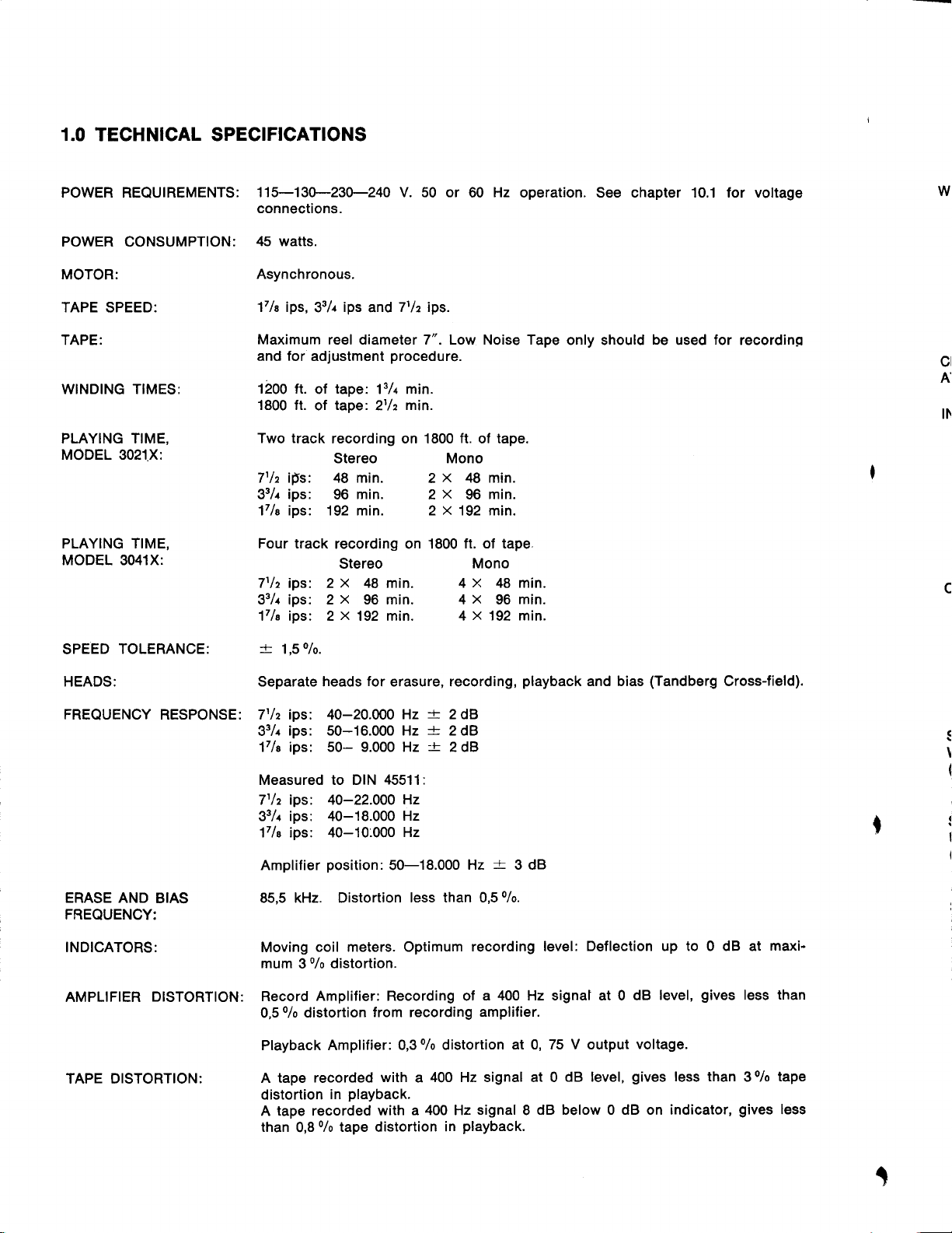
1.0 TECHNICAL SPECIFICATIONS
POWER REQUIREMENTS:
POWER CONSUMPTION:
MOTOR:
TAPE
SPEED:
TAPE:
WINDING
PLAYING TIME,
MODEL 3021X:
PLAYING TIME, Four track
MODEL 3041X:
TIMES:
115-130-230-240 V. 50 or
connections.
45 watts.
Asynchronous.
17le ips,
Maximum reel diameter 7". Low Noise Tape
and
1200 ft.
1800 ft.
Two track
7t/z ips: 48 min.
33/,r
17la ips: 192 min. 2 X 192 min.
71/z ips: 2 x 48 min. 4 x 48 min.
33/r ips: 2 x 96 min. 4 x 96
17le ips: 2 x 192 min. 4
33/r
for
adjustment
of
of
ips:
Hz
60
ips
tape;
tape:
recording on 1800 ft. of tape.
Stereo Mono
96
recording on 1800
Stereo
and
131 min.
2t/z
min.
7tlz ips.
procedure.
min.
x
2
2 x 96
48 min.
ft. of tape.
x
operation. See chapter 10.1 for voltage
min.
Mono
min.
192 min.
only should
be
used
for
recordinq
Wl
cl
A
SPEED
HEADS: Separate heads
FREQUENCY RESPONSE: 7t/z ips: 40-20.000
ERASE AND
FREQUENCY:
INDICATORS: Moving
AMPLIFIER
TAPE DISTORTION:
TOLERANCE:
BIAS
DISTORTION:
-+
1,50/0.
for
ips: 50-16.000 Hz
33/r
17e ips: 50- 9.000 Hz
Measured to DIN
7t/z ips: 4O-22.0O0
33/r ips: 40-18.000
17la ips: 40-10.000
Amplifier
85,5 kHz. Distortion
mum
Record
0,5
Playback Amplifier: 0,3
A tape
distortion
A tape
than
position:
coil meters. Optimum
o/o
3
distortion.
Amplifier: Recording of
0/o
distortion
recorded
in
recorded with
0/o
0,8
45511:
50-18.000
from recording
with a 40O Hz signal at 0
playback.
tape distortion
erasure, recording,
-+
Hz
Hz
Hz
2dB
-+-
2dB
-+
2dB
Hz
-+
Hz
less than 0,5 %.
recording level:
a 400 Hz signat at 0 dB
amplifier.
0/o
distortion
a 400 Hz
signal 8 dB below 0 dB on indicator,
playback.
in
3 dB
at 0, 75 V output
playback
dB level,
and bias
Deflection up to 0 dB at
(Tandberg
level,
voltage.
gives
less than
Cross-field).
gives
less
30/o
gives
C
!
(
fi
(
maxi-
than
tape
less
i
Page 5
-
a
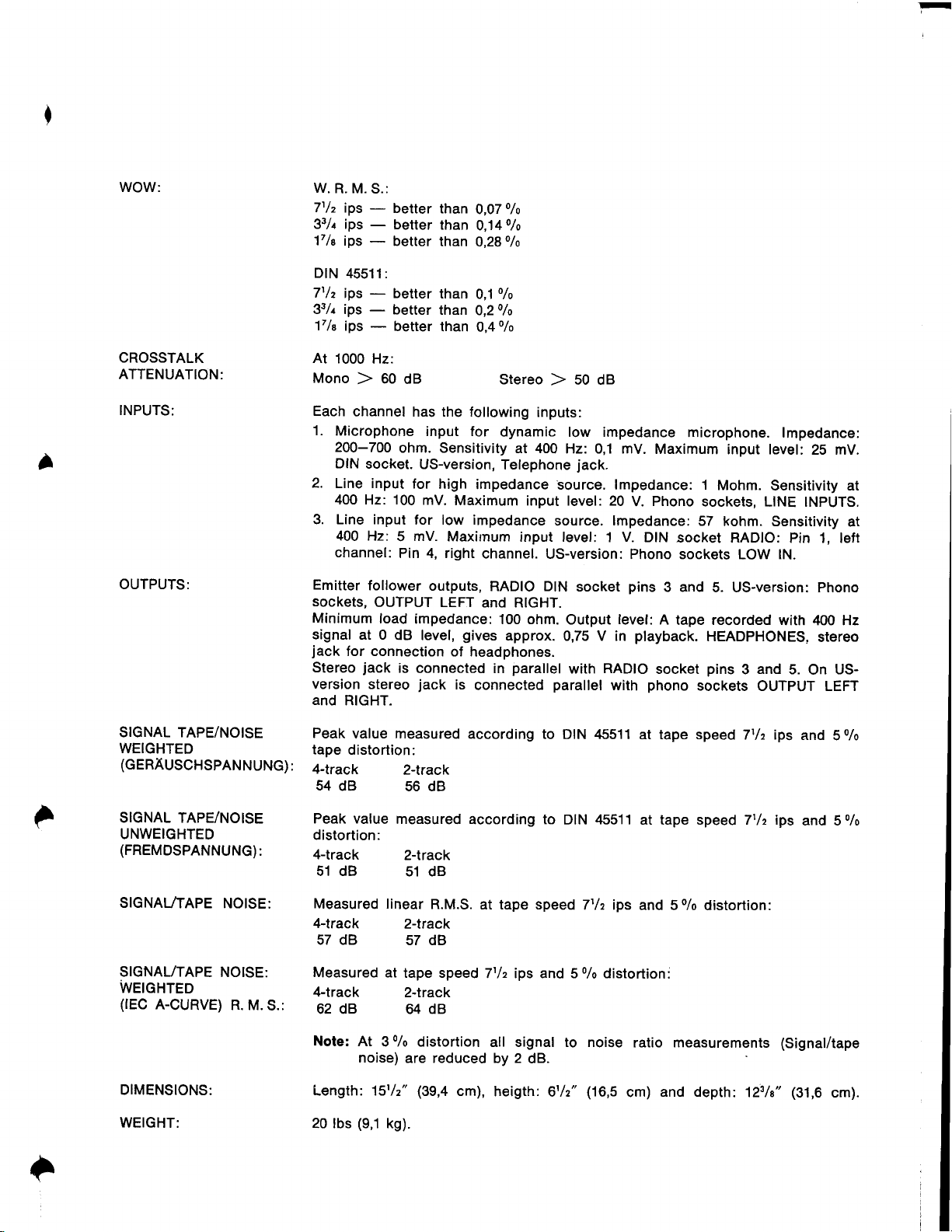
WOW:
CROSSTALK
ATTENUATION:
INPUTS:
OUTPUTS:
W.
R. M. S.:
7t/z
ips
33/r ips
17le
ips
DtN
45511 :
71/z
ips - better
33/r ips
17le
ips
At
1OOO
Mono
Each
1.
Microphone
200-700
DIN
2.
Line input
400 Hz: 100
3. Line input
400 Hz:
channel:
Emitter
SocKetS,
Minimum
signal
jack
for connection
Stereo
version
and
RIGHT.
better
-
-
-
-
Hz:
60
)
channel has the following
socket.
follower
OUTPUT
load
at 0
jack
stereo
than
better
than
better
than
than
better
lhan
better
than
dB
input for
ohm. Sensitivity
US-version,
for
high
mV.
for low impedance
mV.
5
Pin 4, right
outputs,
LEFT
impedance:
dB level,
is connected
jack
o/o
0,07
0,140/o
0,280/o
o/o
0,1
O,2o/o
0,40lo
Stereo
dynamic low impedance
Telephone
impedance
Maximum
Maxirnum
channel.
RADIO DIN
and RIGHT.
100 ohm.
gives
approx.
of
headphones.
in
is
connected
SO OA
)
inputs:
at 400
parallel
Hz: 0,1 mV.
jack.
source. lmpedance: 1
input level: 20
socket
Output
RADIO
with
lmpedance:
with
source.
input level: 1 V.
US-version:
0,75 V in
parallel
microphone.
Maximum
Phono
V.
DIN
Phono sockets
pins
level:
playback.
phono
sockets,
57
socket RADIO:
3 and
A
tape recorded
socket
sockets
lmpedance:
input level:
Mohm.
LINE lNpUTS.
kohm. Sensitivity
LOW
5. US-version:
HEADPHONES,
pins
and
3
OUTPUT LEFT
25 mV.
Sensitivity at
Pin 1, left
lN.
with 400 Hz
5.
On
at
phono
stereo
US-
SfGNAL TAPE/NOISE
WEIGHTED
(GERAUSCHSPANNUNG):
SIGNAL TAPE/NOISE
UNWEIGHTED
(FREMDSPANNUNG):
SIGNAL/TAPE
SfGNAL/TAPE
NOISE:
NOISE:
Wetonreo
(lEC
A-CURVE)
DfMENSIONS:
WEIGHT:
R. M.
S.:
Peak
value measured
tape
distortion:
4-track
54
dB
Peak value
distortion:
4-track
51 dB
Measured linear
4-track
57 dB
Measured at
4-track
62 dB 64 dB
Note:
At
noise)
Length: 151/2"
(9,1
20 lbs
2-track
56 dB
measured
2-track
51 dB
2-track
s7 dB
tape speed
z-track
0/o
3
distortion
are reduced by 2
(39,4
kg).
according
according to
R.M.S.
cm),
to DIN 45511
DIN 45511
at tape speed
7t/z ips and 5
all signal to noise
dB.
heigth:
6t/2"
7'lz ips
0/o
(16,5
at tape speed
at tape speed 7t/z ips
o/o
and 5
distortion:
ratio measurements (Signal/tape
and depth:
cm)
71/z ips
distortion:
123la"
(31,6
and
5olo
and 5o/o
cm).
Page 6
2.0 MECHANICAL
ADJUSTMENTS
2.1
Glutches
Control
Note:
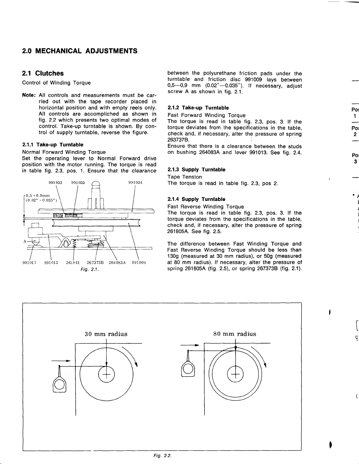
2.1.1
Normal
Set the
position
in
of
All
controls and
ried out
horizontal
All
tig. 2.2
control.
trol of supply
Take-up
Forward Winding
operating lever to
v.rith the motor running. The
table tig. 2.3,
0.5 - 0,9mm
(0.02t'
-
0.035'r
Winding
controls
Torque
measurements must
with the tape recorder
position
which
Take-up
Turntable
pos.
)
and
accomplished
are
presents
turntable
turntable, reverse the
Torque
1.
Ensure that the
be car-
placed
with empty reels only.
shown
as
two optimal modes
is shown. By con-
figure.
Normal
Forward
torque is
drive
read
clearance
between
turntable
0,5--O,9 mm
screw
A as shown
in
2.1.2
Take-up Turntable
in
Fast
of
Forward Winding
The
torque is read in
torque deviates
check and,
263737B.
Ensure that
on bushing
2.1.3
Supply Turntable
Tape
Tension
The
torque
2.1.4
Supply Turntable
Fast
Reverse
The torque is read in table fig.
torque deviates
check
and, if
2618054.
polyurethane
the
and friction
(0.02"-0.035").
in
from the
if necessary,
there is
2640834
read
is
Winding
lrom
necessary,
See fig. 2.5.
friction
disc 991009
lf
fig.
2.1.
Torque
table fig.
specifications
alter the
a clearance
and lever
in table
Torque
the specifications
alter the
necessary,
2.3,
pressure
between the
991013.
2.3,
fig.
2.3,
pressure
pads
lays
pos.
in
See
pos
pos.
in
under
between
adjust
3. lf the
the table,
of
spring
studs
fig.
2.
3. lf
the
table,
of
spring
the
2.4.
the
*
1
Pot
2
Pot
3
,l
I
a
I
i
(
i
991017
9910r3
261841 2673?38
Fig. 2.1 .
mm
30
2640834'
radius
991009
The difference between
Fast
Reverse
(measured
1309
at 80 mm radius). lf necessary, alter the
spring 261805A
Winding
at 30 mm
(fig.
80 mm
Fast Winding
Torque
radius),
2.5),
or spring
radius
should be less than
509
or
2673738
Torque and
(measured
pressure
(fig.
ot
2.1).
t
t
Fig 2.2.
Page 7
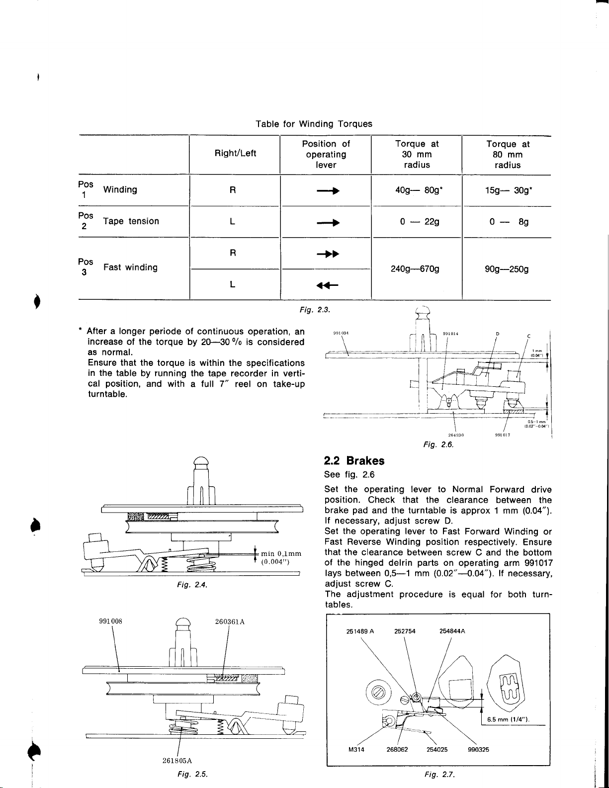
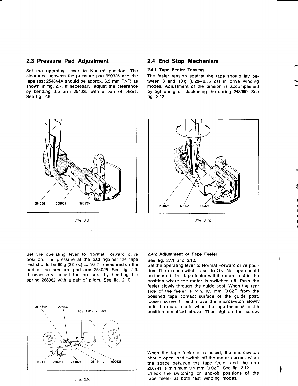
Table for Winding Torques
Torque
tit
winding
Pos
tape rensron
2
Pos
Fast winding
3
t
*
After a longer
increase of the torque
as normal.
Ensure
in the
table
position,
cal
turntable.
periode
that the
by
and with
of continuous operation,
by 2G-30
torque is within the
running
the tape recorder in vertia tull 7" reel on take-up
0/o
is
considered
specifications
Fig. 2.3.
an
C
mm
30
radius
at
Torque
at
80 mm
radius
159-
309-
o- 8g
909-250g
264930
Fig. 2.6.
991 01
?
2.2 Brakes
See fig. 2.6
Set the operating lever to Normal
position.
brake
I
min 0,lmm
(0.004,')
Fig.
2.4.
lf necessary,
Set the operating lever to Fast
Fast
that the
of the hinged
lays between
adjust screw
The adjustment
tables.
Check
pad
and the turntable is
Reverse Winding
clearance between screw
A
251489
that the
adjust screw D.
delrin
0,5-1 mm
C.
procedure
clearance between
position
parts
on
(0.02"-4.O4"
operating arm 991017
is
Forward
approx 1 mm
Forward Winding
respectively.
C and the bottom
).
for both turn-
equal
(0.04").
Ensure
lf
necessary,
drive
the
or
@
261 805A
Fig.
2.5.
Fig.
2.7.
Page 8
Pressure Pad
2.3
the
Set
clearance
tape rest 254844A
shown
by bending
See
operating lever
between
in fig.
2.7.
the arm
fig. 2.8.
Adjustment
to Neutral
pressure
the
should be approx. 6,5 mm
lf
necessary, adlust the clearance
254025 with
2.8.
Fig.
position.
pad
990325 and the
pair
a
(tlr")
of
pliers.
The
as
2.4
End
2.4.1
Tape
The
feeler tension
tween
modes.
by
lig.
8 and 10
Adjustment of
tightening or
2.12.
Stop
Feeler
Mechanism
Tenslon
against the tape should lay
g (0.28-0.35
the
tension is
slackening the spring 243990.
Fig.2.10.
in drive winding
oz)
be-
accomplished
See
I
l1
a
(
t
a
I
a
the operating
Set
position.
rest should
of the
end
lf
necessary, adjust the
spring
268062
zzl
pressure
The
be 80
pressure
with a
252754
g
/:\
(@,
tM3l4
lever
(2,8
pad
pair
Fig. 2.9.
Normal
to
at the
-+
ozl
arm
pressure
pliers.
of
80s
12.82
l,
a-\\
',-/
Forward drive
pad
against the tape
0/0,
10
measured on the
254025.
by bending
See
!
ozl
See fig.
fig. 2.10.
2.9.
the
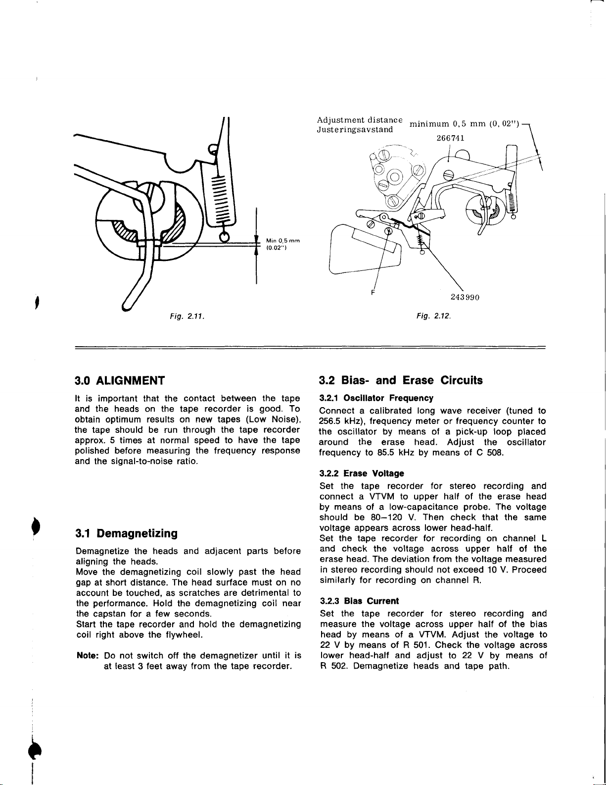
2.4.2 Adjustmenl of Tape Feeler
fig. 2.11 and 2.12.
See
Set the operating
tion. The
be inserted.
position
feeler
side of the
polished
loosen
until the
position
When the
should open,
the space
266741
Check
tape feeler at
mains
where
slowly
tape contact surface
screw
motor starts when the tape
specified above. Then tighten
is minimum
the switching on
lever to
switch is set to ON. No tape should
The tape feeler will
the
through the
feeler is
F, and move the microswitch slowly
tape feeler is released,
and switch off
between
both
Normal Forward drive
motor
0,5 mm
is switched
guide
min. 0,5
the
tape
(O.O2").
and-off
fast
winding
the
posi-
therefore
post.
mm
of the
motor current when
feeler
modes.
rest in
off. Push
When the rear
(0.02")
the microswitch
See
positions
from
guide post,
feeler is
and the arm
in
the
screw.
fig. 2.12.
of
the
the
the
the
the
Page 9
Min
0,5
(o.02"
Adjustment
Juste ringsavstand
mm
l
distance
minimum
266741
mm
0,5
243990
(0,02rr)
v
2.11.
Fig.
3.0 ALIGNMENT
It is
important that
and the heads on the tape recorder is
obtain optimum results on new tapes
the tape should be run
approx. 5 times at normal speed
polished
and
3.1
Demagnetize
aligning
Move
gap
account be touched,
the
the
Start
coil right above the flywheel.
Note:
before
signal-to-noise
the
Demagnetizang
the
the heads.
the demagnetizing
at short distance.
performance.
capstan for a
tape
the
not
Do
least
at
the contact between the tape
(Low
tape recorder
through
measuring
ratio.
heads
Hold
recorder and
switch off the demagnetizer
3 feet away
and
coil slowly
The head
as scratches are
the
few
seconds.
from the tape recorder.
the
to have the tape
the frequency response
adjacent
surface
demagnetizing
hold
parts
past
detrimental to
demagnetizing
the
good.
Noise),
before
the head
must
on
coil
until it
To
no
near
is
Fig. 2.12.
Bias-
3.2
Oscillalor Frequency
3.2.1
Connect a calibrated
256.5 kHz), frequency meter
the
oscillator
around the erase head.
frequency to
3.2.2 Erase Voltage
Set
the
connect a VTVM to upper half of the erase head
by means of
should be 80-120 V.
voltage appears across
Set the tape
and check
erase
in
stereo
similarly for
Bias
3.2.3
Set the tape
measure the
head by means
22 Y by means
lower
R
502. Demagnetize heads
and Erase Circuits
long wave receiver
by means
kHz by means of
85.5
tape recorder
low-capacitance
a
Then
recorder for
voltage
the
head.
recording
head-half and
deviation from
The
should not exceed 10
recording on channel
Current
recorder for
voltage across upper half of the bias
VTVM. Adjust
of a
of R 501 . Check the voltage across
adjust to
(tuned
frequency
or
pick-up
of a
Adjust the oscillator
for
stereo recording
probe.
check ihat the same
lower
head-half.
recording
across upper half of
voltage
the
stereo recording and
22
tape
and
loop
C 508.
The voltage
on
R.
the
Y by
path.
counter
channel L
measured
V.
voltage to
means of
placed
and
the
Proceed
to
to
Page 10
TAPE PATH
4.0
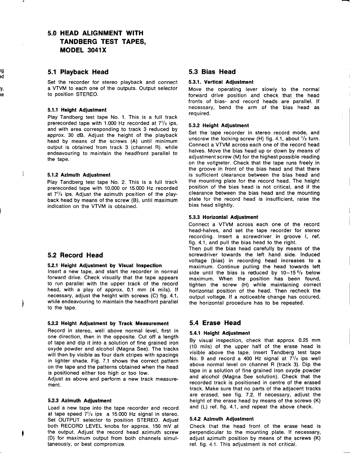
4.1 Visual Check
the recorder with a tape,
Load
operating
position.
the
head
record
parallel
Operate
tape
rubber without
pressure
the
the tape touches the flanges of the
when the recorder is in normal
as the drive mechanism is engaged. The
however,
lever
slowly
Check that the
height adjustment
guide
plate,
base
head.
to the
runs within
Also check that
record
the
start/stop
wheel.
posts
by no means bulge at the flanges.
to the normal
bias head
screws
presses
nor
head.
knob, and
the rims of
flickering on
Check that
is correct.
lt
(C)
the
the
the
neither
height
can be tolerated that
forward
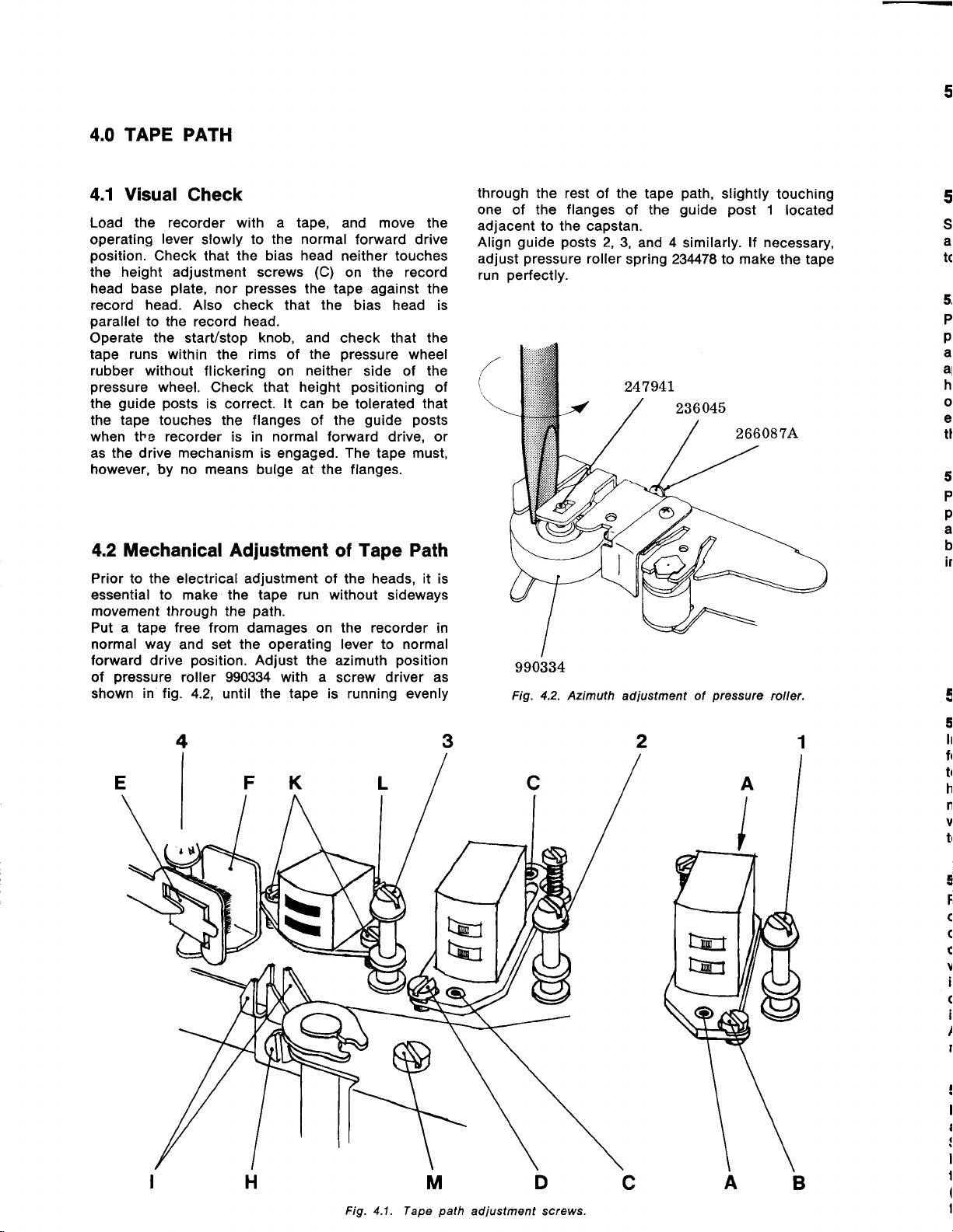
4.2 Mechanical Adjustment
Prior to the electrical adjustment of
essential to make the tape run without
movement
Put a tape
normal way
forward drive
pressure
of
shown in tig. 4.2, until the tape is running evenly
through the
free
and set
position.
roller
path.
from damages on the recorder in
the operating lever to normal
Adjust
990334
the azimuth
with a
move
and
forward drive
neither touches
on the record
tape against the
bias head is
check that the
pressure
side of the
positioning
guide posts
tape
Tape Path
of
heads, it is
the
screw
the
wheel
of
drive, or
must,
sideways
position
driver as
through
one of the
adjacent
Align
adjust
run
the rest of the
to the capstan.
guide posts
pressure
perfectly.
(
990334
Fig. 4.2. Azimuth
flanges
2,
roller
path,
tape
guide post
the
of
3,
and 4 similarly.
spring
adiustment
234478 to make
ol
slightly
lf necessary,
pressure
touching
1
located
the tape
roller.
5
$,
a
tc
5.
P
pl
al
al
hr
o
el
tt
5,
P
p
a
b
ir
E
5
4
Ir
ft
tt
h
n
v
tt
I
F
C
(
c
v
I
(
I
I
I
Fig. 4.1 . Tape
MD
path
adiustment screws.
Page 11
HEAD ALIGNMENT WITH
5.0
TANDBERG
MODEL
TEST
3041X
TAPES,
rg
)d
v,
)e
Playback
5.1
the recorder
Set
a VTVM to each
position
to
Helght
5.1.1
Tandberg
Play
prerecorded
and with area
approx. 30 dB. Adjust the height of the
head by means
output
endeavouring to maintain the headfront
the tape.
5.1.2
Play
prerecorded
al 7t/t ips.
back head by
indication
5.2
5.2.1
forward
to run
head,
necessary,
while endeavouring to maintain
to the tape.
is
obtained from track
Azlmuth
Tandberg
on the VTVM is obtained.
Record
Height
Insert a new
drive. Check
parallel
with
Head
stereo
for
of the outputs. Output selector
one
STEREO.
Adiuslment
test tape No. 1. This
tape with 1.000 Hz recorded at
corresponding to track 3
the
of
Adjustment
test tape No. 2. This
tape with 10.000 or 15.000
Adjust the azimuth
means of the screw
playback
screws
3
position
and
is
(A)
until minimum
(channel
is
Hz
(B),
until maximum
Head
Adiustment by Visual
tape, and start the recorder
visually
with the upper
play
a
adjust the
of approx.
height
Inspectlon
that the tape
track of the record
mm
0.1
with
screws
the headfront
a full track
reduced
a full track
of the
connect
71/z
playback
R), while
parallel
recorded
play-
in normal
appears
(4
mils). lf
(C)
fig.
parallel
ips,
by
to
4.1
5.3 Bias Head
5.3.1. Vertlcal
Move
the operating lever slowly to
forward
fronts
necessary, bend
required.
5.3.2 Height
Set the tape
unscrew
Connect a VTVM
halves.
adjustment screw
on the voltpeter.
the
is
the
position
clearance
plate
bias head slightly.
5.3.3 Horlzontal Adjustment
Connect a
fig.
Then
screwdriver towards the
voltage
maximum.
,
of
groove
sufficient clearance between the
mounting
for the
head-halves,
recording. Insert a
4.1, and
pull
side until
maximum. When
tighten
horizontal
output voltage.
the
horizontal
Adjustment
position
drive
bias-
and record heads are
Adjustment
recorder
locking
the
the
Move
in lront
plate
the bias head is not critical, and if the
of
between
record
VTVM
and set the
pull
the
bias head carefully
(bias)
the screw
in recording head increases to a
Continue
the
bias is reduced by 10-150/o below
position
lf
procedure
normal
the
and check that the head
the arm of the bias
stereo
in
screw
across each one of the record
bias head
(M)
for the
Check that
of the
for
the
the bias head and
head is insufficient, raise the
across
the bias head to the right.
the
of the head.
a noticeable change has
each
screwdriver
pulling
position
(H)
while
has
record mode,
(H)
fig.
4.1, about
up
or down by
highest
the
tape runs
bias head
record head. The height
one of the
tape recorder for stereo
in
left
hand side. lnduced
the
head towards
has
maintaining correct
Then
to be repeated.
parallel.
head
means
possible
that there
and
head and
bias
mounting
the
groove
means of the
by
been
recheck
r/z
reading
freely
occured,
as
and
turn.
head
of
in
record
l,
ref.
left
found,
the
ll
Height
5.2.2
Record
direction,
one
of tape
oxyde
will then
in
lighter shade. Fig.7.1
on
the
positioned
is
Adjust as above
ment.
5.2.3 Azimuth
Load a new
at tape speed
Set OUTPUT
RECORD
both
the
output.
(D)
for
taneously,
Adjustment
in stereo,
then in the
and
dip it
powder
by visible
tape
maximum
or best compromize.
into
and alcohol
and the
either
and
Adjustment
tape into the tape recorder
7tl2 ips a 15.000
selector to
LEVEL knobs for
Adjust
by Track Measurement
above normal level,
well
opposite. Cut off a length
a solution
four
as
shows the correct
patterns
too high
perform
the record head
output from
of
(Magna
dark stripes
obtained
or too
new track measure-
a
Hz
position
approx. 150 mV
both channels simul-
first in
grained
fine
See). The tracks
with
when the
low.
and record
signal
STEREO. Adjust
azimuth
iron
spacings
pattern
head
in stereo.
at
screw
Erase Head
5.4
5.4.1 Helght
By visual
(10
mils) of the upper half of
visible
No. 9 and record a 400 Hz
above normal
tape in a solution of fine
and alcohol
recorded
track.
are
erased,
height
(L)
and
5.4.2 Azlmuth
Check that
perpendicular
adjust
ref.
fig. 4.1.
Adjustment
inspection,
above the tape. Insert
level
(Magna
is
track
sure that no
Make
see fig. 7.2. lt necessary,
of the erase
fig.4.1, and
ref.
Adjustment
the head
to the
azimuth
position
This
check
on channel
grained
solution).
See
positioned
parts
head
by
repeat
front
mounting
by
adjustment
that
approx.
the
erase
Tandberg test tape
signal
in
means
ol the
means
is not
at 7tlz
(track
R
iron
oxyde
Check
centre of the
the
of
adjacent
of the screws
the
above
erase
plate.
lf
of the. screws
critical.
0.25 mm
head is
ips well
Dip the
3).
powder
that the
erased
tracks
check.
head
the
(K)
is
(K)
adjust
necessary,
Page 12
<
5.5 Model 3021X
The
alignments
the model
5.1.1, which is superseded
5.2.1 , which is superseded
HEAD ALIGNMENT
6.0
TANDBERG
specified in
3021X with the exception of
TEST TAPES,
para.
by 6.1.1 and
7.2.2.
by
WITHOUT
MODEL 3041X
6.1 Playback
6.1.1 Helght Alignment
The
height of the
height
adjustment
edge of the tape shall run
of the
6.1.2 Azimuth Alignment
Set OUTPUT selector to
Play
a VTVM connected to each output.
tion
screw
obtained on the output meters.
head
back a standard
playback
the
of
(B)
Head
playback
screws
lamination
fig.
ref.
(A), ref.
flush with the
for channel
position
azimuth
head
by
4.1,
until
head is aligned by
fig.
alignment tape with
the
azimuth
maximum reading is
valid
are
5.0
paragraph
paragraph
4.1. The upper
upper
L.
STEREO.
Adjust the
adjustment
for
the
part
posi-
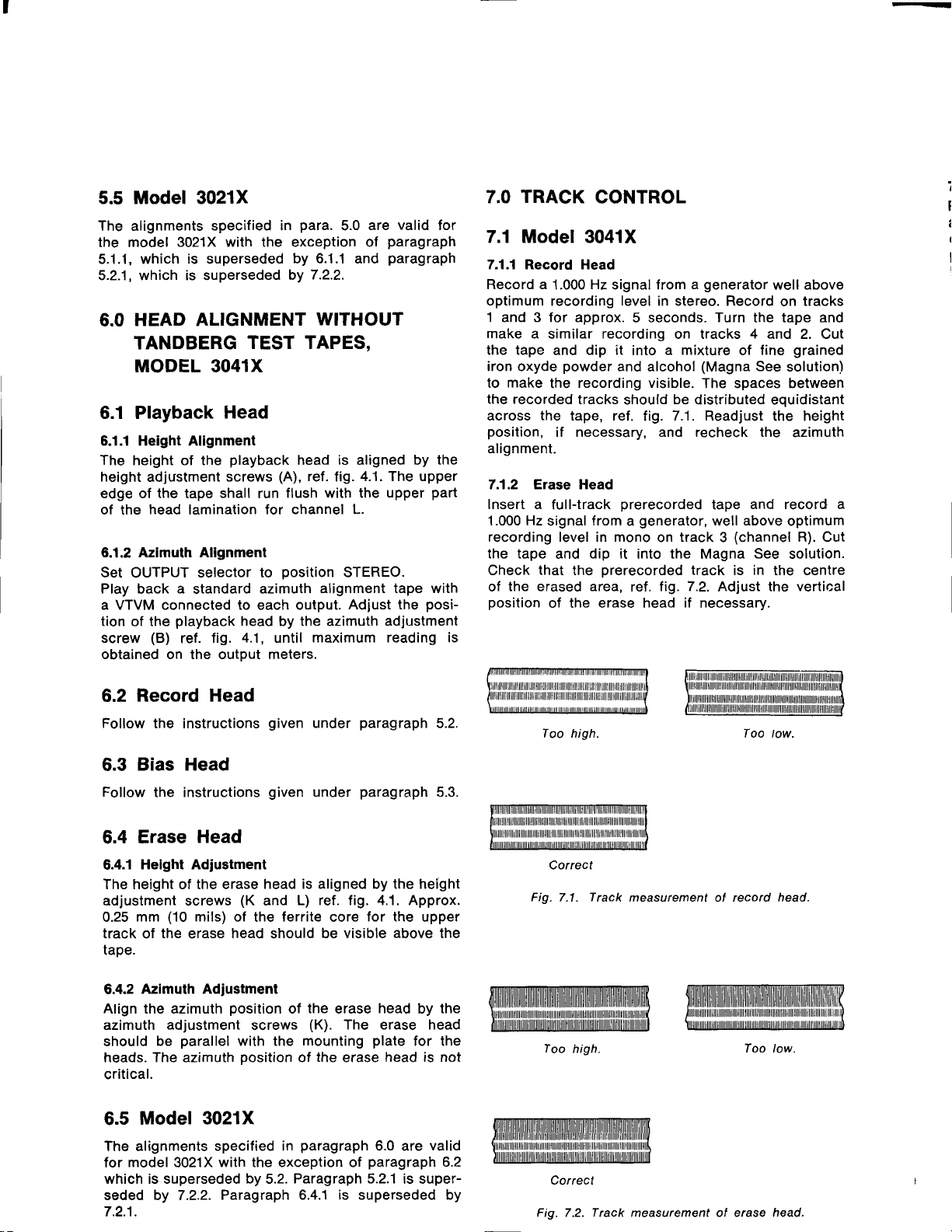
7.0 TRACK
7.1 Model
7.1.1 Record Head
Record a
optimum
1 and 3 for
make a
the tape
iron oxyde
to
the recorded
across the tape, ref.
position,
alignment.
7.'1.2 Erase Head
lnsert a
1.000 Hz
recording level in mono
the tape
Check
of
position
similar
make
signal
that
the erased area,
of the erase head
CONTROL
3041X
Hz
1.000
recording
and
powder
the
if necessary, and recheck the
full-track
and
signal from
level
approx. 5 seconds. Turn the tape and
recording
dip it
into
and
recording visible.
tracks
the
should
prerecorded
from
dip it
generator,
a
into
prerecorded
ref.
generator
a
in stereo. Record
on tracks 4 and 2. Cut
a mixture
alcohol
be
7.1.
fig.
track
on
the
1i9.7.2.
if
(Magna
The spaces between
distributed equidistant
Readjust the height
tape
well above
Magna
track
necessary.
fine
of
See
and record a
(channel
3
See
is in the centre
Adjust the
above
well
tracks
on
grained
solution)
azimuth
optimum
R). Cut
solution.
vertical
Record Head
6.2
Follow
6.3
Follow
6.4
6.4.1
The height of the erase
adjustment screws
0.25
track of
tape.
6.4.2
Align the azimuth
azimuth
should
heads.
critical.
6.5
The alignments
for
which is superseded
seded by 7.2.2.
7.2.1.
the instructions
Bias Head
the instructions
Erase
Helght Adjustment
mm
Azimuth Adjustment
Head
(10
mils) of
the
erase
adjustment
parallel
be
The
azimuth
head
position
with the
Model 3021X
specified in
model
with the exception of
3021X
Paragraph 6.4.1 is superseded by
(K
the
screws
position
by
given
under
given
under
head is aligned by the height
L) ref. fig. 4.1. Approx.
and
lerrite
should
the
of
(K).
mounting
of
paragraph
Paragraph 5.2.1
5.2.
paragraph
paragraph
for the
core
be visible
erase
The erase head
the
erase
above
head
plate
head is not
6.0 are
paragraph
5.2.
5.3.
upper
the
by the
for the
valid
6.2
is super-
Too high. Too
Correct
Fig.
Fig. 7.2. Track
7.1 .
Too
high.
Cotrect
Track
measurement
measurement
record head.
of
ol erase head.
Too
low.
low.
Page 13

te
(s
td
Tt
rd
t)
rn
It
It
h
2
n
t
t.
I
I
7.1.3
Playback
Record a 1.000 Hz signal on
a 500 Hz signal on
optimum recording
position
back track 2
Raise the
heard. Lower the
is heard. Recheck
Head
STEREO.
(channel
playback
playback
track
track
levels. Set OUTPUT selector
Turn the tape around
head
the azimuth
(channel
3
R).
No signal should
if the
head if the 500 Hz signal
R) well
1.000 Hz signal is
position.
L) and
above
and
be heard.
(channel
1
to
play
7.2 Model 3021X
7.2.1 Erase Head
The height of the erase
adjustment screws
a 1.000 Hz
recording level
the tape in the Magna See solution and check
the tracks are distributed symmetrically across
Readjust
tape.
necessary.
7.2.2 Record Head
The height
height
signal in
on a full-track
Magna See solution and
distributed symmetrically across the tape. Readlust
the erase and the record heads. if necessarv.
7.2.3 Playback Head
The
height of the
height adjustment screws
parallel
channel L. Readjust the azimuth
signal
a full-track
on
the erase and
of the
adjustment screws
stereo
with
record head is aligned
well
prerecorded
playback
the upper
8.0 ADJUSTMENT
THE
OF
8.1.1 Playback Level Adjustment
Connect a VTVM
OUTPUT
recorder lor 7t/z
No. 4 and adjust R451
reading
on both vacuum tube voltmeters.
AMPLIFIERS
to each one of the outputs, and set
selector to
ips
head is aligned by the
(K
and L) ref. fig. 4.1. Record
in stereo well above optimum
above
playback
prerecorded
the record heads, if
(C).
Record a 1.000 Hz
optimum recording level
tape. Dip the tape in
check
edge
AND
position
(L)
that the tracks are
head is aligned by the
(A).
The
the lamination for
of
position
CONTROL
STEREO. Set the
Tandberg
of
and R351
tape. Dip
tape shall
if necessary.
(R)
that
the
the
by
run
test tape
for
0.7
mum deflection
maximum on right channel
Note: The 2-lrack
individually
The values ot C5O2, C503, C515 and C516 are
labelled on the bias- and erase
tively. The capacitances are
Upper number
8.1.3 Record/Playback
Connect
a new tape and record a
rator at
tion SOURCE. Adjust the
indication of 0,7
for a 0 dB reading on
R333 for
OUTPUT selector to
R451
8.1.4
Ref.
curves.
8.1.5 Dlstortion
Connect signal
and distortion
both channels. OUTPUT
Set the tape
Record Level
cators. Check
distortion exceeds 30/o
indicator, ref.
8.1.6 Control of
Connect
selector to
Play back
prerecorded
250-10.000-5.000-1.000-100-50-250
at
N. A. B.
0-
quencies
in level between the two channels
than 3 dB.
V
a VTVM to each one of the outputs.
7t/z
(L)
Record/Playback Curves
paragraph
a VTVM to each one of
71/z ips tape speed.
standard.
+ 4 dB, 5 kHz - 1
on left channel VTVM, and R502 to
model is also equipped with
tuned bias- and erase
refers to upper track.
Level
400 Hz
A-test.
ips in
volt
the same
and R351
9.0
generator,
meter to outputs.
recorder for stereo
controls
distortion to be
paragraph
Playback
position
Tandberg
tape with the following
The output tolerances
have tolerances
OUTPUT
both
at
left record level indicator and
reading on right indicator. Set
position
(R)
to 0,7
for
control
400 Hz 0.5
selector to
to 0 dB deflection
readjust recording level and
8.1.3.
STEREO.
test
The
-
VTVM.
heads.
heads
respec-
given
Adjustment
from a
signal
selector to
input levels for a VTVM
outputs.
STEREO and adjust
V indication
of record/playback
Record in B-test
Amplifier
the outputs. OUTPUT
No. 3. This is a
tape conforms
+
3dB.
t
2 dB. The difference
Adjust
V, to High Input
position
recording. Adjust
less
than 3
frequencies:
Hz recorded
are: 10 kHz:
The
should be less
pF.
in
Insert
gene-
posi-
R433
VTVM.
on
STEREO.
on indi-
0/0.
full
track
with the
fre-
other
on
lf
8.1.2 Adjustment
Insert
a new reel
Connect a VTVM
generator
generator
selector to STEREO. Set the tape recorder for
stereo recording. Adjust the Record Level
to 75 mV
to HIGH Input terminals and set the
for 1.000 Hz
deflection on VTVM. Adiust
Bias
of
good
of
to Output
Current
quality
terminals, and signal
0.5 volt.
and
tape
(Low
R501
Set
Control
to maxi-
Noise).
output
Tape Speed Control
8.2
Using Frequency
8.2.1
Set OUTPUT selector
Connect a frequency
play
and
at
speed is indicated in
7tlz ips
back Tandberg
tape speed.
Meter
or Counter
position
to
meter
test tape No. 11
Difference from
0/0.
Tolerance:
L.
counter to
or
correct
-r-
1,50/0.
Output
(1.000
tape
L
Hz)
Page 14

Uslng
8.2.2
Connect
Translormer
a transformer
Hz and a WVM to
fig.
in
8.1,
dotted
version.
Tandberg test tape
back
Hz)
50
tape
ips
OUTPUT selector to
Set
19
No.
or
speed.
and Vacuum
115/0.S V
Output
and the
line indicates
No.
10 a
(mains
a
frequency 60
or
phono
Deviation from correct tape speed
across the VTVM.
Clock
the time
for
complete
10
meter needle.
Read the speed deviation in
to this
particular
time from the nomogram in
per
cent corresponding
Brake left hand turntable slightly
speed is too high
indicates too
At 33/r ips,
low
play
Tandberg test
or
tape
low.
too
speed.
Increased deviation
tape
mains frequency). Proceed as for
speed accuracy.
Speed tolerance: + 1,50/0.
v.T.v.M
Tube Voltmeter
230/0.5
mains
socket on
position
(mains
50i60
V,
as shown
US-
Play
L.
frequency
Hz) al 71/z
give
will
excursions
a beat
of the
fig. 8.2.
to decide if tape
No. 10 b
(50
71/z ips to tind
check
Perform
position.
current by means
for
channel R.
lf
the voltage is
frequency
voltage
and
the
16.000
met,
tween
-+
2 dB from reference level.
Perform
between
lor
400
Hz
The
any
the
that
output voltage is
fine adjustment
lf the voltage
of
to 1.000
means
by
Hz
of
R respectively.
reference level.
Hz. When the
check that
50
the
40
17/a
ips
the output level at frequencies
16.000 Hz
and
same
and
20.000
between
Hz.
output
levels
of the
frequency differ
within
)-
2
dB.
of record head azimuth
is too high,
R501
for
channel L and R502
low,
too
and
R501
Then
alter the input signal
adjust for maximum
and
go
back to 400
and recheck the
tolerance at 16.000
increase
R502 for
output
bias
output
channels L
Hz, establish
level
at
has
Hz
been
be-
do not deviate more than
check for 7tlz ips at freguencies
Hz,
and then finally check
50 and
two
more
by
channels should not at
than 3 dB.
Hz. Ref. level
9.000
9.3
Cc
thr
a
Sh
Se
ler
do
on
on
ac
9(
|.uuo
,oo
,,
Fig. 8.1
3.0 2,5
+d1l!l-,t,,,
8.2.3 Using
Insert a tape
play
it back. Time taken for the whole length should
2p
r,5
r,0
|
'
15
20 25 30 r0
Fig. 8.2.
of Known Length
Tape
of known length
oulSu
'
0,5
| I lSpeeddevioiion{'/.)
tl
0,1
I-I-IJ
50 60 66
450"
0,3
(1
Time
for
excursions.
144
be:
71lz
ips: 60 seconds
331 ips:
17la
Tolerance for
RECORD/PLAYBACK
9.0
Connect a WVM
R. ln
order to
voltage, a
kHz must be inserted between
85.5
voltmeters.
the
the
Set
in
ips
Tape a
optimum
120
seconds
ips: 240 seconds
all tape
to each one of the outputs L and
avoid interlerence from the
stop or
band
recorder
tape
400
(0
(STEREO)
signal
Hz
dB).
at a
Use the output VTVM readings as
B-test
speeds: + 1,50/0.
CURVES
pass
a low
stereo recording al 33/t
for
and record on Low Noise
recording
filter
the
level
outputs
30 dB
reference levels.
Then record a
16.000
Hz signal at the
same level and
in
sonds
l0
complete
cm) and
oscillator
tuned to
and
below
9.1 Readjustment
Record/Playback
of
level
For
readjustments
paragraph
8.1.3.
Record/Playback
of
level ref.
9.2 Distortion
paragraph
Ref.
for adjustment
8.1.5
and control
distortion.
9.3 Control of Playback and Record
Amplifiers
lf the
specified tolerances for
are
exceeded, check the
amplifiers.
9.3.1 Playback Amplifier
lnsert
a 22 ohm resistor in series with
junction
and
Connect a signal
resistor
see
Connect
output
correct
the
and a 100
fig.
9.'1.
also
selector to
signal
generator
below 0.75
(59).
52
generator
pF
VTVM
response,
to 400
V,
i.e. 75 mV.
capacitor and
to each
position
Hz and adiust the
response according to
tig.
frequency
playback
response
and record
playback
in series with a 1
playback
the outputs and set
of
STEREO.
To ensure
apply oscilloscope.
level
Check the frequency
9.2.
20 dB
of
head
kohm
head,
Tune
Page 15

t-
Record
9.3.2
Connect
the
record
a signal
Amplilier
a VTVM
head
to a
and
generator
100
ohm resistor in series
ground
to
as shown in fig.
HIGH Input
Shortcircuit trimming capacitor
Set
level30
down
on
on VTVM deflection.
according to tig.
tape recorder for stereo
the
dB below 0 dB indicator
by
means of
signal
generator,
Record
and use 400 Hz as reference
Check the frequency response
Remove
9.4.
Level
Controls, 20 dB down
shortcircuit of C508.
Signol
generqtor
Fig.
9.1
with
9.3 and
for each channel.
C508 in oscillator.
recording. Set the
deflection i.e. 10 dB
(o105)
(s9)
s2
R332
Fig.
(R132)
VTVM
9.3.
Components connected
ott
tope speeds
-
Q
- Ttlz ips
a
33/1
ips
-
O
t7l8
ips
-
ot:
Fig.
9.2. Playback
ctJrves.
Page 16

10
dB
26
2t,
22
20
t8
to
11
12
10
10
r
I
Th,
acr
111
w1
m(
ilr
50
60
WI
|'
o
1
L
I
0
500
1000
2000
s000
10000
Components
-
Q
-
O
-
O
dB
6
t,
2
0
6
L
2
0
6
tope speeds
olt
ips
33ii
l7l8 ips
connected
R426
c413.
c 4t6, c417,
c4r5,
qt
Fig.
9.4.
Record
curves.
c414,
R
R430
R429
'2
t,
0
20Hz
50
Fig.9.5
lO0 2m
lrequency
Total
5OO
response
IOOO
tolerances
2000
according
5000
to
DIN
t0000
45511'
20000
Page 17

a--
10.0 MoDtFrcATtoNs
10.1
Modification
from 1 15/130/230/240V.
50/60 Hz Operation
The
transformer and
according
115/130/230/240 V
When modifying from 50 to 60 Hz or
motor
Motor
50 Hz operation,
Hz operation,
60
When ordering motor
to
pulley
pulley:
o---{
50Hz
240V
figures below
has to
part
part
motor must be rewired
when
operation.
be changed.
number: 243940C
number: 248351
pulley,
specify
changing from
vice
B
part
versa,
number.
the
10.2 Modification
to Two-Track
The following components have to be changed when
modifying from lour-track to two-track.
Value of
heads.
Part
Record
Record
Playback
Erase Head
Erase Head
Bias
R432
R332
c515
c516
c502
c503
*
--
total
capacitance is
Head
Head
Head
Head
Valid
on models below serial
Valid
models above
on
from Four-Track
Version
labelled' on
c04-11R"
F53-11 R*.
c03-10P
D84-18EG51-18E..
D90-038
5,6kohm
5,6kohm
250pF
250pF
3300pF
3300pF
serial
two-track
Two-track
F82-07R
F82-07R
F83-1 1 P
D87-20E
D87-20E
D92-048
2,7kohm
2,7kohm
capacitance
lAdd
(until
labelled
(capacitance
is
obtained
J
No.
2733300
No.
2733300
----l
go
L----
1l5V 50Hz
Hz
l30V 50
Fig. 10.1 . Motor
and translormer
11.0 LUBRICATION
The
Motor:
The
motor should be
every 3000
The
upper and the
with a
hours
Teresso
lubricated after approximately
of use.
lower
bearing should
43
oil
or 47
connections.
from Esso.
be
lubricated
10.3
Componenl
in
Series
Transistor
O
to
BC107B.
2.2 kohm to 1 kohm.
introduced from
R116 and R216 are changed from 1 kohm to
O
220
6800
duced from serial number 2744100.
The
Sell
The turntables,
wheel are mounted in self lubricating bearings
should usually
should be necessary
any reason, use Teresso
Note:
Utmost
Use
bearing. Excessive
the triction drive.
Q503
ohm. C109 and C209 are
pF
lo O,O22
Lubricating Bearings:
care must be taken while lubricating.
only
Modification
3000X
is changed from
Resistor R505 is
Both
number 2741500.
serial
pF.
Both modifications
flywheel and
the
not be
one
lubricated.
lubricate the
to
43
oil
fractional
might
oil
drop of oil for each
type BC147B
changed from
modifications
changed from
are intro-
the speed transfer-
lf, however, it
bearings
47
or
from Esso.
seriously affect
are
and
for
Page 18

-
ILLUSTRATIONS
12.0
REFERENCE
264248 261655
264435
261303
264786
274535
2633
WITH
PART NUMBERS
991038
260?00
261 655
I
I
t
991
039
263688
262322
269255
272854
260641
268
277523
262984
264665
VEBT.
-r'
MOIjNT.
262M4 TEAK
264564 ROSEWOOD
269??2 WALNUT
262984
264665 VERT.
12.1
Fig.
MOLJNT.
Page 19

.
991 033
261841
991008.
21 9816
26 0361A
991
01 0
264083A
261805A'
26 1 841
991 034
21
9816
991035
991
009
20a013------.-*<5
Fig. 12.2.
-r-
?-N
16l
Supply
turntable.
2r8767
204013---_____________
/-
t'6t
,,@),
\=Z
Fig.
12.3. Take
=,
-T'
up turntable.
--
215053
Page 20

EI
204013
214895
990334
214895
204013
266791
266 08
7A
247941
235420
236045
210622
214270
$-,,nn,u
$-z4s'\so
25
2L
25rl
99
25
26
2(
25
21
207977
Fig. 12.4.
229565
2622s8
Pressure roller
263939 202r5r
arm, assembly.
207977
267768 202309
24.13124
260577
24
261
991406
0948
COMPLETE
265 06 0A
263 932A
Fig. 12.5.
Upper mounting
plate
seen lrom
underneath
Page 21

254844
D84-188
D90_03U
"/
C0.1_l1R
990233
262481
240267A
264762
260290
243
013
242503
990334
26506
268422
273407
266797
0A
EU
VERS.229565
LTS.
VERS.
249630
IANOB€iC
IA'€
rcm!
vorrs
FiEO
TAilDSEftes
Fig.
R€COiOER
3a.r
;3r:
r;
.ii\
irtl.O
:6ri\2?
991 028
12.6.
r
.
ai
RAOlOraEpt{{
:u3trir
I
261460
path
Tape
and
aaIooaaa
{:aoa
L'i.-:
L
(]
a
ar5
:c't,tl
|
2?3939
ptessure
rruoc
I
230183
roller
zt,cqsg
I
269801A
arm
zegqtz
rEF
RIGHT
LINE
zacjz:o
I
'{PUTS
{O
21i7416
I
q
,l
274762
269
?86
Fig.
12.7. Rear
European
version
Page 22

-
9911
O
T^N08eRe
TAPT
R€COqO€R
tooEl
volls
FiEO
.
i9i9.i
oaaaaaaa
Jar;r
I
{
tr'
ia
SC
268221 2619704
Fig.
991402 264996
oaao
OO
12.8.
Rear view. U.S.
f
o
o
I
L_}R
}IORMAL
R+R
991046 260620A 2657354
o
o
269902
version.
990:
991i
991i
2701
2651
260r
20L
212036
269902
Fig. 12.9.
252715 252496
Bottom view.
241009 236159A 2490688
264578
262739
263888
211339
?395
260289
254779
2e
Zl
Page 23

991 041
2483518 (60
243940C
(50
99033019910431242331
Hz)
Hz)
262969
262854
990204
2649?3
991008
991 014
99101
270821
265096
260045
20L95
R 108
R
208 211418
Fig
12.10.
264054
Top
26630e
view with
covers
removed
267476
249630
I 034
9903 12
I 014
991 013
240276A
266741
264270
263709
273134
263932
265 060A
268422
2605L2
263601A
991 014
262L93.
991 01
224795
25952
26 1 051
R 108
Fig
991 4
12.1
2605L2
1920
991 014
013
r 015
023
9529
1031
1030
101?
00
1
99t402
Top
264996
view with
upper
990312
mounting
plate
266238
removed
249630
Page 24

-
Part
13.0 SPARE
numbers of
The
identical with
figures
on
available
as spare
PARTS
the mechanical
part
the
without existing
parts
13.1 Mechanical
ffin
'rl-l
for
201957
2A2008
202151
202309
203250
204013
207977
208724
209306
210622
2'11339
211418
212036
21 2066
214270
214895
215053
216734
218767
219234
21 981 6
224795
229565
230183
2306298
234478
234960
235420
236045
236159A
240276A.
240406F'
2408794
241009
242331
242503
243013
243150
243940C
243990
Shaft
Mains cable.
Microswitch RX1
for eccentric
Shaft
Mains cable,
Washer, 7,5
Delrin roller for
segment
Clamp
Spring
Adjustment screw
3X18mm
Pulley for revolution
Shaft
pad
Holder for operating
Nut for mounting of cabinet
Screw
pressure
Washer, 7,5
Pulley for turntable
Spring
Nut for turntable shaft
Shaft
Flange for turntable
Support
DIN-connector
Shield
Roller
Spring for
Washer, speed
Shaft
Adj.
Clamp
Screw
Spring
adjustment
Bracket
Motor 110/220 V
Spring for cam disc
Tape feeler
Tape
Spring for tape feeler, end stop
for mains cable
for lever operating
arm
for adj.
for
for
for
for
plate
for end stop
guide,
Delrin
arm
pulley,
Motor
nrechanism
LIST FOR SERIES 3OOOX
parts
on figures are Ordering
in the
alone.
in store. Part shown
parts
list are not
numbers
Parts
pressure pad
115 V. 7FT
230 V 2?-O
x
4,2 X 0,5 mm
indexing eccent.
for transfer wheel arm
plate,
roller
x
4,2
for cam disc
pressure
for
PW board
for microphone
playback
speed
bias head adjustment
selector knob.
start/stop
for spring,
for supporting
for record-playback head
for transfer wire
for
end stop
right
for
bias
50 Hz
arm
for
for bias head,
x
roller arm assy.
selector arm
stop
end
segment
cm w/olrrq
counter
press
lever ball
spring
mm turbax
0,3
housing L&R
head
lever
pressure
motor.
lever
arm
mechanism
head adj.
rol
When
the appropriate
rence in this manual, be specified.
For ordering of electrical components,
position
Note: lf modifications
lFig.Ref.
12.10
12.8
12.5
12.5
12.7
12.2, 12.3, 12.4
12.4. 12.5
12.4
12.9
12.10
12.9
12.4
12.4
12.3
12.2
12.6
12.2, 12.3
12.11
12.5, 12.6
12.6
12.7,
12.8
12.4
12.1
12.4
4.2, 12.4
12.9
12.6, 12j0
12.9
12.10
12.6
12.6
12.4
12.10
2.12. 12.5
of Parts
ordering a
number
from a certain serial
must be
mechanical
part
number being used
must
be used.
according
specified.
ltot""
part,
it is essential that
however, the
to list are
number, this
as a refe-
introduced
number
2443
246,2
2473
2479
zffi
2481
2&
249(
24fi
%11
2511
2521
252.
252l
2521,
zil|.
2il,
2il
257.
259
259
259
260
260
260
260
26C
260
26(
26(
26(
26(
26(
26(
26(
26'
26
26
26
26
26
2C
2e
2(
2l
21
2l
2r
2l
2
2
2
z
a
I
a
a
Page 25

Part
No.
Description
244342A
246231
247395
247941
248027
248157
248351
2490688
249630
251 1
30
2514894
252115
252172
252496
252754
254025
254779
254844A
257517
259529
259758
259773
260045
260289
260290
26A325
260361A
2605'12
260577
m0620A
260641
260700
260735
260929
260965
261051
2610948
261216
261303
261460
261525
261
655
261805A
26'1841
261885
261920
261970A
261992
262021
262064
2621938
Clamp
Clip
Shaft for
Insulator
Bushing
B
Motor
Box for
Connector
head
Lever
Tape
Equalization
Lower
Clamp,
Tape
Pressure
Power
Support
Drive
Lamp
Phono
Bracket
Instrument,
leuel
Side
Tape
Contact
Tape
Spring,
Bearing
Front
Knob
Knob
Tape
Rear
Spring for
Socket
Index
Adj.
levers
Screw,
plate
Button
Stud
Screw,
rear
Coil
Coil
levers
Screw
Arm,
Bottom
Thrust
Arm,
Teak
Mylar
Lever for
for
9 mm (3/e")
pulley,
set
for
support,
bearing
link,
guide,
transformer
for
belt
for
connector
for
indicator
plate,
support,
spring
tightening
brake
for
panel
for
for
guide,
cover
for
guide
screw
3
for
for
lifting
japanned,
cover
spring
spring
for
brake
cover
disc
bias
cabinet
slide
end stop
end
pressure
for
for
motor
for microphone
pressure
pad
pressure
for
counter
fastening
record
right
flutter
operating
cueing
not
plate
cueing
lamp,
for
for
X
10
recording
plate
for
for
feeler
right,
for
head
plate
switch
stop
swiich
for
vrires
roller
end
stop
adj.
of tape
60 Hz
pad
left
switch
for
flywheel
equal.
adjustable
switch
arm
counter
and
meter
for
input
and
right
disc left
lever
left
filter
lever
control
adjustable
control
indicator
operating
clutch-
mm
for
left
arm
X
3
left
friction
clutch-
arm,
end
acetal
flywheel
swiich
guide
arm
pad
& tape
24 V
board
input
playback
and right
arm
arm
lever
and
front
channel
10
mm
disc
and
stop
bearing
wires
and
1
board
br
cover
brake
'12.5
12.5
12.9
4.2,
12.4
12.5
12.1A
12.9
12.6,
12.10,
12.6
2.7,
2.9,
12.9
12.9
2.7,
2.9,
2.7,
2.8,
12.9
2.7,
2.9,
12.9
12.11
12.7,
12.8
12.10
12.9
12.6
2.5,
12.2
12.11
12.4
12.9
12.1
12.1
12.6
't2.1
12.11
12.5
12.1
12.6
12.1
2.5, 12.2
2.1,
12.2,
12.11
12.8
12.6
12.1
12.11
12.6
12.6
2.9,
12.6
12.3
12.11
2.10,
12.6
262258
262322
262402
262416
262481
262509
Flutter
Knob
for
Contact
holder
Shaft
for
Tape
braking
Shield
for
filter
roller
speed
spring
start/stop
indicator
selector
for
arm,
counter
knob
start/stop
12.4
12.1
lamp
12.6
Page 26

Part
No.
Description
Fig.
Rel.
E
t1'
262545
262732
262739
262854
262969
262984
263077
2631
05A
263278
263393
263443
263493A
263522A
263601A
263688
263709
263874
263888
263932A
264003
264054
264075
264083A
264162
264226
264248
264270
264420
264435
264564
264578
264593
264665
264786
264830
264865
264866
264909
264930
2e/,973
264996
265060A
265096
2651464
265735A
266072
266087A
266238
266309
266439
266540
266741
266791
266827
2673738
267416
267768
268062
268120
268221
268422
Holder
spring
Grommet
Lower
Speed
Bracket
Screw
Spring
Upper
Bracket
Button
select.
Bracket
Button
Upper
Arm,
Screw
cover
Button
Bushing
Power
Guide for
Side
Spring
Spring for
Bushing
Rubber
Guide
Button,
Revolution
Sleeve for
Felt
Rosewood
Bracket
Bushing
Screw for vertical
Upper
Rubber
Terminal
board
Spring for tape
Post
Bracket
Reinforcing
Function
Guide arm,
Tape
Rubber
Transistor
Loose
Spring for
Output switch
Sleeve
Lever for instantaneous
mechanism
Rear
Arm for
Fork for instantaneous
mechanism
Guide
Coil
Spring
Eccentric
Spring for
Bracket
Rear
Spring for end
for
speed
selector
for
mains
spring
selector
lor
speed
5/e"
lor
for tape
plate,
side
power
for
for start/stop
switch
for flywheel
for
recording
spring
brake left,
3 X 8
plate
plate,
ring for
lor
guide,
cover
panel,
plate
spring for
panel,
mm c.sunk
power
for
for
operating
switch
power
left
for bias
clutch,
for
friction
tape
brake
for slide
volume
counter
slide
volume
cabinet
for
operating lever
for
operating
plate,
side
foot
for vertical
plug
pressure
for
turntable brake
plate
switch
end
left
snap
lock for
cooling
plate
pressure
for end stop
European version
end stop mechanism
for
for inst.
segment
pressure
for instantaneous
US
cable
for
operating
arm
selector
cabinet
tightening
right
switch
bearing
right
for operating
acetal
switch
without
switch
head
take
disc
arm
arm damping
knob
mount.
left
pin,
7
brake
roller arm
for rear corners
stop
fin
for
roller
lever
push
right friction
start/stop arm.
pad
version
stop
and function
lever
button
button
arm
up tu
lever index
mount.
main ampl.
arm
reel
rear connect.
start-stop
buttons
arm
arm
lever
disc
channel
lever
for
rear
spr
star:t/sto
disc
arm
start/
12.9
12.10
12.10
12.1
12.2
12.1
12.1
'12.11
12.1
12.10
12.9
12.5,
12.10
12.10
12.3
2.1,
12.2,
't2.6
12.1
12.10
12.1
12.1
12.9
12.1
12.1
12.6
2.6
12.10
12.9,
12.11
't2.5,
12.6,
12.10
12.9
'12.'l
4.2, 12.4
12.6,
12j1
12.10
12.7
2.12, 12.10
12.4,
12.6
12.6
',12.3
2.1,
12.6, 12.10
12.5
2.8,
2.7,
12.8
12.6.
2.9, 2.10,
12.10
12.3
12.10
12.6
Vafid
below ser.no.
Valid
below
Valid
below ser.no.
2741076
ser.no. 2741076
2741076
2f,f!i7
26897
269G
2@11
26925
26944
2@n
2@78
2S80
26990
nw
27M2
27?fF/
27245
27513
273/fi
27355
27390
27416
27418
n45fr
2n52
s902(
99021
9002!
99GT
99(xl1
9903'
gSGX
99@(
99@
9910(
9910(
901q
99101
9910'
9910'
9910'
9910'
s910
9910
9910
9910
9910
9910
9010
9910
9910
9910
991C
991C
991(
991(
991(
991(
991(
991(
9911
9911
991,
991,
991,
991
991
Page 27

Part No.
268472
268975
269097
?59112
269255
269449
269772
269786
269801A
269902
27A469
270821
272050
272854
273134
273/;07
273559
273939
274162
274183
274535
277523
990204
990213
990233
990305
990812
990325
990330
990334
990346
991006
991007
991008
991009
991010
991013
991014
991015
991017
991018
99't021
991022
991023
991024
991025
991026
991027
991028
991030
991031
991033
991034
991035
991038
991039
99't041
991042
991046
991400
991401
991402
991404
991406
Description
Arm
for instantaneous
Front
cover
plate
Strap for transfer wire
Rubber
Screw for cover bracket
Bracket
Walnut
Bracket
Shaft
Sound
Shaft
Rear
Stop
Right
Power
Spring for fork,
Window
Return
DIN-connector
Spring
Left
Front
Parallel
Holder
Transfer
Arm
Flywheel
Pressure
Lifting
Pressure roller
Bracket
Front
Rear tape
Supply turntable
Right
Left
R &
R
Releasing
Arm
Cueing
Left
Right
Flywheel
Thrust
Housing
Vertical
Upper
Record
foot
PW-board
cabinet
for fastening rear cover
inst. start/stop lever
for
on Sound
for cover
bracket
bracket
bracket for cover interlock
switch
switch
interlock
for cover
pressure
for
pressure
for counter
pressure
for
spring
for input-board
for cover interlock
bracket for cover interlock
for transfer
clutch disc
L clutch lever w.screw
&
L brake
for clutch and
turntable brake
turntable brake
plate
cover
arm, complete
for transfer wheel
wheel
wheel
with capstan
pad
cam disc
with shaft,
tape
clutch
arm
w.shaft
path
path
lever w.screw
arm w.pulling
end stop
cover
cover
disc
brake slide
spring w.pad
spring w
brake spring
spring for capstan
for turntable
mounting leg
bearing
w.rubber
flywheel bearing,
interlock
plate
Operating lever w.ball
Lamp
holder for rev.counter
Mylar
sheet w.felt
Take-up
Tape
Front
Rear
Rubber
Housing
Trafo
Board,
Board,
Board,
Set
Pressure
turntable
tightening disc. Right
path
tape
tape
drive belt
for rubber
for oscillator.
main amplifier
connectors
rectifier/oscillator
of knobs, compl.
roller arm,
path
cover
cover
foot
T501
compl.
start/stop
X
4
3
interlock
roller
roller a
roller arm
rod
w.pad
compl.
w.shaft
12.1
12.1
12.1
12.9
12,1
pl.
't2.6,
12.7, 12.8,
12.6
12.7, 12.8, 12.9
12.10
12.10
12.1
12.10
12.6
12.1
12.6
12.7
12.1
12.1
12.6
12.6, 12j0
12.10
12.6, 12.10
2.7, 2.8,
't2.10
4.2, 12.4,
12.5
2.9,
2.5, 12.2,
2.'t, 12.3
't2.2
2.1,
12.2,',t2.3,
2.6, 12.10, 12.11
12.',t1
2.1, 2.6,
',12.11
12.11
12.5, 12.6
12.6
12.11
12.11
2.1, 12.3
2.1, 2.6, 12.3,
2.1, 12.3
12.1
't2.1
12.10
12.8
12.8
't2.9,
12.'t1
12.9
12.9, 12.11
12.4
12.9,
2.'t0, 12.6
12.6
',t2.10
12.10, 12.1',|.
12j0
12.1
Valid
below ser.no.
Valid
above ser.no.
Valid above
Valid
above
Valid
above
Valid
above ser.no.
Valid
above ser.no.
Valid
above ser.no.
Vafid
below
Valid
below ser.no.
Vafid
above ser.no.
Valid above
2741076
2733265
ser.no.
ser.no.
ser.no.
2733265
2733265
2741076
2733265
2733265
2741076
ser.no.
ser.no. 2733265
2733265
2733265
2733265
Page 28

Frt
Sclews,
Screws
261885
214270
270002
210556
269255
215951
204809
263688
217632
261303
261655
214336
21391 I
210622
206908
204658
232367
200944
231267
227899
218675
269298
262984
213767
264665
Washers,
2X5
2,6 x 4mm
2,6 x 10 mm
3x3mm
3X4mm
3X5mm
3X8mm
3X8mm
3x10mm
3X10mm
3X10mm
3x12mm
3x15mm
3X18mm
3X20mm
4X6mm
3/16"
114"
1/4"
1/4" No. 6
3/8"
1/2"
5/8"
3/4"
7/8"
Nuts and Circlips
mm
No. 4
No. 4
No. 4
No. 4
No. 2
No. 6
4
No.
No. 6
Washers
230542
239651
204105
235937
211M1
214895
204013
217856
200299
Nuls
209566
Clrcllps
236346
208431
201
003
217540
213826
2,3 mm
3,2 mm
3,5 X 8,5
4mm
4,2 x 7,5
4,2 X 7,5
4,2 x 7,5
5,2 x 7,5
5,2 x 7,5
2,6 mm
2mm
3mm
4mm
5mm
6mm
X
0,7
x
0,2 mm
x
0,3 mm
x
0,5 mm
x
0,2 mm
x
0,5 mm
mm
DrN 6799
DtN 6799
DtN
6799
Turbax
Turbax
Turbax
Turbax
Turbax
H
lo
le
l:
u
Dlo(
It
t:
|=
Pol,
H
13.2
Electrical
Transistors
Ref. No.
Q101 - 3000x
Q102 Q103 Q104 -
-
Q201
Q202 Q203 -
-
Q204
Q301 -
-
Q302
Q303 Q304 - 3000x
0305 - 3000x
-
Q306
0307 - 3000x
0308 - 3000x
-
Q309
3000x
3000x
3000x
3000x
3000x
3000x
3000x
3000x
3000x
3000x
3000x
3000x
Components
BC 1498
BC 1498
BC 1498
BC 1478
BC 1498
BC 1498
BC 1498
BC 1478
1€A
BC
1484
BC
BC 1078
BC 1478
BC 1498
BC 1498
BC 1478
BC 1484
BC 1078
l
Trlr
E
14.
Q401 - 3000x
Q402 - 3000x
-
-
-
3000x
3000x
3000x
3000x
3000x
3000x
Q403
Q404 Q405
Q406 - 3000x
Q407
Q408 Q409 -
BC 1484
1484
BC
BC 1078
1478
BC
1498
BC
1498
BC
BC 1478
BC 148A
1078
BC
Nr
Page 29

Ret. No.
Descriptlon Notes
Q501 - 3000x
Q502 - 3000x
Q503 - 3000x
Q504 - 3000x
Q505 - 3000x
Q506 - 3000x
Q507 - 3000x
Q508 - 3000x
2N
4921
4918
2N
BC 1478
BC 1478
BC 1478
BC 1478
BC 1078
2N 4919
Diodes
Ref. No. Descriptlon
D502
-
3000x
D503 - 3000x
D504 - 3000x
1N 4148
1N 52548
1N 4148
Potentiometers
Ref. No.
R108
-
R208
-
R333
-
R351
-
R€3
-
R451
-
R501
-
-
R502
3000x
3000x
3000X
3000X
3000x
3000X
3000x
3000x
Description
10 kohm
10 kohm
10 kohm
10 kohm
10 kohm
10 kohm
250 kohm
250 kohm
Notes
Zener
diode 27 Y
Notes
Pos. log.
Pos. log.
Linear
Linear
Linear
Linear
Pos. log.
log.
Pos.
Trimming Capacitors
14.0
TABLE
TRANSISTOR
REF.
Q101, Q102,
B
Q201.
Q405, Q406
L
0305, 0306,
R
L
Q'104,
Q204,
Q403, Q409
Q303, Q309
Q401, Q402, Q408
R
Q301,
Q501
Q502
Q503
Q504, Qs05
Q506
Q507
o508
OF TRANSISTORS
Q103.
Q407
O30E
/C\
EE:JC
BC149B
BC149C
BC149B
BC149C
NO.
Q202, Q203
0404,
Q304, Q307
Q302,
E
/6\
(
otB
\e_/
BC208B
USED IN MODEL
E
/o\
(
ltB
\e-l
c
BC209B
BC209C
BC209B
BC209C
/;\
€E::l'
8C1478
BC147C
BC
147B
BC147C
BC147B
BC147C
BC147B
BC147C
E
?G-\
t
\-9-l
c
BC107B
BC107C
BCl
BC107C
BC107B
BC107C
BCl
BC107C
BC107B
BCl07C
BC107B
BC107C
olB
078
078
3OOOX
A"
\9/
c
BC207B
BC207C
BC207B
BC207C
BC207B
BC207C
BC207B
BC207C
/G\
€
l-!-tc
BC148B
RC1'A'
C8
E
u
2N4921
E CB
l-
2N4918
1:-
2N4919
2N4919
Note:
Two
or more types
of transistors,
located in
same frame, indicate
equivalent
types.
Page 30

;;
15.0 BLOCK
SWITC}I€S
POStTtON_
RECORO L BUTTON: So
RE@RO R BUfrON: 5c AND 5d
HIGH R
{LINB
IRADIO
DIAGRAM FOR MODEL
SHOWN IN UNOP€UTED
ANo
Sb
SOUND ON SOUNO
AND
ECHO SELECTOR
3OOOX
16.0 PRINTED
16.1
European
Board
amplifiers,
and booster
Printed
for
record/playback
level
amplifiers.
side.
T
.'l'
,"
]
f-------1 |
l."f
F-----r l
[-.s
F------1 |
-l
lof
#l
-l
l*l
#l
-l
|"*
F-l
I
fiHtr#={g$+g1T;t6;i#":
@@fl@'iffira,-+
gep"gs:fi
UternrA[O l-"n
r
tgtg.rqr
o10?
o.0r
,^7a\aA.aAUa*.Aailbdu\iotn?beSduA
'1'
WIRING BOARDS AND
Version
Input and output
terminal board.
side.
indicator
Printed
equalizing
amplifiers
=,gl?:,3i
--H
I
Bffiru.*{
B
,/ll
\ Lj
*-=-t;--=-----=-.F\-ft-
'"""11
3]i
tvz-l
.
CIRCUIT
J' Jq JJ 5' JI
aaaaa
rfn-ifr--C=rrtEr ;-fRTlr r{-RT}
b-n
x- x- fl :T ti,t r---r r---'!
r"l:l
[r],fr_
fl
\,/1l
Ol
rt ./ \ t'
-/
DIAGRAMS
'{
(t,'
'-
t-{
[r.i']
l{rf{
'ir1'*'""6='
'';'
";ff*ffi
tPu-;EE
-,e,,f,*'?md"b
'f,
[O l-
@-#[ffi*,'+
""""|i
'",
.
f,#ffid&-#t
f;
3\tL
f@h rEilrh-fl-
:___: :
,,,*t,
,?
\Oe
'1i'\'fuu'
'jilt"
U ,/
@
rA'e5.*
T
fuu,
O]
,irH)es
r'
I
('67
H,
|
r
t_
Page 31

ial;;ni:
r(
,\'
I
-rr
oooo@
,r""t'lf*
+-------{Fr!!r+
e--r<-<
{}dhdq
L@gP
L{iEmr
P
H
:3
g
:Pg
dh
r@P
c5o! .5f
.l r. IEI
-'
a:ffi59 a'rgg
=auji-o
c5s
.{b
-ju5>a
Nl-..
c92
4l-*
o 50l
r*-5 ,i' ,f,.
.*'t6l?"561?'
L@H
*--tlig-
"
6i
l8t
Ht
r5-l
l!l
E
l)r
&
-
I
FJ
FS5!+
t.Ltt
Lt6t-P
?
-ffi-
F*^.1
-"st
""Y'".r,
I
.+d
t?t
lllr.'l
| | |
U-IrJ;
ll-G
a
}]h
c50t
:
--ElF-<
*"
c5o?
"!d['
Jffir}.
L-',
W
L{rsr]r
a {ffirP
.+.
oigt
.tl-"
as
rl|r
c?!t
?
lg
T
-l
ta
ll
lj
t*
$
s
!
taaalaaaa
a a I
a
! . r . .[*..
-4.
lffi"F
la-
f
T rtE&l-h
leF
l .{!trh
a{ ?
ro5
c
O{F.
'-
tll
ftd"v
:if'
-q.
ara a a a
qFf
ots
O$
OB
.llli
c16
ffllrh
i5a4o
{hc&
.@
@
0i02
@ c2o2
{}}lhcArV
qEmr
dl-.
,#t
6
.
+o!?|{,<
.Eil!}|-< d h
..,<
PI!!!9F
.tjg.gF
p q
LIE!!!!F
@l:
*tF<
q
I
6666d
r rlr.-^-.d
LttqJ
*'*it_.
d02 ra
-lF
'.
o999qO""'
a1-
.a
r{FstP
LGS6tFr
.!jL
@
ftd
nh
qFTTP
Gt
LCEP
ffia&
r-tth
.E!Ih
t-r
Gt
ta
llF
ffi,n
tJF
oo
^19[.
:a6
c@
.191"
V
qD2
"l9t
q0
.Jh
iFtJ
qt
e26
|>r
ra
L@'P
rr
LfFEfrJ
aa
L@J
aa
L{EEIJ
,>
qn6JJ
;l
;t
.t
]l
amplifiers'
mic./lire amplifiers,
for
Board
oscillator,
bias and
DC voltage
buffer
regulator.
Printed side.
Page 32

6
C
Board
oscillator,
Printed
bias
side.
mic./lire
for
amplifiers,
DC
and
buffer
voltage
amplifiers'
regulator'
'[
Page 33

o)
I
MIC,/LINE
AMP BUFFERAMP
EQUALIZED RECORD
I
I
caro
I
t"'
I
cros
I
2l
c4l3!
0,022!-l-
1r--{
PREAMP
I !C415
i- l-q0?2)
jEL
42"''
LEVEL
IND
AMP
Qa0{
8Clal
OD
oq
Li3
c4l6rr
0,01!
ilc4t7
0,01!
RECORD
HEAO
L
85,5 kHz
LEVET
tNo
E
tq
REC
/LEVEL
o301
c309
?N
c201
-
_170
204
Q
8C r478
0,022! -r -r -l-
,' l:-'l I
f---f
I
tv
| 6
I
$UND
ON $NO
AND
ECHO SELECTOR
l-et-
-7
0,022,
tt'
c3
00r.!
r7
8Cr47l
Page 34

AMP
EE
EQUALIZED
PLAYB
AMP
BOOSTER
ffifi
Q405
\7,
BC 119 B
r{oTEs
S[!
RESENRS INOICATEO
SECIFIEO
VOTIAO€s GIVEN IN
=
"oono
=
PUTE MffiKING
L
R
a
k . 1000
TOP
=
REAR PANEL sRXrNG
=
PRESET CONrRol
=
rEsT PorNT
=
CONECION TERMINAI
=
UPPER TRACX: LEFT
TRACK.
LOWER
.
PATH.
SIoNAL
=
PATH,
SIGNAL
=
oErcSllEO CAREoN
1000mpF
,
'
IN
oHMS
PARANTHESIS
RECORD
MTN
ii€:F:il
FREO AOJ
/?\ A,
A21
CAPASITORS INDCATED IN
SPECIFIEo.
POSrIlOfl
CHANNEL
CHNET
RIOHT
PLAVBACX
RECORO
R€SISTOS
pF
OTHERWISE
UNLESS
OtMS UNLESS OII{RW6E
M ' 1m0 000
oHMS
REftR
R€CM
IO
IEVEL
IND
E
i,5 kHz
PILO T
DC VOLTAGE
REGULATOR
a5G
4919
?N
- -
860
c8m
SI
(nrP
cU tlr
TI IP
dD
ao
ilB
RIGAI TEFI
SI'CHES
T'iIOPERATEO
z3/t
\1r^
^ Q ^
'"-
/
-l
I
I
,a
6
EOUALIATION
ql
db
oo
$rP
db
ct fP
o@
oo
ARE
a|^
"'
SWITCH
25
rP
21
20
17
sffi
POSITIOII
S10l
sSor
l9
t8
IN
5102
s3o2 slo3
541
llcl
]
@
99
ft
?30v
5OBu
@
IRANSFORMER
I
SENITIVIIY
AT 100 H2
a
2
ANO MOTOR
CONNECTIONS
6 Lt
B
II
l2
RadiolqFakk
Iqndb.rg!
WIRING
TAPE RECORDER
OIAGRAM FOR
MIC: DIN
DRAWTNG NO.
r1 - 1t'69 AO.
'\-i,-ll Y^ ?*
A/S
SERTES 3p00x
15800-2
Page 35

16.2
U.S.
MIC,/LINE
Version
AMP
EUFFER
AMP
EOUALIZED
RECIRD
PREAMP
LEVEL
IND
AMP
I
35
_--,|
i rE
liml
^t'R
StAS
HEAO
L
€RASE
EAD
t
I
I
I
1.
|
t'"v
I
I
t
t8
!1'd
clos
2l
L13
f
Cat3!
o,oxlT
T
.lf---.{;EL<
!C415
Tqcrr,
op
srcr
o1 o3
tt'ott
RECORO
HEAO
L
AOJ L
"Ea/aaue
TOR 85,5
-55
tEvFL
rNo
G]\
kHz
i;\
r
l/
@
ERASE
EAO
atas
HEAO
e
-f
-f -T- 0,022r
0O22t
,, I i-'l l
ll."......-f
3$uo
LEV€L
IND
@
r07B
8C
REC/LEEL
R
AOJ
o301
acl478
"2
smt
$Lt{D oN sotxo
ATO
ECrc
S€LECIOR
Page 36

@
AMP BOOSTER
PLAYB
c.3r +
I
r00r
T
r?!
8C
o105
119
B
PlLOI
VOLTAGE REGULATOR
DC
'00y
BCr47A
18V
----]ir
.l'-
ca29
I
I
--
r00!
-r
t-
c 130
0P68!
)
Fr
|
|
o50
2N 49r9
I
,rFu
l,_.
i!1,
""t
---l
I
r€l Es
$@l.eoo"o
FREO
RESISTORS
f,ffig
l$tr$
ADJ
l-f''
O
O2L
L
R
a
CAPASITORS
SPEClFlEo,rr.
spEctFrEo
VOLIAGES
POStTtON
.
tOP
:
REAR PAilEL
.
PRESET CoNTRo!
.
TEsT
:
CONECIION
UPPER TRACX:
=
LOWER
.
SIONAL
.
SIGNAL
0€P0srIE0
'
INOICATEO IN
l0000mpF
INDICAIEO IN OtMS
k . r0m
GIVEN IN PARANTH€SIS
srrcH€s
UrcPERAIED
,1t''o'
EOUALTZAII0N
MARXING
PUTE
strrs
PorNT
T€RMIXAL
TRACK:
PATh, PTAYAACK
PAIH.
cARaoN
PF
il
oHMs
RECORD
qtP
flrP
ob
db
oo
oo
qr
Tl-P
ob
oo
oo
TIP
cl fP
d@
d@
oo
RIOHT LEFT
aR€
33/t
^ o ^.t/^
/
"'
d
CHANNEL
LEFI
RIGHT CHAI€L
R€CORD
RES|SrORS
UIESS O'IHERWISE
UNLCSS OTI*RWSE
.
lmo
000 oHMs
REER
TO RECOFD
23
z2
P
zl
20
19
r6
t?
sff lN
POSIIIfr
s(or s402 sls
slor slo2 s3o3
SWITCH
\
@
c5r2 I lc5B lc5r{
rooorl
10.,, lo,'r
=
I
7--7
@
99
ft
115
50H?
@l
V
t10v 50H:
TRANSFORHER ANO MOTOR CONNECIIONS
sENrTrvtl
AT 100Hr
a)
6
2,2
D
I
I
I
Iondb.rgs Rod,otobrrkl A/S
WIRINO
YAPE
OIAORAM
RECORD€R
MIC: JACI(
DRAWTNG
ll-t2-69
16-1-70 te
?;i:i3
S€RIES 3OOO )(
N0.
GS.
9fr
FOR
l58ll-3
Page 37

Board for record
booster
amplifiers.
playback
and
Printed
equalizing
side.
amplifiers,
level indicator
amplifiers
\
Y-l
and
Input and
channel
Input and output terminal board for
channel
output terminal
L. Printed side.
R.
Printed
side.
board for
lLowtNl
Lr.:t--i
rx-iol-ir.r-'!
L+e'r
-.i
L'eCi ilrdtl
lofiFrfrr
L
rqlr-
!-ou-rpuT I
Llr9rl]-i
ffi
+
-.i
(
Page 38

-
-
-
t
I
-
Tandbergs
Radiofabrikk A/S, Kjelsas.
TANDBERGS
P.O.B. 9, Korsvoll,
Tandbergs
Radiofabrikk A/S, div. Kjeller
RADIOFABRIKK A/S
Oslo 8, Norway
r?
 Loading...