

Page 1

2SHUDWLRQDQGG
0DLQWHQDQFH
0DQXDO
*7(
7
&$87,215HDGWKLVPDQXDOEHIRUHRSHUDWWLQJWKHFUDQH
6DYHWKLVPDQXDOIRUIXWXUHUHIHHUHQFH
U
D
W
L
R
Q
D
Q
G
0
D
L
Q
W
H
Q
D
Q
F
H
0
D
Q
X
D
O
*
7
(
2
(
%47$'$12/7'
7UXFN&UDQH
%
0RGHO
$SSOLFDEOH6HULDO1R*
Page 2
Safety
T002423E
Most accidents that occur during crane operation
and maintenance are caused by failure to observe
basic safety rules and precautions. Before operating
your machine or performing maintenance, read and
become familiar with all the safety precautions and
recommendations given in this section. Remember
that failure to observe even a single precaution
could involve you and the people around the ma-
chine in a serious accident.
Foreseeing potential dangers is vital for preventing
accidents. All personnel working with the machine,
including the supervisor, crane operator and oiler,
should be sensitive to potentially dangerous situa-
tions and take the necessary measures to prevent
accidents.
Safety precautions and recommendations are
outlined in this section and are also included in the
operation and maintenance instructions given in
subsequent sections. Warning labels are also
provided on the machine.
The cautionary instructions in this manual are
identified as “DANGER”, “WARNING”, “CAUTION”
or “NOTICE”. These terms are defined as follows:
It is virtually impossible to anticipate every situation
that might present a hazard. The safety precautions
given in this manual and on the machine labels are
not exhaustive.
It is important, therefore, to strictly follow the in-
structions in this manual and be sensitive to
potential dangers in order to prevent bodily injury
and damage to the machine.
Remember that your most important duty is to en-
sure the safety of you, your co-workers and any
other people in the area.
DANGER
DANGER indicates an imminently hazardous
situation, which, if not avoided, would result in
death or serious injury.
WARNING
WARNING indicates a potentially hazardous
situation, which, if not avoided, could result in
death or serious injury.
CAUTION
CAUTION indicates a potentially hazardous sit-
uation, which, if not avoided, may result in a minor
or moderate injury.
[NOTICE]
◆NOTICE indicates an important operational or
maintenance procedure or condition, which, if not
strictly observed, can result in damage to machine
components or deteriorated machine performance.
Safety Safety
A-1
Page 3

Safety Rules
T20001
Operationand
Maintenance
Manual
取り扱い説明書
T019605E
WARNING
Use of improper or unauthorized method dur-
ing operation or maintenance of this machine can
be dangerous and could lead to serious injury or
death. Read this manual thoroughly and be famil-
iar with the proper operating and maintenance
procedures before using the machine. Do not op-
erate the machine or perform maintenance on it
until you understand the instructions in this man-
ual.
CAUTION
“Safety Rules” section describes the general
instructions about operation with a hydraulic
truck crane. For more detailed instructions about
your machine, see corresponding pages (white
pages) of this manual.
The figures in this manual are for reference show-
ing the important points. They may be different
from an actual machine.
Before Operation
Qualifications of the Operator
The operator must be fully trained and qualified.
The operator must be fully familiar with on-site safe-
ty rules, and national and local crane operation
regulations.
Study the Operation and Maintenance
Manual
Improper operation, inspection or maintenance can
damage the machine or cause injury or death.
Study the manual carefully. Become familiar with the
proper procedures for operation, inspection and
maintenance.
Keep the Operation and Maintenance Manual in the
crane operator’s cab so that it is always readily ac-
cessible.
Before Operation・・・・・・・・・・・・・・・・・・・・・・・・・・A-2
Rules for Operation (Setting Outriggers) ・・・・・・・・・A-7
Rules for Operation (General) ・・・・・・・・・・・・・・・・・A-8
Rules for Operation (Weather) ・・・・・・・・・・・・・・・A-17
Rules for Operation (Power Lines, Radio Waves) ・・A-18
Rules for Operation (Special Operation) ・・・・・・・・A-20
After Operation ・・・・・・・・・・・
・・・・・・・・・・・・・・・A-20
Rules for Road Travel・・・・・・・・・・・・・・・・・・・・・・A-21
Rules for Inspection and Maintenance ・・・・・・・・・・A-22
Follow All Instructions and Warnings
The Operation and Maintenance Manual and the
warning labels on the machine contain instructions
and must be followed to ensure safe operation.
Read and understand all DANGER, WARNING and
CAUTION labels. Neglecting these instructions and
warnings can result in injury or death.
If the manual is lost or any labels (decals) become il-
legible, order replacements from the nearest
authorized TADANO distributor or dealer.
Safety Rules Safety Rules
A-2
Page 4
T019605E
T20002
Always Maintain Labels
The warning labels on various parts of the machine
provide important instructions for safe operation.
Always keep the labels (decals) clean and visible.
Should labels become lost or damaged, order re-
placements from the nearest authorized TADANO
distributor or dealer.
Wear Proper Clothing
Sloppy clothing may result in sleeves or cuffs being
caught and then cause an accident.
Avoid Overwork. Never Operate under
the Influence of Alcohol or Drugs
If the operator is tired, lacking in sleep, or under the
influence of medication or alcohol, the probability of
an accident event is greatly increased since atten-
tiveness and judgment are impaired. Maintain
proper physical fitness for crane operation.
Keep All Footings and Shoes Clean
Oil, water or mud on soles of shoes, steps or decks
can cause slip off and fall mishaps or cause acci-
dental release of a control pedal. Always remove oil,
mud, water or snow before operation and keep
shoes and floor of the operator’s cab clean.
Do not leave any parts or tools on the operator’s
cab floor or passageway.
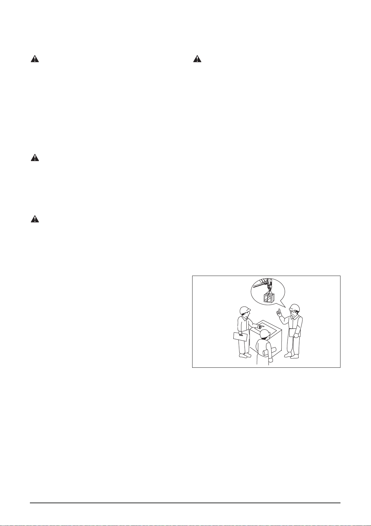
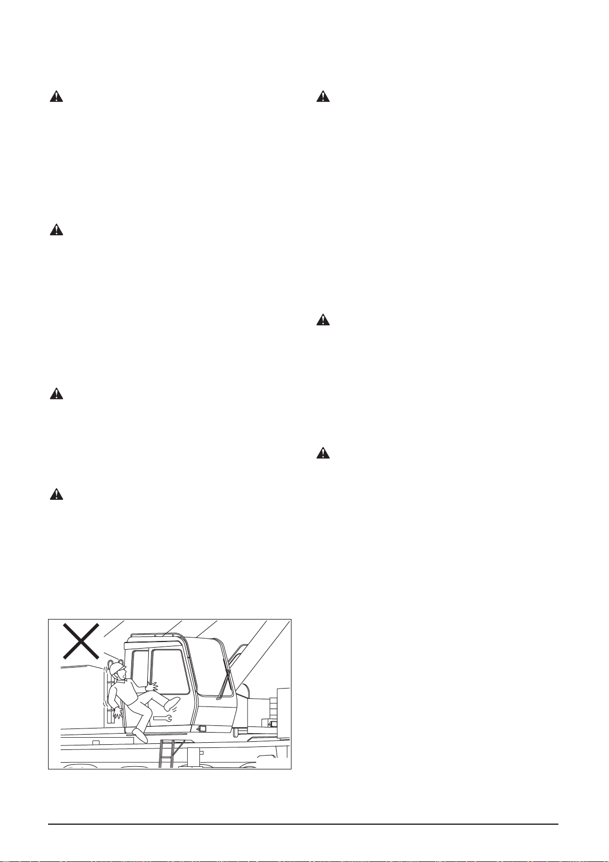
Safely Climbing onto and Descending
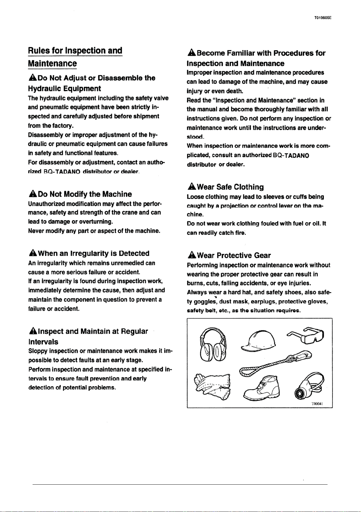
Wear Approved Protective Gear
To ensure safety, always wear a hard hat and safety
shoes. Also protective goggles, dust mask,
earplugs, work gloves, safety belt, etc. must be
worn as the situation requires. Check that all protec-
tive gear is in good condition before wearing it.
T00041
from the Machine
Do not jump onto or off the machine.
Do not climb onto or descend from the machine with
objects in hand.
Only climb onto or descend from the machine while
it is completely at standstill. Use the handrails and
steps, always support your hands and feet firmly
(three point support); that is, one hand-two feet or
two hands-one foot.
Never use the steering wheel or control levers as
handrails.
T03833
Safety Rules Safety Rules
A-3
Page 5
T019605E
T01938E
WARNING
DO NOT OPERATE
Correctly Position the Seat
Incorrect positioning of the operator’s seat can re-
sult in mistakes or fatigue, possibly leading to an
accident.
Before operating the machine, correctly position the
seat so that the pedals and levers can be manipulat-
ed correctly.
Maintain Good Visibility
Fouled window panels, lights or rearview mirrors
can limit the operator’s visibility, impairing safe op-
eration. Always keep the window panels and light
lenses clean.
Position mirrors correctly as required by job condi-
tions.
Perform Pre-Operation Inspection
Neglecting routine inspections and maintenance
can shorten service life of the machine or even re-
sult in an accident.
Before starting operation (and before taking over a
shift), perform the pre-operation inspection on the
carrier and the upper structure to ensure that the
machine is in proper condition and free from any
problems.
Should any problem be found, report it to the re-
sponsible person, remedy it, and only then start
operation.
Do Not Operate a Machine Being
Inspected or Serviced
Operating the machine while it is undergoing in-
spection or maintenance work can cause damage or
an accident.
Post a “DO NOT OPERATE” sign on the operator’s
cab door or any control lever. Do not attempt to op-
erate the machine until the sign is removed by
maintenance personnel.
Check the Position of Controls before
Starting the Engine
If any control lever is in a position other than “neu-
tral”, the machine may initiate some mechanical or
hydraulic function as soon as the engine is turned
over. This situation is very dangerous. Start the en-
gine only when completely sure that all controls are
in the proper neutral or inactive position.
Make Sure Work Area Is Safe before
Starting the Engine
Starting the engine without performing a thorough
safety check of the work area may cause damage to
the machine or injury or death.
Make sure there are no personnel or obstacles un-
derneath or around the machine.
Before starting the engine, sound the horn to warn
any nearby personnel.
Safety Rules Safety Rules
A-4
Page 6

T019605E
T00020
Start the Engine from the Operator’s
Cab Only
If the engine is started from any location other than
the crane operator’s cab, it can become impossible
to avoid a dangerous hazard if some machine action
is initiated when the engine turns over.
Start the engine only from the operator’s seat.
Inspection after Starting the Engine
Failure to perform a basic inspection after starting
the engine can result in not detecting fault or abnor-
mality with the machine.
Inspect the machine in a safe location that is free
from obstacles and people other than maintenance
personnel.
Allow the engine to warm up after it is started while
the instrument readings and checking the machine
components. Once the engine is properly warmed
up, make a safety check of the work area, and run
the machine without a load to check out condition of
the controls, machine elements and safety devices.
Night Operation
Operation in the dark makes it difficult to ensure
good footing, and to locate nearby persons or ob-
stacles, increasing the probability of an accident.
When operating at night, turn on all working lamps.
Provide ancillary portable lighting equipment to illu-
minate the work area.
Keep the Engine Clean
Dead leaves, paper dust and oil stains on and
around the engine can catch fire. Remove all such
debris before commencing operation.
Warm Up the Machine
Failure to properly warm-up the engine and various
other machine components can result in decrease in
service life of the machine or malfunctions. In win-
ter, run the engine for at least five minutes for
proper warm-up.
Then, run the engine at low speed without a load to
warm up the hydraulic oil and other machine com-
ponents.
Keep Unauthorized Personnel Away
from the Work Area
Unauthorized personnel or vehicles in the work area
can result in collision accidents, injury or death.
Before operation, make sure there are no unautho-
rized personnel or obstacles within the work area.
If the work area is situated near heavy traffic, post a
control person to prevent vehicular accidents.
Barricade the work area with appropriate means ei-
ther colored tape or rope.
DANGER
STAY CLEAR
T01937E
Safety Rules Safety Rules
A-5
Page 7
T019605E
T20004
Anticipate Accident Situations
To deal with possible accidents or fires, equip the
crane with a first-aid kit and fire extinguisher. Be
aware of the locations of these safety items, and
learn how to use them properly.
An emergency contact person and emergency liai-
son plan should be carefully prepared, and all
personnel concerned must be made aware of the de-
tails.
Observe Work-site Rules
Neglecting work-site rules can result in accidents.
To ensure safe operation, observe all work-site rules
covering prohibited practices, precautions and cor-
rect procedures.
Post a Signal Person
Assign a signal person for all crane operations as
necessary and always follow instructions especially
when:
• Working near power lines.
• The load is hidden from the crane operator’s view.
• Moving the carrier along narrow roads or when
the operator’s vision is obscured.
The signal person and the operator should commu-
nicate with each other using mobile transceiver
phones.
Hold Work Site Meetings with
Concerned All Personnel
Lack of sufficient communications with concerned
personnel can result in accidents.
Before starting the job, set up a liaison meeting with
the site supervisor, rigging personnel, signal per-
son, etc., to agree on the following details:
• Mass of load, lifting height (per rated lifting capac-
ity table), locations of loading and unloading,
work area of the machine, craning procedures,
rigging methods, etc.
• Conditions of ground where crane is set as well
as whether city-water and gas pipings are buried.
• Overturning prevention by use of block plates and
outriggers.
• Mutually agreed upon and OSHA approved signal
conventions between rigging personnel and sig-
nal person.
• Designation of off-limit areas, provision of barri-
cade.
• Work stations of all relevant workers.
• Emergency liaison plan and emergency contact
person, as well as the safety/health organization.
Safety Rules Safety Rules
A-6
Page 8
T019605E
T20617
Always Study Work-site Conditions
Carefully
Pay due attention to surrounding conditions.
Before starting the job, inspect the work area, check
routes to the work area, and monitor the presence of
any obstacles and locations of other machinery.
Note changes in the surroundings or site conditions
as crane operations are carried out.
Multi-Crane Operation
In lift situations involving the coordination of two or
more cranes, establish an agreed system for com-
munications and assign a signal person. The crane
operators must proceed cautiously, strictly observ-
ing all instructions of the signal person.
Rules for Operation
(Setting Outriggers)
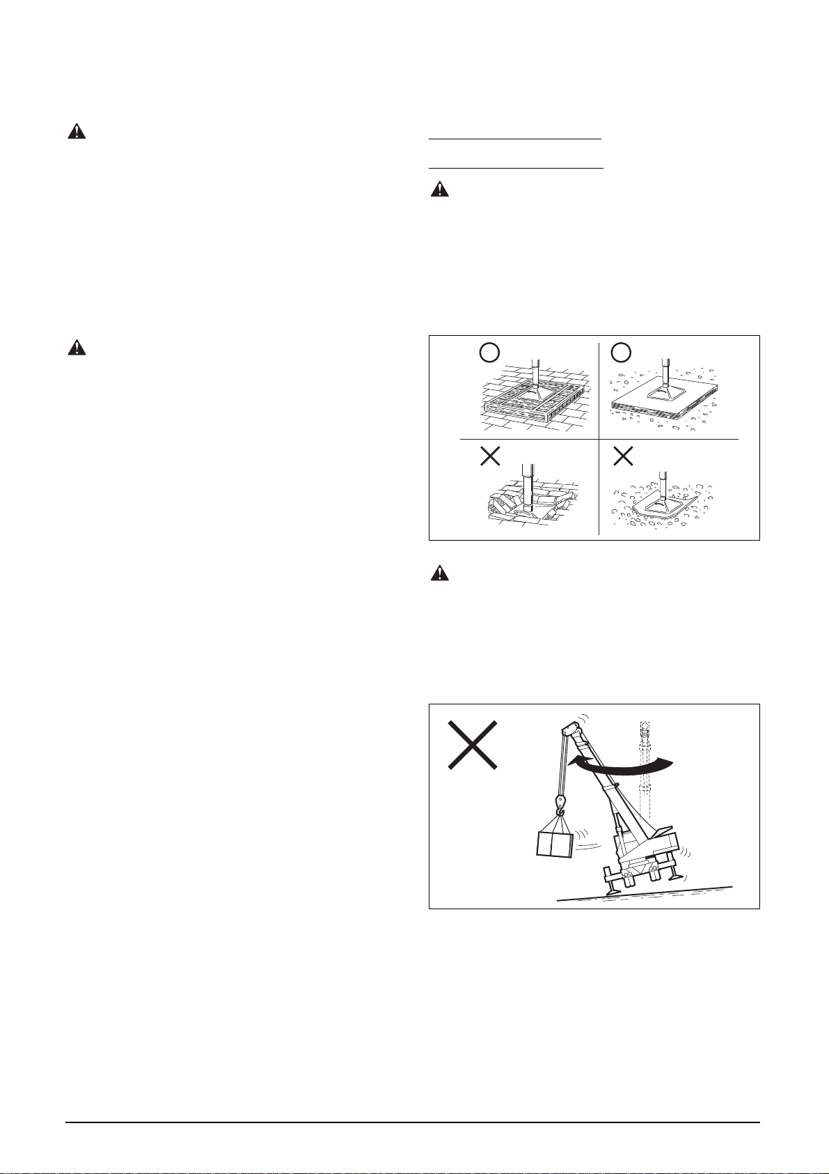
Set the Crane on Firm Level Ground
The machine should not be located on soft ground,
which can lead to sinking, sliding or overturning,
nor on the edge of a pit, bank or slope.
If the ground conditions are doubtful, use blocks or
steel plates of sufficient strength and size below the
outrigger floats to disperse the load.
Set the Crane Level
If the crane is tilted, and the load is swung over the
side, the load radius will increase, and the machine
can overturn.
When setting the outriggers, level the machine care-
fully using a level.
T00008
Safety Rules Safety Rules
A-7
Page 9

T019605E
T01939E
Fully extended
Fully Extend the Outriggers
If the outriggers are not extended correctly, the
crane may become unstable, causing the crane to
overturn.
As a general rule, always extend the outriggers fully,
even if the crane is rated for operation with the out-
riggers at middle or minimum extension. If it is
absolutely necessary to use the outriggers at middle
or minimum extension, make sure the machine is
within the rated limits.
Rules for Operation (General)
Observe Working Conditions
Operating the crane under conditions (outrigger
beam length, boom length, load radius, etc.) other
than specified in the rated lifting capacity table can
cause overturn even when not lifting a load.
Follow all instructions in the rated lifting capacity
table.
Do not Exceed Rated Lifting Capacity
Exceeding the rated lifting capacity will overload the
machine. Damage or overturning can result from
this practice.
Check the rated lifting capacity table before operat-
ing to ensure that the lift is safe. Load lifting
capacity of the crane varies depending on boom
length and load radius. Never exceed the lifting ca-
pacity in the table.
Check the Outrigger Setting
Incorrect setting of the outriggers can decrease the
load lifting capacity of the machine and result in
overturning. To avoid crane instability, make sure:
• The machine is absolutely level.
• All outrigger floats are stable and set firmly on the
ground or blocks.
• All tires are clear of the ground.
• The outriggers are secured with lock pins (if lock
pins are available).
Mass of hook block
Rated lifting capacity
Lifting capacity
T21566E
Use Safety Devices Correctly
Improper use of safety devices including the over-
load cutout can lead to damage or overturn the
crane.
Use all safety devices according to instructions in
the manual.
Safety Rules Safety Rules
A-8
Page 10
T019605E
T03802E
Boom deflects
Load radius
Do Not Rely Exclusively on Safety
Devices
A safety device is not a substitute for human skill
and judgment.
The overload cutout, for example, does not warn the
operator about conditions on the ground, effects of
wind, improperly adjusted devices, load being
pulled sideways, or other possibly hazardous situa-
tions.
All safety devices are merely auxiliary means to help
the operator perform the task at hand. Safe crane
work requires the qualities of a good operator, such
as skill, experience, judgment, and safety aware-
ness.
Do Not Deactivate Any Safety Devices
Avoid any action that impairs normal operation of
the safety devices.
Intentionally deactivating any safety device may re-
sult in the inability to detect overloading or
overwinding during operation, and lead to a serious
accident.
Ensure that all safety devices are functioning cor-
rectly before starting any operation.
Rig the Load Securely
Improper rigging procedure can result in the lifted
load being dropped. Rig the load securely, paying
special attention to the following points:
• Know the mass, shape and center of gravity of the
load, and use suitable load handling devices and
rigging hardware.
• The load handling devices including wire ropes,
chains and rigging hardware must have enough
strength and be free from damage or excessive
wear.
• Rig the load so that it is suspended at a point
above its center of gravity. Otherwise, the load
can overturn or come loose of the handling device
when it is raised. Also, wire ropes and chains
must not be crossed or twisted around each oth-
er.
• Do not rig the load with a single wire rope. Such
rigging practice is very dangerous as the load can
rotate, and untwist the wire rope, reducing its
strength.
• When rigging a load with sharp corners, fit protec-
tive softeners at the load corners to protect the
wire ropes and the load itself against damage.
Before Lifting a Load
Make sure of the following before attempting to pick
up a load:
• The mass does not exceed the rated lifting capaci-
ty.
• The number of rope parts conforms to the stan-
dard in the rated lifting capacity table.
• A proper load handling device is used and the
load is securely rigged.
• The hook block is located directly above the cen-
ter of gravity of the load.
• The wire ropes runs are plumb so that the load
can be lifted vertically.
• The safety latch on the hook is working properly.
• The wire rope has no entanglement or disorderly
winding on the drum.
Consider Boom Deflection before Lifting
the Load
When a load is lifted, the boom will deflect down-
ward, increasing the load radius. Swaying of the
load also poses a hazard to the people around the
crane, and may lead to overloading.
If the load starts to sway when lifted clear of the
ground, lower the load back on the ground.
When lifting a heavy load or using the extended
boom, anticipate the possible increase in the boom
load radius.
Safety Rules Safety Rules
A-9
Page 11
T019605E
T00011
Lift Single Loads Only
Do not lift two or more loads simultaneously even if
their total mass is within the specified rated lifting
capacity; otherwise, the loads may lose balance. It
is usually not possible to maintain complete atten-
tion to multiple loads.
Operate According to Signals
If signals are not obeyed or if signals are improperly
made, accidents can occur.
Follow instructions of the signal person. An emer-
gency shut down signal must be acknowledged
whoever gives it.
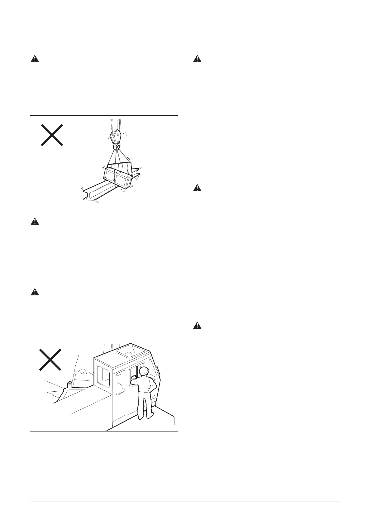
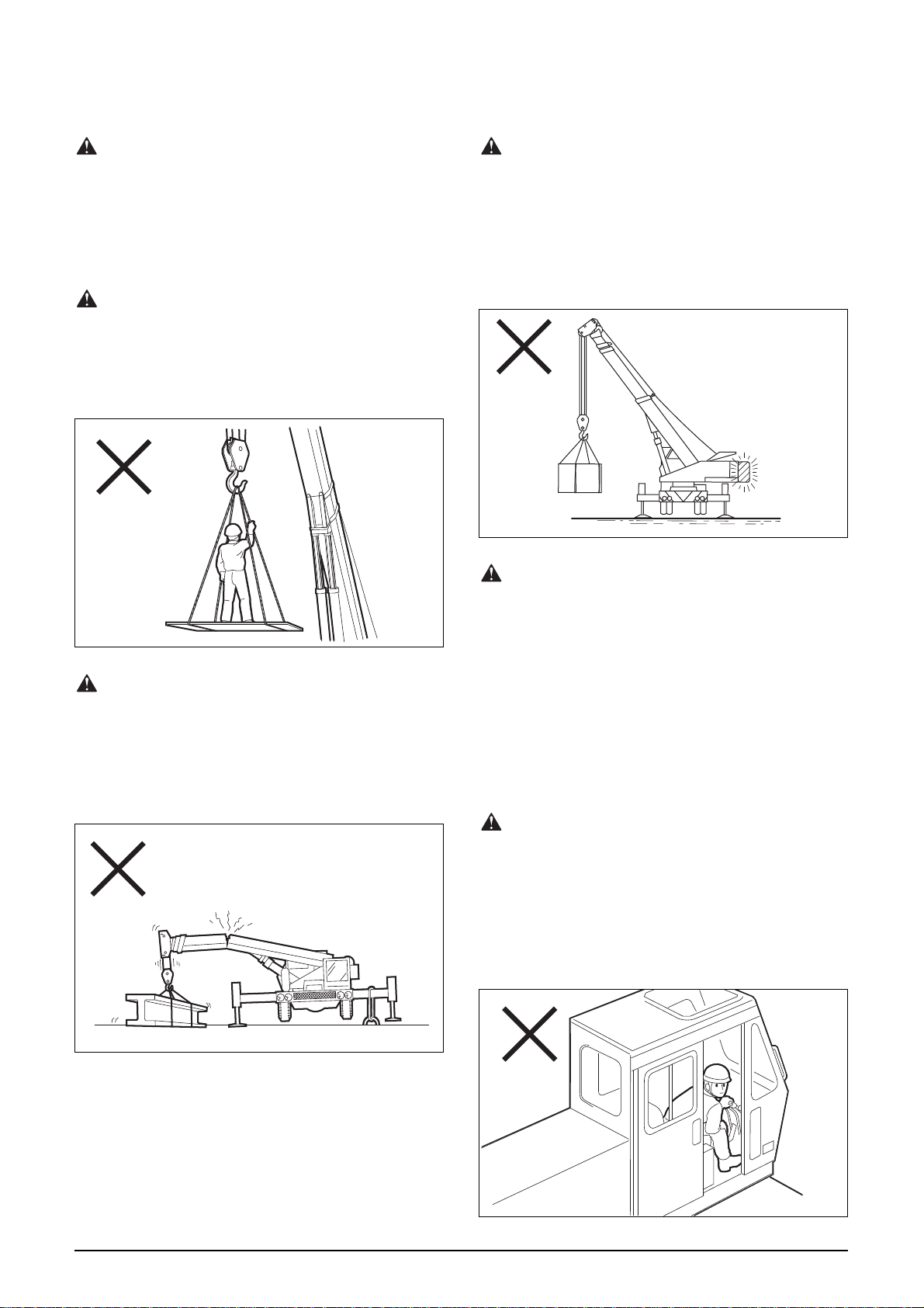
Operate the Crane from the Operator’s
Conduct a Safety Check within the Load
Radius of the Crane before Starting
Operation
Any person located close to the crane may become
caught between machine components or between
the counterweight and a fixed obstacle. Before
starting any swing motion, make sure that there is
no one nearby. Sound the horn to warn all immedi-
ate personnel of crane startup.
During crane operations, fence off or barricade the
work area to prevent unauthorized persons from ap-
proaching the machine.
Be Extremely Careful When Raising the
Load Clear of the Ground
Stop lifting the load once the rigging is fully taut,
check that the load is suspended at a point just
above its center of gravity, and that the load is not
stuck to the ground or interfering with a nearby
body or structure.
Lift the load vertically. When the load clears the
ground, stop lifting and suppress any swaying; then
check that the rigging is secure, the load is in a sta-
ble position, and the crane is not overloaded.
Then, recommence the lift again.
Cab Only
Controlling the machine from outside the cab,
through the cab window, is strictly forbidden and
extremely dangerous.
T00019
Do Not Lift the Load Clear of the Ground
by Raising or Extending the Boom
Raise a load clear of the ground by vertical hoisting
only.
Raising or extending the boom to lift a load clear of
the ground will cause the load to sway, posing a
hazard.
If the boom is elevated to raise a load clear of the
ground, the crane will not be automatically stopped
even in case of an overload. An overloaded machine
can overturn or be damaged.
Safety Rules Safety Rules
A-10
Page 12
T019605E
T01941
Move a Lifted Load Carefully
When the crane state comes near the full rating, the
AML gives an intermittent alarm. Operate the crane
more carefully and slow the load-moving speed.
Take best care for over-loading in boom-lowering
operation which enlarges the load radius.
Do Not Lift an Unknown Load
Attempting to uproot a garden tree or raise an object
buried or driven into the ground can severely over-
load various components of the machine, possibly
causing the machine to overturn or be damaged. Do
not attempt to pull up poles or piles driven into the
ground, trees or any objects buried or frozen in mud
or sand.
Only lift objects free from all restraining forces.
Operate the Crane Carefully
Operating the controls too abruptly can result in an
accident: a swaying load can hit an object or dam-
age the machine.
Operate all control levers and pedals smoothly and
in a steady manner.
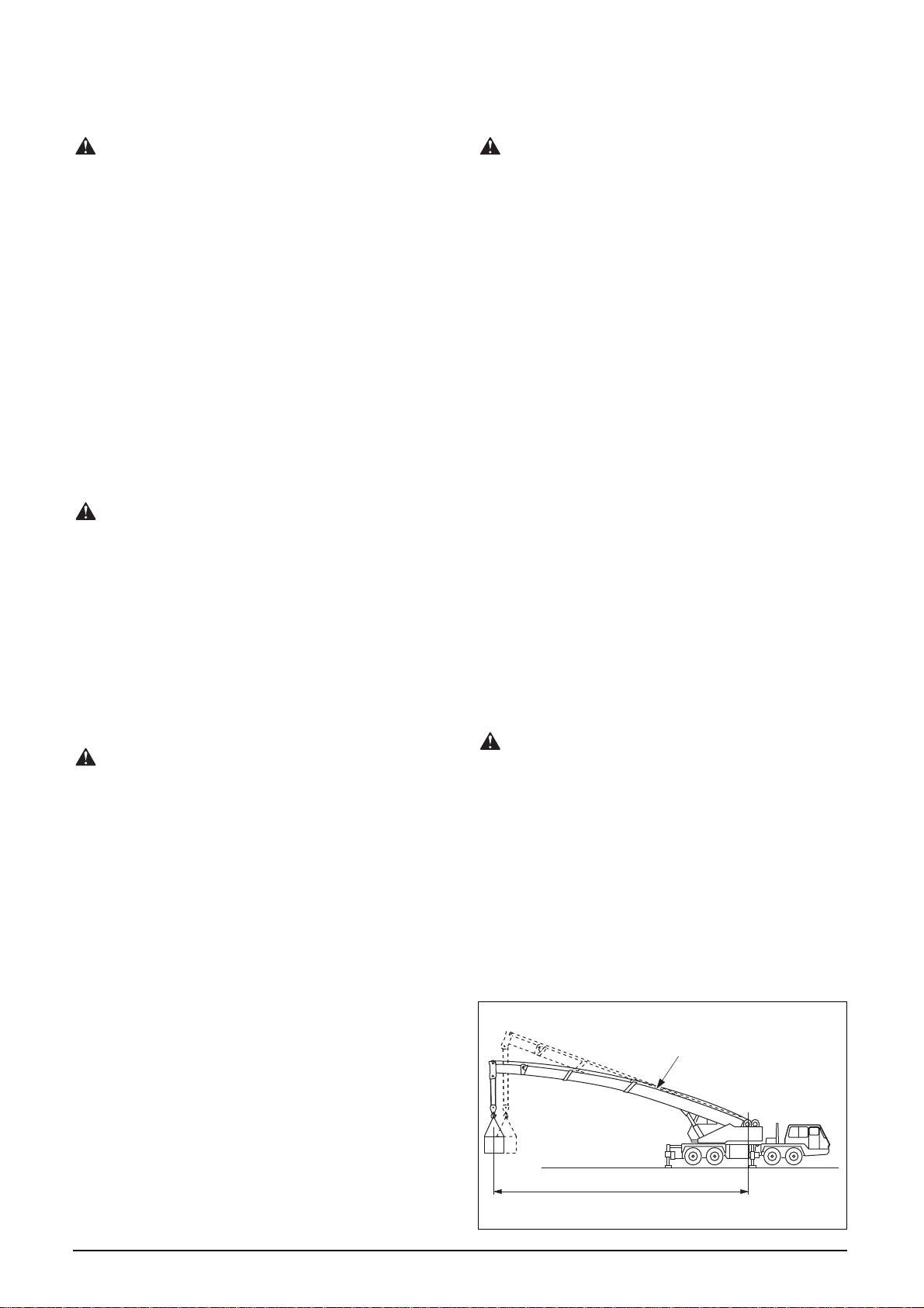
Do Not Make Inadvertent Swing
When the front jack is not employed, lifting capaci-
ties in the over-front area are inferior to those in the
over-rear and over-side areas. The crane may be
overturned if inadvertently swung to the over-front
area with a load lifted in the rear or side area.
Depending on boom length, boom angle, and outrig-
ger extension, even the unloaded crane may
overturn because of inadvertent swing.
Before operation, confirm the living capacity by the
rated lifting capacity table. If there is an inferior ca-
pacity area, place signal corns or ropes for swing
restriction to avoid swing into such a perilous area.
Avoid Overloading
A load below the rated lifting capacity can still
cause overloading of the crane if swaying occurs.
Do not trigger overloading while telescoping out or
lowering the boom. These actions increase the load
radius and are destabilizing.
When Overloading Occurs
When overloading occurs, never attempt to raise or
lower the boom rapidly. This situation is very dan-
gerous as the machine can readily overturn.
Immediately set the load on the ground by carefully
unwinding the wire rope off the winch drum.
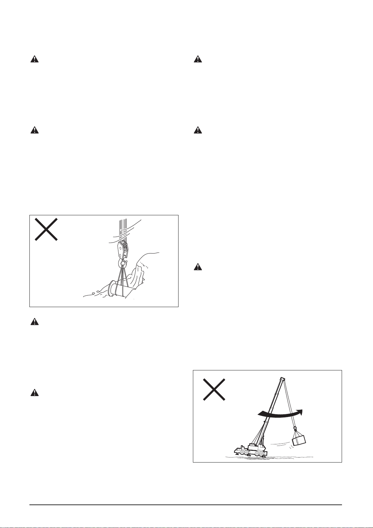
Swing the Crane Carefully
If the swing speed is too high, substantial centrifu-
gal force is applied to a load, resulting in an
increased load radius. As a result, the machine may
become overloaded and overturn.
Stopping a swing operation abruptly can cause a
load to sway posing a hazard to nearby personnel
and possibly leading to boom failure.
Swing all loads slowly. Carefully stop any swinging.
Be extremely cautious when working with an ex-
tended boom.
T00029
Safety Rules Safety Rules
A-11
Page 13

T019605E
T02212
Be Careful during Complex Operations
Actions of the crane will be slower during complex
operations. When switching from a complex opera-
tion to a simple operation, action of the machine will
become faster. When executing a complex opera-
tion, do not change speed immediately.
Do not attempt any complex operation until fully fa-
miliar with the crane operation.
Avoid Contact with Obstacles
While moving a load, be absolutely sure that the
load or any part of the crane does not come into
contact with nearby structures or other objects.
When working on a site where potential obstacles
are present, post a signal person, and only move the
load while following instructions.
Be Careful When the Boom Is at
Maximum Permissible Angle
When the boom is raised to its maximum permissi-
ble angle, there exists minimum horizontal
clearance between the boom and the load. A sway-
ing load may hit the boom or jib, and cause damage.
Handle the load carefully so that it does not strike
the boom or jib.
Be Careful in Demolition Work
It is very dangerous to lift parts or components of a
structure undergoing demolition, if the mass and
center of gravity are unknown. Before starting oper-
ation, ascertain the mass and center of gravity of the
loads, and establish the lift procedure to be taken.
Operate the Crane with Correct Boom
Position
When the boom configuration is irregular for pur-
pose of inspection or maintenance, never attempt to
lift a load.
During crane operation, check that all the boom sec-
tions are telescoping in the correct sequence. The
rated lifting capacity table has been developed
based on assumption that the boom sections are
telescoped in the correct sequence.
Do Not Extend the Boom Excessively
An excessively extended boom decreases the rated
lifting capacity and also can cause overswing of the
load or lower working efficiency.
Keep the length of the boom as short as possible
during operation.
T01944
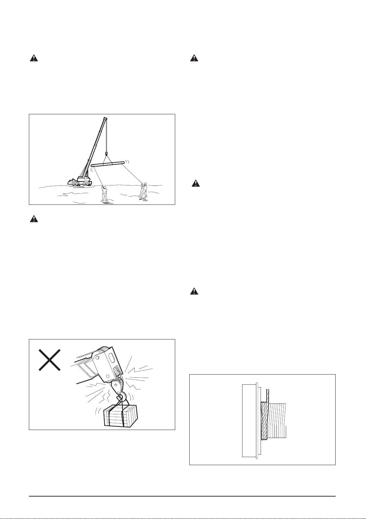
Carefully Lift a Load in Water
When handling a load submerged in water, it is im-
portant not to lift the load out “all at once” when it
appears above the water’s surface. The load may be
impregnated with water and heavier than expected.
Allow the load to drain while raising it slowly.
A load lifted out of water, even when fully drained,
weighs more than it did when submerged because
of buoyancy effects. Lift the load carefully so as not
to cause overloading.
Safety Rules Safety Rules
A-12
Page 14
T019605E
T00028
Handle Wide Loads Carefully
Be careful when lifting a wide load. The load can
swing and hit a rigging person, the crane itself or a
nearby structure.
Use tethers tied to either or both ends of the load to
control the position and/or movement of the load.
Do Not Overwind the Hook Block
When the boom is lowered or extended, the hook
block is wound up.
Usually, overwinding the hook block will cause the
overwind cutout device to trip and the winch auto-
matically stops. However, if the device is damaged
or the automatic stop function has been deactivated
for some reason, the hook block can impact the
boom head.
Always be aware of the position of the hook block. If
the hook block approaches the boom head, wind off
the wire rope to lower the hook block and avoid con-
tact.
Know of the Number of Wire Rope Parts
If the number of the part lines is greater than speci-
fied for the boom length, the hoist line may become
too short. As a result, the line can unwind off the
winch drum causing the wire rope to be damaged or
broken.
When lowering a very light load, or a bare hook
block, the rope will unwind off the winch drum at a
faster rate. The rope may then become improperly
wound.
Use a number of part lines appropriate to the boom
length.
Wire Rope Must Be Properly Wound on
the Drum
Lifting a load with the wire rope improperly wound
on the winch drum can lead to damage of the wire
rope, not only decreasing service life of the rope but
possibly breaking wires and strands which can lead
to ultimate failure.
After reeving or replacement of the wire rope, make
sure that the line is properly seated in the sheaves
and on the winch drum.
Do Not Unwind the Wire Rope
If the entire rope is unwound from the winch drum,
the frictional anchoring force will be insufficient to
support a load. The rope will break or become dam-
aged.
At least three winds of rope must always be left on
the winch drum. This condition applies particularly
when a load must be lowered below ground level
such as a trench or excavation.
T00026
T00024
Safety Rules Safety Rules
A-13
Page 15
T019605E
T00015
Do Not Leave a Load Suspended
Do not leave a load in a hoisted position. Actuate
the winch brake to hold the load safely. Use working
procedures that minimize the duration a load is left
suspended.
Use the Crane Only for Approved
Applications
The crane is designed to lift a freely suspended ver-
tical load. Never attempt to lift persons, or push/pull
a load with the boom.
Do Not Add Counterweights
Installing a counterweight(s) other than those speci-
fied can damage the machine, or cause the machine
to overturn to the rear owing to decreased rearward
stability.
Never install or place a counterweight(s) or equiva-
lent other than those specified.
T03804
Do Not Position Any Part of Your Body
Do Not Anchor the Machine
Do not attempt to hold down the crane frame or out-
rigger or contrary side to the lifted load, using wire
rope.
This practice might lead to crane damage or an acci-
dents.
T00002
Out of the Window on the Boom Side
Sticking any part of your body out from the window
on the boom side can result in being caught be-
tween the moving boom and the window frame.
Serious injury or death can result from this danger-
ous practice.
If the window is equipped with a confining guard, do
not remove it.
Do Not Look Away from the Load While
Operating the Crane
Looking away from the load, eating or performing
any other action that can detract from awareness
while operating the crane is very dangerous.
During operation, concentrate all attention on the
load and the signal person.
T00018
Safety Rules Safety Rules
A-14
Page 16

T019605E
T00027
Do Not Pass a Load over Any Person
Passing a load over a person(s) is very dangerous
and must be avoided.
Do not allow anyone to enter the area below the
boom or the load.
Do Not Pull a Load Sideways, Do Not Lift
a Load Obliquely, Do not Drag a Load
Pulling a load sideways, lifting a load obliquely or
attempting to drag a load is very dangerous. Such
actions can damage the boom, jib or swing mecha-
nism, and lead to overturning of the crane.
Do not attempt to draw in a load that is located out-
side the load radius. To handle such a load, move
the crane to the vicinity of the load, and lift it verti-
cally.
Do Not Leave the Operator’s Cab While a
Load Is Suspended
Before leaving the operator’s cab for any reason, be
sure to:
• Lower the load to the ground.
• Fully retract the boom and stow it.
• Actuate all brakes.
• Place all control levers in their neutral positions.
• Shut off the engine, and remove the starter key.
• Lock the crane operator’s cab door.
Never Allow Anyone to Ride on the
Machine, Except the Operator
If any persons other than the operator (in the opera-
tor’s seat) are on the machine, they must be
stationed inside the operator’s cab.
Do Not Allow Anyone to Ride on the
Machine
Persons on the machine other than the operator (in
the operator’s seat) may fall or be caught by a ma-
chine component or other objects. Other persons
cause distraction and can disturb the attention and
work of the operator.
T00017
Do Not Push or Pull an Object with the
Boom
Never use the boom to push or pull an object. Do
not use the boom to thrust up an object or force the
boom into an object.
To move an object, use a machine designed for that
purpose, such as a fork lift truck or carryall.
Do not use the crane in applications other than
those specified.
T00016
Safety Rules Safety Rules
A-15
Page 17

T019605E
T20527
Caution while Using the Jib (1)
Never attempt to lift separate loads on both the
boom and jib at the same time, or a single load us-
ing both the main and auxiliary winches.
Such practices can damage the boom or jib, or over-
turn the machine.
Caution while Using the Jib (2)
Lifting a load on the boom with the jib mounted
should be avoided, if possible.
If conditions require such a lift, observe the instruc-
tions given in the “AML” section of the manual and
perform the operation with the utmost care and at-
tention.
Mount and Stow the Jib Correctly
Failure to observe the specified procedures for
mounting and stowing the jib can damage the jib, or
may cause the jib to drop.
Be sure to mount and stow the jib in the correct
manner by referring to the “Jib” section in the man-
ual.
T00649
T00013
Safety Rules Safety Rules
A-16
Page 18
Rules for Operation (Weather)
Stop Operation When Visibility Becomes
Poor
During bad weather such as rain, snow or fog, stop
operation and stow the machine. Wait until visibility
improves before resuming operation.
T019605E
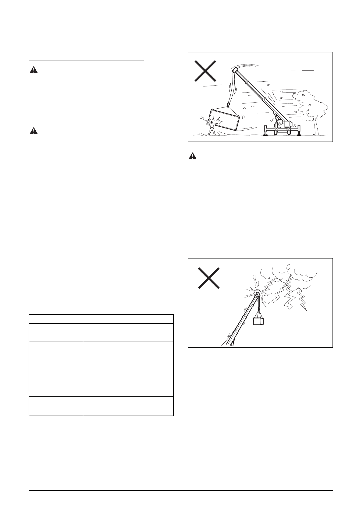
Stop Operation When Strong Winds are
Present
Under strong winds, a lifted load will start swaying,
posing a danger to working personnel and nearby
structures and also possibly damaging the boom or
overturning the machine.
The influence of cross wind on machine stability is
directly proportional to length of the boom and size
of the load.
When the maximum instantaneous (i.e. gust) wind
speed exceeds 10 m/sec, stop crane operation and
stow the boom.
When the boom is substantially extended or a large-
sized load is lifted, stop crane operation even if the
wind speed is below 10 m/sec if there is any possi-
ble danger.
The table below lists wind speed ranges and the
ground conditions for each range. Note that the
wind speeds in the table are those at a point 10 m
above open level ground.
T00037
Stop All Operation If There is Any
Likelihood of Lightning
Lightning can not only damage the machine but also
injure the operator and working personnel. If light-
ning is forecast or expected, stop operation, stow
the boom, and leave the machine.
If the machine is struck by lightning:
• Stay in the cab. Do not try to move out.
• Warn people around not to approach the machine.
• Afterward, inspect the entire crane carefully and
have any damaged parts repaired.
Wind speed (m/sec) Ground conditions
5.5– 8.0
8.0–10.8
10.8–13.9
13.9–17.2
Safety Rules Safety Rules
Dust is raised, paper whirls up,
and small branches sway.
Shrubs with leaves start swaying.
Wave crests are apparent in
ponds or swamps.
Tree branches move. Power lines
whistle. It is difficult to open an
umbrella.
Whole trees sway. It is difficult to
walk against the wind.
T00038
A-17
Page 19

T019605E
Cautions in Cold Weather
• Snow or ice on the crane should be removed be-
fore operation; it is especially important to
eliminate any accumulation on the boom, as it
could fall and injure someone when the boom is
moved.
• Do not let bare skin come in contact with the ma-
chine’s metallic parts when the temperature is
below freezing. Skin can freeze to the metallic sur-
face, if any moisture is present.
• Warm up the machine sufficiently. Then, check
that the machine is functioning correctly. Remove
ice and dry machine components as required.
• After starting operation, run the machine slowly
until oils fully circulates through all machine com-
ponents.
• Before lifting, make sure that the load is not
frozen to the ground or any other objects.
Attempting to lift a load which is frozen to the
ground can result in severe overloading and is
very dangerous.
• If possible, stow the machine indoors so that the
tires are not frozen to the ground. Remove mud
from the undercarriage.
• Maintain the battery. Use oils and fuel rated for
cold weather.
Rules for Operation
(Power Lines, Radio Waves)
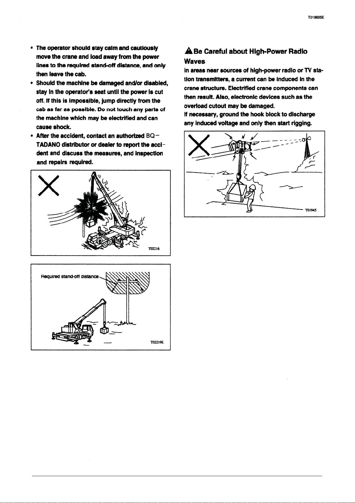
Prevent Electric Shock Accidents
Approaching too close to power lines can result in
electric shock accidents. If conditions absolutely re-
quire operation near power lines or distribution
lines, implement the following preventive measures:
• Meet with the power company concerned to devel-
op a relevant safety plan.
• Require that working personnel wear approved
insulating shoes.
• Keep the crane and load beyond the required dis-
tance (stipulated by national or local laws and
regulations) and away from power lines.
• Post a full-time signal person to ensure the ma-
chine or load does not approach power lines or
unauthorized personnel do not enter the work
area.
• Personnel on the ground must not directly touch
the machine or load. When necessary to control
the lifted load, use dry fiber ropes as tethers to
prevent the load from rotating or swaying.
• Do not place a load below or near power lines.
• Operate the crane slowly with the utmost care and
attention.
(The data shown below describes the required dis-
tance recommended by Japanese power
companies.)
Voltage Required stand-off distance
Low voltage 100 V, 200 V
High voltage 6,600 V
22,000 V 3 meters
66,000 V 4 meters
Extra high 154,000 V 5 meters
voltage 187,000 V 6 meters
275,000 V 7 meters
500,000 V 11 meters
Should an electric shock accident occur, do not
panic. Follow the instructions below:
• Contact the power company to cut off the power
and obtain instructions for emergency action.
• Direct all personnel around the machine to evacu-
ate the site. Strictly control the site and keep
everyone away from the electrified crane and load.
Safety Rules Safety Rules
A-18
2 meters
Page 20
Safety Rules Safety Rules
A-19
Page 21
T019605E
T00650
Rules for Operation
(Special Operation)
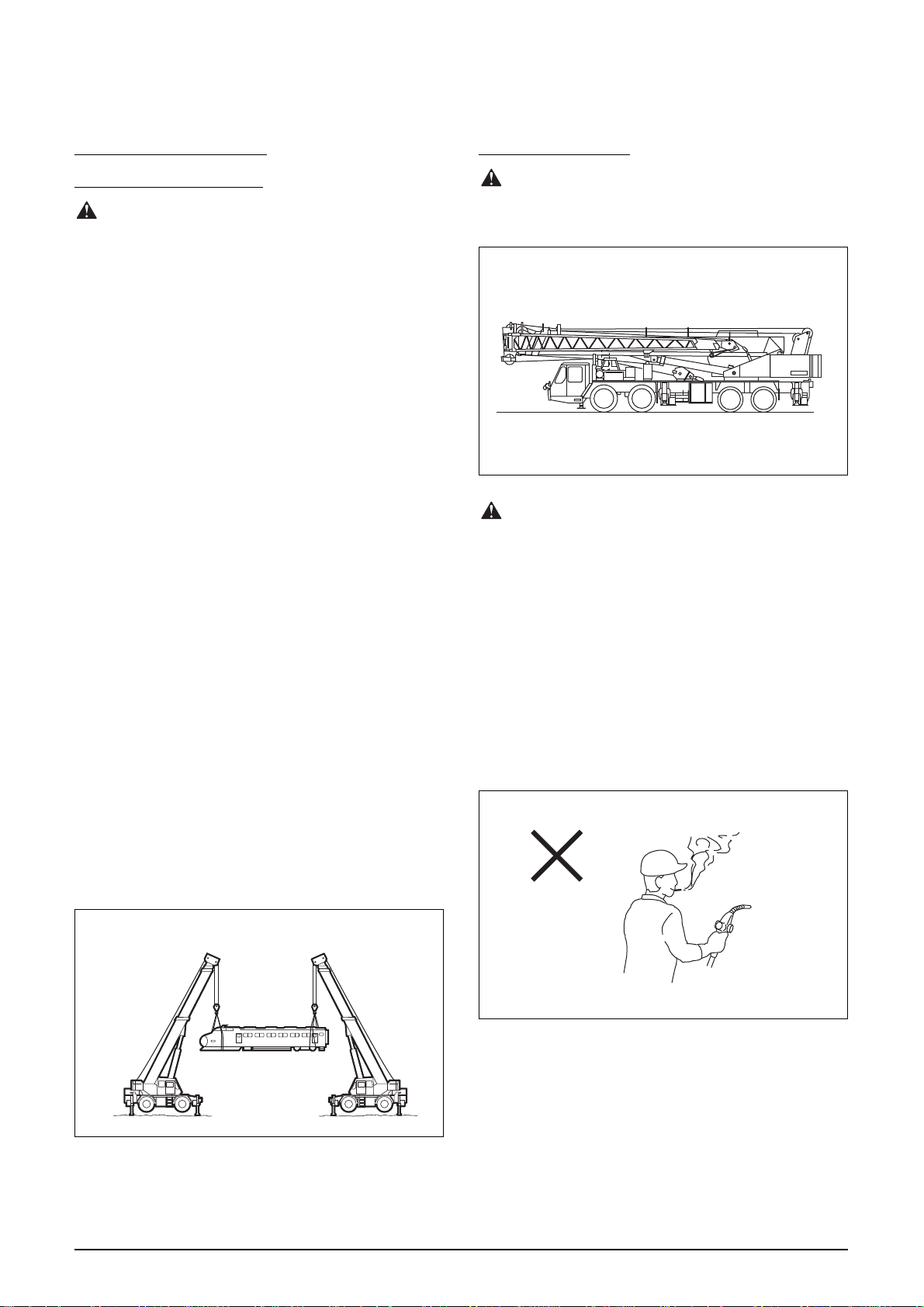
Be Cautious in Multi-Crane Operation
Lifting a load with two or more cranes can be dan-
gerous. In these operations, loads are lifted at
points other than directly above the center of gravity
and there is possibility of the load falling, the ma-
chine being overturned, or the boom failing.
In multi-crane lifting operations, be absolutely care-
ful, and adhere to the following instructions:
• Meet with personnel to determine the proper
working procedure and lift strategy.
• Assign a work leader, and follow instructions.
• Equip every person concerned with an appropri-
ate communications device.
• Set each crane level on firm ground with the out-
riggers fully extended.
• The cranes used must have the same perfor-
mance, characteristics and sufficient capacity for
handling the load. Make sure that the cranes have
the same settings for the boom length, boom an-
gle, and number of rope parts.
• Lift the load so that the wire rope(s) of each crane
are only subjected to vertical line pulls.
• Attempt to rig the load so that all the cranes are
loaded equally.
• To move the load, use only the winches and
booms. Swinging operations should be avoided.
Do not perform hoisting, elevating (or telescop-
ing) of the boom or swinging at the same time.
• To prevent overloading, operate the separate
cranes simultaneously.
After Operation
After Operation, Stow the Machine
Leaving the machine unattended should be avoided.
Once operation is complete, stow the machine.
T21496
Cautions for Refilling the Fuel
Fuel and other oils are highly flammable and dan-
gerous.
Handle combustibles very carefully.
While refueling, observe the following instructions:
• Stop the engine.
• Refuel the machine outdoors in a well-ventilated
place.
• Keep sources of flames or sparks away from the
fuel.
• Wear a protective mask.
• Do not refuel in excess of fuel tank capacity.
A00195
Safety Rules Safety Rules
A-20
Page 22
T019605E
T21496
Rules for Road Travel
Observe All Vehicles Code
Requirements for Travel on Public Roads
Some national and local laws and rules exist regard-
ing the travel of crane vehicles on public roads.
Before traveling on roads, study the requirements
for road travel for the crane, and strictly obey all the
regulations.
Driving Crane (Carrier) in Road Travel
Configuration
A swaying hook block or boom, or extended outrig-
gers pose extreme hazards during crane road travel.
Before traveling, stow the hook block and boom in
position, and lock the outrigger beams, etc., in posi-
tion (if lock pins are available). Give a traveling
configuration to the machine by referring to the
manual.
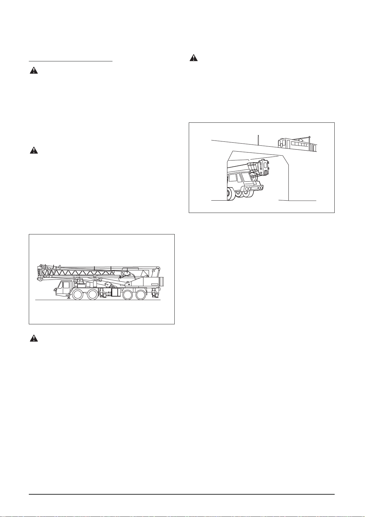
Be Aware of Overhead Obstacles
Pay attention to overhead clearance when passing
under electric car wires, highway or railway bridges,
and passing through a tunnel.
If the planned route necessitates travel below over-
head railway lines or overhead bridges or through a
tunnel, check the clearances in advance.
T21495
Do Not Travel with Any Cargo on the
Crane
Carrying cargo on a traveling crane can result in a
spill or fall. Use a vehicle designed specifically for
cargo transport.
Safety Rules Safety Rules
A-21
Page 23
Safety Rules Safety Rules
A-22
Page 24
T019605E
T01951
Meet with Working Personnel
Working together with other persons on inspection
or maintenance tasks without observing mutually
agreed upon procedures can result in an accident.
Meet with all involved personnel to agree on the de-
tailed tasks. Also, assign a work leader, and always
follow his or her instructions.
Provide Effective Ventilation
Performing inspection or maintenance work in a
confined space without effective ventilation can lead
to toxic poisoning.
Be very careful when handling fuel, wash oil, and
paint.
When starting the engine in an enclosed space, pro-
vide a means of positive ventilation. Connect a hose
from the exhaust to vent the fumes outdoors. Open
doors and windows to allow fresh air circulation.
Install a ventilator as required.
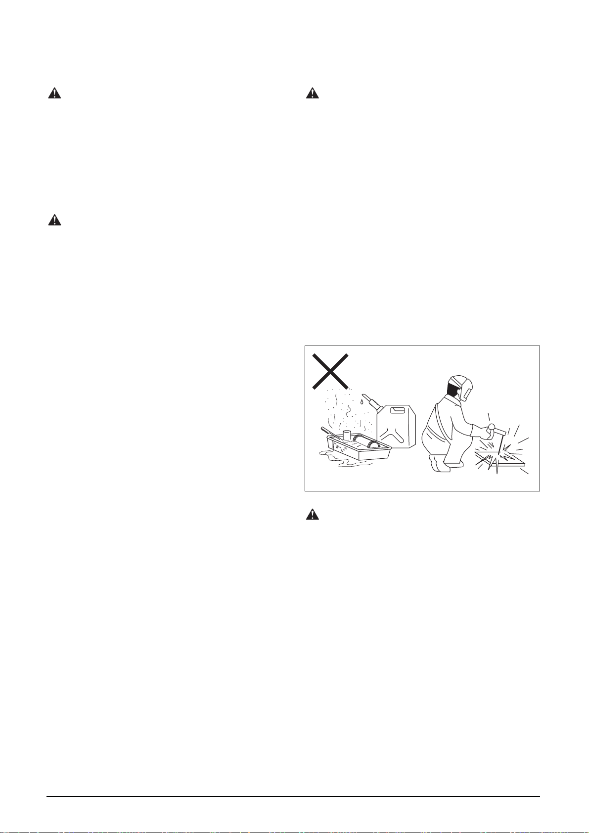
Fire Prevention
To prevent the risk of fire during inspection and
maintenance work requiring handling of potentially
flammable substances, observe the following in-
structions.
• Use a non-flammable cleaning liquid to wash
parts and components.
• Store fuel and oils away from fire.
• Do not allow sources of flames or sparks near any
substance that is combustible.
• Do not smoke cigar or cigarette.
• Always carry a fire extinguisher in the operator’s
cab.
• When checking fuel, oils, and battery liquid, use
an explosion-proof lamp.
• When grinding or welding, keep flammable sub-
stances away from flying sparks or molten metal.
About Illumination
Inspection or maintenance work in a poorly illumi-
nated environment can lead to injury. Before
starting the work, provide proper illumination.
Never use the exposed flame of a match or lighter
for illumination, a fire accident may occur. The emit-
ted gas from open lead storage batteries can
explode.
Use explosion-preventive type illuminating devices
when checking fuel and battery liquid level.
Safety Rules Safety Rules
A-23
Page 25

T019605E
Clean the Machine before Inspection
or Maintenance
Dirt and debris on the machine not only prevents
easy detection of faulty components or parts but
also can be trapped in components or parts. Also,
dust or mud can enter your eyes or cause you to
slip and be injured.
Before starting general inspection or maintenance
activities, wash the machine to ensure a safe work
area.
Cautions for Washing the Machine
Wet footing can cause to slip and fall injuries.
Always wear non-slip shoes.
When washing the machine with high-pressure
steam, the jet can penetrate skin or flying mud can
cause eye damage. Always wear suitable protective
gear during washing.
Do not direct water to electrical equipment, dis-
charge and/or shortcircuits can result and lead to
damage.
Labeling for Inspection or
Maintenance Work
If any unauthorized person starts the engine during
inspection or maintenance work, the machine may
be damaged or injury or even death may result.
When performing inspection or maintenance work,
remove the starter key, and post a “DO NOT OPER-
ATE” or “TAG OUT” sign on the door or control
levers of the operator’s cab as a warning.
Also, post relevant warning signs at entry to the
work area to prevent access of unauthorized per-
sonnel.
Start Inspection or Maintenance after
the Machine Has Cooled Down
When the crane is operated, various machine com-
ponents become very hot and can cause burns.
These components include the engine, muffler, en-
gine cooling water, radiator, hydraulic oil, reducer,
hydraulic equipment and hydraulic piping.
Allow these components and areas to cool down be-
fore starting inspection or maintenance work.
Inspect and Maintain the Machine on
Level Ground
It is difficult to inspect the machine properly if it is
parked on a slope or grade. Also, the machine is li-
able to start moving if not parked properly.
Park the crane on firm flat ground, activate the park-
ing brake, and chock the tires.
Keep the Work Area Clean and Tidy
Performing inspection or maintenance work in a dis-
orderly place can lead to personal injury or a falling
accident.
Remove obstacles.
Beware of High-Pressure Oils
High-pressure fuel or hydraulic oil that comes into
contact with skin or eyes can cause serious injury.
To avoid this danger:
• Release internal pressure, and only then, discon-
nect any piping.
• To check for leakage, wear protective goggles and
gloves and use a piece of cardboard or wood as a
monitor. Leaking high-pressure oil may be invisi-
ble.
Keep bare hands away from all leaking compo-
nents.
• Immediately obtain medical attention when high-
pressure oil accidentally cuts into skin or affects
the eyes.
Safety Rules Safety Rules
A-24
Page 26
T019605E
T03835
Inspect or Maintain Equipment with
the Engine Shut Down
Performing inspection or maintenance work while
the engine is running is very dangerous, and should
be avoided. Unless otherwise necessary, be sure to
shut down the engine before starting inspection or
maintenance procedures.
Use Two Persons for Inspection or
Maintenance with the Engine Running
If for some reason it is necessary to perform an in-
spection or maintenance procedure with the engine
running, post at least two persons—one in the oper-
ator’s cab to shut down the engine immediately
when necessary, and the other(s) to perform mainte-
nance. During the maintenance, ensure safety of all
persons involved in the work.
Use Proper Tools
Performing inspection or maintenance work without
the proper tools not only decreases work efficiency
but also can lead to damage to parts or even injury.
Do not use improper or damaged tools.
Beware of Overhead Obstacles and
Footing
Lack of awareness or loose footing can cause head
impact with the hook block, boom, or jib or slip and
falls off the machine.
Always be careful about overhead obstacles and
footing. Walk on the non-slip strips if provided on
the machine.
Cautions for Working at Heights
Working at heights involves the possibility of falling.
To reduce this risk, remove all obstacles, and any
spilled grease and oil. Keep all footing areas clean
and tidy.
To climb onto and descend from a position of high
elevation, face the machine directly. Use the
handrails and steps, always be supported by at least
three points of your hands and feet.
Be careful not to slip. When non-slip strips are pro-
vided on the machine, walk on them.
Use safety equipment such as safety belts ties, lan-
yards and platforms as the situation requires.
Cautions for Working Under the
Machine
When working under the crane with the jack cylin-
ders extended, place supports and wood blocks
beneath the outriggers to support the machine se-
curely. Do not work under the crane unless the
machine is securely and positively supported.
Do Not Stick Any Part of Your Body
Out from the Window on the Boom Side
Sticking any part of your body out from the window
on the boom side can result in being caught be-
tween the moving boom and the window frame.
Serious injury or death can result from this danger-
ous practice.
If the window is equipped with a confining guard, do
not remove it.
Safety Rules Safety Rules
A-25
Page 27
T019605E
T00046
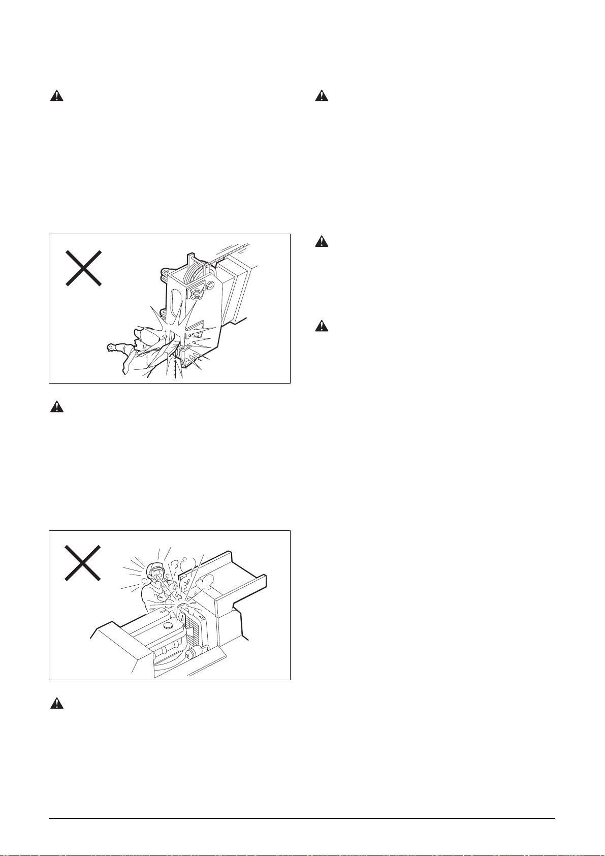
Keep Away from Moving Parts
Inadvertent motion of the machine, or contacting a
moving part can cause personal injury and even
death.
When necessary to inspect or maintain the machine
while running, do not approach moving parts such
as the boom, elevating cylinder, winch, fan, fan belt,
and propeller shaft, etc.
Keep hands and clothing away from moving parts.
Beware of an Overheated Cooling
Do Not Allow Tools and Parts to Drop
When working through an inspection hole while fac-
ing down, be careful not to drop objects into the
hole. Such mistakes can damage or lead to malfunc-
tion of the machine. Do not keep objects which are
not needed for inspection in open pockets.
Recover any object or tool that has dropped into the
machine.
Beware of Oil Smears
Oil smears on the clutch, lining and brake disks can
decrease braking effectiveness. Always keep these
assemblies free from oil accumulation.
Beware of Dust
Be careful not to inhale dust during inspection or
maintenance work. To inspect or maintain brakes
and linings, remove dust using a vacuum cleaner.
Do not use compressed air because this action will
scatter dust into the air.
System
Do not unfasten the radiator cap while the engine
cooling water is hot. Hot steam and water can spurt
out, causing burns.
First allow the radiator to cool down. Then, loosen
the cap very slowly while facing away to release the
internal pressure.
T00044
Lock the Inspection Hole Covers
An inspection hole cover that remains open can be
closed abruptly by a gust, etc., causing hands or a
leg to be caught and injured.
If an inspection hole cover or access door, or the
operator’s cab door must remain open, secure in po-
sition.
Safety Rules Safety Rules
A-26
Page 28
T019605E
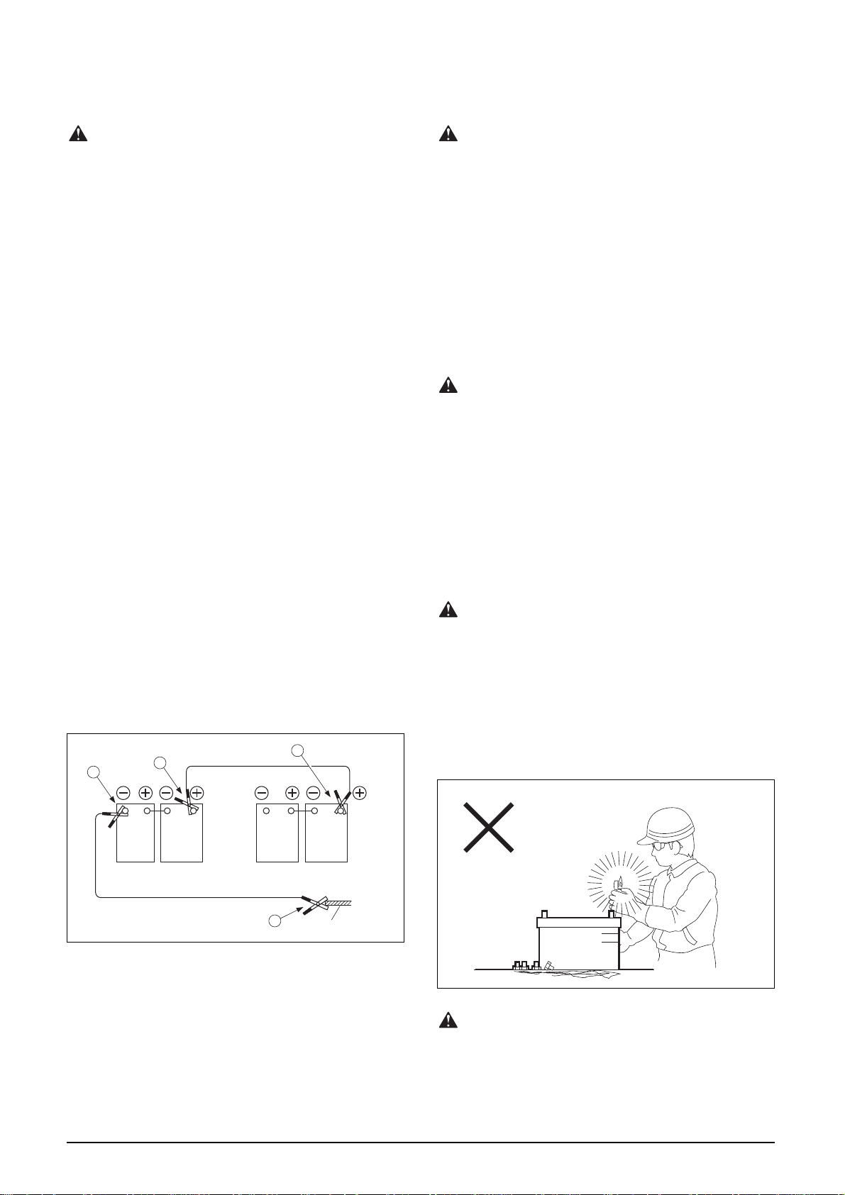
T21796E
1
4
2
3
Service vehicle battery
Booster cable
Booster cable
Disabled vehicle battery
Frame
About Starting the Engine with
Booster Cables
Using improper booster cables to start the engine
can cause the battery to explode or damage the ma-
chine.
When starting the engine using booster cables,
wear protective goggles. This procedure requires
two persons; one person must be seated in the op-
erator’s cab. The procedure consists of:
(1) Use an assist vehicle with a battery rated for 24
V. Do not use a 12 V or 48 V supply.
(2) Set the starter key to “OFF” position both for the
dead vehicle and assist vehicle.
(3) Connect the booster cables in the following or-
der:
[1] “+” terminal of the battery on the dead vehi-
cle.
[2] “+” terminal of the battery on the assist vehi-
cle.
[3] “-” terminal of the battery on the assist vehi-
cle.
[4] A portion of the frame or engine block of the
dead vehicle, apart from its battery.
(4) Start the engine of the assist vehicle.
(5) Start the engine of the dead vehicle.
(6) Once the engine of the dead vehicle has suc-
cessfully started, disconnect the booster cables
in the order of [4], [3], [2] and [1].
Disconnect the Battery Cable before
Inspecting or Maintaining the Electrical
System
Inspecting or maintaining the electrical system with-
out disconnecting the battery cable can cause the
wiring to be shortcircuited, possibly damaging the
electrical and electronic systems.
Before inspecting or maintaining the electrical sys-
tem, disconnect the battery cable from the minus
terminal (ground side) of the battery.
Be Cautious about Battery Fluid
The battery fluid contains dilute sulfuric acid.
Battery fluid entering the eyes could cause blind-
ness, and battery fluid on skin can cause burns.
When handling the battery, wear protective goggles,
protective gloves, and long-sleeved clothing.
If battery fluid touches your eyes or skin, wash with
a large amount of fresh water and seek medical at-
tention immediately.
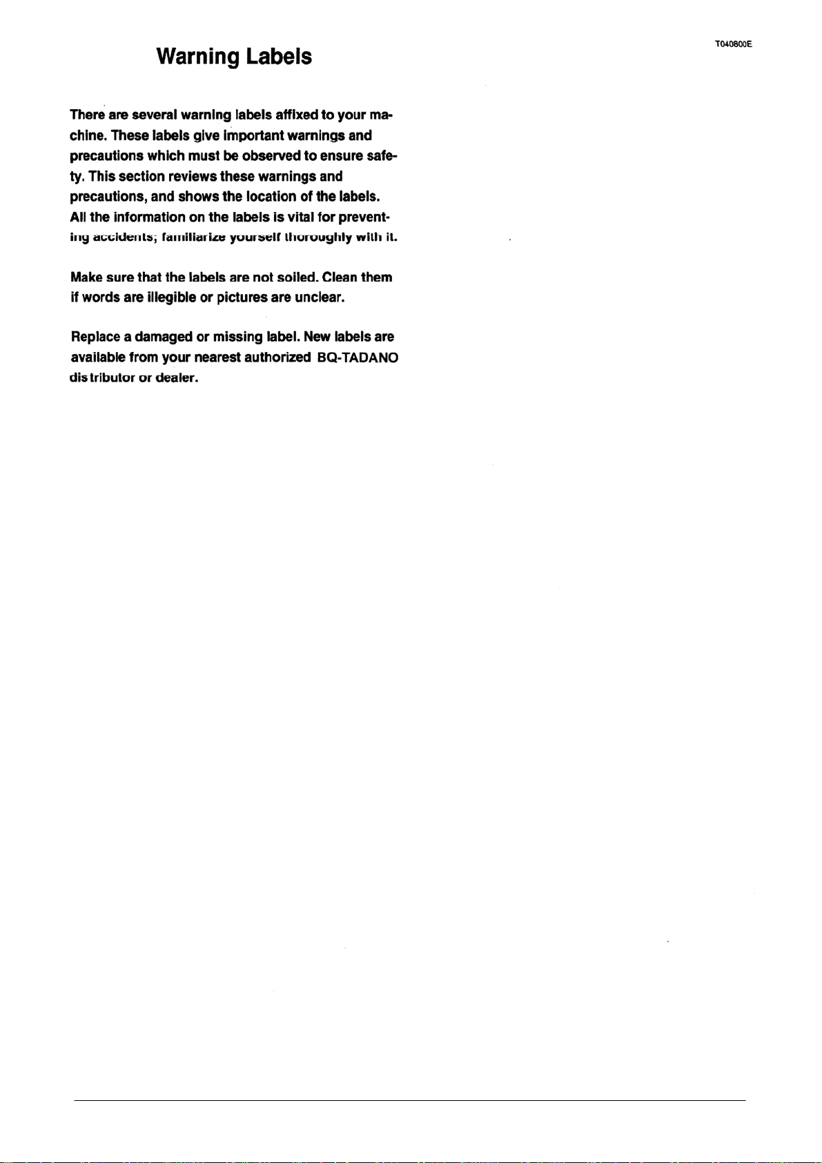
Prevent Explosion of the Battery
The battery releases hydrogen gas. Do not light a
match or lighter near the battery.
To check the battery fluid level, use a flash light.
If battery fluid is frozen in extreme freezing weather,
do not charge the battery or start the engine with an
alternative power supply.
Warm up the battery to 15°C so to avoid trouble.
Safety Rules Safety Rules
H
L
Careful Handling of Wire Ropes
Careless handling of wire ropes can shorten their
service life, or cause them to break. Handle wire
ropes properly by observing all instructions in the
manual.
A-27
T00043
Page 29

Safety Rules Safety Rules
A-28
Page 30
Warning Labels Warning Labels
A-29
Page 31

Warning Labels-Location and Contents
1. PROHIBITION OF CLIMBING ON BOOM
JIB AND OUTRIGGERS
2. CAUTION TO BOOM IN MOTION
3. JIB PIN STATUS
4. WARNING IN JIB OFFSET
5. WARNING ON STOWING THE SINGLE TOP
6. JIB HANDLING INSTRUCTIONS
7. CAUTION TO BOOM SWING
8. CAUTION IN JIB OFFSET
9. WARNING ON TOP JIB
10. CAUTION IN HANDLING JIB
Warning Labels Warning Labels
11. CAUTION TO OVERRIDE FUNCTION
12. CAUTION TO LIVE LINES
13. CAUTION IN HANDLING OVERRIDE KEY
SWITCH
14. CAUTION TO OIL COOLER FAN
15. CAUTION IN HANDLING CONTROL
CONSOLE
16. CAUTION IN HANDLING SWING ROCK PIN
17. STOWING AUXILIARY WINCH ROPE
A-30
Page 32

1.
ᨌᨎᨋᨄᨅ᧾ᨅᨐᨅᨋᨊ ᨋᨂ ᧿ᨈᨅᨉ᧾ᨅᨊᨃ ᨋᨊ ᧾ᨋᨋᨉ᧨
ᨆᨅ᧾ ᧽ᨊᨀ ᨋᨑᨐᨎᨅᨃᨃᨁᨎᨏ
᧿᧽ᨑᨐᨅᨋᨊ ᨐᨋ ᧾ᨋᨋᨉ ᨅᨊ ᨉᨋᨐᨅᨋᨊ
2.
3. JIB PIN STATUS
Warning Labels Warning Labels
A-31
Page 33

4. WARNING IN JIB OFFSET
᧿᧽ᨑᨐᨅᨋᨊ ᨐᨋ ᧾ᨋᨋᨉ ᨏᨓᨅᨊᨃ
5. WARNING ON STOWING THE SINGLE TOP
6. JIB HANDLING INSTRUCTIONS
7.
Warning Labels Warning Labels
A-32
Page 34

8. CAUTION IN JIB OFFSET
᧿᧽ᨑᨐᨅᨋᨊ ᨅᨊ ᨄ᧽ᨊᨀᨈᨅᨊᨃ ᨆᨅ᧾
᧿᧽ᨑᨐᨅᨋᨊ ᨐᨋ ᨈᨅᨒᨁ ᨈᨅᨊᨁᨏ
᧿᧽ᨑᨐᨅᨋᨊ ᨐᨋ ᨋᨅᨈ ᧿ᨋᨋᨈᨁᨎ ᨂ᧽ᨊ
9. WARNING ON TOP JIB
12.
10.
11. CAUTION TO OVERRIDE FUNCTION
WARNING
WHEN THE OVERRIDE KEY SWITCH LOCATED OUTSIDE THE
CRANE CAB IS ACTIVATED, AND THE AML OVERRIDE KEY
SWITCH LOCATED IN THE RIGHT SIDE OF THE AML IS IN
OVERRIDE, THE SYMBOL LIGHTS UP.
ALL SAFETY STOP FUNCTION WILL BE DISABLED WITH THIS
LIGHT ON.
CONTINOUS SAFE OPERATION IS CONTRLED ONLY BY THE
OPERATOR
13.CAUTION IN HANDLING OVERRIDE KEY
SWITCH
WARNING
THIS KEY SWITCH BYPASSES CONTROL LEVER
LOCKOUT FUNCTION OF AUTOMATIC MOMENT LIMITER
(AML-L). THE SWITCH MAY BE ONLY USED BY
AUTHORIZED PERSONNEL DURING EMERGENCY
SITUATIONS. FAILURE TO FOLLOW THIS INSTRUCTION
MAY RESULT IN PROPERTY DAMAGE AND OR
PRESONAL INJURY.
14.
Warning Labels Warning Labels
A-33
Page 35

15.
&$8 7,21,1+$1' /,1*& 21752/
&2 162/(
WARNING
PULL THE CONTROL CONSOLE BACKWARD TO THE
STOWING POSITION WHEN TRAVELING OR GETTING OUT
OF THE CAB.
)2/'837+($505(67%()25($'-867,1*7+($1*/(
2)&21752/&2162/
7$.(&$5(72&/26(7+('225:+(17+(&21752/
&2162/(,6835,*+7
16. CAUTION IN HANDLING SWING ROCK
PIN
CAUTION
ᨑᨏᨁᨐᨄᨁᨏᨓᨅᨊᨃᨈᨋ᧿ᨇᨀᨑᨎᨅᨊᨃ᧿ᨎ᧽ᨊᨁ
ᨋᨌᨁᨎ᧽ᨐᨅᨋᨊ᧪
ᨐᨄᨁᨏᨓᨅᨊᨃᨈᨋ᧿ᨇᨅᨏᨁᨊ᧽᧾ᨈᨁᨀᨋᨊᨈᨕᨓᨄᨁᨊᨐᨄᨁ
᧾ᨋᨋᨉᨂ᧽᧿ᨁᨏᨐᨄᨁᨂᨎᨋᨊᨐᨋᨎᨎᨁ᧽ᨎ᧪
17. STOWING AUXILIARY WINCH ROPE
Warning Labels Warning Labels
A-34
Page 36

Contents Contents
1
Page 37

Contents Contents
2
Page 38

Page 39

Servicing and Ordering Parts
When contacting the TADANO distributor or dealer for
repairs or to order parts, please specify the following
information:
(1) Specification number
(2) Production serial number
(3) Year of production
(4) Details of the problem, or the listing, number and
quantity of desired parts
Servicing and Ordering Parts
4
Servicing and OrderingParts
Page 40

Components
The directional terms (front, rear, right and left) used in
this manual are defined with reference to the driver's
position when seated in the carrier driver's cab. Their
definitions remain the same even when the crane's upper
structure is turned.
ƹ The illustrations may slightly differ from the actual
machine, due to designing alteration.
Components Components
5
Page 41

Layout of Controls Layout of Controls
of Controls
6
Page 42

1. AML cancellation warning lamp ・・・・・・・・・・・・・29
2. Jib lock indicator lamp ・・・・・・・・・・・・・・・・・・・100
3. Hydraulic oil pressure 50°C indicator lamp・・・・・126
4. Hydraulic oil pressure 85°C warning lamp ・・・・・126
5. Boom telescoping operation indicator lamp ・・・・・75
6. Auxiliary hoist operation indicator lamp ・・・・・・・・72
7. Boom telescoping mode II indicator lamp ・・・・・・75
8. Boom telescoping mode I indicator lamp ・・・・・・・75
9. Low noise mode switch ・・・・・・・・・・・・
10. Front wiper switch ・・・・・・・・・・・・・・・・・・・・・・126
11. Front washer switch ・・・・・・・・・・・・・・・・・・・・・126
12. Swing free/lock selector switch ・・・・・・・・・・・・・・84
13. Boom telescoping /auxiliary hoist control selector
switch ・・・・・・・・・・・・・・・・・・・・・・・・・・・・・
14. Boom telescoping mode I/II switch ・・・・・・・・・・・75
15. AML (overload prevention device)・・・・・・・・・・・・29
16. Winch drum rotation indicator (option) ・・・・・・・・・72
17. Overwind cutout release switch・・・・・・・・・・・52, 72
18. AML override switch・・・・・・・・・・・・・・・・・・・・・・29
19. Swing brake switch ・・・・・・・・・・・・・・・・・・・・・・84
20. Swing stop override switch
21. Slow elevation stop switch ・・・・・・・・・・・・・・・・・81
22. Starter switch ・・・・・・・・・・・・・・・・・・・・・・・・・・54
23. Accelerator lock knob・・・・・・・・・・・・・・・・・・・・・70
24. Cigarette lighter ・・・・・・・・・・・・
25. Ashtray ・・・・・・・・・・・・・・・・・・・・・・・・・・・・・・126
26. Boom elevating control lever ・・・・・・・・・・・・・・・81
27. Main hoist control lever ・・・・・・・・・・・・・・・・・・・72
28. Accelerator pedal・・・・・・・・・・・・・・・・・
29. Lever stand unlock lever ・・・・・・・・・・・・・・・・・・66
30. Boom telescoping /auxiliary hoist control lever
・・・・・・・・・・・・・・・・・・・・・・・・・・・・・・・・・・・72, 75
31. Head/end boom extension switch ・・・・・・・・・・・・75
32. Horn switch ・・・・・・・・・・・・・・・・・・・・・
33. Swing control lever ・・・・・・・・・・・・・・・・・・・・・・84
34. Boom telescoping control pedal ・・・・・・・・・・・・・75
35. Boom elevating control pedal ・・・・・・・・・・・・・・・81
36. Power window switch・・・・・・・・・・・・・・・・・・・・・66
37. Heater control panel (option) ・・・・・・・・・・・・・
38. Oil reservoir・・・・・・・・・・・・・・・・・・・・・・・・・・・・70
・・・・・・・・・・・・・・・・・84
・・・・・・・・・・・・126
・・・・・・126
72, 75
・・・・・・・70
・・・・・・・84
・125
T038261E
136
Layout of Controls Layout of Controls
7
Page 43

T038261E
54
D E F
MODE
C
OO
L
H
OT
O
N
O
F
F
A
/
C
R
/
F
ON
ON
ON
INT
3B
〜
2B
39 40 41 42 43 44 45 46 47
52
51
53
48
49
50
48
39. Roof washer switch ・・・・・・・・・・・・・・・・・・・・・126
40. Roof wiper switch・・・・・・・・・・・・・・・・・・・・・・・126
41. Flood lamp switch ・・・・・・・・・・・・・・・・・・・・・・126
42. Oil cooler switch ・・・・・・・・・・・・・・・・・・・・・・・126
43. Emergency outrigger control switch ・・・
44. Emergency outrigger control indicator lamp ・・・・・29
45. 2nd boom emergency telescoping switch ・・・・・・75
46. 3rd/4th/top boom emergency telescoping switch
・・・・・・・・・・・・・・・・・・・・・・・・・・・・・・・・・・・・・75
・・・・・・・29
47. Air conditioner control panel (option) ・・・・・・・・・119
48. Cab lamp ・・・・・・・・・・・・・・・・・・・・・・・・・・・
49. Seat ・・・・・・・・・・・・・・・・・・・・・・・・・・・・・・・・・66
50. Fan switch (option)・・・・・・・・・・・・・・・・・・・・・・126
51. Override key switch ・・・・・・・・・・・・・・・・・・・・・・29
52. Swing lock lever・・・・・・・・・・・・・・・
・・・・・・・11, 84
53. Power window close switch ・・・・・・・・・・・・・・・・66
54. External warning lamps ・・・・・・・・・・・・・・・・・・・52
T24020
・126
Layout of Controls Layout of Controls
8
Page 44

Terminology
Lifting height
Load radius
Center of rotation
T102540E
Boom angle
T24419E
Boom length
T038270E
This section provides the meaning of some important
terms used in this manual.
Load Radius, Lifting Height
"Load radius" refers to the horizontal distance between
the crane's center of rotation and the vertical center of
the lifted load.
A "lifting height" is defined for each load radius and
refers to the vertical distance between the ground and
the bottom of the hook block raised to its uppermost po-
sition.
Maximum Lifting Height
"Maximum lifting height" refers to the maximum lifting
height allowed.
Jib Length, Jib Offset Angle
"Jib length" refers to the center-to-center distance as il-
lustrated in the figure below.
"Jib offset angle" refers to the angle formed by the cen-
terline of an extended jib and the centerline of the boom.
Jib offset angle
Jib length
T20019E
Rated Lifting Capacity
"Rated Lifting capacity" refers to the maximum allowable
load for a particular boom length and load radius. The
mass of load handling devices such as hook blocks and
slings, shall be considered part of the load and must be
deducted from rated lifting capacities.
The mass of individual hook blocks are indicated in the
"INFORMATION AND DATA" section at the end of this
manual.
Boom Length, Boom Angle
"Boom length" refers to the distance from the pivot pin at
the foot of the boom to the center axis of the sheave (s)
at the boom head.
"Boom angle" refers to the angle formed by the boom's
centerline and the horizontal.
Mass of hook block
Rated lifting capacity
Lifting capacity
T21566E
Without Load
"Without load" is used to indicate that no load is being
lifted on the hook block.
Terminology Terminology
9
Page 45

T038270E
Over-front
Over-side
Over-side
Over-rear
T00052E-1
Stability Section, Strength Section
"Stability section" refers to the section of the rated lifting
capacities table in which the major factor for determining
lifting capacity is the stability of the crane.
"Strength section" refers to the section of the rated lifting
capacity table in which the major factor for determining
lifting capacity is the structural strength of the crane.
In the rated lifting capacities table, the capacities given
above the blue line are those determined based on
structural strength, and the capacities given below are
determined based on stability.
Over-front, Over-rear, Over-side
"Over-front" refers to the forward working area of the
carrier for which lifting capacities have been rated and
listed in the rated lifting capacities table.
"Over-rear" corresponds to the rear working area for
which lifting capacities have been rated and listed in the
rated lifting capacities table.
"Over-side" refers to the working areas not included in
"over-front" and "over-rear".
Outrigger Extension Widths
"Outrigger extension width" refers to the horizontal dis-
tance between the centers of the right and left outrigger
floats when the outriggers are extended.
(1) Full extension width of outriggers (L1)
The distance between outriggers when they are fully
extended.
(2) Middle extension width of outriggers (L2)
The distance between outriggers when they are ex-
tended halfway.
(3) Minimum extension width of outriggers (L3)
The distance between outriggers when they are not
extended.
L 3
L 2
L 1
T00053
Over-front, Over-rear and Over-side
Capacities
"Over-front capacity", "over-rear capacity" and "over-
side capacity" refer to the rated lifting capacity that can
be lifted in the over-front, over-rear and over-side areas,
respectively.
360-degree Capacity
"360-degree capacity" means that the lifting capacities
are the same regardless of the area in which the load is
lifted.
Capacities with Outriggers at Full
Extension, Middle Extension and Minimum
Extension
(1) Capacities with outriggers at full extension
Lifting capacities specified for a crane supported on
fully extended outriggers.
(2) Capacities with outriggers at middle extension
Lifting capacities specified for a crane supported on
outriggers extended halfway.
(3) Capacities with outriggers at minimum extension
Lifting capacities specified for a crane supported on
outriggers not extended.
Raising Load Just Clear of Ground
This phrase is used to express the operation where the
load is hoisted up a few centimeters above the ground
and held at that position.
Terminology Terminology
10
Page 46

OPERATION
H000450E
Page 47

Carrier Traveling Procedure—
T24431E
Jib
Rope arrester
ON
Summary
T039000E
WARNING
This summary describes briefly the essential
steps for traveling the crane. For detailed informa-
tion on the individual procedures, refer to the
appropriate pages in this section of the manual.
Do not travel until you have a complete under-
standing of all the instructions and information
given in this section.
The precautions you must observed when trav-
eling are described in the "Safety" section at the
beginning of this manual. Carefully read the sec-
tion before traveling the crane.
If you find anything abnormal with the crane
during traveling, stop the operation immediately,
check and locate the cause, and repair any faulty
components. To prevent accidents, do not travel
until repairs have been completed.
Preparatory Steps
◆For detailed information on the individual procedures,
refer to the sections shown in parentheses.
1. Set the crane as described in "At the End of
Operation" of "Crane Operation Procedure-Summary"
section.
("Crane Operation Procedure-Summary" …………P. 13)
3. Check that the swing brake switch is turned on.
("Swinging the Boom" ………………………………P. 84)
OFF
ON
AML
AML
50℃
JIB LOCK
85℃
ON
INT
FREE
H
L
E
U
F
L
◆Activate swing lock lever only to travel for a small dis-
tance with the crane out of traveling configuration for
unavoidable reasons.
Swing lock is not available while the boom is stowed on
the boom rest.
Swing lock lever
Swing brake switch
RELEASE
SWING LOCK
LOCK
(ON)
(OFF)
T24420E
2. Make sure that the wire rope is reeved through the
rope guide.
("Taking Out and Stowing the Main Hook Block"
……………………………………………………P. 88)
T30142E
Carrier Traveling Procedure—Summary Carrier Traveling Procedure—Summary
11
Page 48

Outrigger Operations for Traveling a
e
e
s
r
.
,
e
5
g
th
T
a
d.
.
k
-
.
Outrigger Operations for Traveling a
Small Distance
Small Distanc
WARNING
If the crane is moved without proper traveling
precautions, it may overturn.
For traveling without setting the crane in traveling
configuration, make the following preparations for
preventing overturning:
ake sure that the tire air pressure is kept at th
• Make sure that the tire air pressure is kept at the
2
pecified value (850 kPa [8.5 kgf/cm]). If the ai
specified value (850 kPa [8.5 kgf/cm
pressure is not insufficient, inflate the tires.
pressure is not insufficient, inflate the tires
• Retract the boom fully (to the length of 11.1 m),
Retract the boom fully (to the length of 11.1 m)
set the boom angle to 45°, retract the jib fully (to
set the boom angle to 45, retract the jib fully (to
the length of 9.0 m), and set the jib offset angle
the length of 9.0 m), and set the jib offset angl
to 5°.
to
• Orient the boom directly forward or backward
rient the boom directly forward or backward
and fix it with the swing lock pin before applying
nd fix it with the swing lock pin before applyin
the swing brake.
e swing brake.
• Observe the specified boom elevation angle. For
detailed information, refer to the “Weight
Distribution Chart” in the INFORMATION AND
DATA section.
To prevent overturning, do not travel with a
o prevent overturning, do not travel with
load hoisted.
oad hoiste
To prevent overturning, do not perform crane
operation during traveling.
Do not travel on the soft ground. Otherwise the
tires may fall in the ground and the crane may
overturn.
For safety, avoid starting or stopping sudden-
ly.
]). If the air
T039000E
1.
Set the crane as in the above described warning.
2. If the front jack is already extended, retract it.
If the front jack is already extended, retract it
3. Perform the jack stowing operation until the jack
Perform the jack stowing operation until the jac
floats are raised slightly from the ground.
floats are raised slightly from the ground.
4. Travel slowly at the speed below 5 km/h paying at-
4
Travel slowly at the speed below 5 km/h paying at
tention to the surroundings.
tention to the surroundings
5. After traveling, set the outriggers immediately.
Carrier Traveling Procedure—Summary Carrier Traveling Procedure—Summary
12
Page 49

Crane Operation Procedure—
O
F
F
O
N
AML
MIKUNIMIKUNI
MY30
F
U
E
L
L
H
JIB LOCK
AML
50℃
85℃
ON
INT
FREE
4
D E F
MODE
C
O
OL
H
OT
O N
O F F
A
/
C
R
/
F
O
N
O
N
ON
INT
3B
〜
2B
5
3
2
1
1
T24037
Summary
T038280E
WARNING
This summary describes briefly the essential
steps for crane operation from start to finish. For
detailed information on the individual procedures,
refer to the appropriate pages in this section of
the manual. Do not operate the crane until you
have a complete understanding of all the instruc-
tions and information given in this section.
The precautions you must observe during crane
operation are described in the "Safety" section at
the beginning of this manual. Carefully read the
section before operating the crane.
If you find anything abnormal with the crane
during operation, stop the operation immediately,
check and locate the cause, and repair any faulty
components. To prevent accidents, do not operate
the crane until repairs have been completed.
Preparatory Steps
3. Make sure that the controls in the crane operator’s
cab are in the following positions:
(1) Main and auxiliary hoist levers, boom telescoping
lever, boom elevating lever and swing lever …Neutral
(2) Swing brake switch ………………………………“ON”
(3) Swing stop override switch …………………Activated
(4) Slow elevation stop switch …………………Activated
(5) Emergency outrigger control switch ……………“OFF”
◆For detailed information on the individual procedures,
refer to the sections shown in parentheses.
1. Perform pre-operational inspection.
(“Pre-operational and Periodic Inspection” ………P. 132)
2. Enter the cab, and adjust the seat and each lever
stand so that the levers and all other controls can be op-
erated easily.
(“Crane Operator’s Cab” ……………………………P. 66)
Position for crane operation
Lever stand
Unlock lever
Stowage position
(for traveling)
T23069E
4. Start the engine by using the starter switch in the
carrier driver’s cab.
(“Starting and Stopping the Engine” ………………P. 54)
5. Engage the PTO.
(“Operating the PTO and Warming Up the Machine”
……………………………………………………P. 57)
6. Let the machine warm up. While it is warming up,
check that all meter and monitor displays are normal
and that the machine is not making any abnormal
sounds.
(“Operating the PTO and Warming Up the Machine”
……………………………………………………P. 57)
7. Fully extend the outriggers and level the crane.
(“Outriggers” …………………………………………P. 58)
8. Extend the front jack.
(“Outriggers” …………………………………………P. 58)
13
Crane Operation Procedure—Summary Crane Operation Procedure—Summary
Page 50

T038280E
9. Enter the crane operator’s cab, and adjust the seat
and the length of each lever so that you can easily oper-
ate the levers and all other controls.
(“Crane Operator’s Cab” ……………………………P. 66)
10.In the crane operator’s cab, turn the starter switch
ON.
11. Select the operational status on the AML.
(“AML <Overload Prevention Device>” ……………P. 24)
12.Take out the main hook block from its stowed posi-
tion.
(“Taking Out and Stowing the Main Hook Block” …P. 88)
13.Perform the preoperational checks for after the en-
gine has been started.
(“Preoperational and Periodic Inspection” ………P. 132)
14.Reeve the wire rope round the main hook block
sheaves as required for the operation.
◆Register the number of part lines of rope on the AML if
the actual number is smaller than the standard one.
(“Reeving the Wire Rope”……………………………P. 90)
15.Mount the single top or jib as necessary.
(“Single Top” …………………………………………P. 95)
(“Jib” …………………………………………………P. 100)
16.Select the operational status on the AML, when the
single-top sheave system or the jib is installed.
(“AML <Overload Prevention Device>” ……………P. 24)
During Operation
Follow the rated lifting capacity table to eliminate
1.
any possibility of overloading.
(“How to Read Performance Data Plate” …………P. 16)
(“Acceleration” ………………………………………P. 70)
(“Hoisting” ……………………………………………P. 72)
(“Telescoping the Boom” ……………………………P. 75)
(“Elevating the Boom” ………………………………P. 81)
(“Swinging the Boom” ………………………………P. 84)
(“Single Top” …………………………………………P. 95)
(“Jib” …………………………………………………P. 100)
◆When the AML activates an alarm in response to
overloading, take appropriate corrective measures.
(“AML <Overload Prevention Device>” ……………P. 24)
◆When an error occurs in the AML system, take the
corrective measure indicated by the failure message dis-
played on the AML.
(“AML <Overload Prevention Device>” ……………P. 24)
◆When a safety device other than the AML is activated
(such as the overwind cutout device), take the appropri-
ate corrective measures.
(“Other Safety Devices” ……………………………P. 52)
◆Use the air conditioner, and other equipment in the
crane operator’s cab, as necessary.
(“Equipment Inside the Cab” ………………………P. 125)
◆When the ambient temperature is high, use the oil
cooler as necessary.
(“Equipment Inside the Cab” ………………………P. 125)
Crane Operation Procedure—Summary Crane Operation Procedure—Summary
14
Page 51

T038280E
T23069E
Lever stand
Unlock lever
Stowage position
(for traveling)
Position for crane operation
At the End of Operation
Stow the single top or jib.
1.
(“Single Top” …………………………………………P. 95)
(“Jib” …………………………………………………P. 100)
2. Stow the main hook block and stow the boom on
the boom rest.
(“Taking Out and Stowing the Main Hook Block”
……………………………………………………P. 88)
3. Make sure that the controls in the crane operator’s
cab are in the following positions:
(1) Hoist, boom telescoping, boom elevating, and swing
levers ……………………………………………Neutral
(2) Swing brake switch ………………………………“ON”
4. Return the lever stand to the stowage position.
11. Disengage the PTO.
(“Operating the PTO and Warming Up the Machine”
……………………………………………………P. 57)
12.Stop the engine by using the starter switch in the
carrier driver’s cab.
(“Starting and Stopping the Engine” ………………P. 54)
13.Perform the post-operational checks for the same
points as for the pre-operational checks. If anything ab-
normal is found, have it repaired before operating the
crane again.
5. Shut off the air conditioner, oil cooler and all other
equipment.
(“Equipment Inside the Cab” ………………………P. 125)
6. Close all the crane operator’s cab windows.
7. Remove the key from the starter switch in the crane
operator’s cab.
(“Starting and Stopping the Engine”…………………P.54)
8. Get out of the crane operator’s cab and lock the
door.
(“Crane Operator’s Cab” ……………………………P.66)
9. Retract the front jack.
(“Outriggers” …………………………………………P. 58)
10.Retract the outriggers completely.
(“Outriggers” …………………………………………P. 58)
Crane Operation Procedure—Summary Crane Operation Procedure—Summary
15
Page 52

How to Read Performance Data
Plate
Working Radius/ Lifting Height Chart
ƹ The following diagram is an example of the
working radius/ lifting height chart. The chart for your
crane is located inside the crane operator's cab.
The working radius/ lifting height chart provides the
load radii and lifting heights in relation to different
boom lengths (jib lengths) and boom angles (jib offset
angles). Use the chart in conjunction with the rated
lifting capacity table when making an operation plan.
ƹWhile points A and B in the figure are at the same
load radius, point A denotes the boom angle (or jib
offset angle), and point B the lifting height.
ƹThe working radius/ lifting height chart does not in-
clude the effect of boom deflection. The greater the
mass o(the load is, the more the boom deflects,
causing the load radius to increase somewhat. Take
this effect into consideration when reading the
working radius / lifting height chart.
How to Read Performance Data Plate How to Read Performance Data Plate
16
Page 53

Boom Telescoping Mode and Boom Length
and Boom Length
The telescoping mode I (the 2nd boom section extends
first during boom extension) and the telescoping mode II
(the 3rd through top boom sections extend first during
boom extension) are available. When the boom length is
any of the values listed in the load radius /lifting height
chart and the rated lifting capacity table, the boom con-
dition is among the one shown below.
How to Read Performance Data Plate How to Read Performance Data Plate
17
Page 54

Rated Lifting Capacity Table
WARNING
The values shown in the rated lifting
capacity table are based on ideal conditions
where the crane is set level on a firm surface,
there is no wind or side load, and the load is
not swinging. When operating the crane under
these conditions is not possible, reduce the
load as necessary according to the actual
operating conditions.
ƹThe table shown below is an example of the rated
lifting capacity table. The rated lifting capacity table
for your crane is located in the crane operator's cab.
ƹIn the rated lifting capacity table, the values above
the blue line are based on the structural strength of
the crane, whereas the values below that line are
based on the stability of the crane.
ƹThe stability limit of the rated lifting capacities
does not exceed the values calculated in the Part
2/ISO 4305.
ƹFor the rated lifting capacities for the boom
lengths which are not listed in the chart, see the
AML display.
Rated lifting capacities tables are set up as shown
below with the kind of job and the outrigger
extension conditions. For actual values see the
rated lifting capacity tables provided in the crane
operator's cab.
Operation Outrigger extension
• Boom lift
• Single top lift
• Jib lift
Full extension (6.8 m)
Middle extension (4.6 m)
Minimum extension (2.39 m)
Full extension (6.8 m)
Middle extension (4.6 m)
How to Read Performance Data Plate How to Read Performance Data Plate
18
Page 55

Below are some examples of rated lifting capacities
tables.
[Example 1: Boom lift with outriggers fully extended ]
T-550E-2 RATED LIFTING CAPACITIES (BOOM)
GT-550E-2 RATED LIFTING CAPACITIES (BOOM)
UNIT˖kg CLASS OF CRANE˖C3
Outrigger max extended6.8m
Working radius
3.0 55,000 40,000 28,000 20,000
3.5 43,700 40,000 28,000 20,000
4.0 38,500 38,100 28,000 20,000
4.5 34,200 33,800 28,000 19,800 20,000 14,000
5.0 30,800 30,400 28,000 19,000 20,000 14,000
5.5 27,800 27,400 27,200 18,200 20,000 13,600
6.0 25,400 25,000 24,700 17,500 20,000 12,800 14,000 8,000
6.5 23,200 22,800 22,500 16,800 18,900 12,000 14,000 8,000
7.0 21,400 21,000 20,700 16,200 17,800 11,400 13,500 8,000 8,000 8,000
7.5 19,700 19,300 19,100 15,700 16,700 10,800 13,000 8,000 8,000 8,000
8.0 18,300 17,900 17,600 15,200 15,800 10,200 12,500 8,000 8,000 8,000
9.0 15,200 14,600 14,200 14,300 14,200 9,300 11,300 7,600 8,000 8,000
10.0 11,600 11,300 13,500 12,500 8,500 10,400 7,000 7,500 8,000
11.0 9,500 9,100 11,400 10,300 7,800 9,600 6,400 6,900 7,500
12.0 7,800 7,500 9,600 8,600 7,200 8,800 5,800 6,400 6,900
14.0 5,100 7,200 6,200 6,200 6,800 4,900 5,500 5,900
16.0 3,500 5,500 4,500 5,400 5,100 4,200 4,700 5,200
18.0 3,300 4,700 3,900 3,600 4,100 4,200
20.0 2,400 3,700 3,000 3,200 3,600 3,200
22.0 1,700 3,000 2,200 2,800 2,800 2,500
24.0 1,200 2,400 1,600 2,500 2,200 1,900
26.0 1,200 2,100 1,800 1,400
28.0 800 1,700 1,400 1,000
30.0 500 1,400 1,000 700
32.0 1,100 700 450
34.0 500
Telescoping
mode
2nd boom 0 50 100 0 100 0 100 0 50 100
3rd boom 0 0 0 33 33 66 66 100 100 100
4th boom 0 0 0 33 33 66 66 100 100 100
Top boom 0 0 0 33 33 66 66 100 100 100
11. 1m
boom
ĉ,ϩ ĉ ĉ ϩ ĉ ϩ ĉ ϩ ϩ ĉ,ϩ
15.0m
boom
18.8m boom 26.6m boom 34.3m boom
Telescoping condition˄%˅
38.1m
boom
42.0m
boom
How to Read Performance Data Plate How to Read Performance Data Plate
19
Page 56

[Example 2: Jib lift with outriggers fully extended ]
UNIT˖kg CLASS OF CRANE˖&
Outrigger max extended 6.8m
42.0m Boom
8.8m Jib 15.2m Jib
Boom angle
80° 3500 2500 1400 2300 1150 750
75°
72°
70° 3000 2100 1320 1750 950 610
65° 2300 1900 1250 1440 880 560
5°offset 25°offset 45°offset 5°orffset 25°offset 45°offset
3500 2330 1380 2100 1040 670
3300 2250 1350 1950 1000 630
60° 1400
55° 750
Boom angle
80°
75°
72°
70°
65° 2300 1900 1250 1440 880 560
60° 1900 1600 1150 1220 830 520
55°
50° 950 850 800 650 550 450
45° 500 450 450
Boom angle
80°
75°
72°
70°
65° 2300 1900 1250 1440 880 560
60° 1900 1600 1150 1220 830 520
5°offset 25°offset 45°offset 5°offset 25°offset 45°offset
3500 2500 1400 2300 1150 750
3500 2330 1380 2100 1040 670
3300 2250 1350 1950 1000 630
3000 2100 1320 1750 950 610
1450 1350 1080 1100 750 490
5°offset 25°offset 45°offset 5°offset 25°offset 45°offset
3500 2500 1400 2300 1150 750
3500 2330 1380 2100 1040 670
3300 2250 1350 1950 1000 630
3000 2100 1320 1750 950 610
1300 1150 1100 830 520
700 650 500 400
UNIT˖kg CLASS OF CRANE˖&
Outrigger max extended6.8m
38.1m Boom (Telescoping modeϩ) or less than that
8.8m Jib 15.2m Jib
UNIT˖kg CLASS OF CRANE˖&
Outrigger max extended 6.8m
34.3m Boom (Telescoping modeĉ)or less than that
8.8m Jib 15.2m Jib
55°
50° 950 850 800 650 550 450
45° 500 450 450
1450 1350 1080 1100 750 490
How to Read Performance Data Plate How to Read Performance Data Plate
20
Page 57

Boom Lift
ĂĂĂ
γγ
γγ
γγ
γ
γ
γ
ĂĂĂ
Ċ ĂĂĂ
e
γ
γ
©
γ
Jib Lift
See the applicable section of the rated lifting capacity table and
find the rated lifting capacity value that corresponds to the boom
length and load radius
(1)
Use the section of the rated lifting capacity table that
corresponds to the status of the outriggers, front jack and
working area.
(2)
Take rated lifting capacity value W (tons) that corresponds
to the desired telescoping mode, load radius R (m) and boom
length L (m).
Load
radius(m)
Telescoping
mode
ƹ
The rated lifting capacity values for boom lift assume a
Outriggers fully extended
m
m
boom
boom •
R W
ĉ,Ċ ĉ ĉ
Lm boom
m boom
boom with jib and single top stowed.
ƹ
The rated lifting capacity values for boom lift are based on
the load radius. The load radii shown in the rated lifting capacity
table include the deflection of the boom under the mass of a
load. When determining capacity from the table, therefore, find
the rated lifting capacity value based on the actual measured
load radius.
ƹ
When the actual boom length exceeds the length specified
for a certain boom extension, check the rated lifting capacity
value for the specified length and for one stage longer, and use
the smaller of the two. (The value may be different from that
indicated by the AML)
ƹ
When the front jack is not extended, note that the lifting
capacity in the over-front area is poorer than in the over-rear
and over-side areas. Keep this in mind when swinging the load
from the over-rear or an over-side area to the over-front area.
ƹ
The mass of load handling devices such as hook blocks
and slings, shall be considered part of the load and must be
deducted from rated lifting capacities.
See the applicable section of the rated lifting capacity table and
find the rated lifting capacity value that corresponds to the boom
length and load radius.
(1) Use the section of the rated lifting capacity table that
corresponds to the status of the outriggers, front jack,
working area, boom length and boom telescoping mode.
(2)
Take rated lifting capacity value W (tons) that corresponds
to the desired jib length L (m), jib offset angle (°) and boom
angle (°).
Boom
angle
ƹ
The mass of load handling devices such as 4.5-ton hook
Outriggers fully extended
Telescoping mode
Lm Jib
offset
R
25' offset 45* offset
R
W
R
and slings, shall be considered part of the load and must be
deducted from rated lifting capacities.
Single Top Lift
ingle Top Lift
For operations with the single top mounted, use the boom lift
section of the rated lifting capacity table to find the allowable
load. Find the rated lifting capacity value based on boom
length and load radius. From that value, subtract the mass of
the main hook block. The resultant value is the rated lifting
capacity for a single top lift. However, remember that the
maximum rated lifting capacity for a single top lift is 4,500 kg.
When the result of the above calculation (< table value > - <
main hook block mass >) is over 4,500 kg, always regard the
main hook block mass >) is over 4,500 kg, always regard the
ated lifting capacity as 4,500 kg.
rated lifting capacity as 4,500 kg.
How to Read Performance Data Plate How to Read Performance Data Plate
21
Page 58

T038290E
Working Area Chart
WARNING
While the swing stop override switch is shifted
to OFF, the crane does not automatically stop
even if it is overloaded by boom swing from an
area allotted with greater lifting capacities to an
area allotted with smaller lifting capacities.
Do not turn the swing stop override switch to OFF
unless for unavoidable reasons.
Applicable rated lifting capacities change as the ranges
of the over-front area, the over-side areas, and the over-
rear area vary, depending on the outrigger extension
width and whether the front jack is used.
The following figures show examples of the rated lifting
capacity in each condition.
The diagram indicating the working ares and their corre-
sponding rated lifting capacities for your crane is
included in the data plate file located in the crane opera-
tor’s cab.
Select the diagram that agrees with the desired condi-
tion of outrigger and front jack and see the lifting
capacity for each working area.
Traveling direction
N
K
L
M
Left Right
DC
MM
LL
KK
Front
A
G
Rear
B
H
I
J
K
L
M
F
E
T24321E
A: Over-front area
B: Over-rear area
C: Over-side area (right)
D: Over-side area (left)
E: Rated lifting capacity (capacity with outriggers at mini-
mum extension)
F: Rated lifting capacity (capacity with outriggers at mid-
dle extension)
G: Rated lifting capacity (capacity with outriggers at full
extension)
H: Minimum extension width of outriggers
I: Middle extension width of outriggers
J: Full extension width of outriggers
K: Position of outrigger jack with the beam not extended
L: Position of outrigger jack with the beam extended
halfway
M:Position of outrigger jack with the beam extended ful-
ly
N:Front jack
333-959-01140-0
How to Read Performance Data Plate How to Read Performance Data Plate
22
Page 59

◆The area inside the bold line in the figure above
T30106E
340° 10°
0°
180°
90° 270°
145° 200°
Left front outrigger
fully extended
Right front outrigger
extended to middle
Front jack extended
Right rear outrigger
fully extended
Left rear outrigger
extended to middle
shows the applicable rated lifting capacities.
◆Black marks among K, L, and M represent the actual
positions of outrigger jacks. The black marks in the
above figure shows that the left and right outriggers are
extended fully.
–Example–
While the outrigger extension is as shown below and the
front jack is used (extended), the rated lifting capacities
determined for each working area for boom lift are as
follows:
(1) Over-front area (340°–10°): capacities with outrig-
gers at full extension
(2) Over-right area (10°–145°): capacities with outrig-
gers at middle extension
(3) Over-rear area (145°–200°): capacities with outrig-
gers at full extension
(4) Over-left area (200°–340°): capacities with outriggers
at middle extension
If the outrigger extension is as shown below, the lifting
capacity turns from the one with outriggers at full exten-
sion into the one with outriggers at middle extension
when the boom passes the left rear (200° point) while
swung from the over-rear area into the over-left area.
The lifting capacity turns from the one with outriggers at
middle extension into the one with outriggers at full ex-
tension when the boom is swung further into the
over-left area (340°–10°).
T038290E
How to Read Performance Data Plate How to Read Performance Data Plate
23
Page 60

AML (Overload Prevention
T23991
°
Device)
T038300E
WARNING
The AML operates properly only when it is
used exactly as instructed in this manual. If you
do not follow the specified AML and crane operat-
ing procedures, the crane could overturn or be
damaged, causing a serious accident. Be sure to
observe the following precautions for safe opera-
tion.
• Never perform any operation with the AML deac-
tivated.
• Place the crane on firm and level ground with
the outriggers extended and adjust the crane so
that it is level.
• Before starting operation, perform pre-opera-
tional checks on the AML to ensure that it is
operating properly.
• Always make sure that the actual outrigger ex-
tension width and the representation of the
outrigger extension width on the AML display
conform. Otherwise the crane may overturn.
• While the swing stop cancel switch is shifted to
OFF, swinging will not stop automatically even
if overloading occurs. The rated lifting capacity
may vary during boom swing, depending on the
outrigger extension width and the front jack
condition. When swinging the load to the area
allotted for smaller rated lifting capacities after
lifting it in the area allotted for greater rated lift-
ing capacities, pay attention not to overload the
crane after understanding the section “How to
Read Performance Data Plate”.
If the alarm buzzer sounds and the moment ratio
indication on the AML exceeds 100% while a
load is swung, stop swinging immediately. Then
lower the load or swing the boom back. (For the
specified values which trigger the alarm, see
“Configuration and Functions of the AML
System” section.)
• When the AML exceeds the specified value, the
alarm will sound intermittently. Slow the crane
operation and take great care. (For the specified
values, see the “Configuration and Functions of
the AML System” section.)
• Do not lift a load on the boom with the jib
mounted. If this must be done by unavoidable
reasons, a boom lift status, and not a jib lift sta-
tus, should be selected on the AML.
In this case, a precautionary warning is output
when the moment is below 75% and a limit warn-
ing is output when the moment is below 85%.
Remember that the warnings will be output earli-
er. (For the moment values corresponding to the
warning types, see the "Configuration and
Functions of the AML System".)
T50182
• Do not lift a single load using both the boom
and jib. If this must be done by unavoidable rea-
sons, a jib lift status, and not a boom lift status,
should be selected on the AML. (The figure
shows a 5° offset angle with the first jib section
extended.) Make sure that the mass of the load
(including the mass of the load handling de-
vices) is less than the specified rated lifting
capacity for the jib. If the load is left held up only
by the auxiliary wire rope when the main wire
rope is loosened, the load's center of gravity
moves to give an increased figure in moment
display. Take care to overloading.
AML (Overload Prevention Device) AML (Overload Prevention Device)
24
Page 61

T038300E
m
Automatic stop function for overloading
Automatic stop function by boom upper angle restric-
t
hil
.
2
.
Slow stop function
• When the crane is automatically stopped during
operation toward critical condition (hoisting up,
boom extension or boom lowering), operate the
appropriate controls to move toward the non-
critical condition (hoist down, retract boom or
raise boom).
• Do not raise the boom to raise the load clear of
the ground. Doing so is dangerous because the
crane will not stop automatically even when it is
overloaded. Hoist up the load to raise it clear of
the ground. Once the load has cleared the
ground, stop hoisting and check for safety.
[NOTICE]
◆While the elevating cylinder is extended or retract-
ed to the full stroke, the display of the AML becomes
erroneous. In this case, elevate the boom in the op-
posite direction to terminate the stroke end
condition.
Configuration and Functions of the
onfiguration and Functions of the
AML System
AML Syste
The AML (Automatic Moment Limiter) system is a safety
device provided to prevent overloading of the crane
which may cause it to overturn or be damaged.
The AML system has various kinds of functions, includ-
ing the following four typical functions. Based on the
registered work conditions by operator selection and the
signals from various sensors, the crane operations are
controlled.
(1) Automatic stop function for overloading
The AML calculates and compares the working and
rated moment values and displays them as a per-
centage. When the working moment exceeds the
rated moment (100% or more), failure message is
shown, alarm buzzer sounds, and the crane opera-
tion toward the critical side stops.
(2) Automatic stop function by boom upper angle restric-
tion
ion
To prevent jib from contacting the hook block or wire
rope during boom lift or single top lift, a message and
an alarm is output and boom raising and boom re-
traction are halted in the following conditions:
• The boom is raised over approx. 76° while the
• The boom is raised over approx. 76w
boom extension is less than approx. 2 m.
boom extension is less than approx. 2 m
• The boom extension is reduced less than approx. 2
• The boom extension is reduced less than approx.
m while the boom angle is over approx. 76°.
m while the boom angle is over approx. 76°
e the
AML (Overload Prevention Device) AML (Overload Prevention Device)
(3) Working range limit functions
When any working range limit is registered to AML,
the crane is controlled so that the crane work posture
does not exceed this registered working range limit.
When the boom reaches the previously registered re-
striction, buzzer sounds, and the crane operation
stops.
(4) Slow stop function
The elevating speed slows down before the boom
stops slowly in the following conditions:
• Boom (lowering) stopping by overloading
• Boom (raising) stopping by boom upper angle re-
striction
• Boom reaches the stroke end (while raised and
lowered)
• Boom (raising and lowering) stopping by working
range limit function
25
Page 62

The situation of automatic stop due to automatic stop
lly.
”
-
d.
function and working range limit function is as listed be-
low, depending on the working condition:
◎: Slow stop ○: Stop
Hoisting up ○
Automatic stop Boom lowering ◎
by overloading Boom extension ○
Swing ○
Boom upper Boom raising ◎
angle restriction Boom retraction ○
Stop at stroke end Boom raising/loweing ◎
Stop by working
range restriction
◆While the elevation slow stop cancel switch is in “OFF”
While the elevation slow stop cancel switch is in “OFF
position, the slow stop function for boom elevation is de-
position, the slow stop function for boom elevation is de
activated.
activate
◆While the automatic swing stop function is in “OFF”
While the automatic swing stop function is in “OFF”
position, swing does not stop automatically.
position, swing does not stop automatica
Boom raising/lowering ◎
Boom extension ○
Swing ○
T038300E
AML (Overload Prevention Device) AML (Overload Prevention Device)
26
Page 63

AML System Configuration
L
θ
θu
θL
H
R
Boom length signal
Outrigger extension
width detector
Boom angle signal Moment ratio signal Swing angle signal Crane control position
signal
Working range limit
signal output
Alarm buzzer
External warning
lamps
AML unit
Boom
extension
halted
Boom lowering
halted
Hoisting up
halted
Upper boom angle
restricted
Lower boom angle
restricted
Lifting height
restricted
Load radius
restricted
Outrigger status
Lift status
Working range limits
Operator selection
Stop output when:
Moment ratio exceeds 100%
Overwinding occurs
Moment exceeding limit for
boom with jib mounted
Boom raising
halted
Boom retracting
halted
Boom upper
angle
restriction
T24085E
Number of part-lines of rope
Swinging
halted toward
critical side
Swing restricted
T038300E
θ
L
Display panel
AML system error occurs
AML (Overload Prevention Device) AML (Overload Prevention Device)
27
Page 64

˄
˅
Automatic Stop Functions
r
g
g
Causes of
Operation
automatic stop
• Moment ratio
exceeds 100% (*1)
• Overwinding
• AML system erro
Upper boom angle
restricted
Lower boom angle
restricted
Lifting height
restricted
Load radius
Working range limit
restricted
Swing restricted • Boom swin
• Boom upper angle
restriction
• Boom lift
• Single top lift
• Jib lift
• Boom lift
• Single top lift
(*1): For the boom lift with the jib mounted,
automatic stop will work when the moment exceeds
85%.
Halted
movement
• Hoisting up
• Boom lowering
• Boom extension
• Boom swin
• Boom raising
• Boom lowering
• Boom raising
• Boom extension
• Boom lowering
• Boom extension
• Boom raising
• Boom retraction
Alarm Functions
Condition Alarm
Winch lever is moved
toward critical side (hoist
up, boom lowering or
boom extension) while
overwinding condition
exists.
Overwind cutout function
is released with the winch
overwound.
Moment ratio exceeds
90%
Moment ratio exceeds
100%
AML system error Moment display: Displays failure
Working range limit
function activated.
Slow stop control Moment display: Displays
Boom lift with jib mounted on boom
(1) Moment ratio is
between 75%and 85%
(2) Moment ratio exceeds
85%
Moment display: Displays
[Warning:0024].
Buzzer: Sounds continuously.
Moment display: Displays
[Warning:0015].
External warning lamps: Red
lamp is lit.
Buzzer: Sounds continuously.
Moment display: Yellow
segment(s) is lit.
External warning lamps : Orange
lamp is lit.
Buzzer: Sounds intermittently.
Moment display: Displays
[Warning:0023].
External warning lamps: Red
lamp is lit.
Buzzer: Sounds continuously.
messages.
Buzzer: Sounds 3 seconds.
Moment display: Displays failure
messages.
Associated restriction indicator
lamp flashes.
Buzzer: Sounds continuously.
AML buzzer: Sounds 3 seconds.
[Warning:0081]or[0082]
Buzzer: Sounds intermittently.
Moment display: Green
segment(s) is lit.
External warning lamps:
Orange lamp is lit.
Buzzer: Sounds intermittently.
Moment display: Displays
[Warning:0088].
External warning lamps : Red
lamp is lit.
Buzzer: Sounds continuously.
AML
ƹIn the above table, "Buzzer" is the device outside
the AML unit, outputting buzzing sound.
"AML buzzer" is the device inside the AML unit,
outputting beeping sound.
ƹThe AML buzzer sounds for 3 seconds every time
a message appears. It outputs long sounds when
slow stop control is activated and outputs short
sounds when other controls are activated.
Overload Prevention Device˅ AML˄Overload Prevention Device
28
Page 65

Controls
1
D
E
F
MO
DE
C
O
O
L
H
O
T
O N
O F F
A
/
C
R
/
F
ON
ON
ON
INT
3B
〜
2B
O
F
F
O
N
AML
MIKUNI
MY30
F
U
E
L
L
H
JIB LOCK
AML
50℃
85℃
ON
INT
FREE
1
6
5
2
T24147
4
3
T038300E
1. AML unit
2. AML override switch
3. Override key switch
AML Override Switch
Override Key Switch
These are emergency switches provided to stow the
boom when failure occurs in the AML system.
For details, see the “Disposition of System Troubles”
section.
Emergency Outrigger Control Switch
This switch is used to enable registering outrigger exten-
sion width temporarily on the AML and to sustain crane
operation while an error occurs on the outrigger exten-
sion detector.
◆For details, see the "Disposition of System Troubles"
section.
4. Emergency outrigger control switch
5. Emergency outrigger control indicator lamp
6. AML cancellation warning lamp
AML (Overload Prevention Device) AML (Overload Prevention Device)
29
Page 66

Names and Functions of AML Main
T23984E
%
t
m
max t
m
m
Bargraph display
Display panel 1
Control
Display panel 2
A
Unit Parts
ML LIIB
T038300E
AML (Overload Prevention Device) AML (Overload Prevention Device)
30
Page 67

Bargraph Display
T23213E
110 or more
than that
0–89 90–99
100–109
Each frame representing 10%
Each frame representing 2.5%
Each frame representing 2.5%
Usually on
1 23
4
T038300E
1. Moment ratio mark
The moment ratios on the bargraph are color coded as
follows:
safe (green), notice (yellow) and limit (red).
2. Moment display
Normally displays a moment ratio on a bargraph.
Displays the main-circuit oil pressure and torque con-
verter oil pressure when the display alteration key is
held down.
Also displays error messages when the AML or any of
its associated devices fail(s).
3. Scroll-up key
Used to see the previous lines of message displayed on
the moment display.
4. Scroll-down key
Used to see the next lines of messages displayed on the
moment display.
AML (Overload Prevention Device) AML (Overload Prevention Device)
31
Page 68

Display Panel 1
T23985
°
%
t
°
m
max t
m
m
17
20
21
16
18
17
10 9
31 2
13
19 11
14
15
7
8
5
6
T038300E
1. Jib angle display
When jib lift is selected, the jib angle offset is displayed.
When the number of part-lines of rope select key is
pressed, or the display select key is kept being pressed,
the number of part-lines of ropes is displayed. Also,
when the upper boom angle restriction function is acti-
vated, the registered upper boom angle limit value is
displayed as long as the register key is kept being
pressed.
2.
Number of part-lines of indicative symbol
This symbol shows that the jib angle display (1) indi-
cates the number of part-lines of rope
3. Boom length indicative symbol
This symbol, while marked up, means the value in the
boom length display [13] is a boom length value.
Jib angle indicative symbol
5.
Comes on to indicate that the value shown in the jib an-
gle display
represents the offset angle.
[1]
6. Jib lift indicative symbol
Comes on when the jib lift is selected to represent the
registered jib status.
7. Real load display
Displays the real load.
8. Rated lifting capacity display
Displays the rated lifting capacity.
9. Load radius limit restriction indicative symbol
Comes on to indicate that the value shown in the load
radius display [11] represents the load radius limit. Note
that the load radius indicative symbol [10] is also dis-
played at the same time.
10. Load radius indicative symbol
Indicates that the value shown in the load radius display
[11] represents the load radius.
11. Load radius display
Normally displays the crane's load radius.
When the load radius limit restriction function is activat-
ed, the load radius limit restriction value is displayed
while the register key is held down.
13. Boom length display
Usually displays boom length.
Displays the lifting height while the display alteration key
is pressed.
When the lifting height restriction function is effective,
this displays lifting height restriction value, while the reg-
ister key is being pressed.
14. Lifting height indicative symbol
This symbol, while marked up, means the value in the
boom length display [13] is a lifting height.
AML (Overload Prevention Device) AML (Overload Prevention Device)
32
Page 69

15. Lifting height restriction symbol
This symbol, while marked up, means the value in the
boom length display [13] is a lifting height restriction val-
ue.
The lifting height symbol [14] is marked up simultane-
ously.
16. Upper boom angle limit restriction symbol
Indicates that the jib angle display [1] displays the regis-
tered boom angle upper restricted value.
17. Boom angle indicative symbol
Indicates that the boom angle display [19] displays the
boom angle.
18. Lower boom angle limit restriction symbol
Indicates that the boom angle display [19] displays the
registered lower boom angle restricted value.
T038300E
19. Boom angle display
Normally displays the boom angle.
Displays the moment % when the display alteration key
is held down. When the restriction function is activated,
the lower boom angle limit restriction value is displayed
while the register key is held down.
20. Boom lift indicative symbol
Comes on when the boom lift is selected.
21. Single-top lift indicative symbol
Comes on when the single-top lift is selected.
AML (Overload Prevention Device) AML (Overload Prevention Device)
33
Page 70

Controls
7
6
5
15
18
19
1716
8
10
9
1113 1214
4321
T23214
20
T038300E
1. Increase key
Used to increase the selected value.
2. Decrease key
Used to decrease the selected value.
3. Outrigger mode select key
Used to select the outrigger status.
4. Lift mode select key
Used to select the lift status.
5. Check key
Used to check the AML system functions.
6. Register key
Used to register the selected state.
7. Display alteration key
Used to alternate the displays on display panel 1.
8. Load radius restriction key
Use to activate and cancel the load radius limiting func-
tion.
9. Load radius restriction indicator lamp
Lights up when the load radius limiting function is acti-
vated.
10. Lower boom angle limit restriction key
Used to activate and cancel the lower most boom angle
limiting function.
11. Lower boom angle limit restriction indicator lamp
Lights up when the lowermost boom angle limiting func-
tion is activated.
12. Upper boom angle limit restriction key
Used to activate and cancel the upper most boom angle
limiting function.
13. Upper boom angle limit restriction indicator lamp
Lights up when the uppermost boom angle limiting func-
tion is activated.
14. Lifting height restriction key
Used to activate and cancel the lifting height limiting
function.
15. Lifting height restriction indicator lamp
Lights up when lifting height limiting function is activated.
16. Right swing restriction key
Used to activate and cancel the right swing limiting func-
tion.
17. Right swing restriction indicator lamp
Lights up when the right swing limiting function is acti-
vated.
AML (Overload Prevention Device) AML (Overload Prevention Device)
34
Page 71

T038300E
T23986
3
2
2
3
3
3
2
4 1
2
18. Left swing restriction key
Used to activate and cancel the left swing limiting func-
tion.
19. Left swing restriction indicator lamp
Lights up when the left swing limiting function is activat-
ed.
Display Panel 2
20. Number of part-lines of rope select key
Used to register a number of part-lines of rope.
1. Front jack symbol
Indicates that the front jack is used.
2. Outrigger state indicative symbol
Displays the way the outriggers are extended.
3. "On-rubber" (Outrigger-not-in-use) state indicative
symbol
Comes on when the starter switch in the crane opera-
tor’s cab is turned “ON”.
5. Boom position indicator
Displays the boom position in 10° increments.
AML (Overload Prevention Device) AML (Overload Prevention Device)
35
Page 72

T038300E
Selecting Operational Status
WARNING
Should the operational status be incorrectly
registered, the crane might overturn or be dam-
aged, leading to a serious accident. Prior to every
operation, check that the registered status corre-
sponds to the actual status of the crane.
Selecting Outrigger Status
◆The "on-rubber" state indicative symbol is marked up
when the power supply is turned on (the PTO switch in
the carrier driver’s cab is turned ON after the engine is
started). (The outrigger state indicative symbols and
front jack symbol remain off.)
◆Turning the power off (PTO switch: OFF) automatical-
ly erases all the previous settings stored in memory after
approximately 2 hours. To resume the operation more
than 2 hours after the power has been last turned off,
enter the settings all over again.
When the outrigger mode select key is pressed, the out-
rigger state indicative symbols and front jack symbol
flash in accordance with the status that the AML detects
on.
After making sure that the display conforms to the actual
outrigger conditions, press the register key. The outrig-
ger state indicative symbol will change from flashing into
being marked up continuously and the moment display,
rated lifting capacity display and real load display will re-
turn to normal display conditions, meaning that the state
has been registered.
Actual outrigger status
Representation of outrigger
status on the AML
Register the outrigger status using the outrigger mode
select key and register key.
m
Front jack mode
indicative symbol
Outrigger state
indicative symbol
m
t
%
max t
m
Register key
Outrigger mode select key
T24099E
T24151E
Fully extended (6.8m)
Mid. extended (4.6m)
Min. extended (2.39m)
T24153E
◆If an outrigger or the front jack is stowed after registra-
tion of outrigger status, the registered status is erased.
In this case, register the outrigger status again before
starting crane operation.
AML (Overload Prevention Device) AML (Overload Prevention Device)
36
Page 73

Page 74

T038300E
t
max t
m
m
T24154E
Number of part-lines of rope
Number of part-lines of rope indicative symbol
Increase key
Decrease key
Number of part-lines of rope select key
Register key
Selecting Number of Part-lines of Rope
[NOTICE]
◆If the registered number of part-lines of rope is
smaller than the standard number, a maximum al-
lowable lifting load is limited, depending on the
registered number. In case the number is registered
as ‘0’, however, a process takes place as if the stan-
dard number were registered.
◆Similarly, a process takes place on the basis of
the standard number of part-lines of rope if the reg-
istered number is larger than the standard number
or other than the values specified for your model.
◆When the power supply is turned on (i.e. PTO switch
ON), the standard number of part-lines of rope corre-
sponding to a work condition is selected.
Register the number of part-lines of rope by use of the
number of part-lines of rope select key, as follows:
1. Press the number of part-lines of rope select key.
The number of part-lines of rope symbol will flash, and
the number of part-lines of rope will be shown on the jib
angle display in a flashing mode.
3. Once the intended number of part-lines of rope is
set, press the register key and register the number.
Then, the number of part-lines of rope symbol is turned
off and the jib angle display returns to a normal status.
◆The number of part-lines of rope can be confirmed by
2. Press the increase or the decrease key to set the
number of part-lines of rope at a desired value.
◆When the increase or the decrease key is pressed, a
pressing the display alteration key.
numeral showing the number of rope changes from
flashing to being marked up, showing a fixed value for
the increase or decrease.
◆When the increase or the decrease key is kept
pressed, the number of rope continuously increases or
decreases.
AML (Overload Prevention Device) AML (Overload Prevention Device)
38
Page 75

T038300E
AML Pre-operational Inspection
WARNING
Operating the crane with a malfunctioning
AML could cause the crane to overturn or be dam-
aged. Be sure to perform the pre-operational
inspection on the AML system and start the crane
only after ensuring that the system is operating
properly.
Before starting operation, check that the AML works in
good condition, as follows:
1. Press the check key and make sure that the AML is
in the following conditions:
• Moment display...............All segments are marked up.
• Display panel (1 and 2)...All segments are marked up.
• Working range restriction indicator lamp
........................................All six lamps light up.
• Alarm buzzer...................Sounds continuously.
• Movement toward critical sides
........................................Automatically halted
2. Press either the set key, display alteration key or
check key to return the display to the normal condition.
3. Make sure that the display on the display panels con-
forms to the actual crane conditions.
(1) Boom length
(2) Boom angle
(3) Jib angle......shown while jib lift is selected
(4) Real load.....Make sure that the approximate mass of
the hook block while no load is on the
hook block.
◆The real load is not shown correctly if the lift status
is not registered correctly.
(5) Outrigger state indicative symbol
(6) Front jack symbol
(7) Boom position indicator
◆If the AML does not work properly, have it checked
and repaired by the nearest TADANO distributor or deal-
er.
3
1
Buzz
Bargraph display
Display panel 1
m
m
t
%
max t
m
Display panel 2
Check key
7
6
5
m
t
°
max t
m
2
4
T24103
T24045E
AML (Overload Prevention Device) AML (Overload Prevention Device)
39
Page 76

T038300E
T24155E
R
Load radius restricted
H
Lifting height restricted
θu
θL
Upper boom angle restricted
Lower boom angle restricted
Swing restricted
How to Use the Working Range Limit
Function
[NOTICE]
◆If the selected working range limits allow the
crane to approach too close to an obstruction, the
crane may be contacted or hit, depending on the op-
erational status and the manner in which the load is
handled. When selecting limits, allow sufficient
clearance.
The working range restricting function makes the boom
automatically stop at the previously registered boom an-
gles (upper and lower), lifting height and radius.
If makes the alarm sound when the boom reaches the
previously registered swing restriction.
The function is useful for handing a load in a confined
place because it defines the area in which the boom can
operate.
◆Turning the power off (PTO switch: OFF) automatical-
ly erases all the previous settings stored in memory after
approximately 2 hours. To resume the operation more
than 2 hours after the power has been last turned off,
enter the settings all over again.
Boom Angle Limit
Raise or lower the boom to the desired angle, and press
the boom upper or lower limit restriction key. The corre-
sponding limit restriction indicator lamp will flash and the
buzzer will sound continuously, indicating that the limit
boom angle has been registered in the memory. When
the boom is moved back to an angle within the set limit,
the limit restriction indicator lamp stops flashing and
stays illuminated and the buzzer stops.
Thereafter, the upper or lower boom angle limit restric-
tion indicator lamp flashes and the buzzer sounds
continuously whenever the upper or lower limit previous-
ly registered is reached.
To cancel the boom angle limit function, press the boom
angle limit restriction key again. The corresponding
boom angle limit restriction indicator lamp will go off.
Upper boom angle
limit restriction indicator
m
t
max t
m
lamp
Lower boom angle
limit restriction indicator
lamp
Lower boom angle
limit restriction key
Upper boom angle
limit restriction key
T24156E
AML (Overload Prevention Device) AML (Overload Prevention Device)
40
Page 77

T038300E
t
max t
m
m
T24157E
Lifting height restriction
indicator lamp
Lifting height restriction
key
t
max t
m
m
T24158E
Left swing restriction
indicator lamp
Right swing restriction
indicator lamp
Left swing restriction
key
Right swing restriction
key
Lifting Height Limit
Move the boom to the desired height, and press the lift-
ing height restriction key. The lifting height restriction
indicator lamp will flash and the buzzer will sound con-
tinuously, indicating that the limit height has been
registered in the memory. When the boom is moved
back to a height within the set limit, the lifting height re-
striction indicator lamp stops flashing and stays
illuminated and the buzzer stops.
Thereafter, the lifting height restriction indicator lamp
flashes and the buzzer sounds continuously whenever
the height limit previously registered is reached.
To cancel the height limit function, press the lifting
height restriction key again. The corresponding lifting
height restriction indicator lamp will go off.
Swing Limit
Swing the boom to the desired position, and press a
swing restriction key. The corresponding swing restric-
tion indicator will flash and the buzzer will sound
continuously, indicating that the swing angle limit has
been registered in the memory. When the boom is swing
back to an angle within the set limit, the swing restriction
lamp stops flashing and stays illuminated and the buzzer
stops. Thereafter, a swing restriction indicator lamp
flashes, the swinging boom stops automatically, and the
buzzer sounds whenever the limit previously registered
is reached. To cancel the swing limit function, press the
corresponding swing restriction key again. The corre-
sponding swing restriction indicator lamp will go out.
◆ When registering the swing angle limit, register both
the right and left boom swinging restriction positions.
Registering only one side cannot fulfill this working
range limit function nor make the alarm buzzer sound.
◆ In case that the swing stop override switch is set to
"OFF," the swinging boom will not stop automatically
even when the limit previously registered is reached. Be
very careful in performing swing operation as only the
swing restriction indicator lamp flashes, a message is
displayed, and the AML buzzer beeps for three seconds.
AML (Overload Prevention Device) AML (Overload Prevention Device)
41
Page 78

Load Radius Limit
t
max t
m
m
T24159E
Load radius restriction
indicator lamp
Load radius
restriction key
Move the boom to the desired load radius, and press the
load radius restriction key. The load radius restriction in-
dicator lamp will flash and the buzzer will sound
continuously, indicating that the limit load radius has
been registered in the memory. When the boom is
moved back toward the non-critical side, the load radius
restriction indicator lamp stops flashing and stays illumi-
nated and the buzzer stops.
The load radius restriction indicator lamp flashes and the
buzzer sounds continuously whenever the limit previous-
ly registered is reached.
To cancel the load radius limit function, press the load
radius restriction key again. The corresponding load ra-
dius restriction indicator lamp will go off.
T038300E
AML (Overload Prevention Device) AML (Overload Prevention Device)
42
Page 79

Display of Working Range Restriction
t
max t
m
m
Working range
T24101E
Upper boom angle limit
restriction values
Lifting height restriction values
Lower boom angle limit
restriction values
Load radius restriction values
Register key
Boom position indicator
Swing limit restriction values
Values
Press in the register key while working range restricting
functions are registered.
While the key is being pressed in, the registered working
range restriction values are displayed. On the moment
display will be displayed a message “Working range”.
◆This display is not available when preoperational AML
check is made and when working state is registered.
◆When working range restricting functions are not reg-
istered, the message “
---
” will be displayed.
T038300E
AML (Overload Prevention Device) AML (Overload Prevention Device)
43
Page 80

Display Alteration
T22456E
M
***.*
MPa
Main circuit pressure
Unit
Displays on the moment display and the display panel 1
can be altered, as shown below in the figures, while the
display alteration key is being pushed. The indicative
symbols are displayed, too.
Moment Display
T038300E
Display Panel 1
◆Displays on the real load display and the rated lifting
capacity display do not alter even when the display al-
teration key is pressed in.
Number of part-lines of rope
M
***.*
Lifting height
m
MPa
Moment ratio
Real load
%
Rated lifting capacity
Swing angle
Display alteration key
T24090E
AML (Overload Prevention Device) AML (Overload Prevention Device)
44
Page 81

Recovery from a Stop
Set the load on the ground.
Retract the boom slowly.
Raise the boom slowly.
Buzz
T23992E
Warning:0023
or
Warning:0088
Restore the crane operation according to the following
steps.
(1) When moment is more than 100 %
• Moment display: [Warning:0023]
• Buzzer sounds continuously.
(2) When the limit moment for the boom lift with the jib
mounted is exceeded
• Moment display: [Warning:0088]
• Buzzer sounds continuously.
T038300E
AML (Overload Prevention Device) AML (Overload Prevention Device)
45
Page 82

(3) Two-blocking
Hoist down the winch.
Retract the boom slowly.
T23993E
Buzz
Warning:0024
T24100E
Warning:0025
Lower the boom slowly.
Extend the boom slowly.
• Moment display: [Warning:0024]
• Buzzer sounds intermittently.
T038300E
(4) When rearward stability control function works
• Moment display: [Warning:0025]
AML (Overload Prevention Device) AML (Overload Prevention Device)
46
Page 83

T038300E
Buzz Buzz Buzz Buzz
Warning: 0026 Warning: 0027 Warning: 0028 Warning: 0029
T24102E
Retract the boom slowly. Cancel working range
restriction function.
Lower the boom slowly. Raise the boom slowly.
Buzz
or
Warning: 0043
Warning: 0042
Swing back the boom.
(5)When upper boom
angle restriction
function works:
• Moment display:
[Warning:0026] is
shown.
• Buzzer: Continuous
• Upper boom angle
restriction indicator
lamp flashes.
(6)When lower boom
angle restriction
function works:
• Moment display:
[Warning:0027] is
shown.
• Buzzer: Continuous
• Lower boom angle
restriction indicator
lamp flashes.
(7)When lifting height
restriction function
works:
• Moment display:
[Warning:0028] is
shown.
• Buzzer: Continuous
• Lifting height restric-
tion indicator lamp
flashes.
(8)When load radius
restriction function
works:
• Moment display:
[Warning:0029] is
shown.
• Buzzer: Continuous
• Load radius restric-
tion indicator lamp
flashes.
(9)When swing angle
restriction function
works:
• Moment display:
[Warning:0042 or
0043] is shown.
• Buzzer: Continuous
• Swing restriction in-
dicator lamp flashes.
AML (Overload Prevention Device) AML (Overload Prevention Device)
47
Page 84

T038300E
T22722E
Displays a failure message
Display and Disposition of Failure
Messages
When failure messages are shown on the AML moment
display, the AML buzzer sounds for 3 seconds. Stop
working and take appropriate action.
Messages Meanings Causes Solutions
[Warning:0001] R.F. outrigger retracts Outrigger beam retracts and Re-extend outrigger.
[Warning:0002] R.R. outrigger retracts extended width decreases.
[Warning:0003] L.F. outrigger retracts
[Warning:0004] L.R. outrigger retracts
[Warning:0010] Approaching to the swing The boom is swung close to the Swing in the opposite direction.
limit registered swing limit. Cancel the swing limit function.
(This message appears while the
swing limit is registered and the
swing stop override switch is set
to OFF.)
[Warning:0015] Overwinding (with overwind Main (or auxiliary) winch is Hoist down the main
cutout function deactivated) wound excessively. (or auxiliary) winch.
[Warning:0024] Stops by overwinding
[Error:0016] Operational status not Wrong registration of operational Register operational status again.
applied <case 1> status (boom lift, jib lift, single top
[Error:0017] Operational status not lift, outrigger)
applied <case 2>
[Error:0018] Wrong telescoping order Boom telescoping order is out of Return the telescoping order to the
[Error:0019] the normal condition after normal one.
[Error:0020] emergency telescoping, etc. If the message is output while the
[Error:0021] telescoping order is normal, check
or repair is required. Contact near-
est TADANO distributor or dealer.
[Warning:0023] Stops at moment ratio 100% Moment ratio beyond 100 % Hoist down winch.
Raise boom angle. Retract boom.
[Warning: 0025] Stops by upper boom angle Automatic stop to prevent jib from Lower the boom.
restriction contacting jib or wire ropes by Extend the boom.
boom raising or boom retraction
[Warning:0026] Upper boom angle Boom is raised above the Lower the boom.
restricted upper boom angle restriction. Cancel upper boom angle
restriction.
AML (Overload Prevention Device) AML (Overload Prevention Device)
48
Page 85

T038300E
Messages Meanings Causes Solutions
[Warning:0027] Lower boom angle Boom is lowered below the lower Raise the boom.
restricted boom angle restriction. Cancel lower boom angle
restriction.
[Warning:0028] Lifting height restricted Lifting height is beyond lifting Lower the boom.
height restriction. Retract the boom.
Cancel lifting height restriction.
[Warning:0029] Load radius restricted Load radius is beyond Raise the boom.
load radius restriction. Retract the boom.
Cancel load radius restriction.
[Warning:0042] Right swing angle restricted Boom is swung beyond the swing Swing back the boom.
[Warning:0043] Left swing angle restricted restriction. Cancel the swing restriction function.
[Warning:0046] Unexpected outrigger Outrigger is retracted. Register operational status again.
retraction
[Warning:0057] R.F. outrigger state change Outrigger state change as to Re-extend outrigger.
[Warning:0058] R.R. outrigger state change decrease extension. Register operational status again.
[Warning:0059] L.F. outrigger state change Crane performance shifted to that
[Warning:0060] L.R. outrigger state change with smaller outrigger extension.
[Error:0006] Pins inserted in jib Jib connecting pin and jib set pin Set the pins on the jib to normal
inserted. conditions.
[Warning:0011] Connecting pin uninserted Jib connecting pin is not inserted.
[Warning:0077] Front jack moved Front jack is operated. Extend the front jack again and re-
register the front jack status.
[Warning:0081] Elevation slowed down Elevation slow stop function is Stop operation.
activated and the elevation
Elevate the boom to the opposite direction.
speed is reduced because the Cancel the boom angle restriction.
limit angle is approaching due to Move the boom toward non-critical
boom elevation. side.
[Warning:0082] Swinging slowed down Swing slow stop function is Stop operation.
activated and the swing speed is Swing back the boom.
reduced because the limit angle is Retract the boom.
approaching due to boom swing. Raise the boom.
Cancel the swing restriction func-
tion.
[Warning:0085] Stroke end of elevation Boom elevation is automatically Stop operation.
cylinder stopped as it reaches the stroke Operate in the opposite direction.
end.
[Warning:0088] Moment exceeding limit During lifting a load on the boom Hoist down the winch.
for boom with jib mounted with the jib moment ratio beyond Raise the boom.
85%. Retract the boom.
AML main body or detector Check or repair required. Contact
Others
─
defective nearest TADANO distributor or
dealer. For crane stowing, see
“Disposition of System Troubles”.
AML (Overload Prevention Device) AML (Overload Prevention Device)
49
Page 86

T038300E
T24161E
ON
OFF
Emergency outrigger
control switch
Emergency outrigger
control indicator lamp
Disposition of System Troubles
How to Use AML Override Switch and
Override Key Switch
WARNING
Keeping the AML override switch set to ON and
the override key switch set to ON cancels the
AML's safety feature, the stop function. Using
these switches during normal operation is ex-
tremely dangerous. Do not use these switches
during normal operation. Use the switches only
when operation has been disabled due to failure
of the AML system. Be sure to set the load on the
ground and retract the boom before using the
switch. Use the elevating and/or swing functions
to stow the boom.
If restoring operations after a failure message appears
does not normalize crane operations, the AML is in trou-
ble. When the system is out of order, crane operation
becomes impossible.
The AML override switch and override key switch are
only intended for use to stow the boom. Insert the key
into the key hole and turn the switch to ON. The crane
operation is available and the AML cancellation warning
lamp lights up while the AML override switch is kept in
the ON position in this condition.
◆The key should be kept by a person who takes care of
the crane, or a person responsible for job-site works.
How to Use Emergency Outrigger Control
Switch
WARNING
Use the emergency outrigger control switch
only when the crane is in an emergency. After the
operation, contact your nearest TADANO distribu-
tor or dealer to repair the outrigger detection
device.
When the outrigger extension detection device, such as
a code reel, breaks down, the registered outrigger state
in the AML is cancelled to make the crane inoperable. In
this emergency, use the emergency outrigger control
switch to register the outrigger state into AML, and the
indicator lamp will light up.
1. Set the emergency outrigger control switch to ON.
The emergency outrigger control indicator lamp will light
up and the outrigger state on the AML will be set to the
default status.
AML
AML (Overload Prevention Device) AML (Overload Prevention Device)
AML override switch
OFF
Override key switch
ON
AML
OFF
ON
AML
T24160E
50
Page 87

2. Press the outrigger mode select key in conformity
(6) Outriggers fully extended
Front jack extended
(3) Outriggers fully extended
Front jack not used
(5) Outriggers extended halfway
Front jack extended
(2) Outriggers extended halfway
Front jack not used
(4) Outriggers not extended
Front jack extended
(1) Outriggers not extended
Front jack not used
T30139E
with the actual outrigger extension width.
◆Each time the outrigger mode select key is pressed,
the status changes in numerical sequence, from (1) to
(6), as shown below. The display returns to (1) if you
press the switch when status (6) is displayed on the
screen.
T038300E
◆When the front, rear, right and left outrigger extension
widths differ, select the smaller width.
◆The outrigger state indicative symbol is switched with
flashing.
3. After selecting the intended outrigger status and
front jack status, press the register key to register the
status. The outrigger state indicative symbol will stop
flashing and become marked up.
4. Register the lift status.
◆See “Selecting Lift Status” section.
m
Front jack mode
indicative symbol
Outrigger state
indicative symbol
m
%
m
Outrigger mode select key
t
max t
Register key
T24099E
AML (Overload Prevention Device) AML (Overload Prevention Device)
51
Page 88

Other Safety Devices
Boom Jib Single top
Overwind detection switch
T02366E
T038310E
Overwind Cutout Device
The overwind cutout device prevents damage to the
crane that would be caused by pulling the hook block
into the boom head. When the hook block approaches
the boom head, single top or jib, the overwind cutout
device detects it and sends a signal to the AML, which
then stops any further crane action toward the critical
condition.
When overwinding is detected, the crane will be set in
the following status:
(1) Any operation involving action toward the critical
state (hoisting up, extending or lowering the boom) is
halted.
(2) If a critical-state operation is attempted, the alarm
buzzer sounds to alert the operator.
When the crane is automatically stopped because the
overwind cutout device has been activated, retract the
boom or hoist down to move the hook block away from
the boom head, single top or jib.
◆The overwind cutout device for the jib can also be
used for the single top.
◆When the jib or single top is mounted, be sure to
connect the leads of the overwind cutout device
correctly. If the leads are not connected, the AML
assumes an overwind condition, and all actions toward
the critical condition are automatically stopped.
◆Once overwinding has occurred, alarm buzzer keeps
sounding till the hook block is lowered.
Deactivation of Overwind Cutout Function
WARNING
When the overwind cutout function is deacti-
vated, the automatic stop function will not operate
even if the hook block is overwound. Be careful
not to overwind when deactivating the overwind
cutout function is unavoidable or specifically re-
quired.
Use the overwind cutout release switch to deactivate the
overwind cutout function. The overwind cutout function
may hinder stowing the main hook block and mounting
or stowing the jib. To prevent this, you can temporarily
deactivate the function by keeping the overwind cutout
release switch pressing.
◆Overwind cutout function is deactivated while the jib
set status is registered on the AML.
OFF
ON
AML
Overwind cutout release switch
T24087E
Other Safety Devices Other Safety Devices
52
Page 89

T038310E
Front Jack Overload Warning Device
WARNING
The horn sounds during an operation with the
front jack extended to signal that there is an
overload on the front jack. Move the boom until
the horn stops.
The purpose of the front jack overload warning device is
to prevent damage to the carrier's chassis frame by an
excessive load during an operation with the front jack
extended. When a load exceeding the limit is placed on
the front jack, the horn sounds, warning the operator of
an overload.
◆On certain surface, the horn may sound even if the
load is within the limit. For example, when the ground
supporting the front outriggers is soft, the load on the
front jack may increase, causing the horn to sound. In
such a case, check the ground support conditions of the
outriggers and front jack.
External Warning Lamps (Option)
WARNING
When the external warning lamp in red lights,
crane operation to the critical side stops. Do not
cancel AML stop function to continue crane oper-
ation. Operate the crane toward safety side and
then the work after lamp lighting has changed
from red to orange, or lamp has gone off.
The external warning lamps are to inform the people en-
gaged in work around the crane of AML conditions.
While any of the following functions are deactivated, the
red lamp lights up in addition to inform the people en-
gaged in work that an automatic stop function is
deactivated.
(1) Overwind cutout function
(2) Swing stop function
(3) Automatic stop by the AML (caused by the moment
exceeding 100%, working range limit, etc.)
T00143
Red Orange
T23175E
Color Crane (or AML) conditions
Not lighted Safe
Orange Not in danger, but attention needed
• Moment ratio is within the range in
which alarm function is activated.
Red (1) In danger (Motion to critical side stops)
• Moment ratio exceeds the limit at which
automatic stop function is activated.
(2) Automatic stop function cancelled
• Swing stop function is shifted to “OFF”.
• Overwind cutout function is deactivated.
• AML override switch and override key
switch are turned ON.
Other Safety Devices Other Safety Devices
53
Page 90

Starting and Stopping the
O
F
F
O
N
AML
MIKUNIMIKUNI
MY30
F
U
E
L
L
H
JIB LOCK
AML
50℃
85℃
ON
INT
FREE
T24035EJ
1
OF
F
ON
AML
MIKUNIMIKUNI
MY30
F
U
E
L
L
H
JIB LOCK
AML
50℃
85℃
ON
INT
FREE
4
D E F
MODE
C
OOL
H
O
T
O N
O F F
A
/
C
R
/
F
O
N
O
N
ON
INT
3B
〜
2B
5
3
2
1
1
T24037
Engine
Control
T038320E
1. Starter switch
Pre-starting Checks
Before starting the engine, perform the following inspec-
tion and checks:
1. Perform the pre-operational inspection.
2. Make sure that the controls in the crane operator's
cab are placed in the following positions:
(1) Main and auxiliary hoist levers, boom telescoping
lever, boom elevating lever and swing lever …Neutral
(2) Swing brake switch ………………………………“ON”
(3) Swing stop override switch………………Activated
(4) Slow elevation stop switch ………………Activated
(5) Emergency outrigger control switch……………“OFF”
Starting and Stopping the Engine Starting and Stopping the Engine
54
Page 91

T038320E
T24036E
(START)
(ON)
(OFF)
(ACC)
(STOP)
Starting the Engine
[NOTICE]
◆Do not hold the starter switch in the START
position for more than 15 seconds, as this practice
will overheat the starter motor. If the first attempt to
start the engine fails, wait at least 30 seconds before
trying again.
◆The engine can be started from both the carrier dri-
ver's cab and crane operator's cab. Normally, however,
use the starter switch in the carrier driver's cab. Use the
switch in the crane operator's cab only when the engine
stalls during operation.
Starting Engine from Carrier Driver's Cab
◆For a detailed explanation of the engine starting pro-
cedure, see the Crane Carrier Operation and
Maintenance Manual.
1. Place the gearshift in the neutral position and acti-
vate the parking brake.
2. Make sure that the PTO switch is in the OFF posi-
tion.
Starting Engine from Crane Operator's Cab
◆When the engine is cold, use the starter switch in the
carrier driver's cab.
1. Turn the starter switch to the START position to
crank the engine. Release the key immediately once the
engine has started.
◆The starter switch positions and their functions are as
follows:
"START" ・・・・・・Starts the engine. Release the key af-
ter the engine has started. The switch
will automatically return to ON.
"ON" ・・・・・・・・・Supplies current to the electrical
circuits. Keep the key in this position
during crane operation.
"OFF" ・・・・・・・・The key can be inserted and removed
in this position. Keep the key in this
position when the engine is stationary.
"ACC" ・・・・・・・・The power windows, fan, washer,
wiper, horn, and flood lamps can be
used with the engine off.
"STOP" ・・・・・・・Stops the engine. Releasing the key
automatically returns the switch to
“ACC” position.
3. Turn the starter switch to the START position to
crank the engine.
Starting and Stopping the Engine Starting and Stopping the Engine
55
Page 92

Stopping the Engine
◆The engine can be stopped from both the carrier dri-
ver's cab and crane operator's cab. Normally, however,
use the starter switch in the carrier driver's cab to stop
the engine. Use the switch in the crane operator's cab
only when the engine must be stopped during operation.
Stopping Engine from the Carrier Driver's
Cab
◆For a detailed explanation of how to stop the engine,
see the separate Crane Carrier Operation and
Maintenance Manual.
1. Make sure that the PTO switch is in the OFF posi-
tion.
T038320E
2. Turn the key to the stop position to stop the engine.
Stopping Engine from the Crane Operator's
Cab
1. Turn the starter switch to the STOP position. Turn it
to OFF position immediately after the engine has
stopped.
Starting and Stopping the Engine Starting and Stopping the Engine
56
Page 93

Operating the PTO and Warming
O
See the separate Crane Carrier Operation
Up the Machine
T023110E
Operating the PTO
"PTO" is an abbreviation for "Power Take Off". The
PTO, by engaging the gears, transmits engine power to
the hydraulic pump.
When the PTO gears are engaged (PTO is ON) after
starting the engine, the hydraulic pump is driven, making
hydraulic pressure available for operating the crane. The
hydraulic pump stops when the PTO is disengaged
(PTO is OFF) and the power from the engine is inter-
rupted.
Engaging the PTO
Engaging the PT
1. Depress the clutch pedal all the way and place the
PTO switch in the ON position. The PTO lamp will light
up.
䂹
The location of the PTO switch depends on the crane
carrier. See the separate Crane Carrier Operation and
Maintenance Manual.
䂹
For a transmission Hi/Lo switch installed Mitsubishi
carrier, tip the switch to H side.
2. Slowly release the clutch pedal and remove your
foot.
Warming Up the Machine
[NOTICE]
◆Be sure to allow your machine to warm up before
the start of every operation. This is especially impor-
tant in cold weather when the engine and hydraulic
oil viscosities are high. If you start an operation
without sufficiently warming up the engine and ma-
chine, highly viscous oils may cause damage to the
engine and hydraulic system.
◆For this machine, the hydraulic oil temperature
should be within the range of 30°C to 60°C. Operate
the crane at low engine speed until the oil tempera-
ture reaches 30°C or higher.
1. Let the engine warm up at idling speed for approxi-
mately five minutes after engaging the PTO. When it is
very cold, extend the warm up time as necessary, ac-
cording to the ambient temperature.
2. Increase the engine speed to between 800 and
1,000 min
proximately five to ten minutes. When it is very cold,
extend the operating time according to the atmospheric
temperature.
-1
and operate the crane without a load for ap-
Disengaging the PTO
1. Depress the clutch pedal all the way and place the
PTO switch in the OFF position. The PTO lamp will go
out.
2. Release the clutch pedal.
3. Start a loaded operation after the machine has
been sufficiently warmed up without a load.
Checks to Make during Warmup
䂹
Check the instruments and monitors in the carrier dri-
ver's cab as instructed in the separate Crane Carrier
Operation and Maintenance Manual.
Check the engine, hydraulic pumps, hydraulic motors,
swing bearing and each pivot pin for any unusual sound.
If any are found, stop operation immediately and contact
your nearest TADANO distributor or dealer to have them
inspect your machine.
Operating the PTO and Warming Up the Machine Operating the PTO and Warming Up the Machine
57
Page 94

Outriggers
Setting the Crane
WARNING
If the crane is set on inappropriate ground, it is
possible that the crane could overturn. Always set
the crane on firm ground.
The most important factor for safe crane operation is
setting the outriggers on ground firm enough to support
both the mass of the crane and the load to be lifted.
The crane is normally supported by four outriggers dur-
ing operation, but in certain operating positions, a large
part of the crane mass and lifted load mass may end up
being supported by only one outrigger. If this occurs
when the outriggers are set on soft ground, the outrigger
floats may sink into the ground, causing the crane to list
and, in the worst case, overturn.
Some surfaces may appear to be firm, when in fact they
are not hard enough to support the machine. Be espe-
cially careful of the following surfaces:
(1) Asphalt pavement
(2) Sidewalk or other areas with stone pavement
(3) Areas that have been filled in after excavation
(4) Reclaimed land
(5) Areas near the shoulder of a road or the edge of a pit
T038330E
Preparing the Ground
When it is unavoidable to set the crane on soft ground or
on ground that cannot bear the load of the crane plus a
load to be lifted, carry out the following procedures:
(1) Grade a slope or rough surface so that the crane can
be set in a level position.
(2) Place steel plates or wood blocks on the surfaces
where the outrigger floats are to be located, in order
to distribute the bearing pressure over a larger area.
The steel plates and wood blocks must be sufficiently
strong and large in area and also appropriate for the
ground condition. The outrigger floats must be set at
the center of the plates or blocks.
Outriggers Outriggers
58
Page 95

Controls
EXTENSION
JACK FRONT JACK EXT.
RET.
T30107E
1
2
3
4
56
7
89
10
11
6
7
89
10
11
◆The illustration shows the right side of the crane carri-
er. The lever arrangement on the left side is symmetrical
to this.
T038330E
1. Lock pin
2. Outrigger beam
3. Jack cylinder
4. Outrigger float
5. Bubble level
6. Extend/retract control lever
7. Front jack lever
8. Individual control lever (left front)
9. Individual control lever (right front)
10. Individual control lever (left rear)
11. Individual control lever (right rear)
Outriggers Outriggers
59
Page 96

T038330E
Extending the Outriggers
WARNING
Outriggers with improperly extended beams
cannot assure safety. Adhere to the rated lifting
capacity table, which specifies the correct beam
length for different lifting capacities. Make it a rule
to fully extend the beams whenever possible even
on a crane which is rated for operation on
outriggers at half extension.
The machine can sometimes remain level even
when it is supported on only three jacks.
Operating the machine in such a condition is very
dangerous. After extending the outriggers, make
sure that all outrigger floats are in contact with
the ground. Any unseated float must be lowered
so that it is in firm contact with the ground.
If the crane is not level on the ground, the load
radius will increase when the load is swung
toward the lower side. In the worst case, this
could cause the crane to overturn. Always use the
bubble levels to make sure that the crane is level
after extending the outriggers.
Operating on outriggers when any tires are in
contact with the ground will reduce machine
stability. Extend jacks and, if necessary, place
blocking under the outrigger floats to raise the
tires clear of the ground.
The outrigger beams may accidentally retract
during operation if they are not properly locked
with the lock pins. Be sure to secure the outrigger
beams with the lock pins whenever they are
extended.
Full Extension Procedure
1. Remove all four lock pins.
T30108
2. Place the two individual control levers of the outrig-
gers on your side to EXTENSION. Then move the
extend/retract control lever toward EXT. to extend the
outrigger beams fully.
◆The figure below shows an outrigger on the left side
of the carrier.
WARNING
When extending four outrigger beams
simultaneously, check the other side of the carrier
well before operation.
RET.
EXTENSION
[NOTICE]
JACKFRONT JACKEXT.
T30109E
◆If an outrigger or the front jack is stowed after
registration of outrigger status, the registered status
is erased. In this case, register the outrigger status
3. Insert the lock pins to lock the extended outrigger
beams.
again before starting crane operation.
Outriggers Outriggers
60
Page 97

T038330E
4. Go the the other side of the carrier. Place the two
individual control levers of the outriggers on your side to
EXTENSION. Then move the extend/retract control
lever toward EXT. to extend the outrigger beams fully.
◆The figure below shows an outrigger on the right side
of the carrier.
EXTENSION
JACK FRONT JACK EXT.
RET.
T30110E
5. Insert the lock pins to lock the extended outrigger
beams.
8. Use the bubble levels to make sure that the crane is
level. If the crane is not level, refer to the "Level
Adjustment" section for detailed instructions on leveling
the crane.
Bubble
Marking line
T05569E
Middle Extension Procedure
1. Extend the outrigger beams to the mid. extended
mark (4.6 m) in the same procedure as the full extension
procedure.
6. Place all four individual control levers in the JACK
position. Move the extend/retract control lever toward
EXT. to fully extend the jack cylinders.
EXTENSION
JACK FRONT JACK EXT.
RET.
T30111E
7. After all four jack cylinders are fully extended, return
the extend/retract control lever and all the individual con-
trol levers to the neutral position.
Mid. extended mark (4.6m)
T30112E
2. Insert four lock pins into the pin holes to lock the
outrigger beams.
3. Extend all the jack cylinders fully in the same proce-
dure as the full extension procedure.
Outriggers Outriggers
61
Page 98

T038330E
T30113
Minimum Extension Procedure
1. Retract all four outrigger beams fully and inset four
lock pins into the pin holes to lock the outrigger beams.
2. Extend all the jack cylinders fully in the same proce-
dure as the full extension procedure.
Level Adjustments
Using the Bubble Level
“Setting the vehicle level” refers to the condition that the
vehicle is set so that the bubbles in the spirit level are
between the marking lines.
Check the position of the bubbles in the bubble level. If a
bubble is off-center, it means that the crane is not level,
and the side of the crane in the direction of the bubble is
higher.
—Example—
A bubble in the glass level is off-center and to the right.
= The crane is listing to the left.
Bubble level
Marking line
Bubble
T24430E
Adjustment
The crane should be adjusted to a level position by re-
tracting (extending) the jack cylinders located on the
higher (lower) side of the crane. The following explana-
tion assumes that the right side of the crane is higher
(lower).
1. Place the right front and right rear individual control
levers (levers corresponding to the higher (lower) side)
in the JACK position. Move the extend/retract control
lever toward RET. (EXT.) a little at a time to retract (ex-
tend) the jack cylinders on the right side of the crane.
EXTENSION
JACK FRONT JACK EXT.
Outriggers Outriggers
62
RET.
T30114E
Page 99

T038330E
EXTENSION
JACK FRONT JACK EXT.
RET.
T00161E
2. If the bubbles in the spirit level is between the
marking lines, the vehicle is set level. Return the ex-
tend/retract control lever and individual control levers to
the neutral position.
Bubble
Marking line
T05569E
3. Make sure that all four outrigger floats are in con-
tact with the ground. Any unseated outrigger floats must
be lowered until they are in firm contact with the ground.
Front Jack
Extension
◆Extend the front jack only after extending and setting
the outriggers to install the crane level.
1. Place the front jack lever in the FRONT JACK posi-
tion. Move the extend/retract control lever toward EXT.
The front jack will start extending.
2. Keep the extend/retract control lever toward EXT.
for approx. 3 seconds after the front jack float has
reached the ground. Then, return the extend/retract con-
trol lever and front jack lever to the neutral position.
Retraction
[NOTICE]
◆Retract the front jack before retracting the outrig-
gers. If the outriggers are retracted without first
retracting the front jack, the carrier chassis frame
will be damaged.
1. Place the front jack lever in the FRONT JACK posi-
tion. Move the extend/retract control lever toward RET.
The front jack will start retracting.
EXTENSION
JACK FRONT JACK EXT.
RET.
T00162E
2. Once the front jack has been completely retracted,
return the extend/retract control lever and front jack
Outriggers Outriggers
lever to their neutral position.
63
Page 100

T038330E
Stowing the Outriggers
WARNING
If the outriggers are retracted with the boom
extended, the crane may overturn. Fully retract
the boom and stow it on the boom rest before
retracting the outriggers.
Traveling with the crane without first securing
the retracted outriggers with the lock pins is dan-
gerous. The outrigger beams could accidentally
extend during travel. Be sure to securely pin the
outrigger beams whenever they are stowed.
[NOTICE]
◆Retract the front jack before retracting the
outriggers. If the outriggers are retracted the front
jack left extended, the carrier chassis frame will be
damaged.
1. Place all four individual control levers in the JACK
position. Move the extend/retract control lever toward
RET. and fully retract the jack cylinders.
3. Place the two individual control levers of the outrig-
gers on your side to EXTENSION. Then move the
extend/retract control lever toward RET. to retract the
outrigger beams fully.
◆The figure below shows an outrigger on the left side
of the carrier.
RET.
EXTENSION
JACKFRONT JACKEXT.
T30117E
4. Go the the other side of the carrier. Place the two
individual control levers of the outriggers on your side to
EXTENSION. Then move the extend/retract control
lever toward RET. to retract the outrigger beams fully.
◆The figure below shows an outrigger on the right side
of the carrier.
EXTENSION
JACK FRONT JACK EXT.
RET.
2. Remove all four lock pins.
T30115E
T30116
EXTENSION
JACK FRONT JACK EXT.
RET.
T30118E
5. After all four outrigger beams are fully retracted, re-
turn the extend/retract control lever and all the individual
control levers to the neutral position.
Outriggers Outriggers
64
 Loading...