

Page 1
Publication No. GR-700EXL-1/S2-2E
02
Rough Terrain Crane
GR-700EX-
Model
GR-700EXL-
Applicable Serial No. 545870 --
1
1
Page 2
y
Safet
Safety
Most accidents that occur during machine operation
and maintenance are caused by failure to observe
basic safety rules and precautions. Before operating
your machine or performing maintenance, read and
become familiar with all the safety precautions and
recommendations given in this section.
Remember that failure to observe even a single
precaution could involve you and the people around
the machine in a serious accident.
Foreseeing potential dangers is vital for preventing
accidents. All personnel working with the machine,
including the supervisor, machine operator and oiler,
should be sensitive to potentially dangerous situations
and take the necessary measures to prevent
accidents.
Safety precautions and recommendations are outlined
in this section and are also included in the operation
and maintenance instructions given in subsequent
sections. Warning labels are also provided on the
machine.
The cautionary instructions in this manual are
identified as "DANGER", "WARNING", "CAUTION" or
"NOTICE". These terms are defined as follows:
[NOTICE]
[NOTICE] indicates an important operational or
maintenance procedure or condition, which, if not
strictly observed, can result in damage to machine
components or deteriorated machine performance.
It is virtually impossible to anticipate every situation
that might present a hazard. The safety precautions
given in this manual and on the machine labels are
not exhaustive.
It is important, therefore, to strictly follow the
instructions in this manual and be sensitive to
potential dangers in order to prevent bodily injury and
damage to the machine.
Remember that your most important duty is to ensure
the safety of you, your co-workers and any other
people in the area.
DANGER indicates an imminently hazardous
situation, which, if not avoided, will result in death
or serious injury.
WARNING indicates a potentially hazardous
situation, which, if not avoided, could result in
death or serious injury.
CAUTION indicates a potentially hazardous
situation, which, if not avoided, may result in
a minor or moderate injury.
DANGER
WARNING
CAUTION
1
WA01-0041E
Page 3

y
Safet
1. Fundamental cautions
Servicemen inexperienced in the units of this machine
should be cautious about safety operations. They
must acquire sufficient knowledge about the
equipment before dismounting and disassembling it.
Before dismounting each component, a serviceman
should read this service manual thoroughly and find
out the weight of the component, then lift it by proper
means.
The following are cautions to be observed all the time.
1. Before starting repairs, find out the origin of the
problem. When it becomes clear that
disassembly and maintenance are necessary, first
of all read this manual and parts catalog and
thoroughly understand the principle of operation
and construction. Then carefully check and
examine each portion. Don't disassemble
portions unrelated to the problem. Unless taking
all possible measures before starting disassembly,
new troubles or decline in performance may be
induced.
fatal accidents, as there is a possibility that the
vehicle loses its balance and falls down on a
worker in a dismounting process of certain units.
7. When the working is done on a team of more than
one person, make arrangements about
co-operation and communication between workers
beforehand. Give a sign without fault and make
sure that the sign has been transmitted to other
workers before starting the next operation.
8. When it is inevitable to measure oil pressure,
rotational speed, and temperature for machine
inspection without stopping the engine, be careful
not to be caught or pinched in rotating or moving
parts such as a fan, fan belt. Make sure that
there is no obstruction or no person around the
machine before operating it.
2. Cautions in working
2.1 General
2. Before operating the machine, oiling or repairing,
read warning labels and instructions on the
machine and understand the contents.
3. Wear a safety helmet and safety shoes whenever
you carry out maintenance operation around the
machine. Be sure to wear safety goggles when
you hit the machine or its attachments with a
hammer. In welding operation, wear safety gears
such as leather gloves, helmet, goggles, apron
and proper working clothes, but don't wear loose
or torn clothes. Take a ring and so on off your
finger when you conduct maintenance or repair.
4. Park the machine on as level and hard ground as
possible. Place chocks under wheels to prevent
the vehicle from moving when doing maintenance
on or below the machine.
5. Before starting maintenance, remove cables to the
battery and allow the capacitors to discharge.
Pull out the ignition key and hang a tag saying,
"Don't start the engine." in the cab.
6. Don't carry out maintenance while lifting the
vehicle with only a jack or a hoist. Sustain the
vehicle positively with blocks and so on to prevent
1. When hoisting up components weighing more than
20 kg, use hoist or the like to prevent injury to your
lumbar or spine. For specific components, their
weights are listed on the chapter for "service data"
in this manual.
2. When using eyebolts, lift parts vertically so that
only tension is applied to them.
3. Protect wire ropes and plastic lifting slings by
covering corners with pads so that they are not
bent sharply by directly contacting corners.
Keep the sling angle of wire ropes within 60°and
as vertical as possible.
4. Be careful about hot or heated portions when
conducting repair or maintenance just after the
vehicle has stopped or the machine operation has
been finished or interrupted.
5. When hitting parts, be sure to either hit on a pad
placed on the parts or use a plastic hammer.
6. Put units, especially similar parts, in order. Mark
them with tags or marker if necessary.
2
WA01-0041E
Page 4

y
Safet
7. Put disassembled parts in order so that parts such
as bolts are not left behind in the machine. And
check that no parts run short at assembly.
8. Watch your step in the following cases:
When stepping up to or stepping down from the
upper surface of a boom for replacing wire ropes
and applying grease. Be careful not to stumble
on protrusions on the upper surface of a boom.
When greasing at the root of a elevating cylinder
When checking engine oil, radiator coolant, or
battery fluid.
When replacing a filter of air cleaner
When getting on and off the cab
Be careful not to slip in the above operations in
winter as snow and ice may attach to the exterior
of boom and it becomes very slippery.
2.2 Dismounting and disassembling
1. Before dismounting and disassembling, make sure
of the construction and part sales unit by reading
this manual and the separate parts catalog, then
understand the procedures of dismounting and
remounting and disassembling and reassembling.
2. When dismounting piping or equipment that may
contain pressurized oil or air, be extremely
cautious and dismount them only after discharging
the confined pressure.
In case that the position of the center of gravity is
not clear and there is a possibility of swing of load
after removing, use two hoists.
8. If a part cannot be lifted smoothly, make sure that
all the fasteners are removed and other parts don't
hinder removing.
2.3 Remounting and assembling
1. Before assembling, clean all the parts and repair
or replace defective parts.
2. As dirt and soil adversely affect sliding portions
and they may decrease the life of the machine,
pay special attention to avoid intrusion of dirt and
soil.
3. Use special tools for parts when specified to do so.
4. Remove dirt, soil, water, and resin completely from
surfaces where liquid gasket will be applied.
5. After remounting, be sure to inspect the machine
and verify that there is no error by oversight. If
adjustment or air bleeding is required, conduct it
according to instructions. Conduct function and
performance test to verify its integrity.
3. Cautions in operation
3. Before removing, clean the part to be dismounted
and the area surround it. Seal the opening with a
plug or tape, etc. to prevent foreign material from
entering it.
4. Measure and record the data such as shim
thickness adjustment and pre-load at disassembly
that will be required at reassembly.
5. If required, before disassembling clearly put marks
to avoid errors at reassembling.
6. If a part cannot be removed after removing bolts or
nuts fixing it, don't apply too much force to it but
check the part for the cause. Only after relieving
the cause, proceed disassembling.
7. Use lifting slings appropriate for the weight and
characteristics of a part. Lift up it in balanced
condition.
3.1 Brake fluid replenishment
1. When the brake-warning lamp (for fluid level) is
lighted, replenish brake fluid and check and make
sure of the thickness of disk brake pads. (Refer
to Chapter Y for periodical inspection periods.)
2. Check the thickness of disk brake pads whenever
brake fluid is replenished.
3.2 Handling of battery
1. Erroneous handling of a battery may cause it to
catch fire and explode.
Be extremely sure to avoid short circuits, sparks
and fire of cigarettes and the like when using a
jumper cable. They are very dangerous.
Charge up batteries and use them only in well
ventilated places.
3
WA01-0041E
Page 5

y
Safet
2. Battery fluid (dilute sulfuric acid) may cause loss of
sight or burn injury.
If battery fluid stains an eye, skin, or clothes,
immediately wash down them with a great deal
of water.
If battery fluid enters into an eye, immediately
wash it down with water and see a doctor for
medical aid.
3. When removing terminals, remove the minus (-)
terminal first. When connecting terminals,
connect minus (-) terminal last.
3.3 Handling of radiator
1. Don't open the radiator cap while the coolant is still
hot.
2. Check the coolant at the reservoir tank.
3. If high-pressure water is used for radiator cleaning,
fins may be damaged.
3.4 Cooling fan
4.1 Gasoline
1.Spill or leak: Review fire and explosion hazards
before proceeding with clean up. Use appropriate
personal protective equipment during clean up.
Dike spill. Prevent liquid from entering sewers,
waterways, or low areas. Soak up with sawdust,
sand, oil dry or other absorbent material. Shovel or
sweep up.
2.Remove source of heat, sparks, flame, impact,
friction or electricity including internal combustion
engines and power tools. If equipment is used for
spill cleanup, it must be explosion proof and
suitable for flammable liquid and vapor.
Note: Vapors released from the spill may create an
explosive atmosphere.
3.Waste disposal method: Treatment, storage,
transportation and disposal must be in accordance
with applicable federal, state, provincial, and local
regulations. Do not flush to surface water or
sanitary sewer system.
1. Stop the engine completely before checking the
tension of the engine fan belt.
2. The oil cooler fan may rotate the moment the
engine is started. Be sure to pull out the ignition
key before accessing the cooling fan.
4. About waste disposal
1.Waste oils, used filters, and other such
petrochemical-related products, if disposed of
thoughtlessly, will cause environmental
contamination.
2.Obtain a proper-sized vessel before releasing
waste oils from the machine. Never discharge
waste oils on the ground or into rivers, lakes or
marshes.
3.Follow all governing environmental rules and
regulations when disposing of oils, fuels, cooling
water, brake fluid, solvents, filters, batteries or any
other damaging substances.
4.By itself, the liquid is expected to be a RCRA
ignitable hazardous waste.
4.2 Hydraulic oil
1.Spill of leak: Contain spill immediately in smallest
area possible. Recover as much of the product
itself as possible by such methods as vacuuming,
followed by soaking up of residual fluids by use of
absorbent materials. Remove contaminated items
including contaminated soil and place in proper
containers for disposal. Avoid washing, draining or
directing material to storm or sanitary sewers.
2.Waste disposal method: Recycle as much of the
recoverable product as possible. Dispose of
nonrecyclable material as a RCRA hazardous
waste by such methods as incineration, complying
with federal, state, and local regulations.
4.3 Motor oil
See HYDRAULIC OIL above.
4
WA01-0041E
Page 6

Foreword
Foreword
This service manual describes the composition of the Model GR-700EXL-1 and GR-700EX-1 rough terrain crane,
its repair, check and adjustment methods and other relevant matters. Note that this service manual does not
provide the information in the separate service manuals given below.
This service manual applies to the cranes with the specification numbers given below. Check the specification
number on the nameplate of your crane.
Read the separate operation and maintenance manual and the parts catalog for repair and maintenance of the
crane in conjunction with this manual. If the parts needs to be replaced, check the disassemble units and sales
units in the parts catalog before replacing them.
1. Applicable spec. No. / Crane model
Crane model Spec. No. Applicable serial No.
GR-700EXL-1
GR-700EX-1
2. Separate service manual
Separate Service Manual Information No.
General Cautions SA01-01-2E
Overload Prevention Device (AML) W301-0215E
Multiplex Data Transmitter W303-0257E
Torque Converter
Transmission
SPEC. NO. SERIAL.
MFG.DATE.
NO.
KAGAWA, JAPAN
ISA04-001601
GR-700E-1-00211
545960 -- 546189
GR-700E-1-00212
GR-700E-1-00211 546199--
GR-700E-1-00212 546190--
W561-0101E
Driving Axle W563-0053E
Please note that, for product improvement, some changes may have been
incorporated in the machine that are not covered in this manual.
1
WA04-2091E
Page 7
3. Outline of specifications
Foreword
Spec. No.
Item
No. of boom sections 5
No. of jib stages 2
Single top Option
Main winch Fitted
Auxiliary winch Fitted
Winch
Weight Counterweight Removable type
Overload Prevention Device (AML) AML-L B
Auto. stop solenoid valve energizing type Normally energized
Winch brake Automatic brake (Neutral brake)
Drum rotation
indicator
Visual-type Option
Touch-type Option ―
GR-700E-1-00211
2M2D
(Europe)
GR-700E-1-00212
(General Export)
2M2D
AML external indicator lamp Fitted
AML external buzzer Fitted ―
Oil cooler Fitted
Emergency engine stop system Fitted ―
Reversing steering compensator Fitted ―
Air conditioner Option
Emergency steering Fitted Option
Steering pump warning lamp Fitted ―
Over-unwinding prevention Option ―
Outrigger control box (Both sides of carrier) Option ―
Engine model MITSUBISHI 6M60-TLA3B
Tires 29.5 × 25 - 22PR, 29.5 × 25 - 28PR
2
WA04-2091E
Page 8
Foreword
4. Conversion table
Length
millimeter, mm
1 1×10⁻¹ 1×10⁻³ 3.93701×10⁻² 3.28084×10
1×10 1 1×10⁻² 3.93701×10⁻¹ 3.28084×10
centimeter,
meter, m inch, in, ” foot, ft, ’ mile, mi
-3
-2
1 1.60934
6.21373×10⁻¹ 1
1×10³ 1×10² 1 3.93701×10 3.28084
2.54×10 2.54 2.54×10⁻² 1 8.33333×10
3.048×10² 3.048×10 3.048×10
-1
1.2×10 1
-2
Area
square millimeter, mm2 square centimeter, cm
1 1×10⁻² 1×10⁻⁶ 1.55×10⁻³ 1.07639×10⁻⁵
2
1×10
1×10
6
1 1×10⁻⁴ 1.55×10⁻¹ 1.07639×10⁻³
1×10⁴ 1 1.55×10³ 1.07639×10
2
square meter, m2square inch, in2 square foot, ft
kilometer,
2
6.4516×10² 6.4516 6.4516×10⁻⁴ 1 6.94444×10⁻³
9.2903×10⁴ 9.2903×10² 9.2903×10⁻² 1.44×10² 1
Volume
cubic centimeter,
cm
3
, cc
1 1×10⁻⁶ 6.10237×10-23.53147×10
1×10⁶ 1 6.10237×1043.53147×10 4.329×10⁻³ 1 1.63871×10
1.63871×10 1.63871×10
2.83168×10⁴ 2.83168×10
cubic meter,
3
m
cubic inch, in
-5
-2
1 5.78704×10
1.728×10³ 1
3
cubic foot, ft
3
-5
-4
gallon, gal cubic inch, in3 liter, lit, L
1 2.31×10² 3.78541
2.64172×10-16.10237×10 1
Mass
gram, g kilogram, kg ounce, oz pound, lb metric ton, ton, t short ton, s. t
1 1×10⁻³ 3.5274×10⁻² 2.20462×10⁻³ 1×10⁻⁶ 1.10231×10⁻⁶
1×10³ 1 3.5274×10 2.20462 1×10⁻³ 1.10231×10⁻³
2.83495×10 2.8349×10⁻² 1 6.25×10⁻² 2.83495×10⁻⁵ 3.12494×10⁻⁵
4.53592×10² 4.53592×10⁻¹ 1.6×10 1 4.53592×10⁻⁴ 5×10⁻⁴
1×10⁶ 1×10³ 3.5274×10⁴ 2.20462×10³ 1 1.10231
9.07185×10⁵ 9.07185×10² 3.2×10⁴ 2×10³ 9.07185×10⁻¹ 1
-2
Pressure
Pa kPa MPa kgf/cm2 lbf/in2, psi
1 1×10⁻³ 1×10⁻⁶ 1.01972×10⁻⁵ 1.45038×10⁻⁴
1×10³ 1 1×10⁻³ 1.01972×10⁻² 1.45038×10⁻¹
1×10⁶ 1×10³ 1 1.01972×10 1.45038×10²
9.80665×10⁴ 9.80665×10 9.80665×10⁻² 1 1.42233×10
6.89476×10³ 6.89476 6.89476×10⁻³ 7.03072×10⁻² 1
3
WA04-2091E
Page 9

Foreword
Work, energy
N-cm N-m kgf-cm kgf-m foot-pound, ft-lbf
1 1×10⁻² 1.01972×10⁻¹ 1.01972×10⁻³ 7.37562×10⁻³ 8.85074×10⁻²
1×10² 1 1.01972×10 1.01972×10⁻¹ 7.37562×10⁻¹ 8.85074
9.80665 9.80665×10⁻² 1 1×10⁻² 7.23301×10⁻² 8.67961×10⁻¹
9.80665×10² 9.80665 1×10² 1 7.23301 8.67961×10
1.355818×10² 1.355818 1.38255×10 1.38255×10⁻¹ 1 1.2×10
1.12985×10 1.12985×10⁻¹ 1.152513 1.15213×10⁻² 8.33333×10⁻² 1
Centigrade-Fahrenheit
°F °C °F °C °F °C °F °C °F °C °F °C
-90 -67.78 -40 -40 10 -12.22 60 15.56 110 43.33 160 71.11
-80 -62.22 -30 -34.44 20 -6.67 70 21.11 120 48.89 170 76.67
inch-pound,
in-lbf
-70 -56.67 -20 -28.89 30 -1.11 80 26.67 130 54.44 180 82.22
-60 -51.11 -10 -23.33 40 4.44 90 32.22 140 60 190 87.78
-50 -45.56 0 -17.78 50 10 100 37.78 150 65.56 200 93.33
Conversion equation: t°C=5(ToF-32)/9, T°F=(9×t°C+160)/5
Force
N kgf lbf
1 1.01972×10⁻¹ 2.24809×10⁻¹
9.80665 1 2.20462
4.44822 4.53592×10⁻¹ 1
4
WA04-2091E
Page 10

GROUP INDEX
A
Hydraulic Power Generating System
B
Outrigger System
C
Swing System
D
Boom Elevating System
E
Winch System
F
Boom Telescoping System
G
Safety System
H
I
J
Cab
K
Control System
L
M
N
O
P
Q
R
Steering System
S
Brake System
T
Suspension System
U
V
W
X
Data, Adjustment and Checks
Y
System Diagrams
Z
5
WA04-2091E
Page 11
5. Contents
Chapter
General Cautions Refer to separate manual SA01-01-2E
A
Foreword
Section
General
Hydraulic Power Generating System
Spec. No.
GR-700E-1-00211
2M2D
(Europe)
GR-700E-1-00212
2M2D
(General Export)
Hydraulic Power Generating System B-1
Hydraulic Pump
(Double Variable Displacement Pump)
Hydraulic Pump
(Double Gear Pump)
Hydraulic Pump
(Gear Pump, Emergency Steering)
Hydraulic Valve (Emergency Steering) B-5
Flow Control Valve B-6
Pressure Reducing Valve (Pilot Pressure) B-7
Solenoid Control Valve (Outrigger) B-8
B
Rotary Joint B-9
Hydraulic Pilot Control Valve
(Elevating, Telescoping, Winch)
Sequence Valve (Pilot Pressure) B-11
B-2
B-3
B-4
B-10
Solenoid Valve (Pilot Pressure) B-12
Solenoid Control Valve (Jib Set) B-13
Pilot Check Valve (Jib Set) B-14
Solenoid Valve (Oil Cooler) B-15
Hydraulic Motor (Oil Cooler) B-16
6
WA04-2091E
Page 12
Chapter
B
Foreword
Spec. No.
Section
Hydraulic Power Generating System
Jib Lock pin B-17
Jib Offset Cylinder B-18
Check valve (Gauge Isolator) B-19
GR-700E-1-00211
2M2D
(Europe)
GR-700E-1-00212
2M2D
(General Export)
Outrigger System
Outrigger System C-1
Jack Cylinder C-2
Pilot Check Valve
(Jack Cylinder Retracting Prevention)
Extension Cylinder C-4
C
Solenoid Valve (Slide/Jack)
Check Valve
(Outrigger Extending Prevention)
Outrigger Operation Box C-9
(UCHIDA) C-5
(TOKIMEC) C-6
(NACHI) C-7
C-3
C-8
Swing System
Swing System D-1
Swing Assembly D-2
D
Hydraulic Pilot Control Valve (Swing) D-3
Hydraulic Motor (Swing) D-4
7
WA04-2091E
Page 13
Chapter
D
Foreword
Spec. No.
Section
Swing Speed Reducer D-5
GR-700E-1-00211
2M2D
(Europe)
GR-700E-1-00212
2M2D
(General Export)
Boom Elevating System
Elevating System E-1
Elevating Cylinder E-2
E
Counterbalance Valve (Elevating) E-3
Winch system
Winch System F-1
Winch F-2
F
Hydraulic Motor (Winch) F-3
Counterbalance Valve (Winch) F-4
Hydraulic Valve (Winch Brake Release) F-5
Boom Telescoping system
Telescoping System G-1
Boom (Five-Section Boom) G-2
Jib G-3
G
Telescoping Cylinder G-4
Counterbalance Valve (Telescoping) G-5
Hose Reel G-6
Hydraulic Valve G-7
8
WA04-2091E
Page 14
Chapter
Section
Foreword
GR-700E-1-00211
2M2D
(Europe)
Spec. No.
GR-700E-1-00212
2M2D
(General Export)
Safety System
Safety System H-1
Overload prevention Device (AML) Refer to separate manual W301-0215E
H
Boom Length and Angle Detector H-2
Outrigger Extension Length Detector H-3
Solenoid Valve (Auto Stop) H-4
Cab
Crane Cab Glass K-1
Air Conditioner (Option) K-2
Hydraulic Motor
(Air conditioner, Option)
K
Solenoid Valve
(Air conditioner, Option) (--#546165)
Solenoid Valve
(Air conditioner, Option) (#546166--)
K-3
K-4
K-5
Control System
Control System L-1
Remote Control Valve (Lever) L-2
Remote Control Valve (Pedal) L-3
Shuttle Valve (Lever, Pedal) L-4
L
Solenoid Valve
(Boom Telescoping/Aux. Hoist)
Solenoid Control Relief Valve
(Elevating Slow Stop)
Solenoid Valve (Air) L-7
L-5
L-6
9
WA04-2091E
Page 15
Chapter
Section
Foreword
GR-700E-1-00211
2M2D
(Europe)
Spec. No.
GR-700E-1-00212
2M2D
(General Export)
Electrical System
N
Multiplex Data Transmitter (MDT) Refer to separate manual W303-0257E
Driving Power Transmission System
Torque Converter and Transmission Refer to separate manual W561-0101E
R
Driving Axle Refer to separate manual W563-0053E
Steering System
Steering System S-1
Priority Valve S-2
Orbitrol S-3
S
Steering Cylinder S-4
Solenoid Valve (Steering Mode) S-5
Pilot Check Valve
(Rear Steering Cylinder Lock)
Brake System
Brake System T-1
Brake (Service Brake) T-2
Brake Valve T-3
Booster (Brake) T-4
T
Air Dryer T-5
Brake (Parking Brake) T-6
Brake Chamber T-7
Solenoid Valve (Air) T-8
S-6
10
WA04-2091E
Page 16
Chapter
Section
Foreword
GR-700E-1-00211
2M2D
(Europe)
Spec. No.
GR-700E-1-00212
2M2D
(General Export)
Suspension System
Suspension System U-1
Suspension Lock Cylinder U-2
U
Pilot Check Valve
(Suspension Lock Cylinder)
Solenoid Valve
(Suspension Lock Check Release)
Data, Adjustment and Checks
Hydraulic Pressure Setting Table Y-1
Air Pressure Setting Table Y-2
Air Bleeding Procedure Y-3
Electric Switch Adjustment Y-4
U-3
U-4
Adjustment and Checks Y-5
Check (Crane Operation) Y-6
Y
Check (Driving Operation) Y-7
Oils and Grease Table Y-8
Mass Table Y-9
Specifications Y-10
Boom Connecting Pin and Thread Size
Table
Y-11
11
WA04-2091E
Page 17
Chapter
Foreword
Spec. No.
Hydraulic Circuit Z-1
Torque Converter Circuit Z-2
Brake Circuit (Pneumatic Circuit) Z-3
Electric Circuit (AML, Crane) Z-4
Electric Circuit (MDT, Carrier/Upper) Z-5
Section
System Diagrams
GR-700E-1-00211
2M2D
(Europe)
GR-700E-1-00212
2M2D
(General Export)
Electric Circuit (MDT, Carrier/Lower) Z-6
Location of Installation
Location of Hydraulic Parts (Upper) Z-7
Location of Hydraulic Parts (Lower) Z-8
Location of Air Parts Z-9
Z
Location of Electrical Parts (Inside Cab) Z-10
Location of Electrical Parts
(Swing Table, Boom)
Location of Electrical Parts
(Relay Assembly/Upper)
Location of Electric Parts (AML) Z-13
Location of Electric Parts (Lower) Z-14
Location of Electric Parts
(Box Assembly/Lower)
Z-11
Z-12
Z-15
Harness Diagrams
Harness (Connector No. Table) Z-16
Harness (Inside Cab) Z-17
Harness (Swing Table, Left) Z-18
12
WA04-2091E
Page 18
Chapter
Z
Foreword
Spec. No.
Harness (Swing Table, Right) Z-19
Harness (Boom) Z-20
Harness (AML, Upper) Z-21
Harness (Overwind) Z-22
Harness (Lower, Main) Z-23
Harness (Lower, Sub) Z-24
Section
GR-700E-1-00211
2M2D
(Europe)
GR-700E-1-00212
2M2D
(General Export)
Harness (Lower, Electronic Governor) Z-25
Outdoor Air (Minus 25°C or less) System Z-26
Anemometer System Z-27
13
WA04-2091E
Page 19

B
B
Hydraulic Power Generating System
Contents
B-1 Hydraulic Power Generating System
..................................................1
1. General ...................................................... 1
B-2 Hydraulic Pump (Double Variable
Displacement Pump) ............... 5
1. Structure .................................................... 5
2. Theory of operating of regulator section .. 11
3. Air bleeding procedure............................. 13
B-6 Flow Control Valve.........................20
1. Structure .................................................. 20
B-7 Pressure Reducing Valve (Pilot
Pressure) ................................21
1. Structure .................................................. 21
B-8 Solenoid Control Valve
(Outrigger)..............................22
1. Structure .................................................. 22
B-3 Hydraulic Pump (Double Gear Pump)
................................................14
1. Structure .................................................. 14
2. Air bleeding procedure............................. 16
B-4 Hydraulic Pump (Gear Pump,
Emergency Steering)............. 17
1. Structure .................................................. 17
B-5 Hydraulic Valve (Emergency
Steering) (Option).................. 18
1. Structure .................................................. 18
B-9 Rotary Joint ....................................27
1. Structure .................................................. 27
2. Potentiometer .......................................... 34
2.1 Adjustment ................................................34
2.2 Soldering...................................................34
B-10 Hydraulic Pilot Control Valve
(Elevating, Telescoping, Winch)
.................................................35
1. Structure .................................................. 35
i
Page 20

B-11 Sequence Valve (Pilot Pressure) ..47
1. Structure .................................................. 47
B-12 Solenoid Valve (Pilot Pressure) ....50
1. Structure .................................................. 50
B-13 Solenoid Control Valve (Jib Set)... 52
1. Structure .................................................. 52
B-14 Pilot Check Valve (Jib Set) ............ 58
1. Structure .................................................. 58
B-15 Solenoid Valve (Oil Cooler)...........59
1. Structure .................................................. 59
B-16 Hydraulic Motor (Oil Cooler) ......... 61
1. Structure .................................................. 61
2. Air bleeding procedure............................. 61
B-17 Jib Lock Pin.................................... 62
1. Structure .................................................. 62
B-18 Jib Offset Cylinder.........................63
1. Structure .................................................. 63
B-19 Check Valve (Gauge lsolator) .......64
1. Structure .................................................. 64
ii
Page 21

B-1 B-1
Hydraulic Power Generating System
B-1 Hydraulic Power Generating System
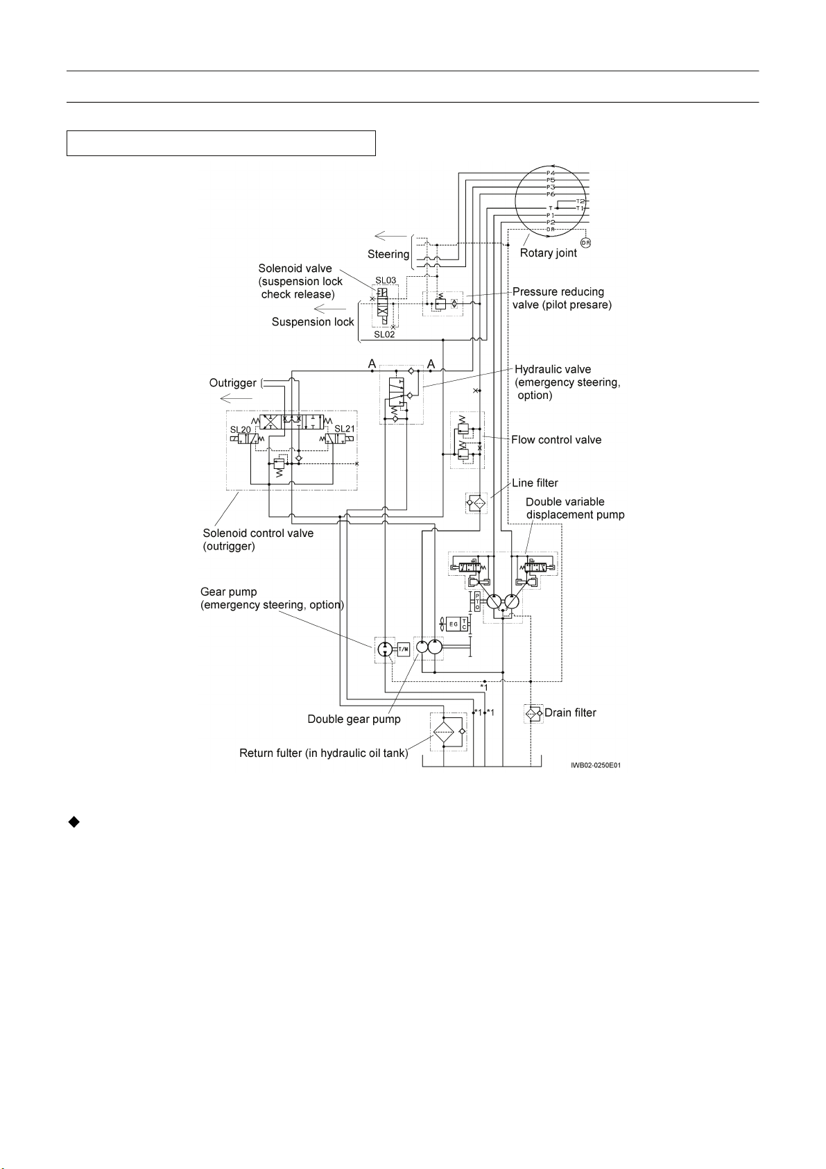
1. General
Hydraulic Circuit for Carrier (for Europe)
[NOTICE]
Emergency steering and steering pump low
pressure warning are standard equipment for
Europe.
1. The hydraulic power for this crane is generated by
the double variable displacement pump, double
gear pump, and gear pump for the emergency
steering circuit.
2. The double variable displacement pump supplies
oil to the circuits of elevating, telescoping, main
winch, and auxiliary winch. This double variable
displacement pump is driven only when the PTO
switch is turned on.
3. The double gear pump supplies oil to the circuits
of outrigger,steering, swing, pilot pressure, jibset,
air conditioner (option), and oil cooler.
4. The gear pump and the hydraulic valve in the
emergency steering circuit are standard. They are
provided for the case when the double gear pump
malfunctions.
1
WB02-0280E
Page 22
B-1 B-1
Hydraulic Power Generating System
Hydraulic Circuit for Carrier (for General Export)
[NOTICE]
If the machine is not equipped with the optional
emergency steering, two points "A" are directly
joined and three portions "*1" are plugged.
1. The hydraulic power for this crane is generated by
the double variable displacement pump, double
gear pump, and optional gear pump for the
emergency steering circuit.
2. The double variable displacement pump supplies
oil to the circuits of elevating, telescoping, main
winch, and auxiliary winch. This double variable
displacement pump is driven only when the PTO
switch is turned on.
3. The double gear pump supplies oil to the circuits
of outrigger,steering, swing, pilot pressure, jibset,
optional air conditioner, and oil cooler.
4. The gear pump and the hydraulic valve in the
emergency steering circuit are optional. They
are provided for the case when the double gear
pump malfunctions.
2
WB02-0280E
Page 23
B-1 B-1
Hydraulic Power Generating System
Hydraulic Circuit for Crane
Applicable serial No.
:545520 ~
1
△
[NOTICE]
If the machine is not equipped with the optional air
conditioner, two points "B" are directly joined.
Circuits for elevating, telescoping, main and auxiliary
winches
1. The hydraulic oil provided from the pumps is
controlled (onloaded/unloaded) by the solenoid
valve for automatic stop. This solenoid valve for
automatic stop is switched by the AML output to
control the vent ports of the relief valve (elevating,
telescoping) and the relief valve (main winch,
auxiliary winch). When the PTO switch is turned
on, the solenoid valve for automatic stop is shifted,
making the condition of this circuit onloaded.
2. The pressurized oil delivered through the P1 port
of the rotary joint is supplied to the circuits for the
main winch and the auxiliary winch.
The pressurized oil delivered through the P2 port
is provided to the circuits for elevating and
telescoping. This oil, however, is supplied to the
circuits for the main winch and the auxiliary winch
while neither elevating nor telescoping operation
is done.
3
WB02-0280E
Page 24

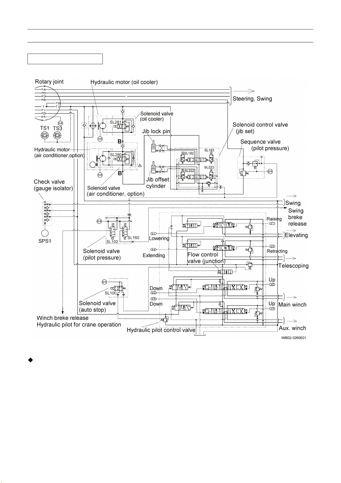
B-1. B-1.
Hydraulic Power Generating System
Circuit for pilot pressure, jibset, air conditioner(option),
and oil cooler
1. The pressurized oil delivered through the P6 port
of the rotary joint is supplied to these circuits.
Pressurized oil reduced by the sequence valve is
supplied to the circuit for the pilot pressure.
2. The pilot pressure is supplied to the swing brake
release circuit, main winch brake release circuit,
auxiliary winch brake release circuit, and pilot
circuits for crane operations.
3. The pressurized oil delivered through the
sequence valve is supplied to the circuits for the
jibset, air conditioner(option), and oil cooler.
4
WB02-0280E
Page 25
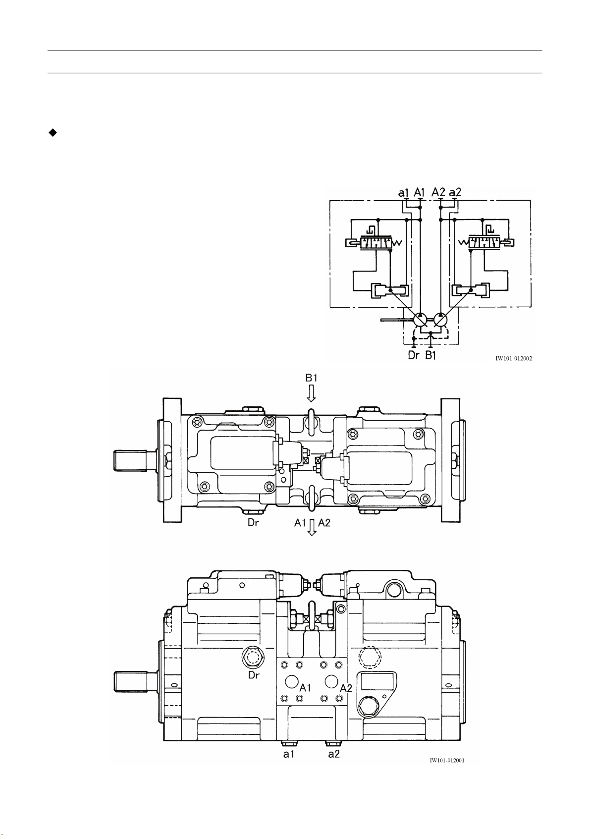
B-2 B-2
Hydraulic Pump (Double Variable Displacement Pump)
B-2 Hydraulic Pump (Double Variable Displacement Pump)
[NOTICE]
There is a case that the appearance and so on differ from the parts for this machine. Although there is not so
much difference in functions and disassembly procedures, make sure of the serial number of this machine and
the part sales unit described in the parts catalog before starting disassembling operations.
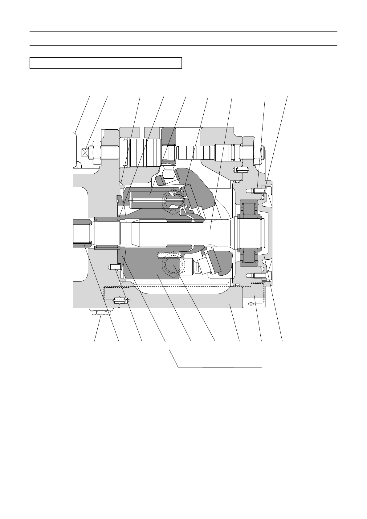
1. Structure
This pump is a variable displacement piston pump.
The angle of the swash plate is controlled by the regulator.
5
W101-0272E
Page 26
B-2 B-2
Hydraulic Pump (Double Variable Displacement Pump)
Main body
Apply adhesive (No. 1305N of Threebond make)
532732789535808
953
886
Apply (Sealub L101)
to the oil seal surface
circumferential
111.Drive shaft (F)
113.Drive shaft (R)
114.Spline coupling
123.Roller bearing
124.Needle bearing
127.Bearing spacer
141.Cylinder block
151.Piston
152.Shoe
153.Set plate
156.Spherical bush
157.Cylinder spring
211.Shoe plate
717
406
774
111
824
261
127
123
710
251
490 312 466
212 211 153 156 157 314
Valve plate for counter clockwise rotation
212.Swash plate
214.Tilting bush
251.Support
261.Seal cover (F)
262.Seal cover (R)
271.Pump casing
312.Valve block
313.Valve plate (R)
314.Valve plate (L)
401.Hex. socket head bolt
406.Hex. socket head bolt
466.Plug
467.Plug
Thread size and tightening torque
Sign / Port Thread size
Tightening torque
N-m ft-lbf
401 M16 240 177
406 M6 12 8.8
466 G1/4 36 26.5
467 G1/2 110 81
490 NPTF1/16 8.8 6.5
531
792
490.Plug
531.Tilting pin
532.Servo piston
534.Stopper (L)
535.Stopper (S)
548.Feed back pin
702.O-ring
710.O-ring
717.O-ring
719.O-ring
724.O-ring
725.O-ring
728.O-ring
901724534702214548
954 719 124 151 152 113 406 710
725
114 885
313 141
467
271 401 262
728
Valve plate for clockwise rotation
732.O-ring
774.Oil seal
789.Backup ring
792.Backup ring
808.Nut
824.Snap ring
885.Valve plate pin
886.Spring pin
901.Eye bolt
953.Hex. socket set screw
954.Set screw
981.Name plate
983.Pin
Sign / Port Thread size
Tightening torque
N-m ft-lbf
531,532 M20x1.5 240 177
808 M16 130 96
IW101-0270E01
6
W101-0272E
Page 27

B-2 B-2
Hydraulic Pump (Double Variable Displacement Pump)
Enlarged view of the main body (the left side)
Apply (Shealub L101)
to the oil seal surface circumferential
532732789535808
953
886
717
406
774
Apply adhesive (No. 1305N of Threebond make)
792
531
724534702214548
111
824
261
127
123
710
251
490 212 211 153 156 157
Valve plate for counter clockwise rotation
314
312
IW101-0270E02
7
W101-0272E
Page 28
B-2 B-2
Hydraulic Pump (Double Variable Displacement Pump)
Enlarged view of the main body (the right side)
901
954 719 124 151 152 113 406 710
466
114 885
313
141
725
Valve plate for clockwise rotation
8
467
728
W101-0272E
271 401 262
IW101-0270E03
Page 29
B-2 B-2
Hydraulic Pump (Double Variable Displacement Pump)
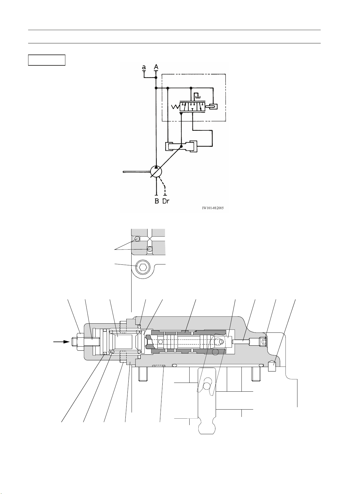
Regulator
Z
962
412
924 627 701801
624 651
652 621 496 887
629402625728
724
9
W101-0272E
IW101-012004
Page 30
B-2 B-2
Hydraulic Pump (Double Variable Displacement Pump)
413 496 897 601
755
614
708
402.Hex. socket head bolt
412.Hex. socket head bolt
413.Hex. socket head bolt
496.Plug
601.Casing
611.Feedback lever
Thread size and tightening torque
Sign / Port Thread size
402 M6 12 8.8
412,413 M8 29 24.1
496 NPTF1/16 8.8 6.5
614 G1/4 36 26.5
801 M8 17 12.5
614.Center plug
621.Compensator piston
624.Spring seat
625.Compensator spring
627.Spring seat
629.Spring case
View Z
651.Sleeve
652.Spool
701.O-ring
708.O-ring
724.O-ring
728.O-ring
Tightening torque
N-m ft-lbf
611
IW101-012006
755.O-ring
801.Nut
887.Pin
897.Pin
924.Hex. socket set screw
962.Steel ball
10
W101-0272E
Page 31

B-2 B-2
Hydraulic Pump (Double Variable Displacement Pump)
2. Theory of operating of regulator section
11
W101-0272E
Page 32

B-2 B-2
Hydraulic Pump (Double Variable Displacement Pump)
Hydraulic oil (P) from the pump flows to areas A
and B shown in Figs. 1 and 2 via the path in the
regulator casing.
The oil also flows to small-diameter end H of the
servo piston.
The oil flowing to area A applies leftward pressure
to the compensation piston.
When the pump pressure is below a certain level,
the spool does not move because the leftward
force of the compensation piston on the spool is
less than the pressure of the compensation spring.
In this situation, the seating area C closes and the
seating area E opens. Therefore the oil at the
servo piston’s large-diameter end G flows out
12
W101-0272E
Page 33

B-2. B-2.
Hydraulic Pump (Double Variable Displacement Pump)
from the port D to the drain line via the spool.
Then the servo piston’s large-diameter end G is
pushed by the pressure exerted on the
small-diameter end H, to stay in the maximum
discharge rate position.
When the pump pressure exceeds the 1st turning
point (P1 in Fig. 3), the leftward force of the
compensation piston on the spool overcomes the
pressure of the compensation spring and the
spool is moved to the left. As a result, seating
area E closes, and seating area C opens. The
hydraulic oil in area B flows to the servo piston’s
large-diameter end G via the port D pushing the
servo piston to the right decreasing the discharge
flow rate. The rightward movement of the servo
piston is transferred to the feedback lever via the
fulcrum J . The feedback lever revolves around
the pin on the top of the fulcrum plug. A pin (A) is
inserted in both the end of the feedback lever and
the hole of the sleeve. When the feedback lever
revolves, the sleeve moves to the left, and seating
areas C and E open where the Hydraulic powers
of the small and large-diameter ends of the servo
piston are balanced. When the pump pressure
decreases, the compensation spring pushes back
the spool, causing seating area C to close and
seating area E to open. The hydraulic oil at the
servo piston’s large-diameter end G is discharged
into the drain line, causing the servo piston to
move the left, increasing the discharge rate. The
movement of the servo piston is transferred to the
sleeve via the feedback lever, and seating areas
C and E open or close so that the servo piston,
under the pressures on both ends, follows the
movement of the spool.
As explained above, the discharge rate of the
pump is controlled by the balance of pressure on
the spool, the pressure setting compensation
spring, and the balance of pressure on the large
and small-diameter ends of the servo piston. The
maximum and minimum discharge rates are set
by adjustment screws 954 and 953, respectively.
The 1st turning point is set by the adjustment
screws. Gradients of the pressure discharge lines
are determined by the spring constant.
3. Air bleeding procedure
Refer to “Air Bleeding Procedure” in chapter Y.
366-533-50001
366-540-20000
0
△
0
△
13
W101-0272E
Page 34

B-3 B-3
Hydraulic Pump (Double Gear Pump)
B-3 Hydraulic Pump (Double Gear Pump)
[NOTICE]
There is a case that the appearance and so on differ from the parts for this machine. Although there is not so
much difference in functions and disassembly procedures, make sure of the serial number of this machine and
the part sales unit described in the parts catalog before starting disassembling operations.
1. Structure
123
IW101-013001
1.Gear pump assy 2.Connecting section 3.Gear pump assy
14
W101-0131E
Page 35

B-3 B-3
Hydraulic Pump (Double Gear Pump)
Gear pump assy-1
18 19 17 16 2 8,9 1 7 313
6,10
12
1.Body
2.Bearing box
3.Bearing box
6.Front cover
Connecting section-2
7.Side plate
8.Backup ring
9.Rubber string
10.Hex. socket head bolt
2 1 4
314215
IW101-013002
12.O-ring
13.Drive gear
14.Driven gear
15.Rear cover
3
16.Dowel pin
17.Oil seal
18.Oil seal
19.Retaining ring
IW101-013004
1.Coupling 2.O-ring 3.Dowel pin 4.Hex. socket head bolt
15
W101-0131E
Page 36

B-3. B-3.
Hydraulic Pump (Double Gear Pump)
Gear pump assy-3
13 16 2 8,9 1 7 3
6,10
12
1.Body
2.Bearing box
3.Bearing box
6.Front cover
7.Side plate
8.Backup ring
9.Rubber string
10.Hex. socket head bolt
2. Air bleeding procedure
Refer to “Air Bleeding Procedure” in chapter Y.
314215
IW101-013003
12.O-ring
13.Drive gear
14.Driven gear
15.Rear cover
16.Dowel pin
0
366-533-00000
366-519-00000
366-531-70000
16
W101-0131E
△
△
△
0
0
Page 37

B-4. B-4.
Hydraulic Power Generating System
B-4 Hydraulic Pump (Gear Pump, Emergency Steering)
[NOTICE]
There is a case that the appearance and so on differ from the parts for this machine. Although there is not so
much difference in functions and disassembly procedures, make sure of the serial number of this machine and
the part sales unit described in the parts catalog before starting disassembling operations.
1. Structure
25 3 21
AB
C-C
23 13 21 1 4 22 32 31
12 5 11 22 2
C
D
C
IW101-014001
1.Front cover
2.Body
3.Drive gear
4.Driven gear
Thread size and tightening torque
Sign / Port Thread size
A, B G3/4 62 - 75 46 - 56
D G1/4 24 - 29 17 - 22
31 M10 48 - 51 35 - 38
5.Side plate
11.Gasket
12.Gasket
13.Oil seal
21.Bush (front cover)
22.Bush (body)
23.Retaining ring
25.Steel ball
Tightening torque
N-m ft-lbf
31.Hexagon socket head bolt
32.Plain washer
366-535-20000
△
2
17
W101-0142E
Page 38

B-5 B-5
Hydraulic Valve (Emergency Steering) (Option)
B-5 Hydraulic Valve (Emergency Steering) (Option)
[NOTICE]
There is a case that the appearance and so on differ from the parts for this machine. Although there is not so
much difference in functions and disassembly procedures, make sure of the serial number of this machine and
the part sales unit described in the parts catalog before starting disassembling operations.
1. Structure
T
C
P2
P1
B
A
IW123-016001
P3
Y
P1
P3
P2
X X
T
Thread size and tightening torque
Sign / Port Thread size
P1, P3 G1 196 145
P2, T G3/4 167 123
Tightening torque
N-m ft-lbf
18
W123-0261E
Y
IW123-0260E01
Page 39

B-5. B-5.
Hydraulic Valve (Emergency Steering) (Option)
Cross section along the line X-X, Y-Y
13 5 9 6 2 1
14
A
12
4
710
1.Body
2.Check valve
3.Spool
4.Check valve
B
Y-Y
5.Cover
6.Spring
7.Spring
8.Spring
11
3
8
9.O-ring
10.Plug
11.Plug
12.Plug
11
C
X-X
IW123-0260E02
13.Spring washer
14.Hexagon socket head bolt
0
366-406-60000
19
W123-0261E
△
Page 40

B-6. B-6.
Flow Control Valve
B-6 Flow Control Valve
[NOTICE]
There is a case that the appearance and so on differ from the parts for this machine. Although there is not so
much difference in functions and disassembly procedures, make sure of the serial number of this machine and
the part sales unit described in the parts catalog before starting disassembling operations.
1. Structure
PB
7
4
T
1
PA
IW114-0130E02
PA
T
PB
IW114-0130E01
1.Valve body
2.Spool
3.Spring
4.Plug
Thread size and tightening torque
Sign / Port Thread size
5.Plug
6.O-ring
Tightening torque
N-m ft-lbf
2
3
5
6
IW114-0130E03
7.Relief valve assy
PA G3/4 167 123
T, PB G1/2 98 72
0
366-104-20000
20
W114-0132E
△
Page 41

B-7. B-7.
Pressure Reducing Valve (Pilot Pressure)
B-7 Pressure Reducing Valve (Pilot Pressure)
[NOTICE]
There is a case that the appearance and so on differ from the parts for this machine. Although there is not so
much difference in functions and disassembly procedures, make sure of the serial number of this machine and
the part sales unit described in the parts catalog before starting disassembling operations.
1. Structure
P
A1
DR A2
(*1)
IW120-0120E01
P
(*1) : Apply the thread locking agent (LOCTITE 270 or the equivalent)
A1
A2DR
12345678910
IW120-0120E02
1.Body
2.Spool
3.O-ring
4.Sleeve
5.Filter
6.O-ring
Thread size and tightening torque
Sign / Port Thread size
P G1/2 98 72
A1 G3/8 49 36
A2, Dr G1/4 29.4 22
7.Spacer
8.O-ring
9.Spring
Tightening torque
N-m ft-lbf
21
W120-0121E
10.Plug
366-054-90000
△
1
Page 42

r
B-8 B-8
Solenoid Control Valve (Outrigger)
B-8 Solenoid Control Valve (Outrigger)
[NOTICE]
There is a case that the appearance and so on differ from the parts for this machine. Although there is not so
much difference in functions and disassembly procedures, make sure of the serial number of this machine and
the part sales unit described in the parts catalog before starting disassembling operations.
1. Structure
AB
21
22
Sol. a1
R1
T
Connecto
(+): Red
IW112-015001
A
B
L
+ -
IW121-0542E01
(-): Blue
TP
L
L
P
G
Sol. b1
Sol. a1
R1
23
G
10 1 15
1.Body assy
10.P cover assy
15.T cover assy
21.Stud bolt
Thread size and tightening torque
Sign / Port Thread size
P, T, L
A, B G3/4 167 123
G G1/4 29.4 22
Sol. b1
IW112-015002
22.Nut
23.Spring washer
Tightening torque
N-m ft-lbf
G1 196 145
22
W112-0152E
Page 43

B-8 B-8
Solenoid Control Valve (Outrigger)
P cover assy
(illustrated as 10 on page 21)
1.Cover
2.O-ring
3.O-ring
4.Shim
5.Plug
6.Plug assy
7.Relief valve assy
5
7
R1
2
P
3
4
2
1
G
6
IW112-015003
23
W112-0152E
Page 44

B-8 B-8
Solenoid Control Valve (Outrigger)
Relief valve (illustrated as 7 on page 23)
P cover assy (2/2)
13 11 2 1 8 3 4 10 12 6 9 1475
P
T
1.Body
2.Plunger
3.Body
4.Poppet
5.Adjuster screw
6.Nut
7.Spring
8.Spring
9.Shim
10.O-ring
11.O-r ing
12.O-ring
IW112-011004
13.Backup ring
14.Cap
24
W112-0152E
Page 45

B-8 B-8
Solenoid Control Valve (Outrigger)
Body assy (1/2)
(illustrated as 1 on page 21)
1.Body
2.Spool
3.Plug
4.Plunger
5.Spring
6.O-ring
7.O-ring
8.O-ring
9.Shim
10.Pilot cover assy
10
Sol. a1
7
9
8
6
3
5
A
1
2
7
B
4
Sol. b1
IW112-015004
25
W112-0152E
Page 46

5
B-8. B-8.
Solenoid Control Valve (Outrigger)
Pilot cover assy (illustrated as 10 on page 21)
Body assy (2/2)
1.Cover
2.Plug
3.Spool
4.Spring
5.O-ring
6.Spring seat
7.Hexagon socket head bolt
8.Plug
9.Solenoid (DC24V)
10.Orifice
11.O-r ing
12.O-ring
13.Hexagon socket head bolt
14.Hexagon socket head bolt
15.Spring
8
14 6 10 15 11 13 12
1
8
7
9 5 3 4 2
IW112-01500
0
366-460-20000
26
W112-0152E
△
Page 47

B-9 B-9
Rotary Joint
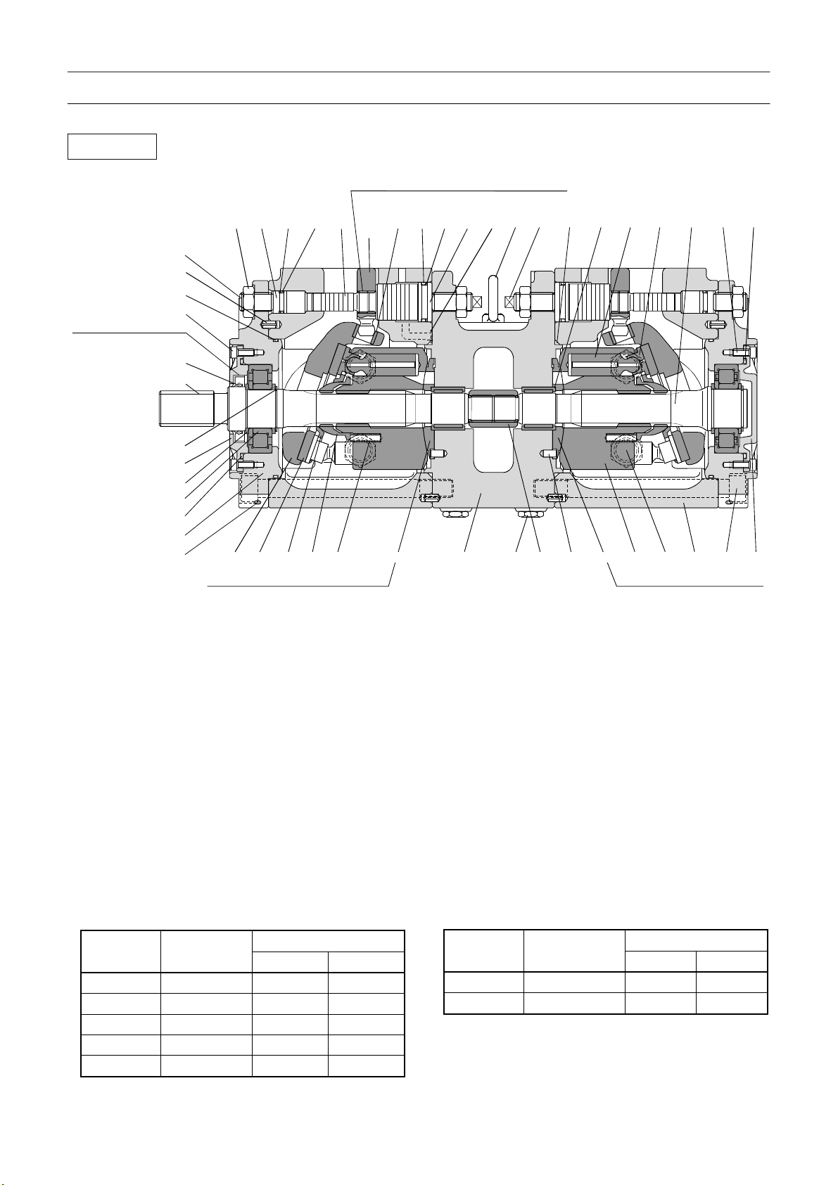
B-9 Rotary Joint
[NOTICE]
There is a case that the appearance and so on differ from the parts for this machine. Although there is not so
much difference in functions and disassembly procedures, make sure of the serial number of this machine and
the part sales unit described in the parts catalog before starting disassembling operations.
1. Structure
[NOTICE]
The parts marked with (*1) - (*10) require special attention for disassembling and assembling. The required
attention is described in the "Attention" on page 37.
27
W181-0440E
Page 48

B-9 B-9
Rotary Joint
Upper (view A)
Lower (view B)
28
W181-0440E
Page 49

B-9 B-9
Rotary Joint
1.Slip ring assy
2.Plain bearing
3.Packing
4.Ring seal
5.Body
6.Core
7.Shaft
8.Core
9.Plain bearing
Thread size and tightening torque
17 *1 (to secure the plate [18]) M8 11.8 – 13.7 9 - 10
21 *1 (to secure the slip ring ass’y [1]) M6 4.4 – 5.4 3.5 - 4
*1: Apply thread locking agent equivalent to THREE BOND 1401 to the threaded sections.
10.Support
11.Grease nipple
12.Plain bearing
13.Ring seal
14.Packing
15.Ring seal
16.Bolt
17.Flange bolt
18.Plate
Sign / port
16 *1 M12 74 - 82 55 - 61
25 *1 M8 23.5 – 27.5 17 - 20
29 - 16 - 24 12 - 17
19.Plug
20.Support
21.Flange bolt
22.Clamp
23.Nut
24.Plate
25.Hexagon socket head bolt
26.Ring seal
27.Pipe
Thread
size
Tightening torque
N-m ft-lbf
28.Fitting
29.Flare nut
30.Elbow fitting
31.Support
32.Grease nipple
33.O-ring
Hydraulic section
P1
P1’ Gauge
P2 Boom elevating, Boom telescoping
P2’ Gauge
P3 Swing, Steering
P4 Steering (left)
P5 Steering (right)
P6 Option
T1 Tank
T2 Tank
DR Drain
Sign / port Thread size
Winch
Outriggers pilot
Upper
Lower
Upper - - Lower G1/4 29.4 22
Upper G1/4 29.4 22
Lower - - Upper
Lower
Upper G1/4 29.4 22
Lower - - Upper G3/4 167 123
Lower G1 196 145
Upper
Lower
Upper
Lower
Upper
Lower
Upper
Lower
Upper G3/4 167 123
Lower - - Upper
Lower
G1 196 145
G1 196 145
G1/2 98 72
G1/2 98 72
G1/2 98 72
- - -
G1/2 98 72
Tightening torque
N-m ft-lbf
29
W181-0440E
Page 50

B-9 B-9
Rotary Joint
Pneumatic section
Tightening torque
N-m ft-lbf
A1 Air supply
A2 Service brake (primary)
A3 Service brake (secondary)
L.L.C. section
Sign / port Thread size
W1 Heater (IN)
W2 Heater (OUT)
Sign / port Thread size
Upper Rc3/8 49 - 69 36 - 51
Lower G1/4 29.4 22
Upper Rc3/8 49 - 69 36 - 51
Lower G1/4 29.4 22
Upper Rc3/8 49 - 69 36 - 51
Lower G1/4 29.4 22
Tightening torque
N-m ft-lbf
Upper
Lower
Upper
Lower
Rc3/8 49 - 69 36 - 51
Rc3/8 49 - 69 36 - 51
Attention
(*1): Face the "
(*2): Apply water-proof sealant equivalent to THREE
BOND 4101. Do not apply grease.
(*3): Apply thread locking agent equivalent to
THREE BOND 1401 to lock the threads.
(*4): Apply grease (EP2) when attaching.
(*5): Do not use an organic solvent.
(*6): Do not remove the shaft (8) from the core (7). It
is press-fit within the core.
(*7): To prevent rust, apply grease (EP2) when
assembling.
(*8): Tapped hole (2 places) for slinging. The
applicable thread size is M10.
・" mark toward FRONT.
(*9): The "
figure.
(*10): Do not use an organic solvent. The grease
grooves must be directed as shown below.
・" marks must be directed as shown in the
30
W181-0440E
Page 51

B-9 B-9
Rotary Joint
Slip ring Assy
21 28
22 20 31
31
C C
15
B
23
D
24
A
A
7
3
E
B
IW181-0260E03
27 26
2
D
19
30
25
E
T1
13
5
11
12
F
F
B-B
IW181-0260E04
10
4
12
8
29
6
3
9
7
16,17
18
1
P
A-A
P
IW181-0260E05
31
W181-0440E
IW181-0290E03
Page 52

B-9 B-9
Rotary Joint
36 14
E-E
C-C
IW181-0260E07
IW181-0260E09
25
24
23
1.Shaft
2.Ring set plate
3.Bearing
4.Ring
5.Ring
6.Ring set plate
7.U nut
8.Support
9.Stud bolt
D-D
IW181-0260E08
10.BH+CB
11.Spacer
12.Spacer
13.BH+CB
14.Support
15.Base
16.Dry lock nut
17.Coned disc spring
18.Guide
32,33
F-F
IW181-0260E10
19.O-ring
20.Potentiometer
21.Cover
22.Packing
23.Lever
24.Pin
25.Guide
26.Air breather
27.Hose joint
28.Hose band
29.Hexagon socket set screw
30.Machine screw
31.Bolt
32.Bolt
33.Spring washer
36.Hexagon socket head bolt
Thread size and tightening torque
Sign / port Thread size
16*1, T1*1 M6 4.9 3.6
31, 32, 36 M4 1.5 1.1
30 M3 0.63 0.5
*1:Apply LOCTITE 496 (strong quick-drying glue) to threaded sections.
Tightening torque
N-m ft-lbf
32
W181-0440E
Page 53

B-9 B-9
Rotary Joint
Wiring diagram
LOWER (Slip ring) UPPER (Brush holder)
G
3
2
2 1
34
12
78
56
11 12
910
14253
6
123
21
3
241
3
Connector
626 1 26
3223
627 12 27
628 11 28
629 10 29
630 9 30
20 8 20
21 7 21
22 6 22
4 5 24
615 4 15
16 3 16
618 2 18
19 1 19
12 6 12
13 5 13
614 4 14
8 3 8
9 2 9
10 1 10
907 3 7
911 2 111
5 1 25
17 3 17
6 1 6
2 2 5
1CC 4 3
1DD 3 4
1AA 2 1
1BB 1 2
Y
Y
Y
Y
Y
Y
Y
Y
Y
Y
Y
Y
Y
Y
Y
Y
Y
Y
Y
Y
Y
Y
Y
Y
W
W
W
W
W
W
Ring No.
W
1
3
2
Pot2
1
3
2
Pot1
1
30
29
28
27
26
25
24
23
22
21
20
19
18
17
16
15
14
13
Y
12
11
Y
10
9
8
7
6
5
4
3
2
1
R
B
B
Y
26 1 626
Y
23 2 3
Y
27 12 627
Y
28 11 628
Y
29 10 629
Y
30 630
Y
20 8
Y
21 7 21
Y
22 6 22
Y
Y
15 4 615
Y
16 3 16
Y
18 2 618
Y
19 1 19
Y
12 6 12
Y
13 5 13
Y
14 4 614
Y
8 3 8
Y
9 2 9
Y
10 1 10
Y
7 3 907
Y
11 2 911
Y
25 1 5
Y
17 1 17
W
6 2 6
W
5 3 2
W
3 4 1 C C
W
4 3 1 D D
W
1 2 1 A A
W
2 1 1 B B
6
5
4
9
20
424 5
36251
1 2
43
87
12 1 1
36251
321
12
132
21
65
10 9
3
4
4
4
:
Connector terminal No.
Mark No.
33
Silver-plating ring
W181-0440E
IW181-0290E04
Page 54

B-9. B-9.
Rotary Joint
2. Potentiometer
2.1 Adjustment
1. Install the potentiometer as shown in the figure
below. However, tighten the bolt for fixing the lever
lightly. (Do not fix the lever to the potentiometer
shaft because you must turn the potentiometer
shaft using the slotted screwdriver to adjust the
position of the shaft.)
Slotted screwdriver
Hexagon socket head bolt Potentiometer
3. Turn the potentiometer shaft using a slotted
screwdriver so that the resistance between the
upper terminals 1 and 2 is minimum between 1
ohm and 15 ohm. Leave the terminals (6 pieces)
of the potentiometer disconnected.
3
2
1
Terminal 3
Terminal 2
Terminal 1
Potentiometer
Slotted screwdriver
Upper terminals 1, 2 and 3
Bolt (Tighten lightly.)
Lever
IW181-0260E12
2. While keeping the stamp mark on the guide
oriented as shown in the figure below, adjust the
potentiometer as described in the following steps.
(If you adjust the potentiometer with the slip ring
assy installed on the crane, direct the boom
over-left to orient the stamp mark as shown in the
figure below.)
Slip ring assy
4. Remove the hexagon socket head bolts (4 pieces),
2.2 Soldering
1. After finishing the potentiometer adjustment,
Lower terminals 1, 2 and 3
IW181-0260E14
take out the potentiometer and fully tighten the
bolt for fixing the lever. Then install the
potentiometer and make sure that the resistance
between the upper terminals 1 and 2 is 15 ohm or
less.
remove the hexagon socket head bolts (4 pieces)
and take out the potentiometer. Then solder the
wiring to the terminals (6 pieces).
2. To insulate the terminals (6 pieces) from one
another, coat the terminal section with epoxy
Stamp mark
Guide
IW181-0260E13
34
adhesive (equivalent to 3M DP-420).
W181-0440E
346-305-71000
△
7
Page 55

B-10 B-10
Hydraulic Pilot Control Valve (Elevating, Telescoping, Winch)
B-10 Hydraulic Pilot Control Valve (Elevating, Telescoping, Winch)
[NOTICE]
There is a case that the appearance and so on differ from the parts for this machine. Although there is not so
much difference in functions and disassembly procedures, make sure of the serial number of this machine and
the part sales unit described in the parts catalog before starting disassembling operations.
1. Structure
35
W134-0271E
Page 56

B-10 B-10
Hydraulic Pilot Control Valve (Elevating, Telescoping, Winch)
C1 C2
Vent
Vent
(down) (down) (extending) (lowering)
b1 b2
b3 b4
T2
P2
a3 a4
Telescoping
(retracting)
T1
Aux. winch
(up)
B1 B2 B3 B4
A1 A2 A3 A4
a1 a2
Main winch
(up)
b3,b4
C3
a3,a4
Elevating
(raising)
P1
IW134-0270E02
36
W134-0271E
Page 57

B-10 B-10
Hydraulic Pilot Control Valve (Elevating, Telescoping, Winch)
Thread size and tightening torque
Sign / port Thread size
C1,C2,C3,a1,a2,a3,a4,b1,b2,b3,b4,Vent G1/4 29.4 22
A3,B3,A4,B4 G3/4 167 123
P1,P2,A1,B1,A2,B2 G1 196 145
Tightening torque
N-m ft-lbf
37
W134-0271E
Page 58

B-10 B-10
Hydraulic Pilot Control Valve (Elevating, Telescoping, Winch)
Cross section of whole body
BA
Aux. winch
Main winch
BA
14 13
Telescoping
Elevating
IW134-011012
38
W134-0271E
Page 59

B-10 B-10
Hydraulic Pilot Control Valve (Elevating, Telescoping, Winch)
1
C
12
・
8
C
Aux. winch
D
D
Main winch
12
・
9
E
2
F
3
Telescoping
E
F
G
4 7 16
A-A
Elevating
IW134-0270E03
G
39
W134-0271E
Page 60

B-10 B-10
Hydraulic Pilot Control Valve (Elevating, Telescoping, Winch)
Aux. winch
Main winch
515 6
1.Winch selector valve
2.Telescoping selector valve
3.Elevating selector valve
4.End cover
5.O-ring
6.O-ring
7.Hex. socket head bolt
8.Main relief valve
B-B
9.Main relief valve
12.Hex. socket head bolt
13.Plug
14.O-ring
Telescoping
Elevating
IW134-011004
15.Plug
16.Eye bol
Thread size and tightening torque
Sign / port Thread size
7 M12 57 - 59 42 - 43
12 M10 44 - 49 32.5 - 36
13 G1/4 24.5 - 29.4 18 - 22
15 - 10 - 12 7 - 9
Tightening torque
N-m ft-lbf
40
W134-0271E
Page 61

B-10 B-10
Hydraulic Pilot Control Valve (Elevating, Telescoping, Winch)
Winch selector valve
6242019 2122 1
25,24,23,13
18 17 15 28 27 26 28 14
Overload relief valve
9 8 12,23,24,25
7
11 10
30
29
16,17
C-C (Aux. winch) , D-D (Main winch)
18 17 15 28 27 26 28 16,175
IW134-0270E04
1
Main relief valve
E-E
41
W134-0271E
IW134-0110E07
Page 62

B-10 B-10
Hydraulic Pilot Control Valve (Elevating, Telescoping, Winch)
1.Winch selector valve body
2.Spool (main,aux. winch)
3.--------------------------------
4.Flow control valve
(main winch), (aux. winch)
5.Flow control valve (junction)
6.O-ring
7.Spring seat
Thread size and tightening torque
Sign / port Thread size
Overload relief valve
(Main winch), (Aux. winch)
*1: Apply LOCTITE 242 (thread locking agent) to threaded sections.
*2: Apply LOCTITE 270 (thread locking agent) to threaded sections.
8.Return spring
9.Return spring
10.Spring seat
11.Spool end
12.Pilot cover
13.Pilot cover
14.Orifice
15.Spring (flow control valve)
11*1 - 18 - 20 13 - 14
14*2
30*1 M8 12 - 14 8.5 - 10
16 M33 98 - 118 72 - 87
18 - 98 - 118 72 - 87
21 - 78.5 - 88.3 58 - 65
23 M8 27.5 - 29.4 20 - 22
26 G 3/8
28 -
16.Plug
17.O-ring
18.Spring retainer
(flow control valve)
19.Check valve
20.Spring (check valve)
21.Plug (check valve)
22.O-ring
Tightening torque
N-m ft-lbf
M27×1.5 78 - 88 58 - 65
M6 5 - 6 3.5 - 4.5
39.2 - 49
10 - 12 7 - 9
23.Hex. socket head bolt
24.Plain washer
25.Spring washer
26.Plug
27.O-ring
28.Plug
29.Steel ball
30.Hex. socket set screw
29 - 36
42
W134-0271E
Page 63

B-10 B-10
Hydraulic Pilot Control Valve (Elevating, Telescoping, Winch)
Telescoping selector valve
3029524 3 22 21 23 24 1
Overload relief valve
11 10
27,26,25,13
6 19,20 18 17 28 14 16 15
F-F (Telescoping)
1.Telescoping selector valve
body
2.Spool (telescoping)
3.Flow control valve
(telescoping)
4.Steel ball
5.Hex. socket set screw
6.O-ring
Thread size and tightening torque
Sign / port Thread size
Overload relief valve (Telescoping) M27×1.5 77 - 88 58 - 65
*1: Apply LOCTITE 242 (thread locking agent) to threaded sections.
*2: Apply LOCTITE 270 (thread locking agent) to threaded sections.
7.Spring seat
8.Return spring
9.Return spring
10.Spring seat
11.Spool end
12.Pilot cover
13.Pilot cover
14.Steel ball
5*1 M8 12 - 14 8.5 - 10
11*1 - 18 - 20 13 - 14
15*1 - 18 - 20 13 - 14
17*2 M6 5 - 6 3.5 - 4.5
19 M33 98 - 118 72 - 87
23 - 78.5 - 88.3 58 - 65
25 M8 27.5 - 29.4 20 - 22
28 - 10 - 12 7 - 9
29 G3/4 78.5 – 88.3 58 - 65
15.Plug (shuttle valve)
16.O-ring
17.Orifice
18.Spring (flow control valve)
19.Plug
20.O-ring
21.Check valve
22.Spring (check valve)
8
7 9 12,25,26,27
19,20
IW134-0270E03
23.Plug (check valve)
24.O-ring
25.Hex. socket head bolt
26.Plain washer
27.Spring washer
28.Plug
29.Plug
30.O-ring
Tightening torque
N-m ft-lbf
43
W134-0271E
Page 64

B-10 B-10
Hydraulic Pilot Control Valve (Elevating, Telescoping, Winch)
Elevating selector valve
22,21,20,13
6 16,17 15 14 23
19185 4 18 19 12
G-G (Elevating)
Overload relief valve
11 10
8
7 9 12,20,21,22
3
16,17
IW134-0110E09
1.Elevating selector valve body
2.Spool (elevating)
3.Flow control valve (elevating)
4.Steel ball
5.Hex. socket set screw
6.O-ring
Thread size and tightening torque
Sign / port Thread size
Overload relief valve
(Elevating)
*1: Apply LOCTITE 242 (thread locking agent) to threaded sections.
*2: Apply LOCTITE 270 (thread locking agent) to threaded sections.
7.Spring seat
8.Return spring
9.Return spring
10.Spring seat
11.Spool end
12.Pilot cover
5*1 M8 12 - 14 8.5 - 10
11*1 - 18 - 20 13 - 14
14*2 M6 5 - 6 3.5 - 4.5
16 M33 98 - 118 72 - 87
18 G3/4 78.5 - 88.3 58 - 65
20 M8 27.5 - 29.4 20 - 22
23 - 10 - 12 7 - 9
13.Pilot cover
14.Orifice
15.Spring (flow control valve)
16.Plug
17.O-ring
18.Plug
Tightening torque
N-m ft-lbf
M27×1.5 78 - 88 58 - 65
19.O-ring
20.Hex. socket head bolt
21.Plain washer
22.Spring washer
23.Plug
44
W134-0271E
Page 65

B-10 B-10
Hydraulic Pilot Control Valve (Elevating, Telescoping, Winch)
Main relief valve
(Main winch, Aux. winch), (Elevating, Telescoping)
1.Socket
2.Valve
3.Spring
4.O-ring
5.Backup ring
20 19
6.O-ring
7.Packing
8.Body
9.O-ring
10.Cap nut
1413121110987632154
15
16
17
18
P
T
11.Adjust screw
12.O-ring
13.Nut
14.Body
15.Spring
IW134-011010
16.Valve
17.Valve seat
18.O-ring
19.Seal lead
20.Tie up wire
Thread size and tightening torque
Sign / port Thread size
1 - 28.4 - 30.4 21 - 22.4
10 M14×1 18.6 - 20.6 13.7 - 15.2
13 M14×1 18.6 - 20.6 13.7 - 15.2
14 - 38.2 - 40.2 28.2 - 29.6
Tightening torque
N-m ft-lbf
45
W134-0271E
Page 66

B-10. B-10.
Hydraulic Pilot Control Valve (Elevating, Telescoping, Winch)
Overload relief valve
(Main winch), (Aux. winch), (Elevating), (Telescoping)
6754231981013121114
P
16 15
1.Socket
2.Valve
3.O-ring
4.Spring
Thread size and tightening torque
Sign / port Thread size
1 - 18.6 - 20.6 13.7 - 15.2
8 M27×1.5 78.5 - 88.3 58 - 65
13 M14×1 18.6 - 20.6 13.7 - 15.2
14 M14×1 18.6 - 20.6 13.7 - 15.2
5.Valve seat
6.O-ring
7.O-ring
8.Body
T
IW134-011011
9.Valve
10.Spring
11.Adjust screw
12.O-ring
Tightening torque
N-m ft-lbf
13.Nut
14.Cap nut
15.Tie up wire
16.Seal lead
0
366-405-40000
46
W134-0271E
△
Page 67

B-11 B-11
Sequence Valve (Pilot Pressure)
B-11 Sequence Valve (Pilot Pressure)
[NOTICE]
There is a case that the appearance and so on differ from the parts for this machine. Although there is not so
much difference in functions and disassembly procedures, make sure of the serial number of this machine and
the part sales unit described in the parts catalog before starting disassembling operations.
1. Structure
Thread size and tightening torque
Sign / port Thread size
P, V G1/2 98 72
Dr G3/8 49 36
Pi, G G1/4 29.4 22
Tightening torque
N-m ft-lbf
47
W122-0113E
Page 68

B-11 B-11
Sequence Valve (Pilot Pressure)
Cross section along the line A-A
(back pressure regulating valve, pressure reducing valve)
1.Body
2.Filter
3.Filter retainer
4.Back pressure regulating valve
5.Pressure reducing valve
6.Hexagon socket head bolt
7.Plug
8.O-ring
9.Plug
Thread size and tightening torque
Sign / port Thread size
3 G1/2 9.81 - 11.8 7.2 - 8.7
6 M6 9.81 - 10.8 7.2 - 8
5
4
Tightening torque
N-m ft-lbf
6
A-A
123
IW122-0112E01
Back pressure regulating valve
(illustrated as 4 in the cross section along the line A-A)
12673485
1.Spring cover
2.Stopper
3.Piston
4.Valve
5.Socket
6.Spring
7.O-ring
8.O-ring
Thread size and tightening torque
Sign / port Thread size
1 M24×1.5 58.8 – 68.6 43.4 – 50.6
Tightening torque
N-m ft-lbf
IW122-011004
48
W122-0113E
Page 69

B-11. B-11.
Sequence Valve (Pilot Pressure)
Pressure reducing valve
(illustrated as 5 in the cross section along the line A-A)
1.Body
2.Spool
3.O-ring
4.Plug
7
91
11 10 8 6 3 5 12 2 13
5.Spring seat
6.Spring
7.Adjust screw
8.Body
9.O-ring
10.Nut
11.Cap nut
12.O-ring
4
IW122-011005
13.O-ring
0
366-038-80000
366-060-30000
49
W122-0113E
△
△
0
Page 70

B-12 B-12
Solenoid Valve (Pilot Pressure)
B-12 Solenoid Valve (Pilot Pressure)
[NOTICE]
There is a case that the appearance and so on differ from the parts for this machine. Although there is not so
much difference in functions and disassembly procedures, make sure of the serial number of this machine and
the part sales unit described in the parts catalog before starting disassembling operations.
1. Structure
A2
T
A1
IW121-067001
P
701
Connector
IW121-0671E01
171
101.Casing
171.Hexagon socket head bolt
701.Solenoid valve (DC24V)
Thread size and tightening torque
Sign / port Thread size
P,T,A1,A2 G1/4 34 - 38 25 - 28
171 M5 6 - 8 4.5 - 6
T1 M8 26 - 32 20 - 24
T
A2 A1
P
101
T
1
IW121-067002
Tightening torque
N-m ft-lbf
50
W121-0672E
Page 71

3
B-12. B-12.
Solenoid Valve (Pilot Pressure)
Solenoid valve assy
31 1
PAT
312 361 362 363 861 801 802
311.Spool
312.Sleeve
324.Spring
326.Retaining ring
361.O-ring
362.O-ring
Thread size and tightening torque
Sign / port Thread size
802 M6 6.9 - 7.9 5.1 - 5.8
326 324
IW121-06700
363.O-ring
801.Solenoid valve
802.Seal nut
Tightening torque
N-m ft-lbf
861. O-ring
0
367-401-00000
51
W121-0672E
△
Page 72

B-13 B-13
Solenoid Control Valve (Jib Set)
B-13 Solenoid Control Valve (Jib Set)
[NOTICE]
There is a case that the appearance and so on differ from the parts for this machine. Although there is not so
much difference in functions and disassembly procedures, make sure of the serial number of this machine and
the part sales unit described in the parts catalog before starting disassembling operations.
1. Structure
CO
A2
B2
PP
GP T
Connector
+ -
IW121-0542E01
IW112-0220E01
(+) : Red
(-) : Black
A1
B1
52
W112-0222E
Page 73

B-13 B-13
Solenoid Control Valve (Jib Set)
33
C・O
31
21
A
B
C
3218
D
B2 B1
A2 A1
T
P
OUT
IN
OUT
C
33
33
D
P. P
A
B
33
27,38
18.Name plate
21.Tigh rod
27.Plug
29.Hexagon socket head bolt
Thread size and tightening torque
Sign / port Thread size
P, T G1/2 98 72
A1, B1, A2, B2 G3/8 49 36
C•O G1/2 98 72
P•P G1/4 29.4 22
31.Nut
32.Ribbet screw
33.Ball
38.O-ring
Tightening torque
N-m ft-lbf
29
P.P
33
IW112-0220E02
53
W112-0222E
Page 74

B-13 B-13
Solenoid Control Valve (Jib Set)
28 34 19 38 23 27 33
6.Collar
7.Spring folder
8.Plug
9.Spring
16.Solenoid
19.Body
20.Spring
22.Spring
23.Filter
25.Spool end
27.Plug
28.Hexagon socket head bolt
33.Ball
34.O-ring
35.O-ring
37.O-ring
38.O-ring
44.O-ring
16
6
35
8
7
22
25
44
35
33
35
28
16 34 19 38 27 23 20
A-A
IW112-0220E03
33
35
37
8
9
33
54
W112-0222E
Page 75

4
4
B-13 B-13
Solenoid Control Valve (Jib Set)
14.Spol
15.Housing
17.Housing plunger
24.Housing
35.O-ring
43.O-ring
14
14
35
24
17
3
15
35
B-B
IW112-0220E0
55
W112-0222E
Page 76

B-13 B-13
Solenoid Control Valve (Jib Set)
T
P
C-C
IW112-0220E05
C O
D-D
56
IW112-0220E06
W112-0222E
Page 77

7
B-13. B-13.
Solenoid Control Valve (Jib Set)
Relief valve
42 12 2 41 1 40 10 4 30 3365131139
1.Spring
2.Needle valve
3.Nut
4.Gasket
5.Spring
10.Housing
11.Sle eve
12.Sleeve
13.Poppet
30.Screw
36.O-ring
39.O-ring
IW112-0220E0
40.O-ring
41.O-ring
42.O-ring
0
366-489-20000
57
W112-0222E
△
Page 78

B-14. B-14.
Pilot Check Valve (Jib Set)
B-14 Pilot Check Valve (Jib Set)
[NOTICE]
There is a case that the appearance and so on differ from the parts for this machine. Although there is not so
much difference in functions and disassembly procedures, make sure of the serial number of this machine and
the part sales unit described in the parts catalog before starting disassembling operations.
1. Structure
BA
DC
IW115-027001
765 34
B
A
DC
81 9210
X-X
11
IW115-027002
1.Body
2.Sleeve
3.Poppet
Thread size and tightening torque
Sign /port Thread size
A,B,C,D G1/4 29.4 22
4.Spring
5.Piston
6.O-ring
7.Backup ring
8.O-ring
9.O-ring
Tightening torque
N-m ft-lbf
58
W115-0271E
10.O-ring
11.Plug
12.Plug
366-241-40000
△
1
Page 79

B-15 B-15
Solenoid Valve (Oil Cooler)
B-15 Solenoid Valve (Oil Cooler)
[NOTICE]
There is a case that the appearance and so on differ from the parts for this machine. Although there is not so
much difference in functions and disassembly procedures, make sure of the serial number of this machine and
the part sales unit described in the parts catalog before starting disassembling operations.
1. Structure
4
bf
3
2
a
bf
1
ae
PA
TB
T1
e
P
B
A
T
IW121-025001
1.Solenoid valve assy 2.Body 3.Valve 4.Plug
Thread size and tightening torque
Sign / port Thread size
a, b, e, f G1/2 98 72
T1 M5 7 - 8 5 - 6
Tightening torque
N-m ft-lbf
59
W121-0253E
IW121-025002
Page 80

B-15. B-15.
Solenoid Valve (Oil Cooler)
Solenoid valve assy
Connector
(+): Red
+ -
(-): Blue
1.Body
2.Plug
3.Spool
T1
7.Spring seat
8.Square ring
9.O-ring
IW121-0542E01
3
AB
TT
P
12 9 1 15 8 7 11 2T2
IW121-025003
11.Spring
12.Solenoid (DC24V)
15.Hexagon socket head bolt
Thread size and tightening torque
Sign / port Thread size
2 - 44 - 49 32 - 36
15 M5 7 5
T1 - 39 - 49 29 - 36
T2 - 4.4 – 5.4 3 - 4
Tightening torque
N-m ft-lbf
60
W121-0253E
366-457-50000
△
1
Page 81

B-16. B-16.
Solenoid Valve (Oil Cooler)
B-16 Hydraulic Motor (Oil Cooler)
[NOTICE]
There is a case that the appearance and so on differ from the parts for this machine. Although there is not so
much difference in functions and disassembly procedures, make sure of the serial number of this machine and
the part sales unit described in the parts catalog before starting disassembling operations.
1. Structure
25 14 2 4 7 5 32 8 10 1 33 34 13
D
A,B
27 12 21 17 19 20 16 22 23 3
1.Front case
2.Rear case
3.Shaft
4.Cylinder block
5.Piston retainer
7.Spherical retainer
Thread size and tightening torque
Sign /port Thread size
A, B G3/8 64 47
D G1/4 40 30
21 M5 4 - 6 2.9 - 4.3
25 M8 34 - 39 25 - 29
34 M5 2 - 3 1.4 - 2.2
8.Spherical pin
10.Collar
12.Spring
13.Straight key
14.Plain washer
16.Oil seal
17.Needle bearing
19.Thrust roller bearing
20.Thrust plate
21.Hexagon socket head but
bolt
22.Ball bearing
Tightening torque
N-m ft-lbf
IW102-012001
23.Retaining ring
25.Hexagon socket head bolt
27.O-ring
32.Piston assy
33.Seal plate
34.Flat head machine screw
2. Air bleeding procedure
Refer to “Air Bleeding Procedure” in chapter Y.
61
W102-0122E
366-632-60000
366-631-10000
366-631-20000
△
△
△
0
0
0
Page 82

B-17. B-17.
Jib Lock Pin
B-17 Jib Lock Pin
[NOTICE]
There is a case that the appearance and so on differ from the parts for this machine. Although there is not so
much difference in functions and disassembly procedures, make sure of the serial number of this machine and
the part sales unit described in the parts catalog before starting disassembling operations.
1. Structure
1.Spring pin
2.plate
3.Plain bearing
4.Ring seal
*1 : Face the notch or the lip toward the pressurized side.
*2 : Apply sealant equivalent to three bond 1104.
Thread size and tightening torque
Sign / port Thread size
A, B G1/4 29.4 22
5.O-ring
6.Piston
7.Cylinder
8.Rod
Tightening torque
N-m ft-lbf
9.Rod cover
10.Plain bearing
11.O-r ing
12.Damper ring
13.Packing
14.Backup ring
15.Dust seal
0
360-531-60000
62
W180-0021E
△
Page 83

B-18. B-18.
Jib Offset Cylinder
B-18 Jib Offset Cylinder
[NOTICE]
There is a case that the appearance and so on differ from the parts for this machine. Although there is not so
much difference in functions and disassembly procedures, make sure of the serial number of this machine and
the part sales unit described in the parts catalog before starting disassembling operations.
1. Structure
1.Cylinder
2.Split pin
3.Nut
4.Piston
*1 : Face the notch or the lip toward the pressurized side.
Thread size and tightening torque
Sign / port Thread size
A, B G1/4 29.4 22
5.Plain bearing
6.O-ring
7.Rod
8.Rod cover
9.O-ring
10.Damper ring
11.packing
12.Backup ring
Tightening torque
N-m ft-lbf
13.Plate
14.Dust seal
15.---
16.Plain bearing
0
360-520-90000
63
W180-0031E
△
Page 84

B-19. B-19.
Check Valve (Gauge Isolator)
B-19 Check Valve (Gauge lsolator)
[NOTICE]
There is a case that the appearance and so on differ from the parts for this machine. Although there is not so
much difference in functions and disassembly procedures, make sure of the serial number of this machine and
the part sales unit described in the parts catalog before starting disassembling operations.
1. Structure
Hydraulic symbols
8254367
1
P3P2P1
IW116-012001
SP'
S
P1 P2 P3
Thread size and tightening torque
Sign / port Thread size
P1, P2, P3, P’ G 1/4 29.4 22
S
Mounting bolt M8 13 - 15 9.6 - 11.0
1. Body
2. Plug
3. Poppet
4. Spring
IW116-012002
Tightening torque
N-m ft-lbf
G 3/8 49.0 36
M18×1.5 127 - 147 93 - 108 TT-300XL-1 only
5. O-ring
6. Screw
64
W116-0123E
Remark
7. Plug
8. O-ring
366-244-50000
366-251-20000
△
△
1
0
Page 85

Contents
C-1 Outrigger System.............................1
1. General ...................................................... 1
C-2 Jack Cylinder....................................5
1. Structure .................................................... 5
C
C
Outrigger System
C-7 Solenoid Valve (Slide/Jack)
(NACHI)...................................10
1. Structure .................................................. 10
C-8 Check Valve (Outrigger Extending
Prevention).............................11
C-3 Pilot check Valve (Jack Cylinder
Retracting Prevention) ............ 6
1. Structure .................................................... 6
C-4 Extension Cylinder ..........................7
1. Structure .................................................... 7
C-5 Solenoid Valve (Slide/Jack)
(UCHIDA) .................................. 8
1. Structure .................................................... 8
C-6 Solenoid Valve (Slide / Jack)
(TOKIMEC) ...............................9
1. Structure ...................................................11
C-9 Outrigger Operation Box ...............12
1. Structure .................................................. 12
2. Connector diagram.................................. 13
3. Specifications........................................... 13
3.1 General .....................................................13
3.2 Bipolar toggle switch .................................13
3.3 Monopolar toggle switch ...........................13
3.4 Push switch...............................................13
3.5 Diode.........................................................13
3.6 Lamp assembly.........................................13
1. Structure .................................................... 9
i
Page 86

C-1 C-1
Outrigger System
C-1 Outrigger System
1. General
Hydraulic Circuit
1. The outrigger controls use the solenoid control
valve to select between extension or retraction for
each cylinder. The solenoid valve selects between
operation of the extension cylinder and the jack
cylinder.
2. During outrigger extension, the pressure oil from
the pump passes through the solenoid control
valve and solenoid valve to enter the cylinders.
3. At this time, back pressure is generated in the
return oil by the pilot check valve. The return oil
then passes through the solenoid control valve
and returns to the tank.
4. During outrigger retraction, the pressure oil
passes through the solenoid control valve and
pilot check valve, and operates on the retraction
side of the extension and jack cylinders. Only the
circuit of the cylinder selected by the solenoid
valve retracts.
5. The maximum puressure in the outrigger hydraulic
circuit is regulated by the relief valve.
1
WC02-0290E
Page 87

C-1 C-1
Outrigger System
Electric Circuit (Relay RF3, Solenoid Valve)
1. The solenoid valve (extending/retracting) and the
four solenoid valves (slide/jack) are switched
according to the outputs from the multiplex data
transmitter (lower). The outputs to the four
solenoid valves (slide/jack) are transmitted via the
relay RF3.
2
WC02-0290E
Page 88

C-1 C-1
Outrigger System
Electric Circuit For Europe
〔
〔
43〕WB
〔
62〕Y
〔
249〕RL
236〕YB
D50
D51
236A〕RY
〔
236B〕LY
〔
249A〕R
〔
〔 249B〕LR
45〕PB
〔
44〕WY
〔
42〕WR
〔
〔 41〕W
46〕WL
〔
0〕B
〔
D52
D53
249B〕LR
〔
46〕WL
〔
141B〕RL
〔
236B〕LY
〔
〔 62〕Y
43〕WB
〔
45〕PB
〔
44B〕RL
〔
〔 42〕WR
41B〕RW
〔
〔 0〕B
9
10
11
12
14
13
Gr
R
P
O
Sb
L
G
Y
Br
W
B
Relay
RF3
723651
Outrigger operation box
(Left side)
41〕W
〔
〔 44〕 WY
〔 46〕 WL
〔
0〕B
〔 44B〕 RL
〔 41B〕 RW
〔 141B〕 RL
236A〕RY
〔
〔 0〕 B
〔 561〕 R
106〕YW
〔
4
107〕YB
〔
8
〔 108〕YO
3
84
1210911
〔 109〕YG
7
+14
2
〔 110〕RW
-13
111〕RB
〔
6
112〕RL
〔
1
5
113〕RG
〔
5
8
14
13
12
9
Relay
RD5
Relay
RB8
Solenoid valve
(slide/jack)
560
〔
〕RY
Multiplex data transmitter
(Lower)
〔 249A〕R
46〕WL
〔
141A〕BR
〔
236A〕RY
〔
〔 62〕Y
43〕WB
〔
41〕W
〔
〔 42A〕WL
44〕WY
〔
45A〕LB
〔
B
〔 0〕
〔
〔
〔
〔
141〕RB
560〕RY
0〕B
561〕R
Gr
R
P
O
Sb
L
G
Y
Br
W
B
Relay
RB6
43〕WB
〔
〔
62〕Y
Solenoid valve
(extending/retracting)
561〕R
〔
236B〕LY
〔
0〕B
〔
141A〕BR
〔
42〕WR
〔
〔 45〕PB
46〕WL
〔
0〕B
〔
45A〕LB
〔
42A〕WL
〔
Outrigger operation box
(Right side)
Power supply
Relay
RB7
5
8
14
13
12
9
Relay
RD4
IWC02-0290E01
3
WC02-0290E
Page 89

C-1. C-1.
Outrigger System
[In case of for Europe only, the control outside the cab
is applied.]
1. The controls are located at the both sides of the
carreir.
2. You can extend or retract only the sliders in the
same side of the crane as the controls operated.
Relay RD5: Selector relay for left side [SLIDE]
RD5
relay coil
energized close jack
de-energized open slide
Relay RD4: Selector relay for right side [SLIDE]
RD4
relay coil
energized close jack
de-energized open slide
3. If the right and left controls are opetated
simultaneously, the switch pressed first becomes
activated.
Relay RB7: Power supply selector relay
(This contact [CLOSES] when right side ext./ret.
switch’s selection is selected before the left side
one)
Relay RB8: Power supply selector relay
(This contact [CLOSES] when left side ext./ret.
switch’s selection is selected before the right side
one)
a-contact selected operation
operates any
jacks
operates
left slide only
a-contact selected operation
operates any
jacks
operates
right slide only
4. The Lower outrigger controls cannot be used
while the upper outrigger controls are in use.
Relay RB6: Power supply control relay for both lower outrigger operation box.
outrigger ext./ret. operating
switch selection timing
lower is before upper de-energized close lower outrigger operation
upper is before lower energized open upper outrigger operation
RB6 relay coil b-contact priority
4
WC02-0290E
Page 90

C-2. C-2.
Jack Cylinder
C-2 Jack Cylinder
[NOTICE]
There is a case that the appearance and so on differ from the parts for this machine. Although there is not so
much difference in functions and disassembly procedures, make sure of the serial number of this machine and
the part sales unit described in the parts catalog before starting disassembling operations.
1. Structure
1.Cylinder
2.Rod
3.Bolt
4.Spring washer
5.Bolt
Thread size and tightening torque
Sign / port Thread size
3,5 M10 22 - 25 16 - 18
T1 M24 588 - 666 434 - 492
6.Stopper
7.Spring pin
8.Piston
9.Packing
10.Backup ring
11.O-r ing
12.Backup ring
13.O-ring
15.Rod cover assy
16.Packing
Tightening torque
N-m ft-lbf
5
W151-0112E
17.Backup ring
18.Dust seal
19.Damper ring
21.Backup ring
22.Plain bearing
360-302-90000
△
8
Page 91

C-3. C-3.
Pilot Check Valve (Jack Cylinder Retracting Prevention)
C-3 Pilot check Valve (Jack Cylinder Retracting Prevention)
[NOTICE]
There is a case that the appearance and so on differ from the parts for this machine. Although there is not so
much difference in functions and disassembly procedures, make sure of the serial number of this machine and
the part sales unit described in the parts catalog before starting disassembling operations.
1. Structure
9
AB
CD
CD
IW115-023001
5
4
67,8
2
1.Valve body
2.Plug
3.O-ring
Thread size and tightening torque
Sign / port Thread size
A G1/4 29.4 22
B G1/4 29.4 22
Mounting
bolt
4.Valve
5.Spring
6.Piston
M10 43 - 49 32 - 36
A
Tightening torque
N-m ft-lbf
B
IW115-0490E01
7.O-ring
8.Backup ring
9.O-ring
3
1
366-200-00000
△
1
6
W115-0491E
Page 92

C-4. C-4.
Extension Cylinder
C-4 Extension Cylinder
[NOTICE]
There is a case that the appearance and so on differ from the parts for this machine. Although there is not so
much difference in functions and disassembly procedures, make sure of the serial number of this machine and
the part sales unit described in the parts catalog before starting disassembling operations.
1. Structure
1.Cylinder
2.Nut
3.Seal ring
Thread size and tightening torque
Sign / port Thread size
A, B, C G3/8 49 36
D, E G1/4 29.4 22
2 M20 176 - 196 130 - 145
4.Piston
5.Rod
6.Rod cover
7.O-ring
8.Packing
9.Backup ring
Tightening torque
N-m ft-lbf
7
W153-0012E
10.Dust seal
360-424-20000
△
1
Page 93

r
C-5. C-5.
Solenoid Valve (Slide/Jack) (UCHIDA)
C-5 Solenoid Valve (Slide/Jack) (UCHIDA)
[NOTICE]
There is a case that the appearance and so on differ from the parts for this machine. Although there is not so
much difference in functions and disassembly procedures, make sure of the serial number of this machine and
the part sales unit described in the parts catalog before starting disassembling operations.
1. Structure
Connecto
AB
PT
IW121-026001
A
TT
B
P
+ -
IW121-0542E01
(+): Red
(-): Blue
1.Body
3.Spool
Thread size and tightening torque
Sign / port Thread size
15 M5 6.9 - 8.9 5.1 - 6.5
T1 - 3.9 - 4.9 2.9 - 3.6
T2 - 38.3 - 41.2 28.3 - 30.4
7.Spring seat
8.Square ring
11 9T27 3 8 15 1
IW121-026003
9.O-ring
11.Spring
Tightening torque
N-m ft-lbf
8
W121-0263E
12.Solenoid (DC24V)
15.Hex. socket head bolt
366-478-90000
△
1
Page 94

C-6. C-6.
Solenoid Valve (Slide/Jack) (TOKIMEC)
C-6 Solenoid Valve (Slide/Jack) (TOKIMEC)
[NOTICE]
There is a case that the appearance and so on differ from the parts for this machine. Although there is not so
much difference in functions and disassembly procedures, make sure of the serial number of this machine and
the part sales unit described in the parts catalog before starting disassembling operations.
1. Structure
Connector
AB
PT
IW121-026001
12
T
P T
A
B
1 2 3 4 5 6 7 8 9 10 11
Note: Install the centering washer (10) with its slit directed toward the body (7).
+ -
IW121-0542E01
(+): Red
(-): Black
IW121-027001
1.Nut
2.O-ring
3.Solenoid core (DC24V)
Thread size and tightening torque
Sign / port Thread size
1 - 8.8 - 10.8 6.5 - 8
3 - 18 - 22 13.3 - 16.2
Mounting bolt M5 6.9 - 7.8 5 - 6
4.Solenoid coil (DC24V)
5.Packing
6.O-ring
7.Body
8.O-ring
9.Spool
Tightening torque
N-m ft-lbf
9
W121-0273E
10.Centering washer
11.Spring
12.Spring pin
366-465-40000
△
1
Page 95

C-7. C-7.
Solenoid Valve (Slide/Jack) (NACHI)
C-7 Solenoid Valve (Slide/Jack) (NACHI)
[NOTICE]
There is a case that the appearance and so on differ from the parts for this machine. Although there is not so
much difference in functions and disassembly procedures, make sure of the serial number of this machine and
the part sales unit described in the parts catalog before starting disassembling operations.
1. Structure
Connector
AB
PT
IW121-026001
10 16
T T
P
AB
7 14 8 9 6 15 4 3 13 2 1
+ -
IW121-0542E01
(+): White
(-): Black
IW121-028001
1.Body
2.Spool
3.Retainer
4.Retainer
Thread size and tightening torque
Sign / port Thread size
7 - 5 - 7 3.7 - 5.1
Mounting bolt M5 6 - 8 4.4 - 5.9
6.Spring
7.Nut
8.Rod
9.Solenoid guide (DC24V)
10.Solenoid coil (DC24V)
13.O-ring
14.O-ring
15.O-ring
Tightening torque
N-m ft-lbf
10
W121-0283E
16.O-ring
366-457-31000
△
1
Page 96

C-8. C-8.
Check Valve (Outrigger Extending Prevention)
C-8 Check Valve (Outrigger Extending Prevention)
[NOTICE]
There is a case that the appearance and so on differ from the parts for this machine. Although there is not so
much difference in functions and disassembly procedures, make sure of the serial number of this machine and
the part sales unit described in the parts catalog before starting disassembling operations.
1. Structure
P1
CB
1 6 5 7 4 3 8 9 10 2 11,12
1.Body
2.Cover
3.Valve
Thread size and tightening torque
4.Spring
5.Stopper
6.Stop ring
P2
P2
IW116-011001
P1
CB
7.Valve
8.Spring
9.Stopper
IW116-011002
10.O-ring
11.Hexagon socket head bolt
12.Spring washe
Sign / port Thread size
P1 G1/2 98 72
P2 G1/2 98 72
Tightening torque
N-m ft-lbf
11
W116-0112E
Page 97

C-9 C-9
Outrigger Operation Box
C-9 Outrigger Operation Box
[NOTICE]
There is a case that the appearance and so on differ from the parts for this machine. Although there is not so
much difference in functions and disassembly procedures, make sure of the serial number of this machine and
the part sales unit described in the parts catalog before starting disassembling operations.
1. Structure
[NOTICE]
The illustration below shows the left side of the vehicle.
For the controls on the right side, the arrangement of the switches are different.
3
1
12
11
s
ten
x
E
a
tr
e
R
4
n
o
c
r
e
g
g
i
r
t
Ou
F
on
i
on
i
t
c
R
5
l
o
r
t
R
R
6
2
N
LR
O
F
F
O
e
d
i
10
G
W
R
B
Y
Br
SbO
L
Gr
P
l
S
k
c
a
J
9
F
L
8
7
View from end of connector
1.Box assy
2.Gromment
3.Push switch (RF)
4.Push switch (RR)
5.Lamp assy
6.Push switch (accelerator)
7.Toggle switch (lights)
8.Push switch (LR)
IW326-0180E01
9.Push switch (RF)
10.Toggle switch (slide/jack)
11.Push switch (all)
12
W326-0180E
12.Toggle switch
(extension/retraction)
Page 98

C-9. C-9.
Outrigger Operation Box
2. Connector diagram
24V 1.0A or 10mA
24V 30mA
24V 1.5A
24V 1.5A
Power
24V
supply
24V 1.5A
24V 1.5A
24V 1.5A
24V 1.5A
24V 10mA
1 : point of contact (toggle switch)
*
2
1
3
5
4
6
retraction
jack
2
1
3
5
4
6
extention
slide
0.75 Gr
0.75 R
0.75 Sb
0.75 L
0.75 P
0.75 G
0.75 Y
0.75 Br
0.75 W
0.75 O
0.75 B
3A
1A
1.25WG
2
1
3
5
4
6
1.25O
3A
NO
COM
NO
COM
NO
COM
3
2
Slide
Jack
1.25GB
10
6
*1
N
2
1
3
5
4
6
*1
12
Ext.
N
Ret.
11
NO
COM
9
NO
COM
8
7
NO
COM
3
4
3. Specifications
3.1 General
Power voltage: DC20V ~ 30V
Service temp. range: -25° ~ +70°C
3.2 Bipolar toggle switch
Current capacity: Resistance load 20 A
lnducatance load 10 A
Contact connection resistance:
10mΩ or less (initial)
3.3 Monopolar toggle switch
Current capacity: Lamp load 2 A
Contact connection resistance:
10mΩ or less (initial)
IW326-0180E02
3.4 Push switch
Current capacity: Resistance load 10 A
lnducatance load 4 A
3.5 Diode
12-diode sect.: Average rectified current: 3A
Peak inverse voltage: 600V
1-diode sect. : Average rectified current: 1A
Peak inverse voltage: 600V
3.6 Lamp assembly
Rating: 24V, 3W
[NOTICE]
Coat the full surface of all diodes (13 total) with
ThreeBond #2901 or equivalent product.
347-314-21000
347-314-22000
1
△
1
△
13
W326-0180E
Page 99

D
Contents
D-1 Swing System...................................1
1. General ...................................................... 1
D-2 Swing Assmbly ................................ 3
1. Structure .................................................... 3
2. Swing bearing mounting bolt ..................... 4
2.1 Bearing Inner ring bolts .............................. 4
2.2 Bearing outer ring bolts .............................. 5
Swing System
D
D-3 Hydraulic Pilot Control Valve
(Swing) .....................................6
1. Structure .................................................... 6
D-4 Hydraulic Motor (Swing)................ 12
1. Structure .................................................. 12
D-5 Swing Speed Reducer ................... 14
1. Structure .................................................. 14
i
Page 100

D-1 D-1
Swing System
D-1 Swing System
1. General
Hydraulic Circuit for Swing
Remote Control Pressure Vent, Swing Free, Swing Brake Release
[NOTICE]
The remote control valve and the hydraulic pilot
control valve are connected at the two points having
the same symbols such as "a5" and "b5".
1. The swing operation is controlled by the hydraulic
pilot method. The pilot pressure from the remote
control valve controls the hydraulic pilot control
valve.
1
WD02-0211E
 Loading...