

Page 1
GR-1600XL-2
160 Ton Capacity (145 Metric Tons)
HYDRAULIC ROUGH TERRAIN CRANE
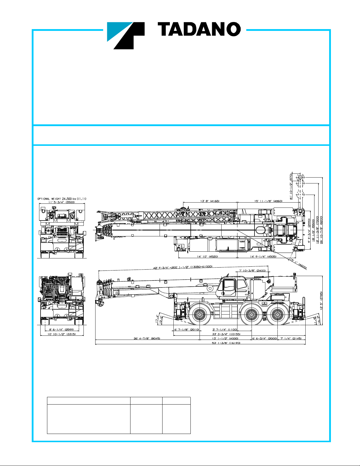
DIMENSIONS
GENERAL DIMENSIONS
(26.5 R25 Tires)
Feet Meters
Turning radius
6 wheel steer 32' 6" 9.9
2 wheel steer 48' 11" 14.9
Tail swing of counterweight 15' 1" 4.6
Note : Dimen sion is with boom angle at -1.5 degr ee.
Specifications are subject to change without notice.
Page 2

CRANE SPECIFICATIONS
BOOM WIRE ROPE - Non-rotating 3/4" (19mm) 7x35 class.
Six section boom, single cylinder telescoping with pinning system, Breaking Strength 79,400 lbs (36,000 kg)
42.8'~200.1' (13.1m~61.0m), of round box construction
with seven sheaves, 15-3/4" (0.400m) root diameter, at boom head. HOOK BLOCKS
Two easily removable wire rope guards, rope dead end provided 110 ton (100 metric ton) - 7 sheaves with swivel hook block
on both sides of boom head. Boom telescope sections are supported 7.9 ton (7.2 metric ton) - Weighted hook ball with swivel and safety latch.
by wear pads both vertically and horizontally.
Extension speed 157.3' in 430 seconds. COUNTERWEIGHT
Self-removable counterweight (40,100 + 24,500 = 64,600 lbs)
BOOM ELEVATION - By a double acting hydraulic cylinder with
holding valve. Elevation -1.5
or foot operation. Boom angle indicator.
Automatic speed reduction and soft stop function. PUMPS - Two variable piston pumps for crane functions.
Boom raising speed 20o to 60o in 28 seconds. Tandem gear pump for steering, swing and optional equipment.
JIB - Two stage bi-fold lattice type with 0
Single sheave, 17-5/16" (0.440m) root diameter, at the head of both
jib sections. Stored alongside base boom section. Jib length is CONTROL VALVES - Multiple valves actuated by pilot pressure
33.8' (10.3m) or 59.1' (18.0m). Assistant cylinders for mounting with integral pressure relief valves.
and stowing, controlled at right side of superstructure.
Self stowing jib mounting pins. RESERVOIR - 202 gallon (763 lit.) capacity. External sight level gauge.
AUXILIARY LIFTING SHEAVE (SINGLE TOP) FILTRATION - BETA10=10 return filter, full flow with bypass
Single sheave, 17-5/16" (0.440m) root diameter. Mounted to main protection, located inside of hydraulic reservoir. Accessible for
boom head for single line work (stowable). easy replacement.
o
~ 81.5 o, combination controls for hand HYDRAULIC SYSTEM
o
, 20 o or 40 o offset (tilt type). engaged/ disengaged by rotary switch from operator's cab.
Powered by carrier engine. Pump disconnect for crane is
ANTI-TWO BLOCK - Pendant type over-winding cut out device OIL COOLER - Air cooled fan type.
with audio-visual (FAILURE lamp/BUZZER) warning system.
SWING CAB AND CONTROLS
Hydraulic axial piston motor through planetary swing speed
reducer. Continuous 360
table at 1.3min
-1
swing brake. A 360
o
full circle swing on ball bearing turn Both crane and drive operations can be performed from one cab
{rpm}. Equipped with manually locked/released mounted on rotating superstructure.
o
positive swing lock manually engaged in cab.
Twin swing system: Free swing or lock swing controlled by Left side, 1 man type, tilting cab, steel construction with sliding door
selector switch on front console. access and safety glass windows opening at side. Door window is
powered control. Windshield glass window and roof glass window
HOIST are shatter-resistant. Tilt-telescoping steering wheel. Adjustable
control lever stands for swing, boom elevating, boom telescoping,
MAIN HOIST - Variable speed type with grooved drum driven by auxiliary hoist and main hoist. Control lever stands can change
hydraulic axial piston motor through speed reducer. Power load neutral positions and tilt for easy access to cab. 3 way adjustable
lowering and raising. Equipped with automatic brake (neutral brake) operator's seat with high back, headrest and armrest. Engine
and counterbalance valve. Controlled independently of auxiliary hoist. throttle knob. Foot operated controls: boom elevating,
Equipped with cable follower and drum rotation indicator. boom telescoping, service brake and engine throttle.
Hot water cab heater and air conditioning.
DRUM - Grooved 15" (0.382m) root diameter x 29-1/4" (0.742m) wide.
Wire rope: 1050' of 3/4" diameter rope (320m of 19mm). Dash-mounted engine start/stop, monitor lamps, cigarette lighter,
Drum capacity: 1293' (394m) 7 layers. drive selector switch, parking brake switch, steering mode
Maximum single line pull: 1st layer 21,800 lbs (9,900kg). select switch, power window switch, pump engaged/disengaged
Maximum permissible line pull (wire strength): 15,900 lbs (7,200kg). switch, swing brake switch, telescoping/auxiliary hoist select
switch, outrigger controls, free swing / lock swing selector switch,
AUXILIARY HOIST - Variable speed type with grooved drum driven eco mode switch, high speed hoist (main/aux) switch and ashtray.
by hydraulic axial piston motor through speed reducer. Power load
lowering and raising. Equipped with automatic brake (neutral brake) Instruments - Torque converter oil temperature, engine water
and counterbalance valve. Controlled independently of main hoist. temperature, air pressure, fuel, speedometer, tachometer,
Equipped with cable follower and drum rotation indicator. hour meter and odometer / tripmeter. Hydraulic oil pressure is
monitored and displayed on the AML-C display panel.
DRUM - Grooved 15" (0.382m) root diameter x 29-1/4" (0.742m)
wide. Wire rope: 738' of 3/4" diameter rope (225m of 19mm).
Drum capacity: 1293' (394m) 7 layers.
Maximum single line pull: 1st layer 21,800 lbs (9,900kg).
Maximum permissible line pull (wire strength): 15,900 lbs (7,200kg).
2
Page 3

Tadano electronic LOAD MOMENT INDICATOR system Main hoist / auxiliarly hoist select
(AML-C) including:
Control lever lockout function auxiliary hoist
Boom position indicator
Outrigger state indicator TADANO AML-C monitors outrigger extended length and
Boom angle / boom length / jib offset angle / jib length / load automatically programs the corresponding "RATED LIFTING
Drum rotation indicator (audible and visible type) main and
radius / rated lifting capacities / actual loads read out CAPACITIES" table
Ratio of actual load moment to rated load moment
indication Operator's right hand console includes transmission gear
Automatic Speed Reduction and Slow Stop function selector and sight level bubble. Upper console includes
on boom elevation and swing working light switch, roof washer and wiper switch
Working condition register switch emergency outrigger set up key switch,
Load radius / boom angle / tip height / swing range jib equipped/removed select switch, eco mode switch,
preset function high speed hoist (main / aux) switch,
External warning lamp boom emergency telescoping switch (2nd and 3rd-4th-top)
Tare function and air conditioning control switch. Swing lock lever.
Fuel consumption monitor
NOTE: Each crane motion speed is based on unladen
conditions.
CARRIER SPECIFICATIONS
TYPE - Rear engine, left hand steering, driving axle 2-way SUSPENSION
selected type by manual switch, 6x2 1st axle drive, 6x4 1st and 1st axle - Rigid mounted to frame.
3rd axle drive. 2nd and 3rd axles - "Hydro-Pneumatic suspension cylinders" with
leveling adjustment and oscillation.
FRAME - High tensile steel, all welded mono-box construction.
BRAKE SYSTEMS - Service: Air over hydraulic disc brakes on
TRANSMISSION - Electronically controlled full automatic all 6 wheels. Parking/Emergency: Spring applied-air released
transmission. Torque converter driving full powershift with brake acting on input shaft of 1st and 3rd axles. Auxiliary: Electrodriving axle selector. 5 forward and 2 reverse speeds, constant pneumatic operated exhaust brake.
mesh.
2 speeds - high range - 2 wheel drive; 4 wheel drive TIRES - 26.5 R25
3 speeds - low range - 4 wheel drive
OUTRIGGERS - Four hydraulic, beam and jack outriggers.
TRAVEL SPEED - 9.3 mph (15 km/h) *with counterweight Vertical jack cylinders equipped with integral holding valve. Each
TRAVEL SPEED - 2.4 mph (4 km/h) *without counterweight outrigger beam and jack is controlled independently from cab.
Beams extend to 26'10-7/8" (8.2 m) center-line and retract to
AXLE within 10' 10-1/2" (3.315 m) overall width with floats.
1st axle - Full floating type, Outrigger jack floats are attached thus eliminating the need of manually
steering and driving axle with planetary reduction. attaching and detaching them. Controls and sight bubble located
2nd axle -Steering axle in superstructure cab. Four outrigger extension lengths are provided
3rd axle - Full floating type, with corresponding "RATED LIFTING CAPACITIES" for crane duty
steering and driving axle with planetary reduction. in confined areas.
Self-removable outrigger boxes for ease of transportation.
STEERING- Hydraulic power steering controlled by steering Min. Extension 9' 9-3/4" (2.99m) center to center
wheel. Four steering modes available: 2 wheel front, 4 wheel Mid. Extension 18' 1/2" (5.50m) center to center
rear, 6 wheel coordinated and 6 wheel crab. Mid. Extension 23' 11-3/8" (7.30m) center to center
Emergency steering device. Max. Extension 26' 10-7/8" (8.20m) center to center
Float size(Diameter) 1' 10-1/2" (0.57m)
ENGINE
Model Mitsubishi 6M60 Radiator Fin and tube core, thermostat controlled
Type Direct injection diesel Fan, in.(mm) Suction type, 6-blade, 23.6 (600) dia.
No. of cylinders 6 Starting 24 volt
Combustion 4 cycle, turbo charged and after cooled Charging 24 volt system, negative ground
BoreXStroke, in.(mm) 4.646 x 4.528 (118 x 115) Battery 2-120 amp. Hour
Displacement, cu. in (liters) 460 (7.54) Compressor, air, CFM(l /min) 29 CFM (830) at 2,600rpm
Air inlet heater 24 volt preheat Horsepower (kW) Gross 267 (200) at 2,600rpm
Air cleaner Dry type, replaceable element Torque, Max. ft-lb (Nm) 579 (785) at 1,400rpm
Oil filter Full flow with replaceable element Capacity, gal.(liters)
Fuel filter Full flow with replaceable element Cooling water 3.4 (13)
Fuel tank, gal.(liters) 79.2 (300), right side of carrier
Cooling Liquid pressurized, recirculating by-pass Fuel 79.2 (300)
Lubrication 3.4 - 4.0 (13 - 15)
3
Page 4
STANDARD EQUIPMEN
T
E
- Six section boom, single cylinder telescoping with pinning system - Mitsubishi 6M60 turbo charged after cooled engine
42.8'~200.1' (13.05 m~61.0 m) (267HP) with exhaust brake
- 33.8' or 59.1' (10.3 m or 18.0 m) bi-fold lattice jib (tilt type) - Electronic controlled automatic transmission driven
o
with 0
, 20o or 40o pinned offsets and self stowing pins. by torque converter
- Quick reeving type bi-fold jib - 6 X 4 X 6 drive/steer
- Auxiliary lifting sheave (single top) stowable - Automatic 2nd and 3rd axle oscillation lock out system
- Variable speed main hoist with grooved drum, cable follower - 26.5 R25 tires
and 1050' of 3/4" cable. - Disc brakes
- Variable speed auxiliary hoist with grooved drum, cable follower - Fenders
and 738' of 3/4" cable. - Air dryer
- Drum rotation indicator (audible, visible and thumper type) main - Water separator with filter(high filtration)
and auxiliary hoist - Engine over-run alarm
- Anti-Two block device (overwind cutout) and lower limit (3rd wrap) - Back-up alarm
- Boom angle indicator - Low oil pressure/high water temp. warning device (visual)
- Tadano electronic load moment indicator system (AML-C) - 2nd and 3rd steer centering light
- Outrigger extension length detector - Air cleaner dust indicator
- Tadano twin swing system and 360
- Tilting cab - Tire inflation kit
- Self centering finger control levers with pilot control - 24 volt electric system
- Control pedals for boom elevating and boom telescoping - 7.9 ton (7.2 metric ton) hook ball with swivel
- 3 way adjustable cloth seat with armrests, high back - 110 ton (100 metric ton) - 7 sheaves with swivel hook block
and seat belt and safety latch for 3/4" wire rope
- Tilt-telescoping steering wheel - Weighted hook storage compartment
- Tinted safety glass and sun visor - Hook block tie down (front bumper)
- Front windshield wiper and washer - Towing hooks-Front and rear
- Roof window wiper and washer - Lifting eyes
- Power window (cab door ) - Halogen head lamp
- Rear view mirrors (right and left side) - Telematics (machine data logging and monitoring system)
- Mirror for main and auxiliary hoists with HELLO-NET via internet
- Cigarette lighter and ashtray - Fuel consumption monitor
- Cab floor mat - Eco mode system
- Pump disconnect in operator's cab - Self-removable counterweight (40,100 + 24,500 = 64,600 lbs)
- Hydraulic oil cooler - Self- removable outrigger boxes
-
Air conditioner (hot water heater and cooler) - Emergency steering assist
- Positive control - Anemometer
- Work lights
- Independently controlled outriggers
- Four outrigger extension positions
o
positive swing lock - Tool storage compartment
- Aircraft warning light
OPTIONAL EQUIPMENT
- 33.8' or 59.1' (10.3 m or 18.0 m) bi-fold lattice jib (tilt type) - 50 ton (45 metric ton) - 3 sheaves with swivel hook block
o
with 5
- 40o hydraulic offset. and safety latch for 3/4" wire rope
* Replaces standard fly jib if purchased as optional. - Boom removal assist system
HOISTING PERFORMANC
LINE SPEEDS AND PULLS DRUM WIRE ROPE CAPACITIES
Layer
1st 253 77 354 108 21,800 9,900 147.0 44.8 147.0 44.8
2nd 276 84 384 117 19,900 9,010 159.4 48.6 306.4 93.4
3rd 299 91 413 126 18,200 8,270 172.2 52.5 478.7 145.9
4th 318 97 446 136 16,800 7,640 184.7 56.3 663.4 202.2
5th 341 104 476 145 15,600 7,090 197.2 60.1 860.6 262.3
6th 361 110 505 154 14,600 6,620 209.6 63.9 1070.2 326.2
3
7th
* Maximum permissible line pull may be affected by wire rope strength.
Wire rope strength (7x35 class) = 15,900lbs (7,200kg)
1
Line speeds based only on hook block, not loaded. Inch mm
2
Developed by machinery with each layer of wire rope, but not based 15 382
on rope strength or other limitation in machinery or equipment. 29-1/4 742
3
Seventh layer of wire rope are not recommended 26-5/8 677
for hoisting operations.
Low High Low Rope per layer Total wire rope
F.P.M. m/min F.P.M. m/min Lbs. kgf Feet Meters Feet Meters
384 117 535 163 13,700 6,210 222.1 67.7 1292.3 393.9
Main or auxiliary hoist - 15" (0.382m) drum
Line speeds
1
Line pulls - Available
2
Wire
rope
layer
DRUM DIMENSIONS
Root diameter
Length
Flange diameter
Main and auxiliary drum grooved lagging
3/4" (19mm) wire rope
1
2
3
4
5
6
7
4
Page 5
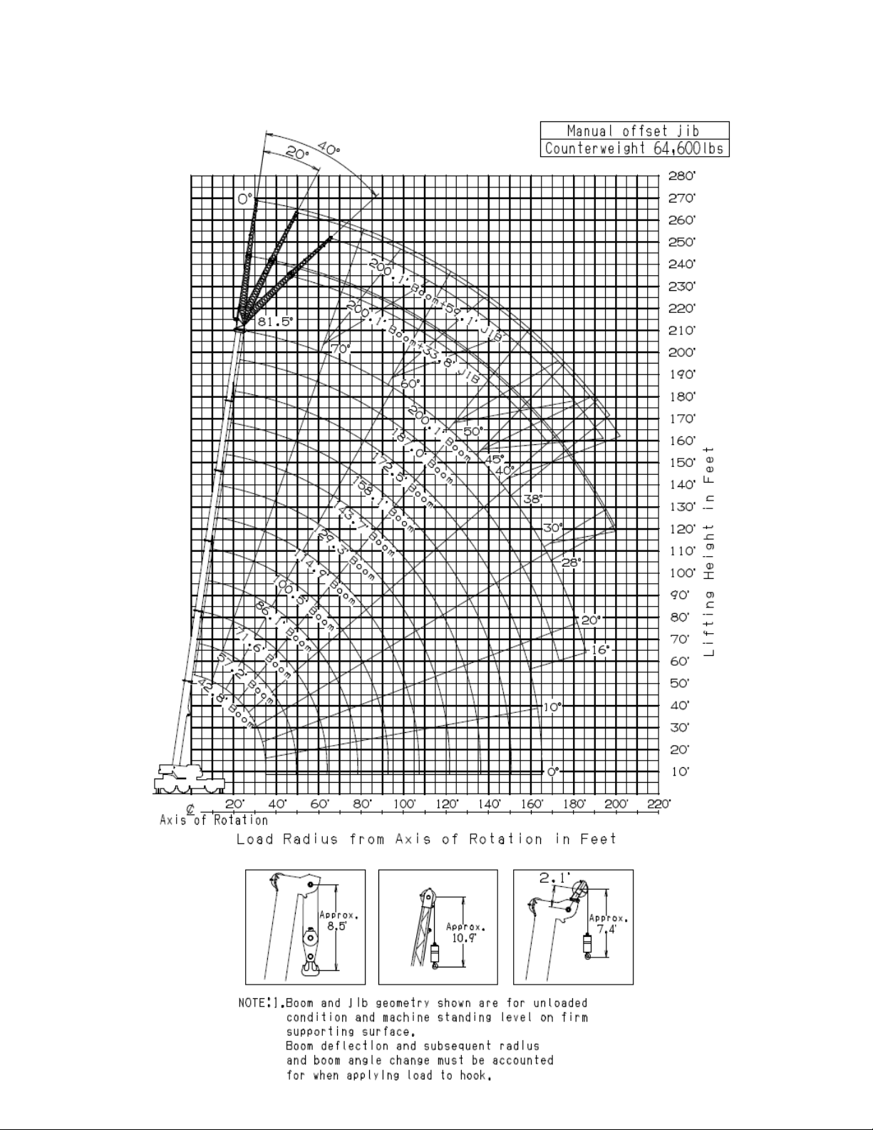
GR-1600XL WORKING RANGE CHART
5
Page 6

GR-1600XL WORKING RANGE CHART
6
Page 7

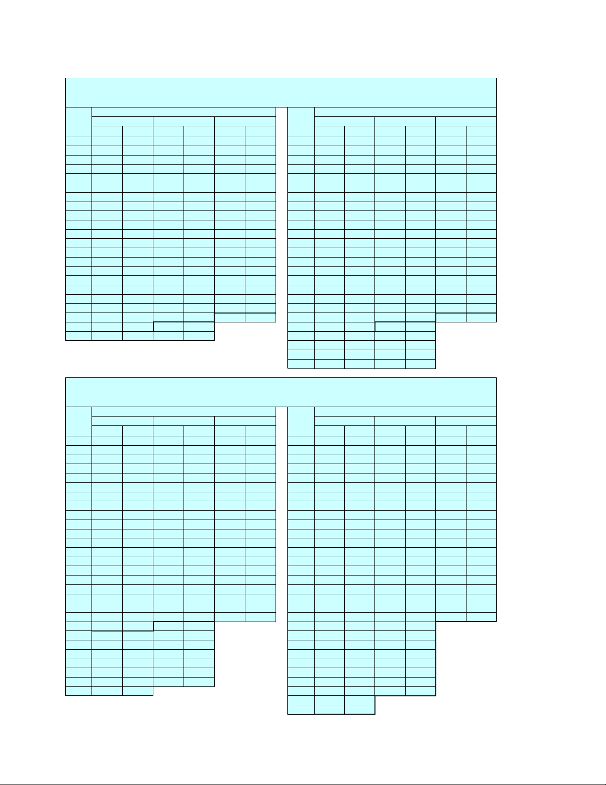
GR-1600XL RATED LIFTING CAPACITIES (IN POUNDS)
ON OUTRIGGERS FULLY EXTENDED 26' 10-7/8" (8.2m) SPREAD
COUNTERWEIGHT 64,550 lbs (29,300 kg)
A 42.8' 57.2' 71.6' 86.1' 100.5' 114.9' 129.3' 143.7' 158.1' 172.5' 187.0' 200.1'
B
8'
10'
12'
15'
20'
25'
30'
35'
45'
50'
60'
65'
75'
80'
90'
95'
105'
110'
120'
125'
130'
140'
145'
155'
160'
170'
175'
180'
185'
(13.1m) (17.4m) (21.8m) (26.2m) (30.6m) (35.0m) (39.4m) (43.8m) (48.2m) (52.6m) (57.0m) (61.0m)
** 320,000
241,800
218,000
187,100
148,300
121,500
101,000
48,700
200,000
200,000
200,000
182,800
148,800
122,400
102,500
85,100
64,200
174,200
174,200
174,200
174,200
145,500
122,800
102,700
85,300
62,400
54,700
45,400
145,500
145,500
138,700
120,800
102,100
84,700
64,200
56,200
44,300
41,000
32,600
111,800
106,300
106,300
97,700
86,200
63,300
55,600
46,100
41,400
33,500
30,200
23,600 26,000
** Over front and with additional lifting equipment
360
o
ROTATION
84,700
77,600
77,600
74,700
63,500
57,100
45,200
40,300
32,600
29,500
23,800
18,500
66,400
61,100
54,900
46,700
43,900
38,800
36,600
33,100
30,400
24,700
22,500
18,700
17,200
12,800
52,700
48,900
43,000
39,200
33,500
31,100
27,100
25,400
22,500
21,400
19,000
17,900
15,200
14,100
13,000
41,700
37,700
35,500
31,100
28,900
24,900
23,600
21,200
20,100
18,100
16,800
14,100 15,000
13,400
12,800
11,500
10,600
33,100
33,100
32,000
28,400
26,900
24,000
22,500
19,800
18,700
17,000
16,300
13,700
12,600
10,800
9,900
8,400
7,900
26,500
26,500
26,000
24,700
22,300
21,200
19,200
18,100
16,300
15,700
13,900
12,800
11,700
9,700
9,000
7,500
6,800 6,600
5,500
4,900
22,900
22,900
22,900
22,700
20,500
19,600
17,600
16,500
14,800
14,100
12,600
11,900
11,200
9,700
9,000
7,500
5,500
4,900
4,400
3,700
A :Boom length in f eet
B :Load radius in feet
7
Page 8

GR-1600XL RATED LIFTING CAPACITIES (IN POUNDS
)
g
(
)
0o, 20o or 40o pinned offsets
ON OUTRIGGERS FULLY EXTENDED 26' 10-7/8" (8.2m) SPREAD
200.1' (61.0m) Boom + 33.8' (10.3m) 187.0' (57.0m) Boom + 33.8' (10.3m)
C
81.5 43.3'
81 45.6' 12,100 59.4' 12,100 68.9' 11,200 81 41.0' 13,700 54.1' 13,700 63.0' 12,800
80 52.2' 12,100 64.6' 11,900 73.5' 10,800 80 45.9' 13,700 59.1' 13,700 67.3' 12,300
79 56.4' 12,100 69.9' 11,700 77.8' 10,600 79 50.9' 13,700 63.0' 13,200 71.2' 11,900
78 61.7' 12,100 73.8' 11,200 82.4' 10,400 78 55.5' 13,700 67.3' 12,800 75.1' 11,700
77 66.6' 12,100 78.1' 10,800 86.3' 9,900 77 60.4' 13,700 71.5' 12,300 79.1' 11,200
76 71.9' 12,100 83.0' 10,600 90.6' 9,700 76 65.0' 13,700 75.8' 12,100 83.0' 11,000
75 76.4' 11,700 87.3' 10,400 94.5' 9,500 75 69.2' 13,400 79.7' 11,700 86.9' 10,800
73 85.6' 11,000 95.8' 9,700 102.0' 9,000 73 77.4' 12,600 87.6' 11,000 94.2' 10,100
70 97.8' 9,900 108.0' 9,000 114.0' 8,400 70 89.2' 11,500 98.8' 10,100 105.0' 9,500
68 106.0' 9,500 115.0' 8,600 121.0' 7,900 68 96.5' 10,800 106.0' 9,700 112.0' 9,000
65 118.0' 8,800 127.0' 7,900 131.0' 7,500 65 107.0' 9,900 117.0' 9,000 121.0' 8,600
63 125.0' 8,200 134.0' 7,700 138.0' 7,300 63 115.0' 9,500 123.0' 8,600 128.0' 8,200
60 135.0' 7,500 143.0' 7,100 148.0' 6,800 60 125.0' 8,800 133.0' 8,200 137.0' 7,900
58 142.0' 7,100 150.0' 6,600 153.0' 6,400 58 132.0' 8,600 139.0' 7,900 142.0' 7,500
55 152.0' 6,600 159.0' 6,200 162.0' 6,000 55 141.0' 7,900 148.0' 7,500 151.0' 7,300
53 158.0' 6,200 165.0' 6,000 168.0' 5,700 53 146.0' 7,500 154.0' 7,300 156.0' 7,100
50 167.0' 5,500 173.0' 5,300 175.0' 5,100 50 155.0' 7,100 161.0' 6,600 163.0' 6,600
48 172.0' 5,100 178.0' 4,900 179.0' 4,900 48 160.0' 6,600 166.0' 6,400 168.0' 6,200
45 179.0' 4,600 185.0' 4,400 186.0' 4,400 45 167.0' 6,000 173.0' 5,700 174.0' 5,700
43 184.0' 4,200 190.0' 4,200 43 172.0' 5,700 177.0' 5,500
40 191.0' 3,700 195.0' 3,500 40 178.0' 5,300 183.0' 4,900
38 195.0' 3,300 199.0' 3,100 38 182.0' 4,600 186.0' 4,400
35 200.0' 2,600 204.0' 2,400 35 188.0' 4,000 191.0' 3,700
33 204.0' 2,400 207.0' 2,200 33 191.0' 3,700 194.0' 3,500
30 209.0' 2,000 211.0' 1,800 30 196.0' 3,300 198.0' 3,100
28 212.0' 1,800 28 199.0' 2,900 200.0' 2,900
o
0
offset 20o offset 40o offset
RWRWRW RWRWRW
12,100 56.8' 12,100 66.6' 11,500 81.5 38.7' 13,700 51.5' 13,700 61.0' 12,800
COUNTERWEIGHT 64,550 lbs (29,300 kg)
360
o
ROTATION
C
25 203.0' 2,600 203.0' 2,400
23 205.0' 2,400
20 208.0' 2,200
0o offset 20o offset 40o offset
ON OUTRIGGERS FULLY EXTENDED 26' 10-7/8" (8.2m) SPREAD
COUNTERWEIGHT 64,550 lbs (29,300 kg)
172.5' (52.6m) Boom + 33.8' (10.3m) 114.9' (35.0m) Boom + 33.8' (10.3m)
C
81.5 33.8'
81 35.8' 15,900 48.9' 15,900 58.7' 14,800 81 30.5' 23,100 38.4' 15,900
80 40.4' 15,900 53.5' 15,900 62.7' 14,300 80 33.1' 22,500 41.0' 15,700
79 45.0' 15,900 57.7' 15,700 66.3' 13,900 79 35.8' 22,000 43.3' 15,400
78 49.2' 15,900 61.7' 15,200 70.2' 13,400 78 39.0' 21,400 45.9' 15,200
77 53.8' 15,900 64.6' 14,600 73.8' 13,200 77 41.3' 20,900 48.6' 15,200
76 57.7' 15,900 69.2' 14,100 77.1' 12,800 76 43.6' 20,500 50.9' 15,000
75 62.3' 15,900 72.8' 13,700 80.7' 12,600 75 37.1' 31,100 46.3' 20,100 53.2' 14,800
73 69.9' 15,000 80.1' 13,000 87.6' 11,900 73 42.3' 29,100 51.2' 19,200 57.7' 14,300
70 81.4' 13,700 90.9' 11,900 97.1' 11,000 70 49.9' 26,900 58.7' 18,100 64.3' 13,900
68 88.3' 13,000 97.4' 11,500 103.0' 10,600 68 54.8' 25,600 63.3' 17,400 68.9' 13,700
65 98.8' 11,900 107.0' 10,800 113.0' 10,100 65 62.0' 23,800 70.2' 16,800 75.1' 13,400
63 105.0' 11,500 114.0' 10,400 118.0' 9,700 63 66.6' 22,900 74.8' 16,300 79.4' 13,200
60 115.0' 10,600 123.0' 9,700 127.0' 9,300 60 73.5' 21,800 81.4' 15,700 85.3' 13,000
58 121.0' 9,900 129.0' 9,300 133.0' 9,000 58 77.8' 21,200 85.3' 15,200 89.2' 12,800
55 130.0' 9,300 136.0' 8,800 140.0' 8,400 55 84.3' 20,100 91.2' 14,800 94.8' 12,800
53 135.0' 8,800 142.0' 8,400 145.0' 8,200 53 87.9' 19,200 95.1' 14,300 98.1' 12,600
50 143.0' 8,400 149.0' 7,900 152.0' 7,700 50 93.8' 18,300 100.0' 14,100 103.0' 12,600
48 148.0' 7,900 154.0' 7,500 156.0' 7,300 48 97.4' 17,600 104.0' 13,900 106.0' 12,600
45 155.0' 7,300 160.0' 6,800 161.0' 6,800 45 103.0' 17,000 109.0' 13,400 111.0' 12,300
43 159.0' 6,800 164.0' 6,600 43 106.0' 16,500 112.0' 13,400
40 165.0' 6,400 170.0' 6,000 40 111.0' 15,900 116.0' 13,200
38 169.0' 5,700 173.0' 5,500 38 115.0' 15,400 119.0' 13,000
35 174.0' 5,100 177.0' 4,900 35 119.0' 15,000 123.0' 13,000
33 177.0' 4,600 180.0' 4,400 33 121.0' 14,800 125.0' 12,800
30 182.0' 4,200 185.0' 4,000 30 125.0' 14,100 128.0' 12,800
28 185.0' 3,700 187.0' 3,500 28 127.0' 13,700 130.0' 12,800
25 188.0' 3,300 190.0' 3,300 25 131.0' 13,000 133.0' 12,600
23 191.0' 3,100 23 132.0' 12,600 R :Load radius in feet
20 193.0' 2,900 20 135.0' 12,100 W :Rated lifting capacity in pounds
o
0
offset 20o offset 40o offset
RWRWRW RWRWRW
15,900 46.9' 15,900 56.8' 15,000 81.5 29.2' 23,400 37.1' 16,100
360
o
ROTATION
C
0o offset 20o offset 40o offset
C :Loaded boom an
o
le
8
Page 9

GR-1600XL RATED LIFTING CAPACITIES (IN POUNDS
)
g
(
)
0o, 20o or 40o pinned offsets
ON OUTRIGGERS FULLY EXTENDED 26' 10-7/8" (8.2m) SPREAD
200.1' (61.0m) Boom + 59.1' (18.0m) 187.0' (57.0m) Boom + 59.1' (18.0m)
C
81.5 49.5'
81 52.8' 8,200 75.5' 8,200 92.5' 7,100 81 46.3' 8,800 69.2' 8,800 84.0' 7,300
80 58.1' 8,200 82.0' 8,200 97.1' 6,800 80 51.5' 8,800 74.5' 8,800 88.9' 7,300
79 64.3' 8,200 87.6' 8,200 102.0' 6,800 79 56.8' 8,800 79.4' 8,600 92.9' 7,100
78 70.5' 8,200 92.9' 7,900 107.0' 6,600 78 62.3' 8,800 84.3' 8,400 97.8' 7,100
77 75.5' 8,200 97.8' 7,700 112.0' 6,600 77 67.6' 8,800 88.9' 8,200 102.0' 6,800
76 81.7' 8,200 103.0' 7,500 116.0' 6,600 76 72.8' 8,800 93.8' 8,200 106.0' 6,800
75 87.3' 8,200 107.0' 7,300 120.0' 6,400 75 78.1' 8,800 98.4' 7,900 110.0' 6,800
73 97.4' 8,200 116.0' 6,800 129.0' 6,400 73 88.3' 8,800 107.0' 7,700 118.0' 6,600
70 111.0' 7,500 129.0' 6,400 140.0' 6,000 70 103.0' 8,800 120.0' 7,300 130.0' 6,400
68 120.0' 7,300 137.0' 6,200 148.0' 5,700 68 112.0' 8,400 128.0' 7,100 136.0' 6,200
65 133.0' 6,600 150.0' 5,700 158.0' 5,300 65 124.0' 7,700 139.0' 6,600 147.0' 6,200
63 142.0' 6,400 157.0' 5,500 166.0' 5,300 63 132.0' 7,500 147.0' 6,400 154.0' 6,000
60 154.0' 5,700 168.0' 5,300 175.0' 4,900 60 143.0' 6,800 157.0' 6,200 163.0' 5,700
58 161.0' 5,500 175.0' 4,900 181.0' 4,900 58 151.0' 6,600 164.0' 6,000 169.0' 5,500
55 172.0' 5,100 185.0' 4,600 190.0' 4,400 55 161.0' 6,200 173.0' 5,500 177.0' 5,300
53 178.0' 4,600 190.0' 4,200 194.0' 4,000 53 167.0' 5,700 179.0' 5,300 182.0' 5,100
50 187.0' 4,000 198.0' 3,500 201.0' 3,500 50 176.0' 5,300 187.0' 4,900 189.0' 4,600
48 193.0' 3,500 203.0' 3,300 205.0' 3,300 48 181.0' 4,900 192.0' 4,400 193.0' 4,400
45 201.0' 3,100 210.0' 2,900 211.0' 2,600 45 189.0' 4,400 198.0' 4,000 199.0' 3,700
43 206.0' 2,900 214.0' 2,400 43 194.0' 4,000 203.0' 3,700
40 213.0' 2,200 220.0' 2,000 40 201.0' 3,500 208.0' 3,100
38 218.0' 2,000 38 205.0' 3,100 212.0' 2,600
o
0
offset 20o offset 40o offset
RWRWRW RWRWRW
8,200 73.5' 8,200 89.2' 7,100 81.5 43.6' 8,800 66.3' 8,800 81.4' 7,300
COUNTERWEIGHT 64,550 lbs (29,300 kg)
360
o
ROTATION
C
35 211.0' 2,600 217.0' 2,200
33 215.0' 2,200 219.0' 2,000
30 220.0' 1,800
0o offset 20o offset 40o offset
ON OUTRIGGERS FULLY EXTENDED 26' 10-7/8" (8.2m) SPREAD
COUNTERWEIGHT 64,550 lbs (29,300 kg)
172.5' (52.6m) Boom + 59.1' (18.0m) 114.9' (35.0m) Boom + 59.1' (18.0m)
C
81.5 39.4'
81 42.0' 10,400 63.7' 9,700 78.1' 7,500 81 26.3' 14,100 45.0' 11,700 60.4' 8,200
80 46.9' 10,400 68.6' 9,500 83.0' 7,500 80 29.5' 14,100 48.2' 11,500 63.3' 7,900
79 52.2' 10,400 72.8' 9,300 86.9' 7,300 79 33.5' 14,100 51.5' 11,200 65.9' 7,900
78 56.8' 10,400 77.1' 9,000 90.9' 7,300 78 36.4' 14,100 54.5' 11,000 68.6' 7,900
77 61.7' 10,400 81.7' 8,800 94.8' 7,300 77 39.7' 14,100 57.4' 10,600 71.2' 7,700
76 65.9' 10,400 86.0' 8,600 98.8' 7,100 76 42.7' 14,100 60.7' 10,400 73.8' 7,700
75 71.2' 10,400 90.2' 8,600 102.0' 7,100 75 45.9' 14,100 63.3' 10,100 76.8' 7,700
73 81.0' 10,400 98.4' 8,200 110.0' 6,800 73 51.8' 14,100 69.6' 9,900 81.7' 7,500
70 94.2' 10,400 111.0' 7,900 120.0' 6,600 70 61.4' 13,900 74.5' 9,300 88.9' 7,300
68 102.0' 9,900 118.0' 7,700 127.0' 6,600 68 66.6' 13,200 83.3' 9,000 93.5' 7,100
65 114.0' 9,300 129.0' 7,300 136.0' 6,400 65 75.1' 12,300 91.2' 8,600 101.0' 7,100
63 121.0' 8,800 136.0' 7,100 143.0' 6,400 63 80.7' 11,700 96.5' 8,400 105.0' 7,100
60 132.0' 8,400 146.0' 6,800 152.0' 6,200 60 88.9' 11,000 104.0' 7,900 112.0' 6,800
58 139.0' 7,900 152.0' 6,800 158.0' 6,200 58 94.2' 10,600 108.0' 7,900 116.0' 6,800
55 149.0' 7,300 162.0' 6,600 166.0' 6,200 55 101.0' 10,100 115.0' 7,500 122.0' 6,800
53 155.0' 7,100 167.0' 6,400 171.0' 6,200 53 106.0' 9,700 120.0' 7,500 125.0' 6,600
50 163.0' 6,400 175.0' 5,700 177.0' 5,500 50 113.0' 9,300 126.0' 7,300 130.0' 6,600
48 169.0' 6,000 179.0' 5,500 181.0' 5,300 48 118.0' 9,000 130.0' 7,300 134.0' 6,600
45 176.0' 5,300 186.0' 4,900 187.0' 4,900 45 124.0' 8,600 135.0' 7,100 138.0' 6,600
43 181.0' 5,100 190.0' 4,600 43 128.0' 8,400 138.0' 7,100
40 188.0' 4,400 196.0' 4,000 40 134.0' 8,200 143.0' 6,800
38 192.0' 4,000 199.0' 3,500 38 137.0' 7,900 146.0' 6,800
35 198.0' 3,500 204.0' 3,100 35 142.0' 7,700 150.0' 6,800
33 202.0' 3,100 207.0' 2,600 33 145.0' 7,500 153.0' 6,800
30 208.0' 2,600 211.0' 2,200 30 150.0' 7,300 156.0' 6,800
28 211.0' 2,400 213.0' 2,000 28 153.0' 7,300 158.0' 6,800
25 215.0' 2,000 216.0' 1,800 25 156.0' 7,100 160.0' 6,800
23 218.0' 1,800 23 158.0' 7,100 R :Load radius in feet
o
0
offset 20o offset 40o offset
RWRWRW RWRWRW
10,400 61.4' 9,700 76.1' 7,500 81.5 24.3' 14,100 43.6' 11,900 59.1' 8,200
360
o
ROTATION
C
0o offset 20o offset 40o offset
C :Loaded boom an
20 161.0' 6,800 W :Rated lifting capacity in pounds
o
le
9
Page 10

GR-1600XL RATED LIFTING CAPACITIES (IN POUNDS
)
g
(
)
5o - 40o hydraulic offset - Optional
ON OUTRIGGERS FULLY EXTENDED 26' 10-7/8" (8.2m) SPREAD
200.1' (61.0m) Boom + 33.8' (10.3m) 187.0' (57.0m) Boom + 33.8' (10.3m)
C
81.5 48.2'
81 51.2' 12,100 61.0' 12,100 69.2' 11,000 81 44.9' 13,700 54.1' 13,700 63.3' 12,600
80 56.4' 12,100 65.3' 11,900 74.1' 10,800 80 49.9' 13,700 58.7' 13,400 67.6' 12,100
79 61.7' 12,100 69.6' 11,500 78.7' 10,400 79 54.8' 13,700 63.3' 13,000 71.9' 11,900
78 67.3' 12,100 74.1' 11,000 82.7' 10,100 78 59.7' 13,700 67.6' 12,600 75.5' 11,500
77 71.9' 11,900 80.1' 10,800 86.9' 9,900 77 64.3' 13,700 71.9' 12,300 79.7' 11,200
76 76.4' 11,500 83.0' 10,400 91.2' 9,700 76 68.2' 13,200 76.1' 11,900 83.3' 10,800
75 80.4' 11,000 87.6' 10,100 94.8' 9,300 75 72.5' 12,800 79.7' 11,500 87.3' 10,600
73 89.6' 10,600 96.1' 9,700 103.0' 8,800 73 80.7' 11,900 87.9' 10,800 94.8' 10,100
70 102.0' 9,500 108.0' 8,800 114.0' 8,400 70 92.5' 11,000 99.4' 10,100 105.0' 9,500
68 110.0' 9,000 116.0' 8,400 121.0' 7,900 68 100.0' 10,400 106.0' 9,500 112.0' 9,000
65 122.0' 8,400 127.0' 7,900 132.0' 7,500 65 111.0' 9,500 117.0' 8,800 122.0' 8,400
63 129.0' 7,900 134.0' 7,500 138.0' 7,300 63 118.0' 9,300 124.0' 8,600 128.0' 8,200
60 139.0' 7,300 144.0' 6,800 148.0' 6,600 60 128.0' 8,600 133.0' 8,200 137.0' 7,700
58 146.0' 6,800 151.0' 6,600 154.0' 6,400 58 135.0' 8,200 139.0' 7,700 143.0' 7,500
55 155.0' 6,200 159.0' 6,000 163.0' 6,000 55 144.0' 7,700 148.0' 7,300 151.0' 7,100
53 161.0' 6,000 165.0' 5,700 168.0' 5,500 53 150.0' 7,300 154.0' 7,100 156.0' 6,800
50 169.0' 5,300 173.0' 5,100 175.0' 4,900 50 158.0' 6,800 161.0' 6,400 164.0' 6,400
48 175.0' 4,900 178.0' 4,600 180.0' 4,600 48 163.0' 6,400 166.0' 6,200 168.0' 6,000
45 182.0' 4,400 185.0' 4,200 186.0' 4,200 45 170.0' 5,700 173.0' 5,500 174.0' 5,500
43 187.0' 4,000 190.0' 4,000 43 174.0' 5,300 177.0' 5,300
40 193.0' 3,500 195.0' 3,300 40 180.0' 4,900 183.0' 4,600
38 197.0' 3,100 199.0' 2,900 38 184.0' 4,400 186.0' 4,200
35 202.0' 2,400 204.0' 2,400 35 190.0' 3,700 191.0' 3,500
33 206.0' 2,200 207.0' 2,000 33 193.0' 3,500 194.0' 3,300
30 210.0' 1,800 30 198.0' 2,900 198.0' 2,900
o
5
offset 20o offset 40o offset
RWRWRW RWRWRW
12,100 57.1' 12,100 66.9' 11,200 81.5 42.3' 13,700 51.5' 13,700 61.4' 12,800
COUNTERWEIGHT 64,550 lbs (29,300 kg)
360
o
ROTATION
C
28 200.0' 2,600 201.0' 2,600
25 204.0' 2,400 203.0' 2,200
23 206.0' 2,200
20 208.0' 2,000
5o offset 20o offset 40o offset
ON OUTRIGGERS FULLY EXTENDED 26' 10-7/8" (8.2m) SPREAD
COUNTERWEIGHT 64,550 lbs (29,300 kg)
172.5' (52.6m) Boom + 33.8' (10.3m) 114.9' (35.0m) Boom + 33.8' (10.3m)
C
81.5 37.1'
81 39.4' 15,900 49.2' 15,900 59.1' 14,800 81 30.5' 23,100 38.4' 15,900
80 44.0' 15,900 53.5' 15,900 63.0' 14,300 80 33.1' 22,500 41.0' 15,700
79 48.6' 15,900 57.7' 15,400 66.6' 13,900 79 35.8' 22,000 43.3' 15,400
78 52.8' 15,900 61.7' 15,000 70.2' 13,400 78 39.0' 21,400 45.9' 15,200
77 57.4' 15,900 65.3' 14,600 73.8' 13,000 77 41.3' 20,900 48.6' 15,200
76 61.7' 15,900 69.2' 14,100 77.4' 12,800 76 43.6' 20,500 50.9' 15,000
75 64.3' 15,200 73.2' 13,700 80.7' 12,300 75 38.7' 28,200 46.3' 20,100 53.1' 14,800
73 72.2' 14,300 80.1' 12,800 87.6' 11,900 73 44.0' 26,900 51.2' 19,200 57.7' 14,300
70 84.3' 13,000 90.6' 11,900 97.1' 11,000 70 51.2' 24,900 58.7' 18,100 64.6' 13,900
68 91.5' 12,300 97.8' 11,500 104.0' 10,600 68 56.4' 23,800 63.3' 17,400 68.9' 13,700
65 102.0' 11,500 107.0' 10,600 113.0' 9,900 65 63.3' 22,300 70.2' 16,800 75.1' 13,400
63 109.0' 11,000 114.0' 10,100 118.0' 9,700 63 67.9' 21,200 74.8' 16,300 79.4' 13,200
60 118.0' 10,100 123.0' 9,700 127.0' 9,300 60 74.8' 19,800 81.4' 15,700 85.3' 13,000
58 124.0' 9,700 129.0' 9,300 133.0' 8,800 58 79.1' 19,200 85.3' 15,200 89.2' 12,800
55 133.0' 9,000 137.0' 8,600 140.0' 8,400 55 85.3' 18,100 91.5' 14,800 94.8' 12,600
53 138.0' 8,600 142.0' 8,400 145.0' 7,900 53 89.2' 17,400 95.1' 14,300 98.1' 12,600
50 146.0' 8,200 149.0' 7,700 151.0' 7,500 50 95.1' 16,800 101.0' 14,100 103.0' 12,600
48 151.0' 7,700 154.0' 7,300 156.0' 7,100 48 99.0' 16,300 104.0' 13,900 106.0' 12,300
45 157.0' 7,100 160.0' 6,600 162.0' 6,600 45 104.0' 15,700 109.0' 13,400 111.0' 12,300
43 162.0' 6,600 164.0' 6,400 43 107.0' 15,400 112.0' 13,400
40 168.0' 6,000 170.0' 5,700 40 112.0' 15,000 116.0' 13,200
38 171.0' 5,500 173.0' 5,300 38 115.0' 14,600 119.0' 13,000
35 176.0' 4,900 178.0' 4,600 35 120.0' 14,300 123.0' 13,000
33 179.0' 4,400 181.0' 4,200 33 122.0' 14,100 125.0' 12,800
30 183.0' 3,700 185.0' 3,700 30 126.0' 13,900 129.0' 12,800
28 186.0' 3,500 187.0' 3,300 28 128.0' 13,200 131.0' 12,800
25 190.0' 3,100 190.0' 3,100 25 131.0' 12,600 133.0' 12,300
23 192.0' 2,900 23 133.0' 12,300 R :Load radius in feet
20 194.0' 2,600 20 135.0' 11,900 W :Rated lifting capacity in pounds
o
5
offset 20o offset 40o offset
RWRWRW RWRWRW
15,900 46.9' 15,900 57.1' 15,000 81.5 29.2' 23,400 37.1' 16,100
360
o
ROTATION
C
5o offset 20o offset 40o offset
C :Loaded boom an
o
le
10
Page 11
GR-1600XL RATED LIFTING CAPACITIES (IN POUNDS
)
g
(
)
5o - 40o hydraulic offset - Optional
ON OUTRIGGERS FULLY EXTENDED 26' 10-7/8" (8.2m) SPREAD
200.1' (61.0m) Boom + 59.1' (18.0m) 187.0' (57.0m) Boom + 59.1' (18.0m)
C
81.5 56.1'
81 59.1' 8,200 74.5' 8,200 91.9' 7,100 81 49.2' 8,800 68.2' 8,800 83.7' 7,300
80 65.3' 8,200 81.0' 8,200 97.1' 6,800 80 56.4' 8,800 73.8' 8,800 88.6' 7,100
79 70.9' 8,200 86.3' 8,200 102.0' 6,800 79 61.7' 8,800 78.1' 8,600 92.8' 7,100
78 76.8' 8,200 91.5' 7,900 107.0' 6,600 78 66.6' 8,800 83.3' 8,400 97.4' 7,100
77 82.0' 8,200 96.1' 7,700 112.0' 6,600 77 71.9' 8,800 87.6' 8,200 102.0' 6,800
76 87.9' 8,200 101.0' 7,500 116.0' 6,600 76 77.1' 8,800 92.5' 7,900 106.0' 6,800
75 93.5' 8,200 106.0' 7,300 119.0' 6,400 75 82.0' 8,800 97.1' 7,900 110.0' 6,600
73 103.0' 7,700 115.0' 6,800 129.0' 6,200 73 92.2' 8,800 106.0' 7,700 118.0' 6,600
70 117.0' 7,100 128.0' 6,400 140.0' 5,700 70 106.0' 8,200 119.0' 7,300 129.0' 6,400
68 126.0' 6,800 135.0' 6,000 147.0' 5,500 68 114.0' 7,700 127.0' 7,100 137.0' 6,200
65 138.0' 6,200 149.0' 5,700 158.0' 5,300 65 126.0' 7,300 138.0' 6,600 147.0' 6,200
63 147.0' 6,000 156.0' 5,500 165.0' 5,100 63 135.0' 7,100 146.0' 6,400 154.0' 6,000
60 159.0' 5,500 167.0' 5,100 175.0' 4,900 60 146.0' 6,600 156.0' 6,000 163.0' 5,700
58 166.0' 5,100 174.0' 4,900 181.0' 4,600 58 153.0' 6,400 163.0' 5,700 169.0' 5,500
55 176.0' 4,600 183.0' 4,400 189.0' 4,200 55 163.0' 6,000 172.0' 5,500 177.0' 5,300
53 182.0' 4,200 189.0' 4,000 194.0' 3,700 53 169.0' 5,500 177.0' 5,100 182.0' 4,900
50 191.0' 3,700 197.0' 3,500 200.0' 3,300 50 177.0' 4,900 186.0' 4,600 189.0' 4,400
48 197.0' 3,300 201.0' 3,100 205.0' 3,100 48 183.0' 4,600 190.0' 4,200 193.0' 4,200
45 205.0' 2,900 209.0' 2,600 211.0' 2,400 45 191.0' 4,000 198.0' 3,700 199.0' 3,700
43 210.0' 2,600 213.0' 2,400 43 196.0' 3,700 202.0' 3,500
40 216.0' 2,000 219.0' 1,800 40 202.0' 3,300 207.0' 2,900
o
5
offset 20o offset 40o offset
RWRWRW RWRWRW
8,200 72.2' 8,200 88.9' 7,100 81.5 47.9' 8,800 65.6' 8,800 81.0' 7,300
COUNTERWEIGHT 64,550 lbs (29,300 kg)
360
o
ROTATION
C
38 207.0' 2,900 211.0' 2,600
35 212.0' 2,200 216.0' 2,000
33 216.0' 2,000 219.0' 1,800
5o offset 20o offset 40o offset
ON OUTRIGGERS FULLY EXTENDED 26' 10-7/8" (8.2m) SPREAD
COUNTERWEIGHT 64,550 lbs (29,300 kg)
172.5' (52.6m) Boom + 59.1' (18.0m) 114.9' (35.0m) Boom + 59.1' (18.0m)
C
81.5 44.9'
81 47.6' 10,400 64.3' 9,700 78.4' 7,500 81 31.5' 14,100 45.9' 11,700 60.4' 8,200
80 52.8' 10,400 69.2' 9,500 82.7' 7,500 80 35.1' 14,100 49.2' 11,500 63.3' 7,900
79 57.7' 10,400 73.5' 9,300 86.6' 7,300 79 38.4' 14,100 52.5' 11,200 65.9' 7,900
78 63.0' 10,400 78.1' 9,000 90.9' 7,300 78 41.7' 14,100 55.4' 11,000 68.6' 7,900
77 67.3' 10,400 82.0' 8,800 94.8' 7,300 77 44.6' 14,100 58.4' 10,600 71.2' 7,700
76 72.2' 10,400 86.3' 8,600 98.1' 7,100 76 47.9' 14,100 61.0' 10,400 73.8' 7,700
75 76.8' 10,400 90.9' 8,600 102.0' 7,100 75 51.2' 14,100 64.0' 10,100 76.4' 7,700
73 86.6' 10,100 98.8' 8,200 110.0' 6,800 73 57.1' 13,200 70.2' 9,900 81.7' 7,500
70 98.0' 9,500 111.0' 7,700 120.0' 6,600 70 65.9' 12,300 74.8' 9,300 88.9' 7,300
68 114.0' 9,300 118.0' 7,500 127.0' 6,600 68 71.5' 11,700 83.7' 9,000 93.5' 7,100
65 119.0' 8,800 129.0' 7,300 136.0' 6,400 65 80.1' 11,000 91.5' 8,600 100.0' 7,100
63 126.0' 8,400 135.0' 7,100 143.0' 6,400 63 85.3' 10,600 96.5' 8,400 105.0' 7,100
60 136.0' 7,900 146.0' 6,800 152.0' 6,200 60 93.2' 10,100 104.0' 7,900 112.0' 6,800
58 143.0' 7,500 153.0' 6,800 157.0' 6,200 58 98.1' 9,700 109.0' 7,900 116.0' 6,800
55 153.0' 7,100 162.0' 6,600 165.0' 6,200 55 105.0' 9,300 115.0' 7,500 122.0' 6,600
53 159.0' 6,600 167.0' 6,200 170.0' 6,000 53 110.0' 9,000 120.0' 7,500 125.0' 6,600
50 167.0' 6,000 174.0' 5,500 176.0' 5,300 50 117.0' 8,600 126.0' 7,300 130.0' 6,600
48 173.0' 5,500 179.0' 5,300 180.0' 5,100 48 121.0' 8,400 130.0' 7,300 134.0' 6,600
45 180.0' 5,100 186.0' 4,900 186.0' 4,600 45 127.0' 8,200 135.0' 7,100 138.0' 6,600
43 185.0' 4,900 190.0' 4,400 43 131.0' 7,900 138.0' 7,100
40 191.0' 4,200 195.0' 3,700 40 136.0' 7,700 143.0' 6,800
38 196.0' 3,700 199.0' 3,300 38 143.0' 7,500 146.0' 6,800
35 201.0' 3,100 204.0' 2,900 35 145.0' 7,300 150.0' 6,800
33 205.0' 2,900 207.0' 2,600 33 148.0' 7,300 153.0' 6,800
30 210.0' 2,400 211.0' 2,200 30 152.0' 7,100 156.0' 6,800
28 213.0' 2,200 213.0' 2,000 28 155.0' 7,100 158.0' 6,800
25 217.0' 1,800 25 158.0' 6,800 160.0' 6,800
o
5
offset 20o offset 40o offset
RWRWRW RWRWRW
10,400 61.7' 9,700 76.1' 7,500 81.5 30.2' 14,100 44.6' 11,900 58.7' 8,200
360
o
ROTATION
C
5o offset 20o offset 40o offset
C :Loaded boom an
23 160.0' 6,800 R :Load radius in feet
20 163.0' 6,800 W :Rated lifting capacity in pounds
o
le
11
Page 12

WARNING AND OPERATING INSTRUCTIONS
FOR LIFTING CAPACITIES
GENERAL
1. RATED LIFTING CAPACITIES apply only to the machine as 11. Load per line should not exceed 15,900 lbs. (7,200kg) for
originally manufactured and normally equipped by TADANO main hoist and auxiliary hoist.
LTD. Modifications to the machine or use of optional 12. Check the actual number of parts of line with LOAD MOMENT
equipment other than that specified can result in a reduction INDICATOR (AML-C) before operation. Maximum lifting
of capacity. capacity is restricted by the number of parts of line of LOAD
2. Hydraulic cranes can be hazardous if improperly MOMENT INDICATOR (AML-C). Limited capacity is as
operated or maintained. Operation and maintenance of this determined from the formula, Single line pull for main hoist
machine must be in compliance with information in the 15,900 lbs. (7,200kg) x number of parts of line.
Operation and Maintenance Manual supplied with 13. The boom angle before loading should be greater to account
the crane. If this manual is missing, order a replacement for deflection. For rated lifting capacities, the loaded boom
through the distributor. angle and the load radius is for reference only.
3. The operator and other personnel associated with this 14. Do not operate extension or retraction of the boom with loads.
machine shall fully acquaint themselves with the latest Extension or retraction of the boom with loads may be
applicable ASME B30.5 safety standards for cranes as attempted within the limits of the RATED LIFTING CAPACITIES.
mentioned in OSHA CFR29 part 1926. The ability to telescope loads is limited by hydraulic pressure,
SET UP 15. For lifting capacity of single top, deduct the weight of the load
1. Rated lifting capacities on the load chart are the maximum handling equipment from the rated lifting capacity of the boom.
allowable crane capacities. They are based on the machine For the lifting capacity of single top, the net capacity shall not exceed
standing level on firm supporting surface under ideal job 15,900lbs (7,200kg) including main boom hook mass attached
conditions. Depending on the nature of the supporting to the boom.
surface, it may be necessary to have structural supports 16. When the base jib or top jib or both jibs are removed, set the jib state
under the outrigger floats or tires to spread the loads to a switch to the REMOVED position.
larger surface. 17. When erecting and stowing jib, be sure to retain it by hand or by
2. For outrigger operation, outriggers shall be properly extended other means to prevent its free movement.
with tires free of supporting surface before operating crane. 18. Use "ANTI-TWO BLOCK" disable switch when erecting and
OPERATION pushed, the hoist does not stop, even when overwind condition
1. Rated lifting capacities have been tested to and meet occurs.
minimum requirements of SAE J1063-Cantilevered Boom 19. When lifting a load by using jib (aux. hoist) and boom (main hoist)
Crane Structures Method of Test. simultaneously, do the following:
2. Rated lifting capacities do not exceed 85 % of the tipping
load on outriggers fully extended as determined by SAE operation.
J765-Crane Stability Test Code.
Rated lifting capacities for partially extended outriggers are within rated lifting capacity for jib.
determined from the formula, Rated Lifting Capacities
=(Tipping Load - 0.1 x Tip Reaction)/1.25.
3. Rated lifting capacities above bold lines in the chart are DEFINITIONS
based on crane strength and those below, on its stability. 1. Load Radius: Horizontal distance from a projection of the axis
They are based on actual load radius increased by boom of rotation to supporting surface before loading to the center of
deflection. the vertical hoist line or tackle with load applied.
4. The weight of handling device such as hook blocks, slings, 2. Loaded Boom Angle: The angle between the boom base
etc., must be considered as part of the load and must be section and the horizontal, after lifting the rated lifting capacity
deducted from the lifting capacities. at the load radius.
5. Rated lifting capacities are based on freely suspended loads 3. Working Area: Area measured in a circular arc about the
and make no allowance for such factors as the effect of wind, centerline of rotation.
sudden stopping of loads, supporting surface conditions, 4. Freely Suspended Load: Load hanging free with no direct
inflation of tires, operating speeds, side loads, etc. Side pull external force applied except by the hoist line.
on the boom or jib is extremely dangerous. 5. Side Load: Horizontal side force applied to the lifted load either
Such action can damage the boom, jib or swing mechanism, on the ground or in the air.
and lead to overturning the crane.
6. Rated lifting capacities do not account for wind on lifted load
or boom. We recommend against working under the condition
that the load is out of control due to a strong wind.During
boom lift, consider that the rated lifting capacity is reduced by
50% when the wind speed is 20mph(9m/s) to 27mph(12m/s);
reduced by 70% when the wind speed is 27mph(12m/s) to
31mph(14m/s).If the wind speed is 31mph(14m/s) or over,
stop operation. During jib lift, stop operation if the wind speed
is 20mph(9m/s).
7. Rated lifting capacities at load radius shall not be exceeded.
Do not tip the crane to determine allowable loads.
8. Do not operate at boom lengths, radii, or boom angle, where
no capacities are shown. Crane may overturn without any
load on the hook.
9. When boom length is between values listed, refer to the
rated lifting capacities of the next longer and next shorter
booms for the same radius. The lesser of the two rated lifting
capacities shall be used.
10. When making lifts at a load radius not shown, use the next
longer radius to determine allowable capacity.
boom angle, boom length, crane maintenance, etc.
stowing jib and when stowing hook block. While the switch is
Enter the operation status as jib operation, not as boom
Before starting operation, make sure that mass of load is
12
Page 13
GR-1600XL RATED LIFTING CAPACITIES (IN POUNDS)
g
(
)
(
)
)
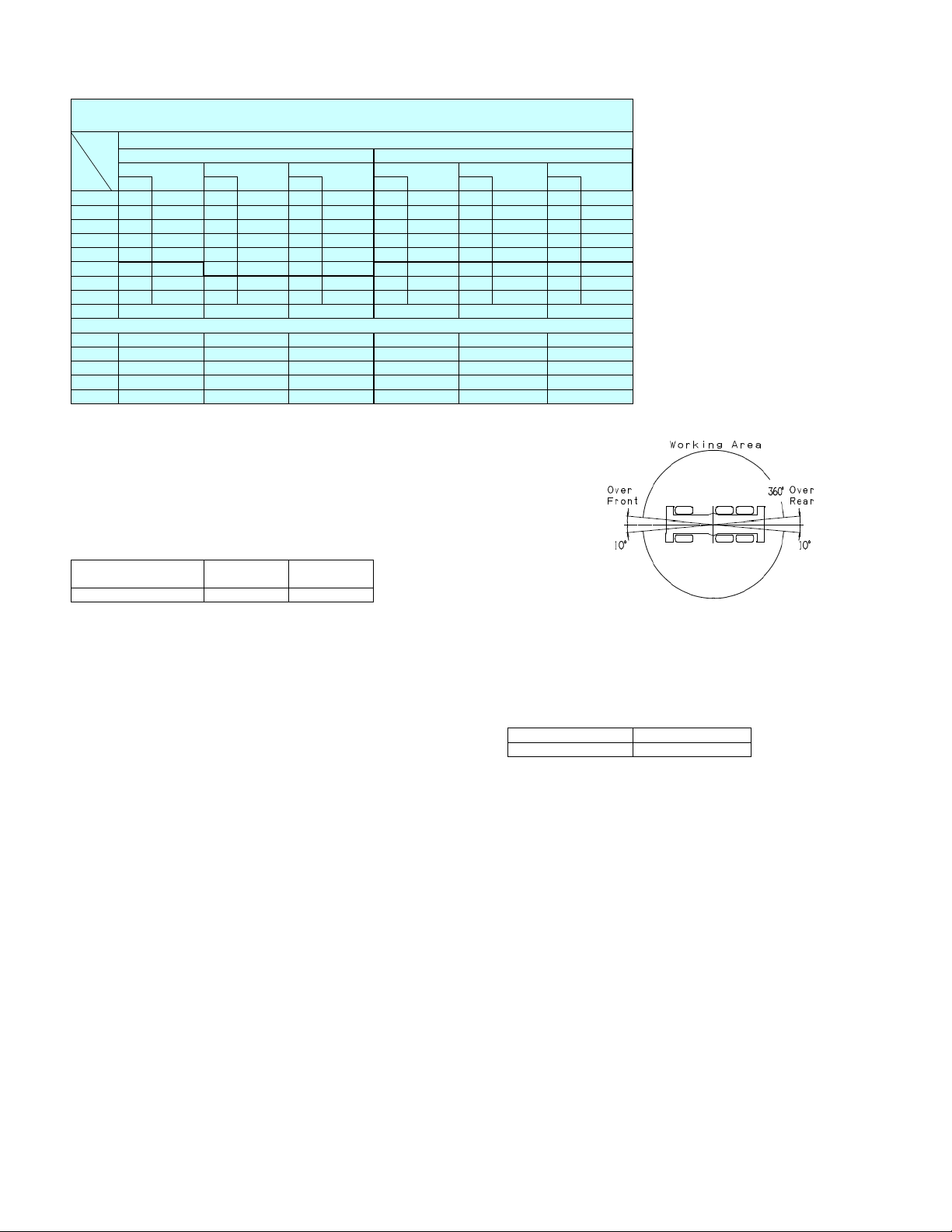
ON RUBBER
Without counterweight
A
Over Front and Rear
42.8' 57.2' 71.6' 42.8' 57.2' 71.6'
BC
(13.1m)
C
(17.4m)
C
8' 73 22,000 78 22,000 81 22,000 73 22,000 78 81 22,000
10' 70 22,000 76 22,000 79 22,000 70 22,000 76 79 22,000
67 22,000 73 22,000 77 22,000 67 20,500 73 77 22,000
12'
15' 63 22,000 70 22,000 75 22,000 63 13,700 70 75 19,400
20'
54 14,800 65 18,100 71 19,600 54 6,200 65 71 12,100
25' 45 9,000 59 12,300 66 14,100 59 66 7,100
30' 33 3,500 53 7,700 62 9,700 62 3,300
35' 45 4,000 57 6,000
D
0 455754 5962
Telescoping conditions (%)
2nd boom
3rd boom
4th boom 000000
5th boom 000000
Top boom
00000 0
00000 0
0 45 90 0 45 90
A :Boom length in feet
B :Load radius in feet
C :Loaded boom an
D :Minimum boom angle
o
le
o
for indicated length (no load
Stationary
(21.8m)
C
(13.1m)
360
C
o
Rotation
(17.4m)
22,000
22,000
22,000
17,400
9,900
4,900
C
(21.8m)
NOTE: The lifting capacity data stored in the LOAD MOMENT INDICATOR (AML-C) is based
on the standard number of parts of line listed in the chart.
Standard number of parts of line for rubber operation should be according to the
following table.
Boom length in feet 42.8' 42.8' to 71.6'
(meters) (13.1m) (13.1m to 21.8m)
Number of parts of line 4 4
WARNING AND OPERATING INSTRUCTIONS
FOR ON RUBBER LIFTING CAPACITIES
1. Rated lifting capacities on rubber are in pounds and do not exceed 6. Tires shall be inflated to correct air pressure.
75 % of tipping loads as determined by SAE J765-Crane Stability Tires Air Pressure
Test Code. 29.5R25 94 psi (650kPa)
2. On rubber lifting is only permitted without counterweight and 7. Over front and rear operation shall be performed within 10 degrees
stationary. Creep operation is prohibited. in front/rear of chassis.
3. Rated lifting capacities shown in the chart are based on condition 8. On rubber lifting with "jib" is not permitted. Maximum permissible
that crane is set on firm level surfaces with suspension fully-retracted boom length is 71.6'. (21.8m).
Those above bold lines are based on tire capacity and 9. When making lift on rubber stationary, set parking brake.
those below, on crane stability. They are based on actual load
radius increased by tire deformation and boom deflection.
4. If the suspension cylinders contain air, the axle will not
be locked completely and rated lifting capacities may not be
obtainable. Bleed the cylinders according to the operation safety
and maintenance manual.
5. Rated lifting capacities are based on proper tire inflation, capacity
and condition. Damaged tires are hazardous to safe operation of
crane.
13
Page 14

GR-1600XL Axle weight distribution chart
o
0
, 20o or 40o pinned offsets fly jib
Base machine
incl. standard fly jib and auxiliary winch
7.9 ton (7.2 metric ton) hook ball -661 -928 134 134 -300 -421 61 61
Auxiliary winch & wire rope -2,650 1,080 -1,865 -1,865 -1,202 490 -846 -846
Remove: Front and rear outrigger boxes and beams -19,758 -7,635 -6,063 -6,063 -8,962 -3,463 -2,750 -2,750
2 section manual offset fly jib -3,197 -5,073 939 939 -1,450 -2,301 426 426
Boom -34,445 -43,094 4,325 4,325 -15,624 -19,547 1,962 1,962
Counterweight 24,500 lbs (11,100 kg) 24,515 -7,388 15,953 15,953 11,120 -3,351 7,236 7,236
Add: Counterweight 40,100 lbs (18,200 kg) 40,036 -12,066 26,050 26,050 18,160 -5,473 11,816 11,816
110 ton (100 metric ton) hook block 2,381 3,904 -763 -763 1,080 1,771 -346 -346
o
- 40o hydraulic offset - Optional
5
Base machine
incl. standard fly jib and auxiliary winch
Remove: 7.9 ton (7.2 metric ton) hook ball -661 -928 134 134 -300 -421 61 61
Auxiliary winch & wire rope -2,650 1,080 -1,865 -1,865 -1,202 490 -846 -846
Front and rear outrigger boxes and beams -19,758 -7,635 -6,063 -6,063 -8,962 -3,463 -2,750 -2,750
2 section hydraulic offset fly jib -3,417 -5,585 1,085 1,085 -1,550 -2,533 492 492
Boom -34,996 -44,183 4,592 4,592 -15,874 -20,041 2,083 2,083
Add: Counterweight 24,500 lbs (11,100 kg) 24,515 -7,388 15,953 15,953 11,120 -3,351 7,236 7,236
Counterweight 40,100 lbs (18,200 kg) 40,036 -12,066 26,050 26,050 18,160 -5,473 11,816 11,816
110 ton (100 metric ton) hook block 2,381 3,904 -763 -763 1,080 1,771 -346 -346
Total Axle 1 Axle 2 Axle 3 Total Axle 1 Axle 2 Axle 3
133,259 78,825 26,693
Total Axle 1 Axle 2 Axle 3 Total Axle 1 Axle 2 Axle 3
Pounds Kilograms
27,743
Pounds Kilograms
60,445 35,754 12,108 12,584
36,451134,028 80,361 26,310 27,359 60,794
11,934 12,410
14
Page 15

MEMO
15
Page 16

MEMO
16
TADANO AMERICA Corporation
4242 West Greens Road
Houston, TX 77066
Phone: 281-869-0030
Fax: 281-869-0040
www.tadanoamerica.com
E-mail: sales@tadano-cranes.com
Form No. TAC-GR-1600XL-2-01132014
 Loading...