

Page 1

ROUGH TERRAIN CRANE
SPEC. SHEET NO. GR-1450E-2-00101/EX-03
GR-1450EX
Left - hand steering
GENERAL DATA
CRANE CAPACITY
BOOM
DIMENSION
Overall length approx. 16,190 mm
Overall width approx. 3,315 mm
Overall height approx. 3,785 mm
MASS
Gross vehicle mass approx. 90,805 kg
PERFORMANCE
Max. travelling speed
(with counterweight) computed 15 km/h
Gradeability(tan )
(with 18.2t counterweight) computed 52 % (at stall)
*Machine should be operated within the limit of engine crankcase
design (17˚ : MITSUBISHI 6M60-TL).
CRANE SPECIFICATIONS
MODEL
GR-1450EX
CAPACITY
145,000 kg at 2.5 m
145,000 kg at 2.5 m
6-section, 13.1 m - 61.0m
-1st axle approx. 28,701 kg
-2nd axle approx. 30,814 kg
-3rd axle approx. 31,290 kg
*30 %
ELEVATION
By a double-acting hydraulic cylinder, fitted with holding valve.
Automatic speed reduction and slow stop function.
Boom angle .............................. -1.5˚ to 81.5˚
Boom raising speed ................. 20˚ to 60˚ in 28 s
BOOM
Six sections extended by single telescoping cylinder,
13.1m~61.0m, of round box construction with 7 sheaves, 0.400m
root diameter, at boom head.
Hydraulic cylinders fitted with holding valves.
Fully retracted length ............... 13.1 m
Fully extended length ............... 61.0 m
Extension speed ....................... 47.9 m in 450 s
JIB
Two staged slewing around boom extension. Triple offset
(0˚/20˚/40˚) type. Stows alongside base boom section.
Assistant cylinders for mounting and stowing.
Single sheave at jib head.
Length ..................................... 10.3 m and 18.0 m
SINGLE TOP (AUXILIARY BOOM SHEAVE)
Single sheave, 0.440m root diameter. Mounted to main boom
head for single line work.
HOIST-Main winch
Variable speed type with grooved drum driven by hydraulic axial
piston motor through winch speed reducer. Power load lowering
and hoisting. Equipped with automatic brake (Neutral brake) and
counterbalance valve. Controlled independently of auxiliary
winch.
Single line pull ............................. 70.6 kN {7,200 kgf}
Single line speed(High) ............... 136 m/min (at the 4th layer)
Single line speed(Low) ................ 97 m/min (at the 4th layer)
Wire rope ..................................... No-spin type
Diameter x length ........................ 19 mm x 320 m
HOOK BLOCK(Optional) - 100 t capacity
8 sheaves, swivel type hook with safety latch.
HOOK BLOCK(Optional) -45 t capacity
3 sheaves, swivel type hook with safety latch.
Page 2

CRANE SPECIFICATIONS
SPEC. SHEET NO. GR-1450E-2-00101/EX-03
HOIST-Auxiliary winch
Variable speed type with grooved drum driven by hydraulic axial
piston motor through winch speed reducer. Power load lowering
and hoisting. Equipped with automatic brake (Neutral brake) and
counterbalance valve. Controlled independently of main winch.
Single line pull ......................... 70.6 kN {7,200 kgf}
Single line speed(High) ........... 136 m/min (at the 4th layer)
Single line speed(Low) ............ 97 m/min (at the 4th layer)
Wire rope ................................. No-spin type
Diameter x length .................... 19 mm x 225 m
HOOK BLOCK - 7.2 t capacity
Swivel hook with safety latch for single line use.
SLEWING
Hydraulic axial piston motor driven through planetary speed
reducer. Continuous 360˚ full circle slewing on ball bearing slew
ring. Equipped with manually locked/released slewing brake.
Front positive slewing lock manually engaged in cab.
Twin slewing system: Free slewing or lock slewing controlled by
selector switch on front console.
Slewing speed ........................... 1.3 min
-1
{rpm}
TADANO Automatic Moment Limiter (Model: AML-C)
Main unit in crane cab gives audible and visual warning of
approach to overload. Automatically cuts out crane motions
before overload. With working range (load radius and/or boom
angle and/or tip height and/or slewing range) limit function.
Automatic speed reduction and slow stop function on boom
elevation and slewing.
Following functions are displayed.
Load as percentage
Number of parts of line of rope
Boom angle
Boom length
Load radius
Outriggers position
On-tire indicator
Actual hook load
Permissible load
Boom position indicator
Potential hook height
Slewing angle
Main hydraulic oil pressure
Jib length and jib offset angle (only when jib operation)
HYDRAULIC SYSTEM
Pumps.................Two variable piston pumps for crane functions.
Tandem gear pump for steering, slewing and
optional equipment.
Control valves.....Multiple valves actuated by pilot pressure with
integral pressure relief valves.
Circuit..................Equipped with air cooled type oil cooler. Oil
pressure appears on AML display for main
circuit.
Hydraulic oil tank capacity......
approx. 763 liters
Filters..................Return line filter
CRANE CONTROL
By 4 control levers for slewing, boom elevation, main winch,
boom telescoping or auxiliary winch with 2 control pedals for
boom elevation and boom telescoping based on ISO standard
layout. Control lever stands can change neutral positions and tilt
for easy access to cab.
CAB
Both crane and drive operations can be performed from one cab
mounted on rotating superstructure. 15˚ tilt, Left side, one-man
type, steel construction with sliding door access and tinted safety
glass windows opening at side. Door window is powered control.
Operator's 3 way adjustable seat with headrest and armrest.
Air conditioner (Hot water heater and cooler).
OUTRIGGERS
Hydraulically operated H-type outriggers. Each outrigger
controlled simultaneously or independently from the cab.
Equipped with sight level gauge.
Floats can be stowed on vertical cylinders or removed to improve
approach and departure angles.
All cylinders fitted with pilot check valves.
Crane operation with different extended length of each outrigger.
Equipped with extension width detector for each outrigger.
Outrigger unit is self-removable for ease of transportation.
Extended width
Fully ..................................... 8,200 mm
Middle .................................. 7,300 mm
Middle .................................. 5,500 mm
Minimum .............................. 2,990 mm
Float size (Diameter) ........... 570 mm
COUNTERWEIGHT
STANDARD ... 18.2t. Hydraulically installed and removed.
OPTIONAL WEIGHT .... Additional 11.1t for total of 29.3t.
NOTE :
Each crane motion speed is based on unladen conditions.
-2-
Page 3

CARRIER SPECIFICATIONS
SPEC. SHEET NO. GR-1450E-2-00101/EX-03
TYPE
Rear engine, left hand steering, driving axle 2-way selected
type by manual switch.
6x2 1st drive
6x4 1st and 3rd drive
FRAME
High-tensile steel, all welded mono-box construction.
ENGINE
Model ..... Mitsubishi 6M60-TL
Type ....... 4 cycle, turbo charged and after cooled, 6 cylinder
in line, direct injection, water cooled diesel engine.
Piston displacement ........ 7,540 cm
Bore x stroke ................... 118 mm x 115 mm
Max. output ...................... 200 kW at 2,600 min
Max. torque ..................... 785 N-m at 1,400 min
3
-1
{rpm}
-1
{rpm}
TRANSMISSION
Electronically controlled full automatic transmission.
Torque converter driving full powershift with driving axle selector.
5 forward and 2 reverse speeds, constant mesh.
2 speeds - High range - 2 wheel drive ; 4 wheel drive
3 speeds - Low range - 4 wheel drive
AXLES
1st ........ Full floating type, steering and driving axle with planetary
reduction and open differential.
2nd ....... Steering and not driving axle.
3rd ........ Full floating type, steering and driving axle with planetary
reduction and open differential.
STEERING
Hydraulic power steering controlled by steering wheel.
Four steering modes available:
2-wheel front
4-wheel rear
6-wheel coordinated
6-wheel crab
SUSPENSION
1st ........... Rigid mounted to frame.
2nd,3rd .... "Hydro-Pneumatic suspension cylinders" with
leveling adjustment and oscillation.
BRAKE SYSTEM
Service .... Air over hydraulic disc brakes on all 6 wheels.
Parking / Emergency ....
Spring applied-air released brake acting on input
shaft of 1st and 3rd axle.
Auxiliary ..... Electro-pneumatic operated exhaust brake.
ELECTRIC SYSTEM
24 V DC. 2 batteries of 12 V - 120 Ah capacity.
FUEL TANK CAPACITY
300 liters
TIRES
26.5R25☆☆, Air pressure:650kPa
TURN RADIUS
Min. turning radius (at center of extreme outer tire)
2-wheel steering ................14.9 m
6-wheel steering ................ 9.9 m
- 3 -
Page 4

EQUIPMENT
SPEC. SHEET NO. GR-1450E-2-00101/EX-03
STANDARD EQUIPMENT
Automatic moment limiter (AML)
External lamp (AML)
Tare function
Tadano twin slewing system and front positive slewing lock
Winch automatic fail-safe brake
Cable follower
7.2 t capacity hook block (swivel hook)
Anti-two-block device
Hook safety latch
Pilot check valves
Holding valves
Counterbalance valves
Hydraulic pressure relief valves
Slewing brake
Boom angle indicator
Boom elevation foot pedal
Boom telescoping foot pedal
Outrigger extension width detector
Air conditioner (hot water heater and cooler)
Sight level gauge
Hydraulic oil cooler
Electric windshield wiper and washer
Roof window wiper and washer
Power window (cab door)
Tachometer/Speedometer
15˚ tilt cab
3 way adjustable cloth seat with seat belt, headrest and armrest
Cab floor mat
Sun visor (front and roof)
Automatic drive system
Transmission neutral position engine start
Overshift prevention
Parking braked travel warning
Tilt-telescope steering wheel
Emergency steering
Back-up alarm
Air cleaner dust indicator
Air dryer
Water separator with filter
Engine over-run alarm
Towing eyes - front and rear
Telematics (machine data logging and monitoring system) with -
HELLO-NET via internet (availability depends on countries)
Winch drum rotation indicator (visual type)
Winch drum mirror
2-speed hoist
Self-removable counterweight
Additional counterweight 11.1 t
Self-removable outrigger unit
Anemometer
Boom and jib mounted aircraft warning lamp
Removable boom system
Fuel consumption monitor
Positive control
Eco mode system
OPTIONAL EQUIPMENT
□100 t capacity hook block (8 sheaves)
□
Additional 100 t capacity hook block (8 sheaves) and
additional sheaves
□45 t capacity hook block (3 sheaves)
□Over-unwinding prevention
□Tire inflation kit
< Used at lifting more than 100 t >
- 4-
Page 5
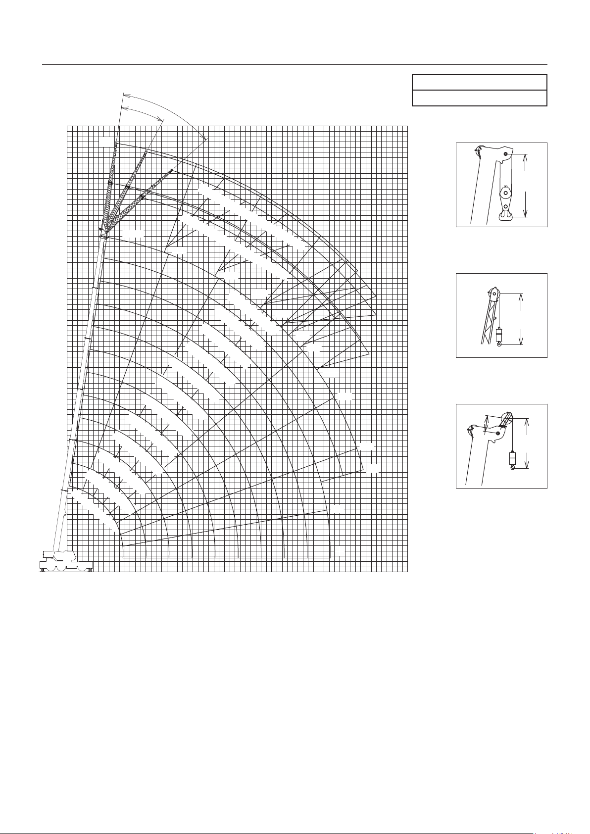
WORKING RANGE
40°
20°
SPEC. SHEET NO. GR-1450E-2-00101/EX-03
Manual offset jib
Counterweight 29.3t
0°
81.5°
35.0m Boom
30.6m Boom
6
1
70°
48.2m Boom
43.8m Boom
39.4m Boom
6
1
.
0
m
.
0
m
B
o
57.0m Boom
52.6m Boom
B
o
o
m
o
m
+
1
0
60°
61.0m Boom
+
.
3
50°
85
BOOM
80
75
70
1
8
.
0
m
J
I
B
m
J
I
B
45°
43°
40°
35°
30°
65
60
55
50
45
40
35
30
JIB
SINGLE TOP
LIFTING HEIGHT (m)
0.6m
Approx.
2.6m
Approx.
3.3m
21.8m Boom
17.4m Boom
13.1m Boom
26.2m Boom
20°
16°
10°
0°
25
20
15
10
5
0
65605550454035302520151050
RADIUS (m)
NOTE: 1.Boom and jib geometry shown are for unloaded condition and machine standing level
on firm supporting surface.
Boom deflection and subsequent radius and boom angle change must be accounted
for when applying load to hook.
Approx.
2.3m
- 5-
Page 6

WORKING RANGE
40°
20°
0°
81.5°
70°
SPEC. SHEET NO. GR-1450E-2-00101/EX-03
Manual offset jib
Counterweight 18.2t
85
80
6
1
.
0
m
B
o
o
m
o
m
+
1
0
58°
55°
61.0m Boom
+
.
3
53°
1
8
.
0
m
J
I
B
m
J
I
B
50°
6
1
.
0
m
B
o
60°
57.0m Boom
75
70
65
60
55
50
BOOM
Approx.
2.6m
JIB
Approx.
3.3m
52.6m Boom
48.2m Boom
43.8m Boom
39.4m Boom
35.0m Boom
30.6m Boom
26.2m Boom
21.8m Boom
17.4m Boom
13.1m Boom
0 5 10 15 20 25 30 35 40 45 50 55 60
40°
32°
30°
21°
20°
10°
0°
RADIUS (m)
45
40
35
30
25
20
15
10
SINGLE TOP
LIFTING HEIGHT (m)
5
0
0.6m
Approx.
2.3m
NOTE: 1.Boom and jib geometry shown are for unloaded condition and machine standing level
on firm supporting surface.
Boom deflection and subsequent radius and boom angle change must be accounted
for when applying load to hook.
- 6-
Page 7

RATED LIFTING CAPACITIES
(
ISO4305
Boom
A
B
2.50
3.00
3.50
4.00
4.50
5.00
5.50
6.00
6.50
7.00
7.50
8.00
9.00
10.00
11.00
12.00
14.00
16.00
18.00
20.00
22.00
24.00
26.00
28.00
30.00
32.00
34.00
36.00
38.00
40.00
42.00
44.00
46.00
48.00
50.00
52.00
54.00
56.00
**Over front with special equipment
*With special equipment
13.1m 17.4m 21.8m 26.2m 30.6m 35.0m 39.4m 43.8m 48.2m 52.6m 57.0m 61.0m
**145.0 90.7 79.0
*110.6 90.7 79.0 37.0
*101.5 90.7 79.0 66.0
93.6 90.1 79.0 66.0 37.0
85.9 83.7 79.0 66.0 48.2
79.3 78.1 75.8 66.0 48.2 35.2
73.5 73.2 71.0 66.0 48.2 35.2
68.3 68.3 66.7 63.5 48.2 38.7
63.7 64.1 63.6 60.5 48.2 37.5 30.1
59.6 60.0 60.2 57.8 48.2 35.9 3
56.0 56.4 56.5 55.3 48.2 35.2 30.1 22.1
52.7 53.1 53.2 52.9 48.0 35.2 29.5 23.9
46.8 47.3 47.5 47.2 44.8 35.2 27.9 23.9 17.2
37.3 41.7 41.9 41.6 41.6 35.2 26.2 22.9 18.9 13.5
37.1 37.3 37.5 37.7 33.2 24.4 22.0 18.9 15.0
33.4 33.5 34.3 33.9 31.5 22.7 21.0 18.4 15.0 12.0
27.8 27.6 28.4 28.0 28.4 20.9 19.2 16.9 15.0 12.0 10.4
ON OUTRIGGERS FULLY EXTENDED 8.2m SPREAD
23.3 24.0 24.3 24.3 19.3 17.1 15.5 14.1 12.0 10.4
21.2 20.2 21.3 20.7 17.8 15.4 14.3 13.1 12.0 10.4
360˚ ROTATION (Unit:×1,000kg)
18.1 17.8 17.
15.4 15.2 14.6 15.2 12.7 11.8 11.2 10.4 9.6
IN METRIC TON
)
SPEC. SHEET NO. GR-1450E-2-00101/EX-03
COUNTERWEIGHT 29.3t
0.1
3 16.5 14.0 12.9 12.1 11.2 10.2
13.0 13.6 13.1 11.7 10.8 10.4 9.8 9.0
11.3 11.9 11.4 10.8 10.1 9.6 9.1 8.4
8.2 10.5 9.9 9.6 9.4 8.8 8.5 7.8
9.3 8.7 9.1 8.6 8.2 8.0 7.3
8.3 7.7 8.0 7.5 7.7 7.4 6.7
6.8 7.1 6.9 7.0 6.6 6.2
6.1 6.3 6.5 6.2 5.8 5.8
5.9 5.8 5.5 5.1 5.1
5.5 5.2 4.9 4.5 4.5
4.6 4.4 3.9 3.9
4.2 3.9 3.4 3.4
3.4 3.0 3.0
3.1 2.6 2.6
2.7 2.2 2.2
1.9 1.9
1.7 1.6
1.3
A :Boom length (m)
B :Load radius (m)
In this table, the thick line which divides strength area and stability area is not shown because the figure of this table is indicated the best
performance at the same boom length among the plural telescopic boom patterns.
-7-
Page 8

RATED LIFTING CAPACITIES
ISO4305
Jib
ON OUTRIGGERS FULLY EXTENDED 8.2m SPREAD
61.0m Boom + 10.3m Manual offset jib 57.0m Boom + 10.3m Manual offset jib
C C
81.5
81
80
79
78
77
76
75
73
70
68
65
63
60
58
55
53
50
48
45
43
40
38
35
33
30
28
25
E
0˚ Tilt 20˚ Tilt 40˚ Tilt
13.2
13.9
15.9
17.2
18.8
20.3
21.9
23.3
26.1
29.8
32.3
35.9
38.0
41.3
43.4
46.4
48.2
50.8
52.2
54.3
55.7
57.7
58.9
60.8
5.5
5.5
5.5
5.5
5.5
5.5
5.5
5.3
5.0
4.5
4.3
4.0
3.7
3.4
3.2
3.0
2.8
2.5
2.2
1.8
1.6
1.3
1.1
0.9
17.3
18.1
19.7
21.3
22.5
23.8
25.3
26.6
29.2
32.9
35.2
38.6
40.8
43.7
45.8
48.6
50.4
52.6
54.0
56.1
57.3
59.2
60.2
61.8
5.5
5.5
5.4
5.3
5.1
4.9
4.8
4.7
4.4
4.1
3.9
3.6
3.5
3.2
3.0
2.8
2.7
2.3
2.0
1.7
1.4
1.2
1.0
0.8
1 1
20.3
21.0
22.4
23.7
25.1
26.3
27.6
28.8
31.2
34.6
36.8
39.9
42.0
45.0
46.7
49.4
51.1
53.1
54.5
56.4
COUNTERW EIGHT 29.3t
360˚ ROTATION
5.2
5.1
4.9
4.8
4.7
4.5
4.4
4.3
4.1
3.8
3.6
3.4
3.3
3.1
2.9
2.7
2.6
2.2
1.9
1.6
SPEC. SHEET NO. GR-1450E-2-00101/EX-03
0˚ Tilt 20˚ Tilt 40˚ Tilt
81.5
81
80
79
78
77
76
75
73
70
68
65
63
60
58
55
53
50
48
45
43
40
38
35
33
30
28
25
E
R W R W R WR W R W R W
11.8
12.5
14.0
15.5
16.9
18.4
19.8
21.1
23.6
27.2
29.4
32.7
35.0
38.0
40.1
42.9
44.6
47.2
48.7
50.7
52.1
54.0
55.2
56.9
57.9
59.5
60.3
61.5
6.2
6.2
6.2
6.2
6.2
6.2
6.2
6.1
5.7
5.2
4.9
4.5
4.3
4.0
3.9
3.6
3.4
3.2
2.9
2.4
2.2
1.8
1.6
1.4
1.2
1.1
0.9
0.8
15.7
16.5
18.0
19.2
20.5
21.8
23.1
24.3
26.7
30.1
32.4
35.6
37.5
40.5
42.5
45.2
46.9
49.1
50.5
52.4
53.6
55.4
56.4
58.0
58.9
60.0
60.9
61.9
6.2
6.2
6.2
6.0
5.8
5.6
5.5
5.3
5.0
4.6
4.4
4.1
3.9
3.7
3.6
3.4
3.3
3.0
2.7
2.3
2.0
1.7
1.5
1.3
1.2
1.0
0.9
0.8
18.6
19.2
20.5
21.7
22.9
24.1
25.3
26.5
28.7
31.9
34.0
37.0
38.9
41.8
43.4
46.1
47.6
49.6
50.9
52.8
5.8
5.8
5.6
5.4
5.3
5.1
5.0
4.9
4.6
4.3
4.1
3.9
3.7
3.6
3.4
3.3
3.2
2.8
2.6
2.2
C
81.5
81
80
79
78
77
76
75
73
70
68
65
63
60
58
55
53
50
48
45
43
40
38
35
33
30
28
25
23
20
E
ON OUTRIGGERS FULLY
52.6m Boom + 10.3m Manual offset jib
R W R W R W R W R W R W
10.3
10.9
12.3
13.7
15.0
16.4
17.6
19.0
21.3
24.8
26.9
30.1
32.1
35.0
36.8
39.5
41.1
43.6
44.9
46.8
48.1
49.9
51.1
52.9
53.8
55.3
56.1
57.3
57.9
58.8
7.2
7.2
7.2
7.2
7.2
7.2
7.2
7.2
6.8
6.2
5.9
5.4
5.2
4.8
4.5
4.2
4.0
3.8
3.4
2.9
2.7
2.3
2.1
1.8
1.6
1.4
1.3
1.1
1.0
0.9
14.3
14.9
16.3
17.6
18.8
19.7
21.1
22.2
24.4
27.7
29.7
32.7
34.6
37.4
39.2
41.6
43.2
45.4
46.6
48.5
49.6
51.2
52.3
54.0
54.9
56.1
56.8
57.7
7.2
7.2
7.2
7.1
6.9
6.6
6.4
6.2
5.9
5.4
5.2
4.9
4.7
4.4
4.2
4.0
3.8
3.5
3.2
2.7
2.5
2.1
1.9
1.7
1.5
1.3
1.2
1.1
1 2
17.3
17.9
19.1
20.2
21.4
22.5
23.5
24.6
26.7
29.6
31.5
34.3
36.0
38.7
40.4
42.6
44.1
46.0
47.2
48.9
COUNTERW EIGHT 29.3t
6.8
6.7
6.5
6.3
6.1
6.0
5.8
5.7
5.4
5.0
4.8
4.6
4.4
4.2
4.1
3.8
3.7
3.4
3.1
2.6
EXTENDED 8.2m SPREAD
360˚ ROTATION
C
81.5
81
80
79
78
77
76
75
73
70
68
65
63
60
58
55
53
50
48
45
43
40
38
35
33
30
28
25
23
20
E
35.0m Boom + 10.3m Manual offset jib
0˚ Tilt 20˚ Tilt 40˚ Tilt0˚ Tilt 20˚ Tilt 40˚ Tilt
10.6
10.5
10.2
10.0
9.7
9.5
9.3
9.1
8.7
8.2
7.9
7.6
7.4
7.1
6.9
6.7
6.5
6.4
6.3
6.1
6.1
6.0
5.9
5.9
5.8
5.4
5.2
5.0
11.3
12.9
15.2
16.7
18.9
20.3
22.4
23.7
25.7
26.8
28.6
29.7
31.4
32.4
33.9
34.9
36.1
36.9
38.1
38.7
39.7
40.3
41.0
14.1
13.2
12.2
11.6
10.8
10.4
9.9
9.6
9.1
8.7
8.3
8.0
7.7
7.5
7.2
6.9
6.4
6.1
5.7
5.4
5.2
5.0
4.8
8.9
9.3
10.1
10.9
11.9
12.6
13.3
14.1
15.6
17.9
19.3
21.4
22.8
24.8
26.0
27.8
29.0
30.6
31.7
33.2
34.1
35.5
36.3
37.5
38.1
39.1
39.7
40.4
11.3
11.7
12.5
13.2
14.0
14.8
15.5
16.2
17.6
19.6
21.0
22.9
24.2
26.0
27.2
28.9
29.9
31.5
32.4
33.8
7.3
7.2
7.1
7.0
6.9
6.9
6.8
6.7
6.5
6.3
6.2
6.1
6.0
5.9
5.8
5.8
5.7
5.7
5.7
5.6
C :Loaded boom angle (˚)
R :Load radius (m)
W:Rated lifting capacity (Unit:×1,000kg)
E :Number of parts of line
-8-
Page 9

RATED LIFTING CAPACITIES
ISO4305
Jib
ON OUTRIGGERS FULLY EXTENDED 8.2m SPREAD
C
81.5
81
80
79
78
77
76
75
73
70
68
65
63
60
58
55
53
50
48
45
43
40
38
35
E
61.0m Boom + 18.0m Manual offset jib
15.1
16.1
17.7
19.6
21.5
23.0
24.9
26.6
29.7
33.9
36.7
40.6
43.3
46.8
49.2
52.4
54.3
56.8
58.6
60.8
62.3
3.7
3.7
3.7
3.7
3.7
3.7
3.7
3.7
3.7
3.4
3.3
3.0
2.9
2.6
2.5
2.3
2.1
1.7
1.5
1.1
0.9
22.4
23.0
25.0
26.7
28.3
29.8
31.4
32.7
35.5
39.3
41.9
45.6
47.9
51.3
53.3
56.3
58.0
60.1
61.7
63.7
64.9
3.7
3.7
3.7
3.7
3.6
3.5
3.4
3.3
3.1
2.9
2.8
2.6
2.5
2.4
2.2
2.1
1.9
1.5
1.3
1.0
0.8
1 1
27.2
28.2
29.6
31.2
32.6
34.0
35.4
36.6
39.3
42.8
45.1
48.2
50.5
53.3
55.3
57.8
59.1
60.9
62.2
64.1
COUNTERW EIGHT 29.3t
360˚ ROTATION
C
3.2
3.2
3.1
3.1
3.0
3.0
3.0
2.9
2.9
2.7
2.6
2.4
2.4
2.2
2.2
2.0
1.7
1.3
1.1
0.9
81.5
81
80
79
78
77
76
75
73
70
68
65
63
60
58
55
53
50
48
45
43
40
38
35
E
SPEC. SHEET NO. GR-1450E-2-00101/EX-03
57.0m Boom + 18.0m Manual offset jib
0˚ Tilt 20˚ Tilt 40˚ Tilt0˚ Tilt 20˚ Tilt 40˚ Tilt
R W R W R WR W R W R W
13.3
14.1
15.7
17.3
19.0
20.6
22.2
23.8
26.9
31.3
34.0
37.7
40.2
43.6
45.9
49.0
50.9
53.5
55.0
57.3
58.8
60.8
62.1
64.0
4.0
4.0
4.0
4.0
4.0
4.0
4.0
4.0
4.0
4.0
3.8
3.5
3.4
3.1
3.0
2.8
2.6
2.3
2.0
1.7
1.5
1.2
1.0
0.8
20.2
21.1
22.7
24.2
25.7
27.1
28.6
30.0
32.7
36.6
39.1
42.5
44.7
48.0
50.0
52.8
54.6
56.8
58.2
60.2
61.4
63.1
64.3
4.0
4.0
4.0
3.9
3.8
3.7
3.7
3.6
3.5
3.3
3.2
3.0
2.9
2.8
2.7
2.5
2.4
2.0
1.8
1.5
1.3
1.0
0.9
24.8
25.6
27.1
28.3
29.8
31.0
32.4
33.6
36.0
39.5
41.6
44.8
46.8
49.8
51.5
54.1
55.5
57.4
58.6
60.4
3.3
3.3
3.3
3.2
3.2
3.1
3.1
3.1
3.0
2.9
2.8
2.8
2.7
2.6
2.5
2.4
2.2
1.9
1.6
1.3
C
81.5
81
80
79
78
77
76
75
73
70
68
65
63
60
58
55
53
50
48
45
43
40
38
35
33
30
28
25
23
20
E
52.6m Boom + 18.0m Manual offset jib
12.0
12.8
14.3
15.9
17.3
18.8
20.1
21.7
24.7
28.7
31.2
34.8
37.0
40.3
42.3
45.3
47.1
49.7
51.3
53.6
55.1
57.1
58.5
60.4
61.7
63.3
4.7
4.7
4.7
4.7
4.7
4.7
4.7
4.7
4.7
4.7
4.5
4.2
4.0
3.8
3.6
3.3
3.2
2.8
2.5
2.1
1.9
1.6
1.4
1.1
1.0
0.8
18.7
19.4
20.9
22.2
23.5
24.9
26.2
27.5
30.0
33.7
36.1
39.4
41.4
44.5
46.4
49.3
51.0
53.2
54.5
56.4
57.7
59.5
60.6
62.1
63.0
4.4
4.4
4.3
4.2
4.1
4.0
3.9
3.9
3.7
3.6
3.5
3.3
3.2
3.1
3.1
3.0
2.9
2.5
2.2
1.8
1.6
1.4
1.2
1.0
0.9
1 1
ON OUTRIGGERS FULLY EXTENDED 8.2m SPREAD
COUNTERW EIGHT 29.3t
360˚ ROTATION
35.0m Boom + 18.0m Manual offset jib
0˚ Tilt 20˚ Tilt 40˚ Tilt0˚ Tilt 20˚ Tilt 40˚ Tilt
R W R W R WR W R W R W
7.4
8.0
9.0
10.2
11.1
12.1
13.0
14.0
15.8
18.7
20.3
22.9
24.6
27.1
28.7
30.9
32.4
34.5
35.9
37.7
39.0
40.7
41.8
43.3
44.3
45.7
46.5
47.6
48.3
49.1
23.2
23.8
25.3
26.5
27.7
28.9
30.1
31.2
33.4
36.7
38.8
41.6
43.5
46.3
48.1
50.6
52.0
53.8
55.0
56.7
3.4
3.4
3.4
3.3
3.3
3.3
3.2
3.2
3.1
3.0
3.0
2.9
2.9
2.8
2.8
2.8
2.7
2.3
2.0
1.7
C
81.5
81
80
79
78
77
76
75
73
70
68
65
63
60
58
55
53
50
48
45
43
40
38
35
33
30
28
25
23
20
E
6.4
6.4
6.4
6.4
6.4
6.4
6.4
6.4
6.4
6.3
6.0
5.6
5.3
5.0
4.8
4.6
4.4
4.2
4.1
3.9
3.8
3.7
3.6
3.5
3.4
3.3
3.3
3.2
3.2
3.1
13.3
13.7
14.7
15.7
16.6
17.5
18.5
19.3
21.2
22.7
25.4
27.8
29.4
31.6
33.0
35.0
36.5
38.3
39.6
41.1
42.2
43.7
44.5
45.8
46.5
47.5
48.1
48.8
5.4
5.3
5.2
5.1
5.0
4.8
4.7
4.6
4.5
4.2
4.1
3.9
3.8
3.6
3.6
3.4
3.4
3.3
3.3
3.2
3.2
3.1
3.1
3.1
3.1
3.1
3.1
3.1
18.0
18.4
19.3
20.1
20.9
21.7
22.5
23.4
24.9
27.1
28.5
30.7
32.0
34.0
35.3
37.1
38.1
39.7
40.7
42.0
3.7
3.7
3.6
3.6
3.6
3.5
3.5
3.5
3.4
3.3
3.2
3.2
3.2
3.1
3.1
3.1
3.0
3.0
3.0
3.0
C :Loaded boom angle (˚)
R :Load radius (m)
W:Rated lifting capacity (Unit:×1,000kg)
E :Number of parts of line
-9-
Page 10

RATED LIFTING CAPACITIES
ISO4305
Jib
ON OUTRIGGERS FULLY EXTENDED 8.2m SPREAD
C
81.5
81
80
79
78
77
76
75
73
70
68
65
63
60
58
55
53
50
48
45
E
61.0m Boom + 10.3m Manual offset jib
13.2
13.9
15.9
17.2
18.8
20.3
21.9
23.3
26.1
29.8
32.3
35.9
37.8
40.4
42.2
44.8
46.5
49.0
5.5
5.5
5.5
5.5
5.5
5.5
5.5
5.3
5.0
4.5
4.3
4.0
3.6
2.7
2.3
1.7
1.4
1.0
17.3
18.1
19.7
21.3
22.5
23.8
25.3
26.6
29.2
32.9
35.2
38.6
46.7
43.0
44.6
47.3
48.8
51.1
5.5
5.5
5.4
5.3
5.1
4.9
4.8
4.7
4.4
4.1
3.9
3.6
3.2
2.5
2.1
1.5
1.2
0.9
1 1
20.3
21.0
22.4
23.7
25.1
26.3
27.6
28.8
31.2
34.6
36.8
39.9
41.8
44.2
45.9
48.3
49.8
51.9
COUNTERWEIGHT 18.2t
360˚ ROTATION
C
5.2
5.1
4.9
4.8
4.7
4.5
4.4
4.3
4.1
3.8
3.6
3.4
3.0
2.3
1.9
1.5
1.2
0.8
81.5
81
80
79
78
77
76
75
73
70
68
65
63
60
58
55
53
50
48
45
E
SPEC. SHEET NO. GR-1450E-2-00101/EX-03
57.0m Boom + 10.3m Manual offset jib
0˚ Tilt 20˚ Tilt 40˚ Tilt0˚ Tilt 20˚ Tilt 40˚ Tilt
R W R W R WR W R W R W
11.8
12.5
14.0
15.5
16.9
18.4
19.8
21.1
23.6
27.2
29.4
32.7
35.0
38.7
40.3
42.8
44.4
46.6
48.2
50.3
6.2
6.2
6.2
6.2
6.2
6.2
6.2
6.1
5.7
5.2
4.9
4.5
4.3
3.5
3.0
2.4
2.0
1.6
1.3
0.9
15.7
16.5
18.0
19.2
20.5
21.8
23.1
24.3
26.7
30.1
32.4
35.6
37.5
40.0
41.7
44.0
45.6
47.8
49.2
51.3
6.2
6.2
6.2
6.0
5.8
5.6
5.5
5.3
5.0
4.6
4.4
4.1
3.9
3.2
2.7
2.2
1.8
1.4
1.2
0.8
18.6
19.2
20.5
21.7
22.9
24.1
25.3
26.5
28.7
31.9
34.0
37.0
38.7
41.2
42.6
45.1
46.4
48.6
49.9
51.8
5.8
5.8
5.6
5.4
5.3
5.1
5.0
4.9
4.6
4.3
4.1
3.9
3.7
3.0
2.6
2.1
1.7
1.3
1.1
0.8
C
81.5
81
80
79
78
77
76
75
73
70
68
65
63
60
58
55
53
50
48
45
43
40
38
35
33
30
28
25
23
20
E
52.6m Boom + 10.3m Manual offset jib
10.3
10.9
12.3
13.7
15.0
16.4
17.6
19.0
21.3
24.8
26.9
30.1
32.1
35.6
37.1
39.5
41.0
43.2
44.6
46.7
47.2
49.2
7.2
7.2
7.2
7.2
7.2
7.2
7.2
7.2
6.8
6.2
5.9
5.4
5.2
4.3
3.7
3.0
2.5
2.0
1.7
1.3
1.1
0.8
14.3
14.9
16.3
17.6
18.8
19.7
21.1
22.2
24.4
27.7
29.7
32.7
34.6
37.0
38.5
40.9
42.3
44.6
45.8
47.7
49.0
7.2
7.2
7.2
7.1
6.9
6.6
6.4
6.2
5.9
5.4
5.2
4.9
4.7
3.8
3.3
2.7
2.3
1.8
1.6
1.2
1.0
1 2
ON OUTRIGGERS FULLY EXTENDED 8.2m SPREAD
17.3
17.9
19.1
20.2
21.4
22.5
23.5
24.6
26.7
29.6
31.5
34.3
36.0
38.3
39.7
41.9
43.2
45.3
46.5
48.3
COUNTERWEIGHT 18.2t
360˚ ROTATION
C
6.8
6.7
6.5
6.3
6.1
6.0
5.8
5.7
5.4
5.0
4.8
4.6
4.4
3.6
3.1
2.5
2.2
1.7
1.5
1.1
81.5
81
80
79
78
77
76
75
73
70
68
65
63
60
58
55
53
50
48
45
43
40
38
35
33
30
28
25
23
20
E
35.0m Boom + 10.3m Manual offset jib
0˚ Tilt 20˚ Tilt 40˚ Tilt0˚ Tilt 20˚ Tilt 40˚ Tilt
R W R W R WR W R W R W
11.3
12.9
15.2
16.7
18.9
20.3
22.4
23.7
25.7
26.8
28.5
29.6
31.2
32.2
33.6
34.5
35.9
36.7
37.8
38.5
39.5
40.1
40.4
14.1
13.2
12.2
11.6
10.8
10.4
9.9
9.6
9.1
8.3
7.2
6.7
5.9
5.5
4.9
4.6
4.2
4.0
3.6
3.5
3.2
3.1
2.9
8.9
9.3
10.1
10.9
11.9
12.6
13.3
14.1
15.6
17.9
19.3
21.4
22.8
24.8
26.0
27.8
29.0
30.6
31.8
33.1
34.0
35.3
36.1
37.3
38.0
39.0
39.5
40.3
10.6
10.5
10.2
10.0
9.7
9.5
9.3
9.1
8.7
8.2
7.9
7.6
7.4
7.1
6.9
6.7
6.5
6.4
6.1
5.5
5.1
4.6
4.3
4.0
3.8
3.5
3.3
3.1
11.3
11.7
12.5
13.2
14.0
14.8
15.5
16.2
17.6
19.6
21.0
22.9
24.2
26.0
27.2
28.9
29.9
31.5
32.4
33.7
7.3
7.2
7.1
7.0
6.9
6.9
6.8
6.7
6.5
6.3
6.2
6.1
6.0
5.9
5.8
5.8
5.7
5.7
5.7
5.3
C :Loaded boom angle (˚)
R :Load radius (m)
W:Rated lifting capacity (Unit:×1,000kg)
E :Number of parts of line
-
10
-
Page 11

RATED LIFTING CAPACITIES
ISO4305
Jib
ON OUTRIGGERS FULLY EXTENDED 8.2m SPREAD
C
81.5
81
80
79
78
77
76
75
73
70
68
65
63
60
58
55
53
50
48
E
61.0m Boom + 18.0m Manual offset jib
15.1
16.1
17.7
19.6
21.5
23.0
24.9
26.6
29.7
33.9
36.7
40.6
42.6
45.5
47.4
50.2
52.2
3.7
3.7
3.7
3.7
3.7
3.7
3.7
3.7
3.7
3.4
3.3
3.0
2.6
1.9
1.5
1.0
0.8
22.4
23.0
25.0
26.7
28.3
29.8
31.4
32.7
35.5
39.3
41.9
45.5
47.4
50.0
51.6
54.3
3.7
3.7
3.7
3.7
3.6
3.5
3.4
3.3
3.1
2.9
2.8
2.6
2.1
1.6
1.2
0.8
1 1
27.2
28.2
29.6
31.2
32.6
34.0
35.4
36.6
39.3
42.8
45.1
48.2
49.7
52.1
53.8
COUNTERWEIGHT 18.2t
360˚ ROTATION
C
3.2
3.2
3.1
3.1
3.0
3.0
3.0
2.9
2.9
2.7
2.6
2.2
1.9
1.4
1.1
81.5
81
80
79
78
77
76
75
73
70
68
65
63
60
58
55
53
50
48
E
SPEC. SHEET NO. GR-1450E-2-00101/EX-03
57.0m Boom + 18.0m Manual offset jib
0˚ Tilt 20˚ Tilt 40˚ Tilt0˚ Tilt 20˚ Tilt 40˚ Tilt
R W R W R WR W R W R W
13.3
14.1
15.7
17.3
19.0
20.6
22.2
23.8
26.9
31.3
34.0
37.7
40.2
42.8
44.7
47.4
49.1
51.7
4.0
4.0
4.0
4.0
4.0
4.0
4.0
4.0
4.0
4.0
3.8
3.5
3.3
2.5
2.1
1.6
1.3
0.9
20.2
21.1
22.7
24.2
25.7
27.1
28.6
30.0
32.7
36.6
39.1
42.5
44.6
47.1
48.8
51.2
52.9
4.0
4.0
4.0
3.9
3.8
3.7
3.7
3.6
3.5
3.3
3.2
3.0
2.7
2.1
1.8
1.3
1.1
24.8
25.6
27.1
28.3
29.8
31.0
32.4
33.6
36.0
39.5
41.6
44.8
46.5
49.0
50.6
52.8
54.2
3.3
3.3
3.3
3.2
3.2
3.1
3.1
3.1
3.0
2.9
2.8
2.8
2.4
1.9
1.6
1.2
0.9
C
81.5
81
80
79
78
77
76
75
73
70
68
65
63
60
58
55
53
50
48
45
43
40
38
35
33
30
28
25
23
20
E
52.6m Boom + 18.0m Manual offset jib
12.0
12.8
14.3
15.9
17.3
18.8
20.1
21.7
24.7
28.7
31.2
34.8
36.9
39.5
41.4
44.1
45.8
48.5
50.2
4.7
4.7
4.7
4.7
4.7
4.7
4.7
4.7
4.7
4.7
4.5
4.2
4.0
3.1
2.7
2.1
1.7
1.3
1.0
18.7
19.4
20.9
22.2
23.5
24.9
26.2
27.5
30.0
33.7
36.1
39.4
41.4
44.1
45.8
48.2
49.7
52.1
53.5
4.4
4.4
4.3
4.2
4.1
4.0
3.9
3.9
3.7
3.6
3.5
3.3
3.2
2.6
2.2
1.7
1.4
1.1
0.8
1 1
ON OUTRIGGERS FULLY EXTENDED 8.2m SPREAD
23.2
23.8
25.3
26.5
27.7
28.9
30.1
31.2
33.4
36.7
38.8
41.6
43.5
46.3
47.7
49.8
51.3
53.1
COUNTERWEIGHT 18.2t
360˚ ROTATION
C
3.4
3.4
3.4
3.3
3.3
3.3
3.2
3.2
3.1
3.0
3.0
2.9
2.9
2.3
2.0
1.5
1.3
0.9
81.5
81
80
79
78
77
76
75
73
70
68
65
63
60
58
55
53
50
48
45
43
40
38
35
33
30
28
25
23
20
E
35.0m Boom + 18.0m Manual offset jib
0˚ Tilt 20˚ Tilt 40˚ Tilt0˚ Tilt 20˚ Tilt 40˚ Tilt
R W R W R WR W R W R W
7.4
8.0
9.0
10.2
11.1
12.1
13.0
14.0
15.8
18.7
20.3
22.9
24.6
27.1
28.7
30.9
32.4
34.5
35.9
37.7
39.0
40.7
41.7
43.2
44.3
45.5
46.3
47.4
48.1
48.9
6.4
6.4
6.4
6.4
6.4
6.4
6.4
6.4
6.4
6.3
6.0
5.6
5.3
5.0
4.8
4.6
4.4
4.2
4.1
3.9
3.8
3.7
3.4
3.1
2.9
2.7
2.5
2.3
2.2
2.1
13.3
13.7
14.7
15.7
16.6
17.5
18.5
19.3
21.2
22.7
25.4
27.8
29.4
31.6
33.0
35.0
36.5
38.3
39.6
41.1
42.2
43.7
44.5
45.7
46.4
47.4
47.9
48.6
5.4
5.3
5.2
5.1
5.0
4.8
4.7
4.6
4.5
4.2
4.1
3.9
3.8
3.6
3.6
3.4
3.4
3.3
3.3
3.2
3.2
3.1
3.1
2.8
2.7
2.5
2.3
2.2
18.0
18.4
19.3
20.1
20.9
21.7
22.5
23.4
24.9
27.1
28.5
30.7
32.0
34.0
35.3
37.1
38.1
39.7
40.7
42.0
3.7
3.7
3.6
3.6
3.6
3.5
3.5
3.5
3.4
3.3
3.2
3.2
3.2
3.1
3.1
3.1
3.0
3.0
3.0
3.0
C :Loaded boom angle (˚)
R :Load radius (m)
W:Rated lifting capacity (Unit:×1,000kg)
E :Number of parts of line
-11-
Page 12

RATED LIFTING CAPACITIES
SPEC. SHEET NO. GR-1450E-2-00101/EX-03
NOTES FOR "ON OUTRIGGERS" TABLE
1. Rated lifting capacities shown in the table are based on condition that crane is set on firm level surface. Those above thick lines are
based on crane strength and those below, on its stability. (Excluding the table shown in page 7)
2. Rated lifting capacities based on crane stability are according to ISO4305.
3. The mass of the hook (1,080 kg for 100t capacity, 610 kg for 45t capacity, 300 kg for 7.2 t capacity), slings and all similarly used
load handling devices must be considered as part of the load and must be deducted from the lifting capacities.
4. For rated lifting capacity of single top, reduce the rated lifting capacities of relevant boom according to a weight reduction for
auxiliary load handling equipment. Capacities of single top shall not exceed 7,200 kg including main boom hook mass and the net
capacity must be so reduced.
5. Standard number of parts of line for each boom length is as shown below. Load per line should not surpass 70.6 kN {7,200 kgf} for
main winch and auxiliary winch.
Boom length
Tele.1 0 0 0 0 0 0 45 0 0 0 45 0
Tele.2 0 0 45 0 0 0 45 45 0 0 45 45
Tele.3 0 0 0 45 0 0 0 45 0 45 45 45
Tele.4 0 0 0 0 0 45 0 0 45 45 0 45
Tele.5 0 45 0 0 90 45 0 0 90 45 0 0
Number of
parts of line
Boom length
Tele.1 0 0 90 45 0 45 90 0 0 90 45
Tele.2 0 45 45 45 0 45 45 45 0 45 45
Tele.3 0 45 45 45 45 45 45 45 90 45 45
Tele.4 90 45 0 45 90 45 45 45 90 45 45
Tele.5 90 45 0 0 90 45 0 90 90 45 90
Number of
parts of line
Boom length
Tele.1 0 45 90 90 0 90 45 45 90 90 100
Tele.2 45 45 90 45 90 90 90 90 90 90 100
Tele.3 90 45 45 45 90 90 90 90 90 90 100
Tele.4 90 90 45 45 90 45 90 90 90 90 100
Tele.5 90 90 45 90 90 45 45 90 45 90 100
Number of
parts of line
13.1m 26.2m21.8m17.4m
Telescoping conditions (%)
22 6 14 14 6 6 12 12 6 6 10 9
35.0m30.6m
Telescoping conditions (%)
6 6 8 8 6 6 7 6 4 6 6
Telescoping conditions (%)
4 4 4 4 4 4 4 4 4 4 4
39.4m
57.0m52.6m48.2m43.8m 61.0m
The lifting capacity data stowed in the AUTOMATIC MOMENT LIMITER (AML) is based on the standard number of parts of line
listed in the chart.
Maximum lifting capacity is restricted by the number of parts of line of AUTOMATIC MOMENT LIMITER (AML).
-
12
-
Page 13

RATED LIFTING CAPACITIES
ISO4305
ON-RUBBER STATIONARY (Unit: x 1,000kg)
Over front and rear 360˚ Rotation
C C C C C
78
76
74
72
71
69
67
65
63
61
59
57
53
49
44
10.0
10.0
10.0
10.0
10.0
10.0
9.5
8.4
7.4
6.5
5.8
5.1
3.7
2.4
1.5
B
2.50
3.00
3.50
4.00
4.50
5.00
5.50
6.00
6.50
7.00
7.50
8.00
9.00
10.00
11.00
A
13.1m 17.4m 21.8m 13.1m 17.4m 21.8m
C
73
71
68
66
63
61
58
55
52
49
46
43
35
10.0
10.0
10.0
10.0
10.0
9.2
8.0
6.9
5.9
5.1
4.3
3.3
1.8
12.00
D
Tele.1
Tele.2
Tele.3
Tele.4
Tele.5
0
0
0
0
0
0
0
0
0
45
E
SPEC. SHEET NO. GR-1450E-2-00101/EX-03
WITHOUT COUNTERWEIGHT
80
79
78
76
75
74
72
71
69
68
67
65
62
59
56
52
Telescoping conditions(%)
10.0
10.0
10.0
10.0
10.0
10.0
10.0
9.1
8.1
7.4
6.6
5.9
4.6
3.4
2.4
1.7
0
0
0
0
90
73
71
68
66
63
61
58
55
52
4
0
0
0
0
0
10.0
10.0
9.9
8.0
6.4
5.1
4.0
3.0
2.1
78
76
74
72
71
69
67
65
63
61
59
57
10.0
10.0
10.0
9.7
8.1
6.8
5.7
4.7
3.9
3.1
2.4
1.7
564750400 59
0
0
0
0
45
80
79
78
76
75
74
72
71
69
68
67
65
62
10.0
10.0
10.0
10.0
9.0
7.7
6.6
5.6
4.8
4.1
3.3
2.7
1.7
0
0
0
0
90
NOTE: The lifting capacity data stowed in the AUTOMATIC MOMENT LIMITER (AML) is based on
the standard number of parts of line listed in the chart.
Standard number of parts of line for on-rubber operation should be according to the chart.
WORKING AREA
Over
Front
360˚ Over
Rear
10˚10˚
A :Boom length (m)
B :Load radius (m)
C :Loaded boom angle (˚)
D :Minimum boom angle (˚)
for indicated length (no load)
E :Number of parts of line
- 13-
Page 14

RATED LIFTING CAPACITIES
ISO4305
SPEC. SHEET NO. GR-1450E-2-00101/EX-03
NOTES FOR "ON RUBBER" TABLES
1. Rated lifting capacities shown in the table are based on condition that crane is set on firm level surface, with suspension lock
applied. Those above thick lines are based on tire capacity and those below, on crane stability. They are based on actual load
radius increased by tire deformation and boom deflection.
2. Rated lifting capacities based on crane stability are according to ISO4305.
3. The mass of the hook (1,080 kg for 100t capacity, 610 kg for 45t capacity, 300 kg for 7.2t capacity), slings and all similarly used load
handling devices must be considered as part of the load and must be deducted from the lifting capacities.
4. For rated lifting capacity of single top, reduce the rated lifting capacities of relevant boom according to weight reductions for auxiliary
load handling equipment. Capacities of single top shall not exceed 7,200 kg including main hook.
5. On-rubber lifting with "jib" is not permitted. Maximum permissible boom length is 21.8 m.
6. Tires should be inflated to their correct air pressure of 650kPa.
7. Standard number of parts of line for on-rubber operation should be according to the following table.
Load per line should not surpass 70.6 kN {7,200 kgf} for main winch and auxiliary winch.
Boom length
Tele.1
Tele.2
Tele.3
Tele.4
Tele.5
Number of parts of line
The lifting capacity data stowed in the AUTOMATIC MOMENT LIMITER (AML) is based on the standard number of parts of line
listed in the chart.
Maximum lifting capacity is restricted by the number of parts of line of AUTOMATIC MOMENT LIMITER (AML).
13.1m 17.4m 21.8m
Telescoping conditions (%)
0
0
0
0
0
4
0
0
0
0
45
4
0
0
0
0
90
4
WORKING AREA
Over
Front
360˚ Over
Rear
10˚10˚
Over front and rear operation shall be performed within 10 degrees.
- 14-
Page 15

DIMENSION
OPTIONAL WEIGHT 11.1t
3,500
SPEC. SHEET NO. GR-1450E-2-00101/EX-03
570
4,165
4,860
2,990
5,500
8,200
7,300
2,599
3,315
8,045
17.4°
12.6°
13,050〜61,000
4,5054,520
2,400
1,1002,010
10,155
4,000
16,190
Note: Dimension is with boom angle at -1.5 degree.
4,600
16.2°
11.9°
2,1452,000
Axle Weight Distribution Chart Unit : kg
Kilograms
GVW 1st 2nd 3rd
Base machine
Remove:
1.7.2 t hook block
2.100t hook block
3.Counterweight 11,100kg
4.Counterweight 18,200kg
5.Front outrigger unit
6.Rear outrigger unit
7.Auxiliary Winch & wire rope
8.Top jib
9.Base jib
10.Boom
90,805
-300
-1,080
-11,120
-18,160
-4,481
-4,481
-1,202
-387
-1,063
-15,624
28,701
-421
-1,771
3,351
5,473
-5,742
2,279
490
-460
-1,838
-19,547
30,814
61
346
-7,236
-11,816
630
-3,380
-846
37
388
1,962
31,290
61
346
-7,236
-11,816
630
-3,380
-846
37
388
1,962
3,785
Add:
45t hook block
+610
-
15
-
+1,000
-195
-195
Page 16

Specifications are subject to change without notice.
(International Division)
4-12, Kamezawa 2-chome,
Sumida-ku, Tokyo 130-0014, Japan
Te l : 81-(0)3-3621-7750
Fax : 81-(0)3-3621-7785
URL
http://www.tadano-global.com
E-mail
tdnihq@tadano.co.jp
Printed in Japan
GR-1450EX-2013-11-1
 Loading...