

Page 1

INSTRUCTIONS FOR USE
Automated Blood Coagulation Analyzer
CA-500 series
CHAPTER 1: Introduction
CHAPTER 2: Safety Information
CHAPTER 3: Design and Function
CHAPTER 4: Installation Environment
CHAPTER 5: Operation
CHAPTER 6: Display and Processing of
Analysis Results
CHAPTER 7: Output
CHAPTER 8: Quality Control
CHAPTER 9: Setting Standard Curve
CHAPTER 10: Instrument Setup
CHAPTER 11: Maintenance and Supplies
Replacement
CHAPTER 12: Troubleshooting
CHAPTER 13: Functional Description
CHAPTER 14: Technical Information
CHAPTER 15: Index
CHAPTER 16: Appendix (A)
SYSMEX CORPORATION
KOBE, JAPAN
Copyright © 2001-2004 by SYSMEX CORPORATION
All rights reserved. No part of this Instruction for Use may be
reproduced in any form or by any means whatsoever without
prior written permission of SYSMEX CORPORATION.
Code No. 461-2655-0
PRINTED IN JAPAN
Date of Last Revision: April 2004
Software version 00-17 and onwards
Page 2

Table of Contents
1. Introduction .........................................................1-1
1.1 Introduction ........................... ............................................. .....1-1
1.2 Explanation of Signs ...............................................................1-3
1.3 Names .................................................................................... 1-4
1.4 Serial Number..........................................................................1-4
1.5 Revision History ......................................................................1-4
2. Safety Information ...............................................2-1
2.1 Specified Conditions of Use ................................................... 2-1
2.2 General Information ................................................................2-1
2.3 Installation Location ................................................................2-3
2.4 Avoidance of Infections .......................................................... 2-3
2.5 Handling of Reagents ............................................................. 2-4
2.6 Maintenance of the Instrument ............................................... 2-5
2.7 Disposal of Materials .............................................................. 2-5
2.8 Markings on the Instrument .................................................... 2-6
2.9 Personnel ............................................................................... 2-8
2.10 Storage Condition (Transportation)......................................... 2-8
3. Design and Function ........................................... 3-1
3.1 Overview ......................... ................ ................ ................ ........ 3-1
3.2 Operation Flow ....................................................................... 3-8
4. Installation Environment ....................................4-1
4.1 Installation and Relocation ..................................................... 4-1
4.2 Installation Location ................................................................4-1
4.3 Basic Instrument Settings .......................................................4-3
Revised November 2003 - 2.0_en
Sysmex CA-500 series I
Page 3

5. Operation ..............................................................5-1
5.1 Display Screens and Operation Keys .....................................5-1
5.2 Menu Tree ............................. ... ... ... ... .....................................5-3
5.3 Types of Alarm ................................... .... ... ... ... .... ....................5-5
5.4 Inspection before Turning ON the Power ...............................5-5
5.5 Turn ON the Power .................................................................5-7
5.6 Prepare Reagents ...................................................................5-8
5.7 Set Reaction Tubes ..............................................................5-13
5.8 Confirm Standard Curve .......................................................5-14
5.9 Execute Quality Control ........................................................5-15
5.10 Prepare Samples ..................................................................5-15
5.11 Set Sample Nos. ...................................................................5-19
5.12 Manual Inquiry ...................................................................... 5-22
5.13 Automatic Inquiry ................................................... ...............5-22
5.14 Start Analysis ......................... ... ... ... ... .... ... ... ... ......................5-24
5.15 Automatic Sensitivity Adjustment of the Detector
(for CA-530, CA-540, CA-550 and CA-560 only) ..................5-26
5.16 Display Analysis Result ........................................................5-27
5.17 Interrupt Analysis ..................................................................5-28
5.18 Add Samples ........................................................................5-29
5.19 Analyze STAT Sample .......................................................... 5-30
5.20 Emergency Stop ................................................................... 5-31
5.21 Shutdown ........................................................ ...................... 5-33
6. Display and Processing of Analysis Results ....6-1
6.1 List Display/Graphic Display ...................................................6-1
6.2 Search .................................................................................... 6-6
6.3 Sort in Sequence of Sample ID Nos. and Analyses ........... ... . 6-9
6.4 Select Display ......................................................................... 6-9
6.5 Edit ID No. ............................................................................6-11
6.6 Deletion ................................................................................. 6-12
7. Output ...................................................................7-1
7.1 Automatic Printout of Analysis Data .......................................7-1
7.2 Output of Analysis Data ..........................................................7-1
7.3 Example of Printout ................................................................7-3
8. Quality Control .....................................................8-1
8.1 Quality Control Methods .........................................................8-1
8.2 QC File Setting .......................................................................8-1
8.3 Execute Quality Control ..........................................................8-5
8.4 Display QC Charts .................................................................. 8-5
8.5 Delete QC File ........................................................................8-7
8.6 Delete QC Data ......................................................................8-8
8.7 Print QC data .......................................................................... 8-9
II Sysmex CA-500 series
Revised January 2003 - 2.0_en
Page 4

9. Setting Standard Curve ...................................... 9-1
9.1 Display Standard Curve ..................... ... .... ... ... ... ... .... ... ... ... .... . 9-1
9.2 Standard Curve Analysis ................ ...... .... ... ... ... ... .... ... ... ... .... . 9-3
9.3 INR Manual Dilution Analysis ................................................ . 9-6
9.4 Manual Entry ..........................................................................9-8
9.5 Set Reagent Information ........................... ................ .............. 9-9
9.6 Set Calculation Parameters .................................................. 9-10
9.7 Print Standard Curve ............................................................ 9-13
10. Instrument Setup ...............................................10-1
10.1 General Information ..............................................................10-1
10.2 Setup of Automatic Transfer/Printout ................................... 10-2
10.3 Judgment on Analysis Result ............................................... 10-4
10.4 Replication Range .......... ... ... ... .... ... ... ... .... ... ... ... ... .... ...... ... ... 10-6
10.5 Report Limit ....... ... ... .... ... ... ................................................... 10-7
10.6 Setup of Test Name ..............................................................10-8
10.7 Reagent Name ..................................................................... 10-9
10.8 Test Protocol ............................................... ... ... ... .... ...... ... . 10-10
10.9 Replication ............................................................ ..............10-19
10.10 Setup of Test Group ........................................................... 10-20
10.11 Reagent Holder ..................................................................10-21
10.12 Setup of Reagent Volume Monitoring ................ ................. 10-23
10.13 Setting of Conversion Formula ........................................... 10-23
10.14 Devices to be Connected ...................................................10-24
10.15 Setup of System ................................................................. 10-26
10.16 Password Settings .............................................................. 10-28
10.17 Printout of Settings ............................... .... ... ... ... ... .... ... ... ... . 10-29
10.18 Addition of New Analysis Parameters ................................10-30
10.19 Reagent Name/Holder List ................................................. 10-31
Revised January 2003 - 2.0_en
Sysmex CA-500 series III
Page 5

11. Maintenance and Supplies Replacement ........11-1
11.1 Maintenance Schedule ...................... .... ... ... ....... ... ... ... ... .... .. 11-1
11.2 Clean Sample Probe .............................................................11-2
11.3 Discard Used Reaction Tubes .............................................. 11-3
11.4 Dispose of Waste ......................................................... ... ......11-4
11.5 Remove Dew from Reagent Rack
(for CA-530, CA-540, CA-550 and CA-560 only) ..................11-5
11.6 LED Calibration .....................................................................11-6
11.7 Replace Rinse Filter .............................................................11-9
11.8 Supply Printer Paper ............................................................. 11-9
11.9 Replace Fuse ......................................................................11-11
11.10 Check and Drain Trap Chamber ..... .................................... 11-11
11.11 Prime Rinse Solution to Hydraulic Line ..............................11-12
11.12 Clean Instrument ................................................................11-13
11.13 Replenish Reagent ...................................... ... .... ... ...... ... .... 11-14
11.14 Replenish Reaction Tubes .................................................. 11-16
11.15 Replenish Rinse Solution .................................................... 11-18
11.16 Supply Parts List .................................................................11-19
12. Troubleshooting ................................................12-1
12.1 Introduction ..................................................... ...................... 12-1
12.2 Error Corrective Procedure ...................................................12-2
12.3 Analysis Data Error ............................................................. 12-13
12.4 Cycle Counter .....................................................................12-14
12.5 Sysmex Menu .....................................................................12-15
12.6 Special Operation ...............................................................12-16
13. Functional Description ......................................13-1
13.1 Detection Principle of Coagulation Method (PT, APTT,
Fbg, TT, PCcl, BXT, LA1*, LA2*, Factor Deficiency) ............13-1
13.2 Detection Principle of Chromogenic Method (AT3, APL*, Plg*,
PC, Hep: CA-530, CA-540, CA-550 and CA-560 only) .........13-4
13.3 Detection Principle of Immunology Method
(D-Dimer, P-FDP*: CA-550 and CA-560 only) ......................13-5
13.4 Analysis Mechanism .............................................................13-7
13.5 Analysis Flow ........................................................................ 13-7
13.6 Reference Procedures ........................................................13-16
14. Technical Information .......................................14-1
14.1 Instrument Specifications ...................................................... 14-1
14.2 Installation ....................................................... .... ... ... ... ... ......14-8
14.3 Serial Interface for Host Computer ..................................... 14-17
14.4 Text Format ........................................................................14-24
14.5 ID Barcode ............................. ... ... ... ... .... ... ..........................14-34
15. Index ...................................................................15-1
16. Appendix (A) ......................................................16-1
16.1 Maintenance CheckList ........................................................ 16-1
16.2 Reagents .............................................................................. 16-3
Revised January 2003 - 2.0_en
IV Sysmex CA-500 series
Page 6

1. Introduction ..............................................................1-1
1.1 Introduction .................................................................................1-1
1.2 Explanation of Signs ...................................................................1-3
1.3 Names ................................ .................................... ..................... 1-4
1.4 Serial Number..............................................................................1-4
1.5 Revision History ..........................................................................1-4
Revised January 2003 - 2.0_en
Sysmex CA-500 series
Page 7
1. Introduction
1.1 Introduction
Introduction
The Sysmex® Automated Blood Coagulation Analyzer CA-500 series is
a compact fully-automated instrument capable of 5-parameter random
analysis for In Vitro Diagnostic use.
This instrument incorporates latest technologies as represented by microcomputers, thus enabling analysis of multiple parameters with increased
flexibility. Of PT, APTT, Fbg, Thrombin Time (Coagulation Method),
and Antithrombin III (Chromogenic Method: Can be analyzed only with
CA-530, CA-540, CA-550 and CA-560), D-Dimer (Immunology
Method: Can be analyzed only with CA-550 and CA-560), etc., this
instrument is able to analyze 5 parameters simultaneously. In addition, it
has a number of functions including preferential processing of STAT
samples and a built-in quality control function. Moreover, it allows
analyzed data to be displayed and printed out together with reaction
curves, thus making it possible to obtain highly reliable analysis results.
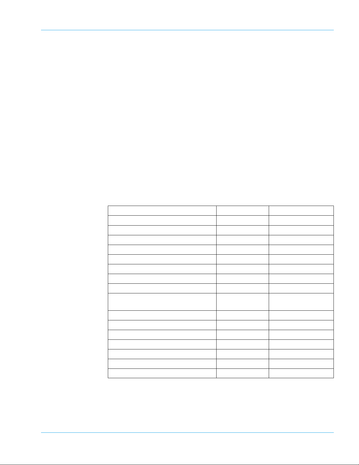
Analysis Parameters and Detection Principles
Parameter Test name Applied
Prothrombin Time PT Coagulation Method
Activated Partial Thromboplastin Time APTT Coagulation Method
Fibrinogen Fbg Coagulation Method
Thrombin Time TT Coagulation Method
Protein C coagulometric PCcl Coagulation Method
Batroxobin BXT Coagulation Method
LA1 Screening* LA1 Coagulation Method
LA2 Confirmation* LA2 Coagulation Method
Factor Assay** II, V, VII, VIII, IX,
Antithrombin III AT3 Chromogenic Method
α2-Antiplasmin* APL Chromogenic Method
Plasminogen* Plg Chromogenic Method
Protein C chromogenic BCPC Chromogenic Method
Heparin Hep Chromogenic Method
D-Dimer Plus*, Advanced D-Dimer*** DDPl, AdDD Immunoassay Method
P-FDP**** PFDP Immunoassay Method
Coagulation Method
X, XI, XII
(*) Not available in the USA.
(**) Data evaluated for factors VII and VIII only.
(***) Only available for use in the USA.
(****) Only available for use in Asia.
Revised January 2003 - 2.0_en
Sysmex CA-500 series 1-1
Page 8

Introduction
Manufacturer
SYSMEX CORPORATION
1-5-1 Wakinohama-Kaigandori
Chuo-ku, Kobe 651-0073
Japan
European Representative
SYSMEX EUROPE GmbH
Bornbarch 1
D – 22848 Norderstedt
Tel.: +49 40 5 27 26-0
Fax: Tel.: +49 40 5 27 26-100
Ordering of Supplies and Replacement Parts
If you need to order supplies or replacement parts, please contact your
local Sysmex representative.
Service and Maintenance
Training Courses
CE-Mark
Please contact the Service Department of your local Sysmex representative.
For further information please contact the Sysmex representative in your
country.
The IVD system described in this manual is marked with a CE mark
which confirms the observance of the essential requirements of the following European directives:
-98/79/EC in-Vitro Diagnostics Directive.
CA-500 series instruments with serial numbers shown below or smaller
numbers only conform to the 89/336/EEC electromagnetic compatibility.
CA-510 A1342
CA-520 A1017
CA-530 A1902
CA-540 A3883
CA-550 A1051
CA-560 A1110
1-2 Sysmex CA-500 series
Revised January 2003 - 2.0_en
Page 9
1.2 Explanation of Signs
Introduction
This manual carries a variety of illustrations to make sure that the product can be used safely and correctly, thus preventing users and others
from suffering injuries and damage to property.
The illustrations and meaning are described in the following.
Do understand what they mean before proceeding to the text of the
MANUAL.
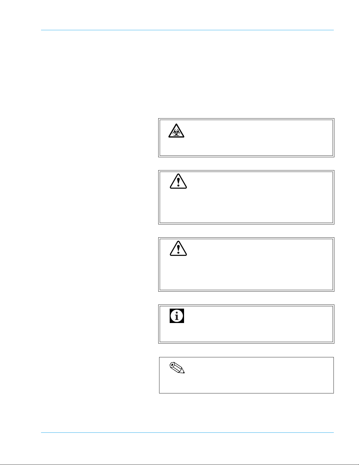
Risk of Infection
Indicates the presence of a biohazardous material or
condition.
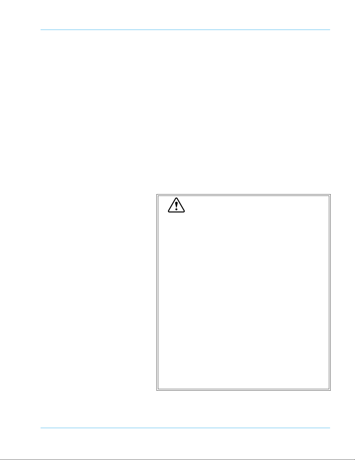
Warning
If this sign is ignored and the instrument is operated
incorrectly, there is a potentially hazardous situation
which could result in death or serious injury of operator,
or grave property damage.
Revised November 2003 - 2.0_en
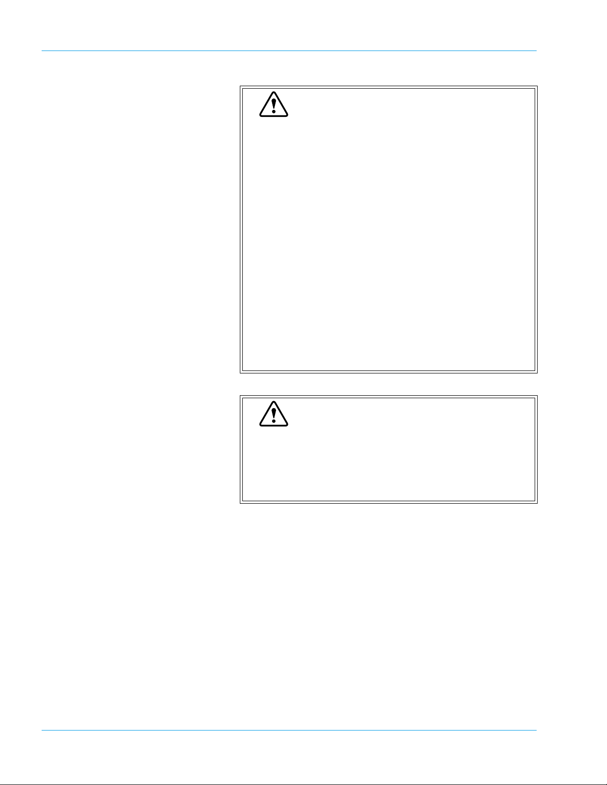
Caution
If this sign is ignored and the instrument is operated
incorrectly, there is a potentially hazardous situation
which may result in injury of operator, adverse effect on
results, or may cause property damage.
Important
Indicates what we would like you to know to maintain
instrument performance and prevent its damage.
Note
Indicates information which will come handy in operating the
instrument.
Sysmex CA-500 series 1-3
Page 10

Introduction
1.3 Names
• Sysmex is a registered trademark of SYSMEX CORPORATION in
the USA, in Germany and other countries.
• CA CLEAN I and CA CLEAN II are trademarks of SYSMEX COR-
PORATION in the USA, in Germany and other countries.
• Actin, Ci-Trol, Data-Fi and Innovin are registered trademarks of
Dade Behring Inc in the USA, in Germany and other countries.
• Dade is a registered trademark of Dade Behring Inc.
• Pathromtin and Thromborel are registered trademarks of Dade
Behring Marburg GmbH in Germany and other countries and are
trademarks of Dade Behring Marburg GmbH in the USA.
• VACUTAINER is a registered trademark of Becton, Dickinson and
Company.
• VACUETTE is a registered trademark of Greiner Bio-One GmbH.
1.4 Serial Number
1.5 Revision History
• Other trademarks referenced are property of their respective owners.
CA-500 series instruments with serial numbers below or smaller
CA-510 A1300
CA-520 A1018
CA-530 A1805
CA-540 A3405
will not have the capability to manage more than 7 Assays/Standard
curves and they are limited to use 7 × 6 QC files.
Version Date Changes
Manual Software
1.0 00-13 October 2001 Launch Version
2.0 00-15 January 2003 Second Edition
2.0 00-15 May 2003 Minor Correction
2.0 00-15 September 2003 Minor Correction
2.0 00-15 November 2003 To conform with IVD
Directive
2.0 00-17 April 2004 Minor Correction
1-4 Sysmex CA-500 series
Revised April 2004 - 2.0_en
Page 11

2. Safety Information ...................................................2-1
2.1 Specified Conditions of Use ........................................................2-1
2.2 General Information ....................................................................2-1
2.3 Installation Location ..................... ... ... .... .....................................2-3
2.4 Avoidance of Infections ...............................................................2-3
2.5 Handling of Reagents ............................. ... ... ... ... .... .....................2-4
2.6 Maintenance of the Instrument ....................................................2-5
2.7 Disposal of Materials ...................................................................2-5
2.8 Markings on the Instrument .........................................................2-6
2.9 Personnel .................................. .................................................. 2-8
2.10 Storage Condition (Transportation) .. ... .... ... ... ... ... .... ... ... ....... ... ... ..2-8
Revised November 2003 - 2.0_en
Sysmex CA-500 series
Page 12
2. Safety Information
Before operating this instrument, carefully read this manual, and strictly
follow the instructions given in them.
2.1 Specified Conditions of Use
The instrument shall only be used for in vitro analysis of human blood or
artificial control blood. It may not be used for any other purpose.
Only reagents and cleaning solutions mentioned in this manual are permitted for use.
By observing the specified conditions of use, the frequency of cleaning
and maintenance work can be reduced.
2.2 General Information
Safety Information
Warning
• Keep long hair, fingers and clothing away from rotating parts of the instrument.
• During analysis, do not open the light shield cover
and put in hands or fingers.
This could cause injury. When the light shield cover
is opened during analysis, the alarm sounds and the
operation stops.
• In the event that the instrument emits an abnormal
odor or any smoke, turn off its power supply immediately and pull out the power plug from the wall
socket.
If the instrument is used continuously in that state,
there is a hazard that fire, electrical shock, or injury
may result. Contact your local service representative
for inspection.
• Take care not to spill blood or reagent, or drop wire
staples or paper clips into the instrument.
These might cause short circuit or smoke emission. If
such problem should occur, turn off the power supply
immediately and pull out the power plug from the wall
socket. Then contact your local service representative for inspection.
Revised January 2003 - 2.0_en
Sysmex CA-500 series 2-1
Page 13
Safety Information
Warning
• Do not touch the electric circuits inside the instrument. Especially with wet hands there is a risk of
electric shock.
• Never put the power plug in any socket other than
that specified. When installing the instrument, be
sure to ground it. Otherwise, fire or electrical shock
will result.
• Take care not to damage the power cord, put a
heavy thing on it, or pull it forcibly. Otherwise, the
wire may become shorted or break, causing fire or
electrical shock.
• When connecting the instrument to a peripheral (host
computer, etc.), be sure to switch off the power supply beforehand. Otherwise, fire or electrical shock
may result.
• Use the check-digit as much as possible. If the
check-digit cannot be used, the potential of the incorrect reading of the barcode label may be increased.
Caution
• Read this manual carefully to operate the instrument
by the proper method. Keep it securely in a specified
location for future reference.
• This instrument must only be operated as instructed
in this manual.
2-2 Sysmex CA-500 series
Revised January 2003 - 2.0_en
Page 14
2.3 Installation Location
Safety Information
Caution
• Install in a place which is not subject to water splash.
• Install in a place which is not subject to adverse
effects of high temperature, high humidity, dust,
direct sunlight, etc.
• Do not give the instrument a strong vibration or
impact.
• Install at a place which is well ventilated.
• Do not install near devices that cause signal noise,
such as radios and centrifugal machines.
• Do not install near chemicals storage or in a place
where gas is generated.
2.4 Avoidance of Infections
Risk of Infection
• In principle, all parts and surfaces of the instrument
must be regarded as infective.
• Never touch waste, or parts having been in contact
with waste, with bare hands.
• Should you inadvertently come in contact with potentially infective materials or surfaces, immediately
rinse skin thoroughly with plenty of water, then follow
the antiseptic regulations of your laboratory.
• Be careful when handling samples. Always wear
latex or non latex examination gloves; otherwise contamination could result. If a sample happens to enter
your eye or a cut, wash it off with plenty of water, and
immediately visit a physician.
• Control plasma may also be infective. Wear latex or
non latex examination gloves during QC process. If
plasma happens to enter your eye or a cut, wash it
off with plenty of water, and immediately visit a physician.
• Use care when handling waste liquid. If it adheres to
the skin or clothing, wash it off using an antiseptic
solution.
Revised November 2003 - 2.0_en
Sysmex CA-500 series 2-3
Page 15
Safety Information
2.5 Handling of Reagents
Warning
• Avoid direct contact with reagents. Reagents can
cause irritation of the eyes, skin and mucous membranes.
• If a reagent happens to adhere to the hand or the
skin of another area, wash it off immediately using
plenty of water.
• If a reagent happens to enter your eye, wash it off
immediately using plenty of water, and take medical
treatment at once.
• If you should swallow it inadvertently, call for a physician immediately, drink a large volume of water, and
then induce vomiting.
• CA CLEAN I is a strong alkaline cleaning material. It
should not come in contact with skin or clothing. If it
happens nevertheless, rinse skin or clothing with
plenty of water to avoid injury or damage.
Caution
• Read the instructions described on the reagent containers.
• After unpacking, be sure not to allow dust, dirt, or
bacteria into the reagents.
• Do not use reagents that have passed the expiration
period.
• Handle a reagent gently to prevent formation of bubbles. Shake carefully if necessary.
Do not use directly after transportation.
• Take care not to spill a reagent. If it has spilled, wipe
it off immediately using a wet cloth or something.
• Prepare a sufficient volume of reagent which takes
into consideration the minimum sample volume
required. When the volume of the reagent is insufficient, sample may not be analyzed accurately.
• The CA CLEAN I rinse solution contains sodium
hypochlorite. If the material makes contact with the
instrument's surfaces, it will affect the surface finish.
There is a danger of corrosion. Immediately wipe up
CA CLEAN I with a damp cloth.
• A reagent is a chemical substance employed for
external diagnosis and cannot be used for any medical treatment.
Revised January 2003 - 2.0_en
2-4 Sysmex CA-500 series
Page 16
2.6 Maintenance of the Instrument
Always wear latex or non latex examination gloves when
performing maintenance work or inspection. Also use the
specified tools and parts. After work is over, wash the
hands in an antiseptic solution. There is a possibility that
those areas of the hand which came in contact with
blood could suffer infection.
When carrying out inspection and maintenance of the
instrument, use only the specified tools and parts. Never
use substitute parts or modify parts. Such actions are
dangerous and prohibited by the Pharmaceutical Affairs
Law.
Safety Information
Risk of Infection
Warning
2.7 Disposal of Materials
Risk of Infection
When discarding waste liquid, instrument consumables
and instrument, take proper steps to dispose of them as
medical, infective and industrial wastes.
If they are contaminated with blood, there is a possibility
of bacterial infection occurring.
Revised November 2003 - 2.0_en
Sysmex CA-500 series 2-5
Page 17
Safety Information
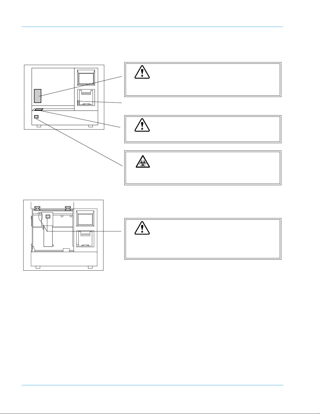
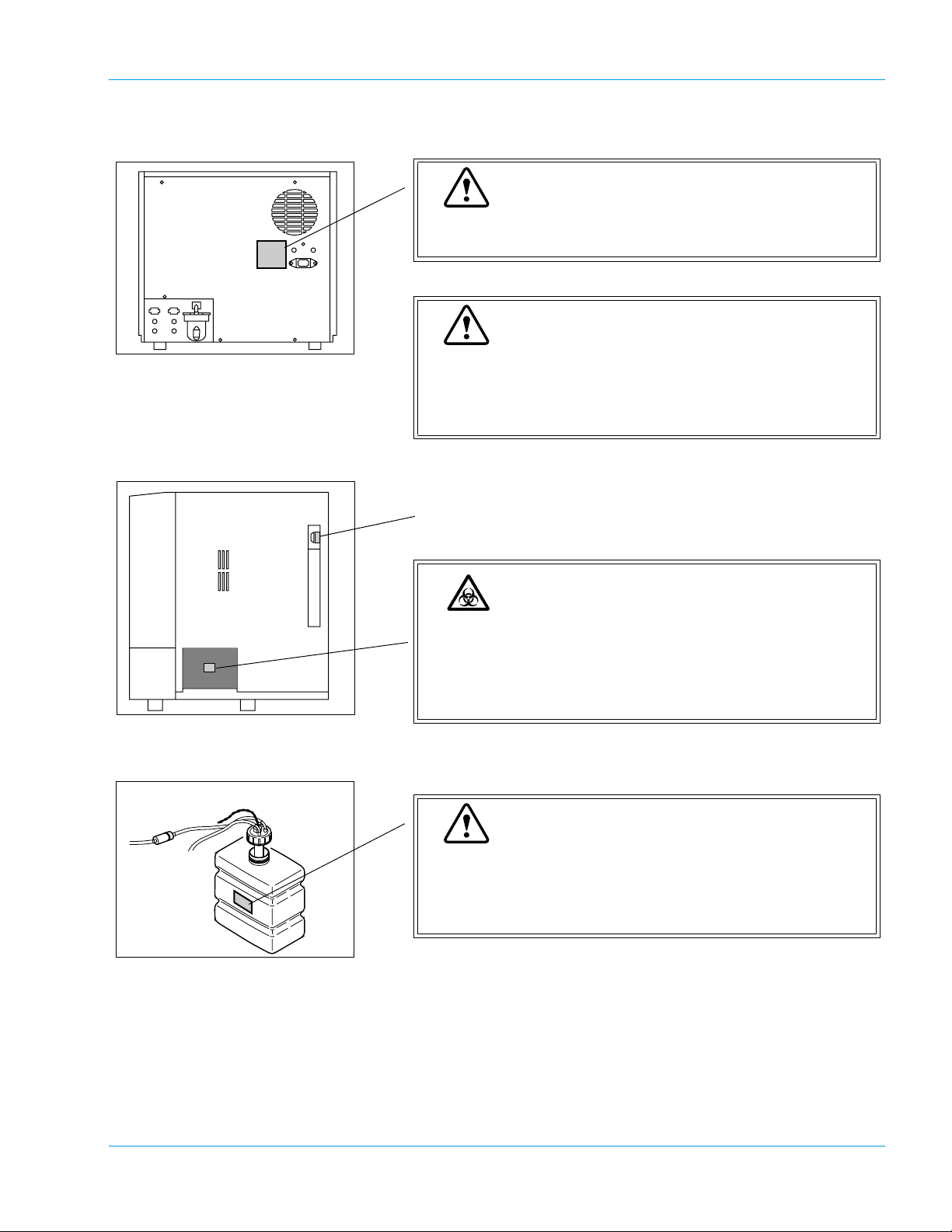
2.8 Markings on the Instrument
Warning
DO NOT place your fingers and hands inside while analyzing. Pipette can move in any direction.
Fast Stop (Mechanical Stop)
Warning
DO NOT press on the sampler unit to prevent damage.
Risk of Infection
In principle, all parts and surfaces of the instrument must
be regarded as infective.
Warning
When the arm is to be moved while the pipette is in the
down position, pull up the pipette to the same height as
catcher, and move the arm.
Revised November 2003 - 2.0_en
2-6 Sysmex CA-500 series
Page 18
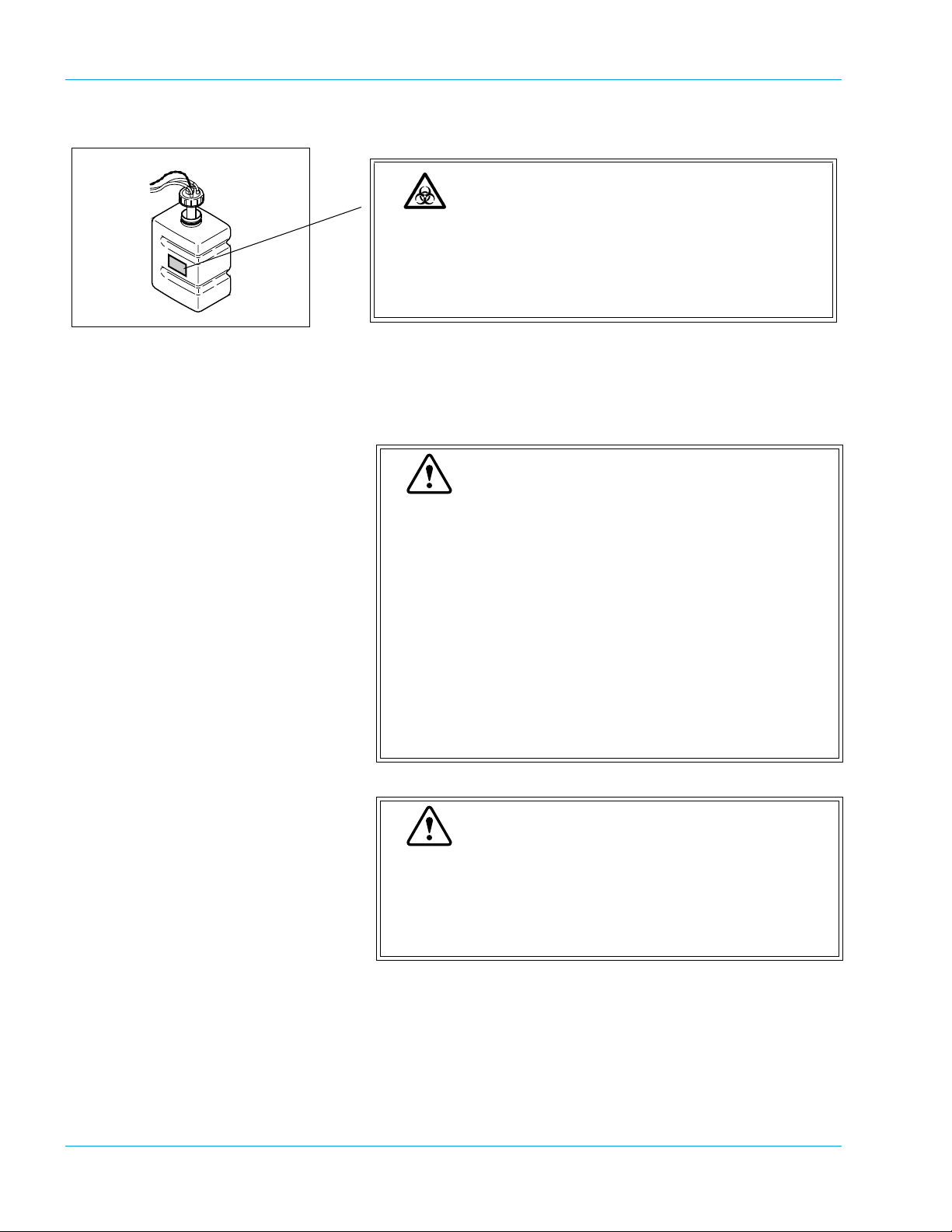
Safety Information
Warning
To avoid risk of electrical shock, disconnect the power
cord before replacing the fuse.
Warning
Proper use of the appropriate power cord assures adequate grounding for the system. Failure to properly
ground the instrument bypasses important safety features and may result in an electrical hazard.
RS-232C Serial Port (HC Connector)
Risk of Infection
To avoid contact with biohazardous materials, gloves
must be worn when handling the tube trash and used
reaction tubes.
Wash your hands with an antimicrobial solution after
completing the procedure.
Warning
To avoid dusts or contaminants entering the rinse bottle,
ensure the float switch does not touch any surfaces
when replenishing distilled water. Dusts or contaminants
will cause malfunction of the solenoid value.
Revised April 2004 - 2.0_en
Sysmex CA-500 series 2-7
Page 19
Safety Information
2.9 Personnel
Risk of Infection
The waste container and contents should be considered
potentially biohazardous. Do not handle the waste container without proper protective equipment. Wear gloves
when handling. Wash your hands with an antiseptic solution after completing the procedure.
Caution
• Those who have no or only limited experience in
using the instrument are recommended to have guidance or assistance from those with sufficient experience.
• If the instrument has developed a problem by any
chance, a person in charge of it should take steps
within the range specified in Instructions For Use. As
to problems other than those mentioned, contact
your local service representative for repair.
• Instrument unpacking, installation, and confirmation
of initial operation must be done by your local service
representative.
Warning
This instrument is clinical laboratory equipment for
screening.
When making clinical judgment based on analysis
results, the doctor must also consider clinical conditions
and other inspection results for an overall judgment.
2.10 Storage Condition (Transportation)
• Ambient Temperature: -10ºC to +60ºC
• Relative humidity: 95% or less
(Non condensing / Keep dry)
2-8 Sysmex CA-500 series
Revised November 2003 - 2.0_en
Page 20

3. Design and Function ...............................................3-1
3.1 Overview ..................................................................................... 3-1
3.2 Operation Flow ....................................................... .....................3-8
Revised January 2003 - 2.0_en
Sysmex CA-500 series
Page 21
3. Design and Function
3.1 Overview
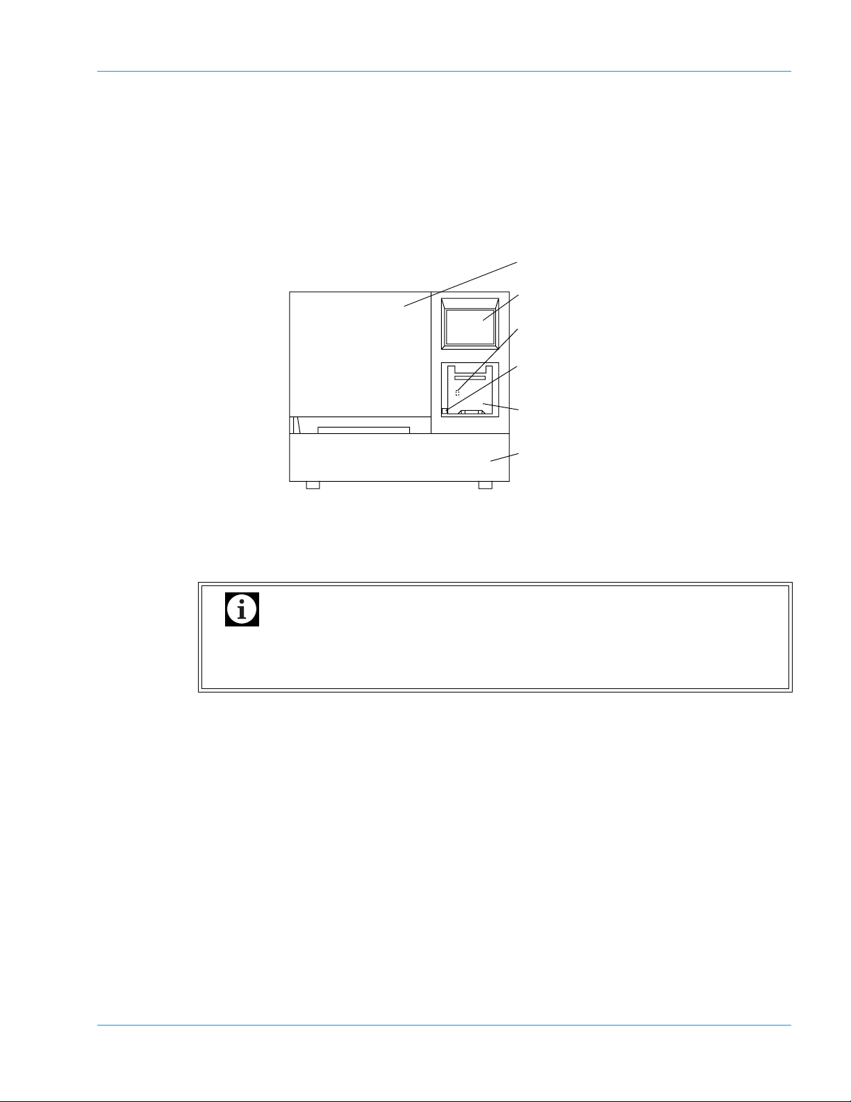
Front
Design and Function
1. Light Shield Cover
2. LCD (Liquid Crystal Display)
3. LCD Contrast Adjustment Knob
4. Mechanical Stop Switch
5. Built-in Printer
6. Sampler
1. Light Shield Cover
Prevents photoelectric detection from being affected by scattered light from external sources.
Ensure this cover is shut before proceeding to analyze any samples. Analysis cannot be started
if this cover remains open.
Important
Do not open the Light Shield Cover while analysing. Opening the cover will suspend analysis and beep the alarm. Also, opening the cover and inserting your hand
may cause injury.
2. Liquid Crystal Display (LCD)
Displays analysis results, reaction curves, sample numbers, test conditions, etc.
The LCD functions as a touch-sensitive control panel. The operator can execute various opera-
tions and enter settings by lightly touching keys displayed on the LCD.
3. LCD Contrast Adjustment Knob
Controls LCD contrast. This knob is located inside the printer cover.
Revised January 2003 - 2.0_en
Sysmex CA-500 series 3-1
Page 22
Design and Function
4. Mechanical Stop Switch
Used to immediately stop the mechanical unit in the instrument in the event of an emergency.
Note that the power of the instrument is not turned off even when this switch is turned on. If
emergency stop of the instrument is required due to power failure of the laboratory, immediately turn off the power of the instrument.
If there is a sample that has been already dispensed, this sample has to be reanalyzed from the start.
5. Built-in Printer
Setting conditions, error messages and analysis results are printed out on the thermal paper of
the graphic printer. The LCD contrast adjustment knob is located inside the built-in printer.
6. Sampler
The sampler has a load capacity of one sampler rack with 10 sample tubes. The sampler racks
are specific for Sysmex instruments. One rack can be set on the sampler at a time.
Pull out the Sampler toward you to load a rack. Once the rack is loaded, the sampler will oper-
ate without the need for intervention by the operator.
Important
Note
• The sampler unit is locked while sampling and dispensing. Once the status has become
ready to set samples, the sampler lock is released. You can pull out the sampler to set
samples on available positions on the rack in use, or to place a next rack to allow continuous analyses.
• The sampler unit can also be pulled out by the STAT sample analysis procedure to
allow an analysis of a STAT sample.
3-2 Sysmex CA-500 series
Revised January 2003 - 2.0_en
Page 23
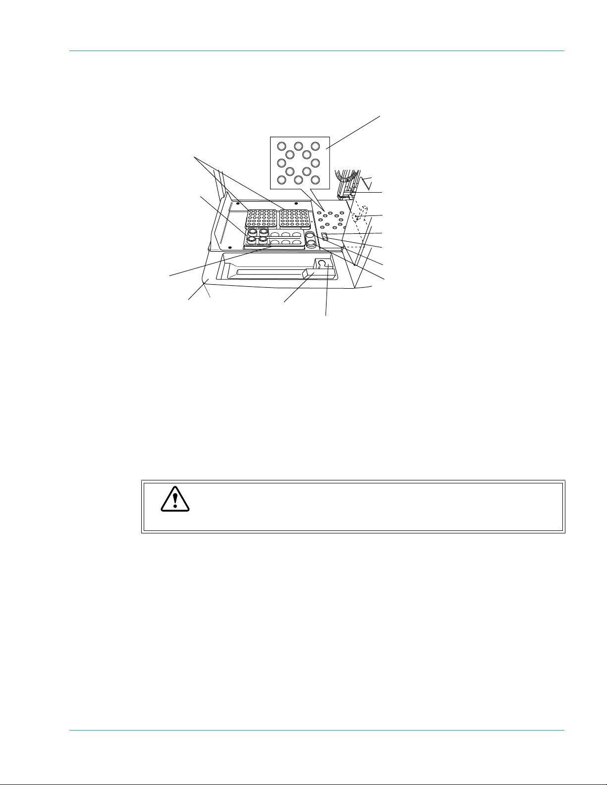
Front Interior (When Opening Light Shield Cover)
888
10
10 10
8
10
97
88
1. Reaction Tube Rack
2. Reagent Cooler Holder
3. Reagent Rack
Design and Function
7. Detection Well (For Immunology
Method)
8. Sample Incubation Wells
9. Detection Well (For Chromogenic
Method)
10. Detection Well (For Coagulation
Method)
11. Probe
12. Reaction Tube Trash
13. Probe Rinse Cup (Outside)
14. Probe Rinse Cup (Inside)
15. CA CLEAN I Holder (default)
16. Buffer Holder (default)
4. Sampler
5. ID Barcode Reader
6. STAT Sample Rack
1. Reaction Tube Rack
Two reaction tube racks can be set. One rack holds up to 30 reaction tubes (SU-40). Tube posi-
tion numbers are assigned from the right rear position of the right rack (No. 1) and count
upwards moving toward the front.
2. Reagent Cooler Holders (For CA-530, CA-540, CA-550 and CA-560 only)
Can hold up to 4 vials with cooler function.
3. Reagent Rack
Reagent vials, whose outer diameter is 22 mm and he ight is 40 mm , can be set directly. Use
sample cups or optional holders to place any vial with other outer diameters.
Caution
If any vial higher than 40 mm is used, the Probe will be damaged permanently.
4. Sampler
Can hold one sample rack.
5. ID Barcode Reader (Optional on CA-510, CA-530 and CA-550)
ID Barcode Reader moves in front of the rack and reads the barcoded label automatically.
6. STAT Sample Rack
Place a STAT sample collection tube or sample cup here. If a sample collection tube is placed,
use optional holders to make the tube diameter fit the rack.
7. Detection well (For Immunology Method: CA-550 and CA-560 only)
Detection well for the immunologic sample. The number of wells is one. The detector is always
kept at 37.0ºC ± 1.0ºC.
Revised September 2003 - 2.0_en
Sysmex CA-500 series 3-3
Page 24
Design and Function
8. Sample Incubation Wells
Six incubation wells are provided, and these wells are kept at 37.0ºC ± 1.0ºC.
9. Detection Well (For Chromogenic Method: CA-530, CA-540, CA-550 and CA-560 only)
Detection well for the chromogenic sample. The number of wells is one. The detector is always
kept at 37.0ºC ± 1.0ºC.
10. Detection Wells (For Coagulation Method)
Four scattered light detection wells are provided, and these wells are kept at 37.0ºC ± 1.0ºC.
11. Probe
This pipette is used to aspirate samples and reagents. It is kept at 37.0ºC ± 1.0ºC.
12. Reaction Tube Trash
Used reaction tubes are disposed into this trash.
13. Probe Rinse Cup (Outside)
The outside of the probe is rinsed with the rinse fluid kept in this rinse cup.
14. Probe Rinse Cup (Inside)
The inside of the probe is rinsed in this rinse cup.
15. CA CLEAN I Holder
CA CLEAN I detergent is set in the vial, whose outer diameter is 22 mm or less, and height is
50 mm or less.
Caution
Use the provided vials to hold the CA CLEAN I detergent. If any vial higher than
50 mm is used, the Probe will be damaged permanently.
16. Buffer Holder
Buffer diluent used for sample dilution is set in the vial, whose outer diameter is 22 mm or less,
and height is 50 mm or less.
Caution
Use the provided vials for the container to keep the Buffer. If any vial higher than
50 mm is used, the Probe will be damaged permanently.
3-4 Sysmex CA-500 series
Revised April 2004 - 2.0_en
Page 25
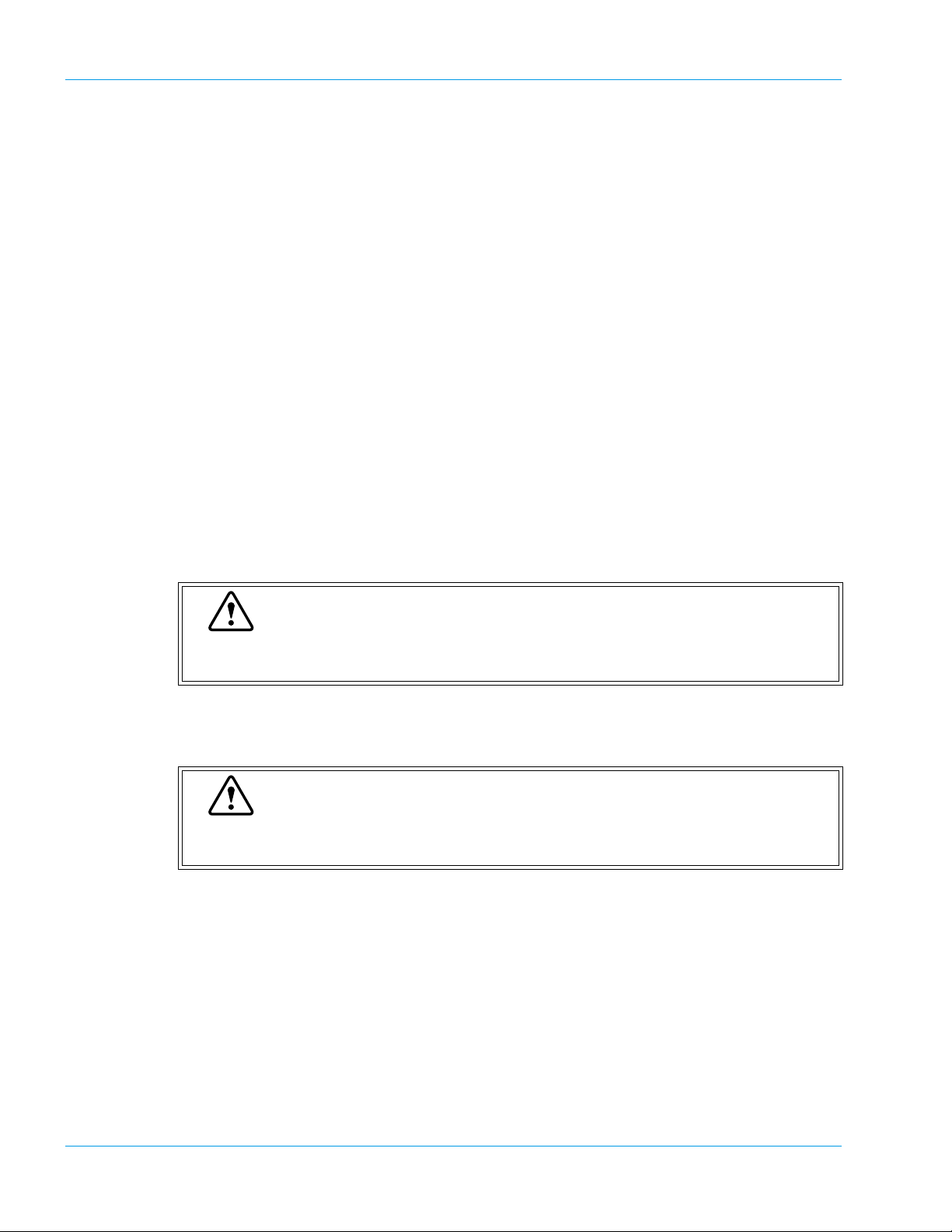
Left Side
Design and Function
2. Cover Sensor Switch
1. Power Switch
3. Cooler Unit
1. Power Switch
Turns the power ON or OFF.
Caution
Please allow at least 5 seconds between turning the instrument OFF and back ON,
or the fuse may be blown.
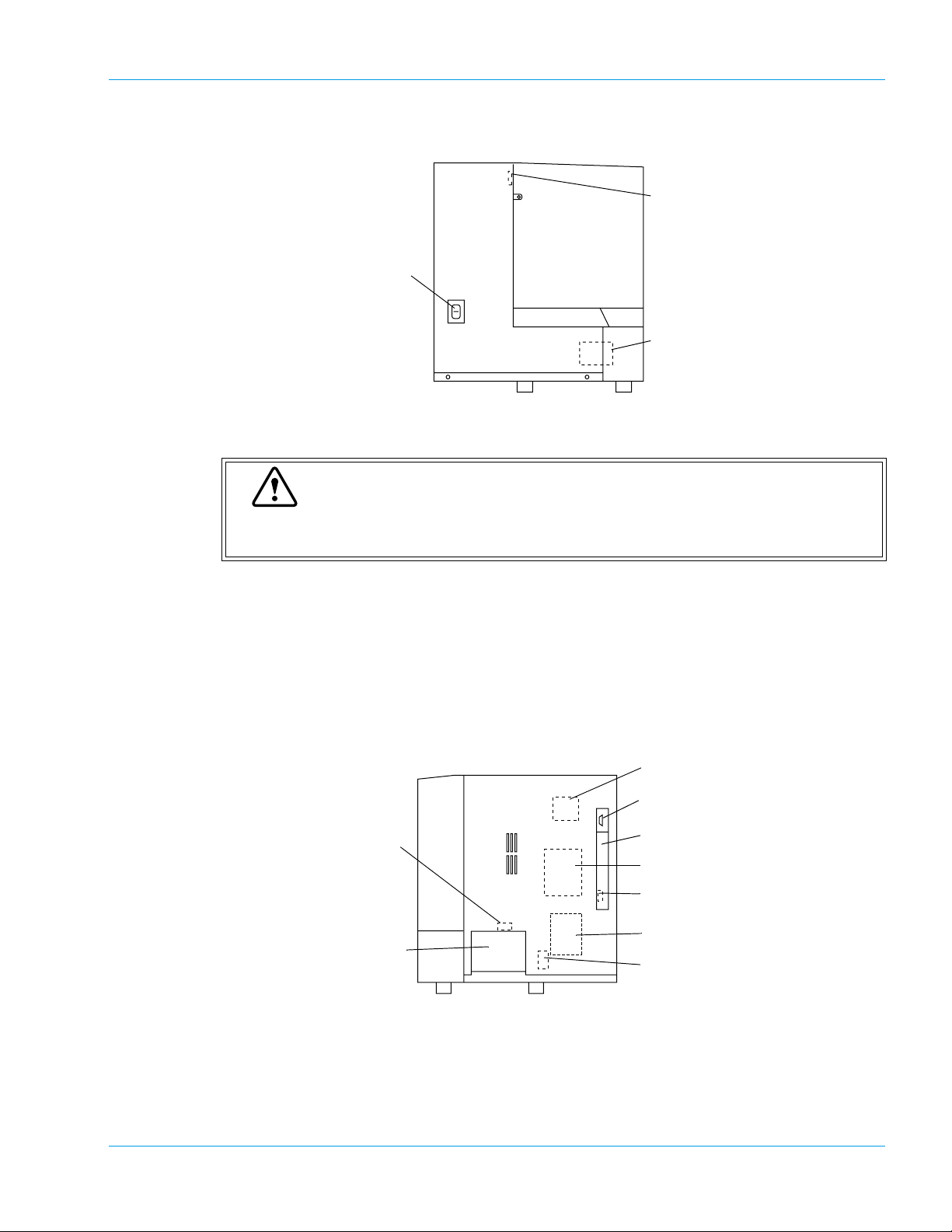
Right Side
2. Cover Sensor Switch
This monitors if the Light Shield Cover is closed.
3. Cooler Unit
This keeps the reagent cool.
8. Solenoid Valve
for Sample Aspiration
9. Reaction Tube Trash
Drawer
1. X-Y Drive Motor
This motor drives the Probe unit in the X-axis and Y-axis directions.
1. X-Y Drive Motor
2. Host Computer Serial Port
3. Memory Card Cover
4. Pressure Pump
5. DIP Switch
6. Vacuum Pump
7. Solenoid Valve
for Probe Rinse
2. Host Computer Serial Port
For connecting to an external host computer.
Revised January 2003 - 2.0_en
Sysmex CA-500 series 3-5
Page 26
Design and Function
3. Memory Card Cover
This card has PROM chips to load the CA-500 program in to RAM memory. (In tended for your
local service representative use only)
4. Pressure Pump
Supplies the pressure. The instrument cannot function properly at lower pressures.
5. DIP Switch
Changes the system settings.
(Intended for your local service representative use only)
6. Vacuum Pump
Supplies vacuum. The instrument cannot function properly if the vacuum level is lower.
7. Solenoid Valve for Probe Rinse
This valve controls the supply of the rinse solution to the rinse cup unit.
8. Solenoid Valve for Sample Aspiration
This valve controls the aspiration of sample plasma with high accuracy.
9. Reaction Tube Trash Drawer
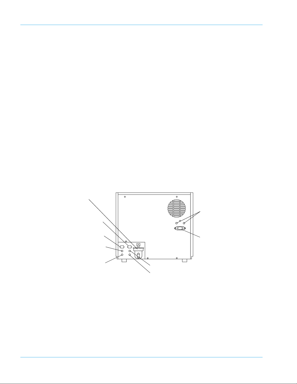
Rear
Used for storing used reaction tubes.
1. Trap Chamber
6. Fuse Holder
2. Float Switch Connector
for Waste Bottle
3. Float Switch Connector
for Rinse Bottle
4. Pressure Supply Nipple
for Rinse Bottle
5. Rinse Aspiration Nipple
8. Vacuum Nipple for Waste Bottle
9. Waste Outlet Nipple
7. Power Connector
1. Trap Chamber
Prevents the waste fluid from flowing back to affect the vacuum pump, in the event of an
abnormality with the instrument.
2. Float Sensor Connector for Waste Bottle (“WASTE”)
For connecting the float sensor switch, located on the waste container, for detecting the waste
fluid level.
3-6 Sysmex CA-500 series
Revised January 2003 - 2.0_en
Page 27
Design and Function
3. Float Sensor Connector for Rinse Bottle (“RINSE”)
For connecting the float sensor switch, located on the rinse container, for detecting rinse water
level.
4. Pressure Supply Nipple for Rinse Bottle (Colored Black)
To be connected via a tube with the Rinse Bottle.
Important
When the Rinse Bottle is to be opened, disconnect this tubing first to release the
pressure accumulated inside the Rinse Bottle. Failing to do this will splash the pressurized rinse fluid.
5. Rinse Aspiration Nipple (Colored Blue)
For aspirating the rinse water from the Rinse Bottle. To be connected via a tube to the Rinse
Bottle.
Important
When the Rinse Bottle is to be opened, disc onnecting this tubing first will splash the
pressurized rinse fluid. Disconnect the black tubing first.
6. Fuse Holder
Two time-lag type fuses are installed in this Fuse Holder. Replace with the correct type of fuse
(supplied). The rating will be different depending on the instrument specification as below.
Specification Part No. Description Fuse Type Location
117 VAC 266-5106-0 Fuse 250V 6.3A ST4-6.3A-N1
Time Lag Rear Panel
(N.Amer)
220-240 VAC 266-5293-0 Fuse 250V 3.15A No. 19195
(Europe)
Time Lag Rear Panel
Warning
• To avoid risk of electrical shock, disconnect the power cord before replacing the
fuses.
• For continued protection against risk of fire, replace only with a fuse of the specified type and current ratings.
7. Power Connector
For connecting the main power supply (via the supplied power cable).
8. Vacuum Nipple for Waste Bottle (Colored Green)
To be connected via a tube with the Trap Chamber.
9. Waste Outlet Nipple (Colored Red)
For draining waste fluids. Must be connected via a tube to the Waste Bottle.
Revised January 2003 - 2.0_en
Sysmex CA-500 series 3-7
Page 28
Design and Function
3.2 Operation Flow
Manual Order Registration On-Line Order Registration
(Manual Inquiry)
Inspection Before Turning On Power
Turn On Power
• Self Check
Ready
Prepare Reagents
Register Analysis
(Manual Registration)
Prepare Samples
Operation After Completion of Analysis
: Indicates actions performed by the operator.
Prepare Samples
Register Analysis
Press [HC] key
Press [Start] key
• Execution of Analysis
• Completion of Analysis
Ready
Turn Off Power
On-Line Order Registration
(Auto Inquiry)
Prepare Samples
: The message "Ready" will appear on the LCD screen, indicating that analysis, setting, dat a
processing and other operations can be executed.
Revised January 2003 - 2.0_en
3-8 Sysmex CA-500 series
Page 29

4. Installation Environment .........................................4-1
4.1 Installation and Relocation ........................ ... ... ... .... ... ... ... .... ... ... ..4-1
4.2 Installation Location ..................... ... ... .... ... ... ... ... .... ... ... ... .... ........4-1
4.3 Basic Instrument Settings ...................... ... ... ... ... .... ... ... ... .... ... .....4-3
Revised January 2003 - 2.0_en
Sysmex CA-500 series
Page 30
4. Installation Environment
4.1 Installation and Relocation
Installation of the instrument must be conducted by your local service
representative. If it is necessary to relocate the instrument, contact your
local service representative.
It is to be noted that if problems should develop as a result of relocation
conducted by a customer, it will void the warranty even if the instrument
is in the warranty period.
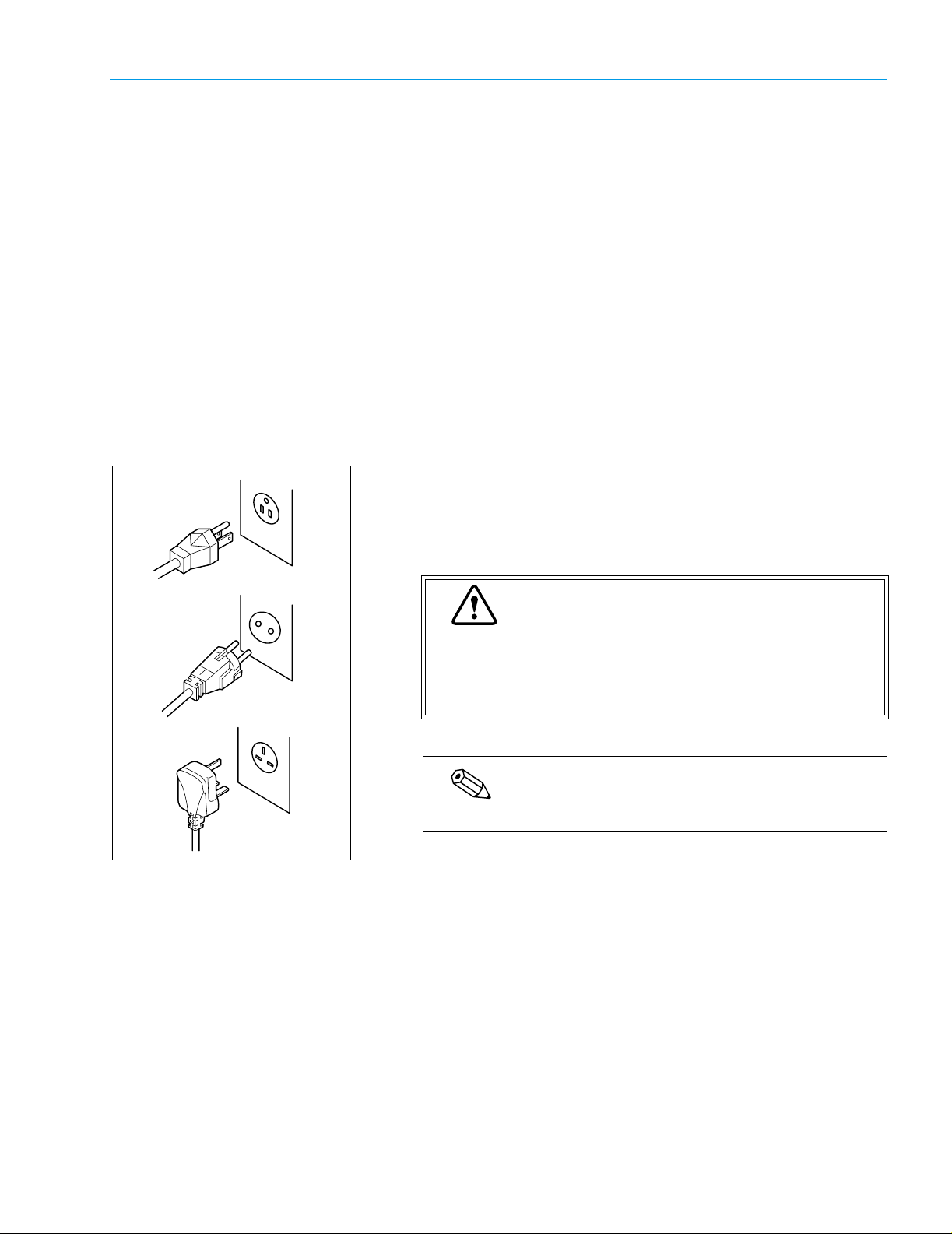
4.2 Installation Location
Grounding
The power cord of each instrument uses the 3P plug. When the power
supply socket is 3P (with ground) type, simply plug it to the socket. The
type of cord and plug supplied depends on the source voltage for the system.
Installation Environment
Installation Space
Warning
Proper use of the appropriate power cord assures adequate grounding for the system. Failure to properly
ground the instrument bypasses important safety features and may result in an electric hazard.
Note
The number of power supply sockets required is one.
To ensure optional instrument performance properly, install it at an
appropriate location.
• Select a place where the power supply is located close.
• Be sure to use the supplied bottles to collect rinse solution and waste.
• Keep a space for maintenance and service. Giving consideration to
heat radiation by the instrument, provide at least 50 cm distance from
the wall to sides, rear, and top panels.
Revised January 2003 - 2.0_en
Sysmex CA-500 series 4-1
Page 31

Installation Environment
The dimensions of the instrument are shown below. The power cord is
1.8 m long.
Width (mm) Depth (mm) Height (mm) Weight (kg)
Main unit 540 470 487 Approx. 45
487
540
470
Caution
Be sure to place the rinse bottle and waste bottle on the
base on which the instrument is set. Do not place them
on the instrument. They may cause the instrument to
break down or to fail to produce correct results.
4-2 Sysmex CA-500 series
Revised January 2003 - 2.0_en
Page 32

Installation Environment
• Use the instrument at an ambient temperature of 15 - 35ºC.
• Use it at a relative humidity range of 30 - 85%.
• When the ambient temperature and humidity are not appropriate,
• Avoid using the instrument in a place where the temperature can
• Avoid using the instrument in a place where it may be frozen.
• Avoid using the instrument where it can be exposed to direct sun-
• Select a well-ventilated place.
• Avoid using it at a place close to a wireless telegraph, communica-
4.3 Basic Instrument Settings
Installation Environment
control by air conditioning.
become extremely high or low.
light.
tion equipment, etc. which may emit high-frequency waves or interfere with radio waves.
Contrast Adjustment for LCD Screen
Remove the printer cover, and adjust LCD screen contrast (shade) using
the contrast adjust dial on the left side of the printer.
Dark
Light
Turning up the dial makes the screen darker and turning down makes it
lighter.
Setup of System (Date/Time)
Set date and time.
The instrument has a built-in clock, so there is no need to set the date and
time every day. Should the power be turned off, the built-in clock is powered by an internal battery.
1. Press [Special Menu] key on the Root Menu screen.
2. Press [Settings] key on the Root Menu screen.
The contents of the Root Menu will change over.
The Setting Menu screen will appear.
Revised January 2003 - 2.0_en
Sysmex CA-500 series 4-3
Page 33

Installation Environment
Ready
Sysmex
Settings
General Set Up
Date/Time
Date 12/01/2001
Time 16:35:38
Replace Rack? YES!
Auto Val/Out
Data Check
Analysis Settings
I/O Setting
General Set Up
Ready
Sysmex
Replace Rack? YES!
Date/Time
Date Format
Password Setting
Ready
Sysmex
Replace Rack? YES!
HC IP
Print Settings
HC IP
HC IP
7
4
1
0
C
Main
Menu
Return
Date
89
5
6
3
2
/
Enter
Quit
3. Press [General Set Up] key on the Setting Menu screen.
The General Set Up Menu screen will appear.
4. Press [Date/Time] key on the General Set Up Menu screen.
The Date/Time Setting screen will display current date and time.
5. Using [↑] and [↓] keys, move the cursor to select Date or Time.
6. Using the numeric keys, set Date and Time, and press [Enter] key.
The parameter in the cursor position is set and the cursor will move
to the next parameter.
Important
• When entry is made in the wrong format, the setting
is not executed.
• If the number of day or month is a single digit, enter it
with a 0 preceding it.
• Enter the time in a 24-hour clock system.
7. When setting is completed, press [Quit] key.
The Renew Confirmation screen will appear.
Sysmex
Replace Rack? YES!
HC IPReady
8. Press [FIX] key, [Continue] key, or [Cancel] key.
[FIX] key: Changes to the renewed setting and returns to the
General Set Up Menu screen.
RENEW SETTING ?
[Continue] key: Returns to the Date/Time Setting screen and allows
continued operation.
[Cancel] key: Cancels the renewed setting and returns to the Gen-
ContinueCancel FIX
4-4 Sysmex CA-500 series
eral Set Up Menu screen.
Revised January 2003 - 2.0_en
Page 34

5. Operation ..................................................................5-1
5.1 Display Screens and Operation Keys .........................................5-1
5.2 Menu Tree ...................................................................................5-3
5.3 Types of Alarm ............................................................................5-5
5.4 Inspection before Turning ON the Power ....................................5-5
5.5 Turn ON the Power .....................................................................5-7
5.6 Prepare Reagents .......................................................................5-8
5.7 Set Reaction Tubes ...................................................................5-13
5.8 Confirm Standard Curve ...........................................................5-14
5.9 Execute Quality Control ............................................................5-15
5.10 Prepare Samples ......................................................................5-15
5.11 Set Sample Nos. .......................................................................5-19
5.12 Manual Inquiry ................................. ... .... ... ... ... ... .... ... ... ... .... ... ...5-22
5.13 Automatic Inquiry ......................................................................5-22
5.14 Start Analysis ............................................................................5-24
5.15 Automatic Sensitivity Adjustment of the Detector
(for CA-530, CA-540, CA-550 and CA-560 only) ......................5-26
5.16 Display Analysis Result .............................................................5-27
5.17 Interrupt Analysis ......................................................................5-28
5.18 Add Samples ... ... ... ... .... ... ... ... .... ... ... ..........................................5-29
5.19 Analyze STAT Sample ..............................................................5-30
5.20 Emergency Stop ................................. .... ... ... ... ... .... ... ... ... .... ... ...5-31
5.21 Shutdown .................................................................................. 5-33
Revised January 2003 - 2.0_en
Sysmex CA-500 series
Page 35

5. Operation
5.1 Display Screens and Operation Keys
The instrument displays all information including the instrument status,
analysis results, etc. on the LCD screen. The LCD screen is divided into
system status area, data processing area, and menu processing area. Press
a key pad, and the function indicated on the key will work.
Operation
System Status Area
(1) (2)
Ready
Sysmex
Stored
Data
Replace Rack? YES!
QC
Main Menu
1 PT 2 APTT 3 Fbg
Rack ID No.
01-01
01-02
01-03
01-04
01-05
(3)
4 TT 5 AT3
12345
Repeat
Standaed
Curve
(4)
HC IP
Group 1
ID No.
Entry
Test
Group
(5)
(6)
Start
Prev
Next
HC
Special
Menu
System Status
Data Processing
Menu Processing
The System Status Area displays [Sysmex] key, error message, analysis
status, and the status of externally connected instruments.
1. [Sysmex] key
Press this key to display Sysmex menu showing Error List, Temperature, and Paper Feed. When the instrument develops an error, causing
the alarm to sound, [ALARM RESET] key appears. Press [Error
List] key to display Error History. Press [Temperature] key to display temperatures of various units. Press [P. FEED] key to feed
printer paper.
For Sysmex Menu, refer to “12. Troubleshooting”.
2. Analysis Status
This indicates analysis status with the current instrument. “Ready”,
“Analyzing”, “Waiting” will appear.
3. Rack Replacement
This indicates whether the sample rack can be replaced or not.
4. HC (Host Computer)
The host computer is set to “Connected”. “HC” appears when sample
data for automatic output becomes available.
5. IP (Internal Printer)
“IP” appears when sample data for automatic output to the internal
printer becomes available.
Revised January 2003 - 2.0_en
Sysmex CA-500 series 5-1
Page 36

Operation
Data Processing Area
Menu Processing Area
6. [Start]/[INTERR] key
Press this key to start/stop the sampler analysis.
For STAT sample analysis, [Start STAT] key appears.
The data processing area displays analysis progress status, work list,
stored data list, reaction curve, quality control data, standard curve data,
instrument setup status, etc.
When the power supply is turned on, the work list screen (Root Menu
screen) appears.
The menu processing area always displays the menu for function selection.
In selecting a menu, touch a key that shows a menu you want to see.
After power supply turn-on, when system check is completed, the Root
Menu appears. The Root Menu is the basic menu for selecting functions
of this instrument.
5-2 Sysmex CA-500 series
Revised January 2003 - 2.0_en
Page 37

5.2 Menu Tree
Root Menu 5.5 ↑ 5.11
↓ 5.11
Repeat 5.11
ID No. Entry 5.11
HC 5.12
Stored Data 6.1 ← Top 6.2
QC 8.5 Settings 8.3
Operation
→ Bottom 6.2
↑ Search 6.2
↓ ID No./seq 6.3
Mark Select Display 6.4
Graph Delete 6.6
Prev Edit ID No. 6.5
Next Output 7.2
More Marked All Clear 6.6
Change Scale 8.5 (*1)
← 8.5 (*1)
→ 8.5 (*1)
Delete 8.7 (*1)
Print 8.8
Select File 8.5
Select Test 8.5
Standard Curve 9.1 Next 9.1 (*2)
Test Group 5.11 Set Reagents 5.6
Special Menu
Sysmex 12.5 Error List
Temperature
P.FEED
Main Menu
Start 5.14
INTERR 5.17
Prev 5.16
Next 5.16
Standard Analysis 9.2 (*2)
Manual Entry 9.4 (*2)
Select Param. 9.6
Select Test 9.1
Graph 9.1 (*2)
Print 9.7 (*2)
Lot No. Entry 9.5
Settings 10.1
Rinse Probe 11.2
Special Operate 12.6
: If set, password has to be entered.
*1: This item is displayed only when QC data is st ored.
*2: This item is displayed only when calculat ion
parameter is set.
Revised January 2003 - 2.0_en
Sysmex CA-500 series 5-3
Page 38

Operation
Root Menu Special Menu Settings Auto Val/Out 10.2
Data Check Mark Limits 10.3
Analysis Settings Set Test Name 10.6
I/O Settings 10.14 Host Comp ute r
General Set Up Date/Time 10.15
Print Settings 10.17 Auto Val/Out
Replic. Limits 10.4
Report Limits 10.5
Set Reagent Name 10 .7
Test Protocol 10.8
Set Replication 10.9
Test Group 10.10
Reagents Holder 10.11
Alarm Settings 10.12
Conversion 10.13
Barcode Scanner
Date Format 10.15
Password Setting 10.16
Data Check
Analysis Settings
I/O setting
General Set Up
All Set Data
Special Operate Rinse Prepa r e 11.11
System Tests 12.6 LCD
Cycle Counter 12.4
LED Calibration 11.6
: If set, password has to be entered.
Touch Screen
Host Computer
Printer
Barcode Scanner
Sensor Status
5-4 Sysmex CA-500 series
Revised January 2003 - 2.0_en
Page 39

5.3 Types of Alarm
Operation
The instrument alarm emits 4 different sounds:
• Key entry sound (pip)
Sounds about 0.1 sec. when a touch panel key is pressed.
• Rack replacement sound (pip, pip, pip)
Sounds when sampling and dispensing of all set samples are completed and the system becomes ready to add orders or replace racks.
• Analysis completion sound (pip, pip, peep)
Sounds when analysis of all registered samples is completed.
• Instrument error sound (beep)
Sounds when some error has occurred in the instrument.
This sound continues until [ALARM RESET] key is pressed.
While the alarm is sounding, the [ALARM RESET] key is dis-
played in place of [Sysmex] key.
This sound is emitted also when the sample rack has been lifted after
the system ran out of sample tubes or reagents or when they were
being replenished.
This alarm sound stops when the [Conf.] key is pressed or when the
sample rack is set correctly.
5.4 Inspection before Turning ON the Power
Inspect Rinse Bottle
When the rinse solution level is found low, replenish the rinse bottle with
distilled water. As to the procedure for replenishing rinse solution, refer
to “11.15 Replenish Rinse Solution”.
Caution
When analysis is made with the rinse bottle laid down,
there is a possibility that correct analysis result may not
be obtained. Make sure the rinse bottle is standing
upright.
Revised January 2003 - 2.0_en
Sysmex CA-500 series 5-5
Page 40

Operation
Inspect Waste bottle
When waste liquid has collected in the waste bottle, discard the contents.
Regarding how to dispose of waste liquid, refer to “11.4 Dispose of
Waste”.
Risk of Infection
When disposing of waste liquid, always wear latex or
non latex examination gloves. After work is over, wash
the hands in anti-septic solution.
If hands are contaminated with blood, which could result
in infection by pathogenic organisms, give careful consideration to the hazards of medical or infective waste
materials.
Important
When analysis is made with the waste bottle laid down,
waste may flow back into the vacuum pump, causing the
pump to fail.
Make sure the waste bottle is standing upright.
Check Power Cord
Check Connection Cord
Check Tube Trash Drawer
Check Printer Paper
Check Light Shield Cover
Check to see the power cord is securely plugged in the socket.
When the instrument is connected with the host computer, check to see
the connection cord is securely connected.
When used reaction tubes remain in the tube trash drawer, discard them.
As to discarding, refer to “11.3 Disc ard Used Reaction Tubes”.
Check to see the internal printer has enough paper to handle the number
of samples expected that day.
Open the cover and check to see there are no obstacles for analysis.
5-6 Sysmex CA-500 series
Revised November 2003 - 2.0_en
Page 41

5.5 Turn ON the Power
Turn ON the Power
Automated Blood Coagulation Analyzer
CA-500
Check in Progress
Operation
1. Turn on the power switch on the left side of the instrument.
The system automatically performs a roughly 10-second self check,
and the Root Menu screen will appear.
Ready
Sysmex
Stored
Data
Replace Rack? YES!
QC
Main Menu
1 PT 2 APTT 3 Fbg
Rack ID No.
01-01
01-02
01-03
01-04
01-05
4 TT 5 AT3
12345
Repeat
Standaed
Curve
HC IP
Group 1
ID No.
Entry
Test
Group
Special
Confirm Automatic Output
Ready
Sysmex
Stored
Data
Replace Rack? YES!
QC
Main Menu
1 PT 2 APTT 3 Fbg
Rack ID No.
01-01
01-02
01-03
01-04
01-05
4 TT 5 AT3
12345
Repeat
Standaed
Curve
HC IP
Group 1
ID No.
Entry
Test
Group
Special
Start
Prev
Next
HC
Menu
Start
Prev
Next
HC
Menu
2. When the detector and cooler reach an analysis-permitting temperature, the Root Menu screen displays “Ready”.
Note
• The detector and cooler reach an analysis-permitting tem-
perature in about 5 - 30 minutes after power turn-on.
• When the system is waiting for an analysis-permitting
temperature, the message “Not Ready” is displayed and
“Start” key is not displayed.
When automatic output to the internal printer or host computer becomes
necessary, make this confirmation.
1. Confirm that the System Status area displays “HC” and “IP”.
2. Confirm the settings for automatic transfer/printout.
Refer to “10.2 Setup of Automatic Transfer/Printout”.
Note
[HC] key is displayed only when the system is set for manual
inquiry to the host computer. For detail, refer to “5.12 Manual
Inquiry”.
Revised January 2003 - 2.0_en
Sysmex CA-500 series 5-7
Page 42

Operation
5.6 Prepare Reagents
Prepare Reagents
Prepare coagulation reagents needed for analysis, Owren’s Veronal
Buffer, and rinse solution. Refer to the package insert of each reagent for
more information.
Parame-
ter
PT PT Reagent 100 µL
APTT APTT Reagent 50 µL
Calcium Chloride Solution (0.025 mol/L) 50 µL
Fbg Thrombin Reagent 50 µL
Owren’s Veronal Buffer 90 µL
TT Thrombin Clotting Time Reagent 100 µL
PCcl Protein C Deficient Plasma 45 µL
Protein C Activator 50 µL
PC APTT Reagent 50 µL
Calcium Chloride Solution 50 µL
BXT Batroxobin Reagent 100 µL
LA1* LA1 Screening Reagent 100 µL
LA2* LA2 Confirmation Reagent 100 µL
AT3 Berichrom° Antithrombin III (A)
Thrombin Reagent 125 µL
Substrate 33 µL
Owren’s Veronal Buffer 83 µL
BCPC Berichrom° Protein C
Protein C Activator 125 µL
Substrate 30 µL
APL* Berichrom° α2-Antiplasmin
Antiplasmin Reagent 125 µL
Substrate 25 µL
Owren’s Veronal Buffer 112 µL
Plg* Berichrom° Plasminogen
Streptokinase Reagent 125 µL
Substrate 25 µL
Owren’s Veronal Buffer 112 µL
Reagent Consumption per
Test
5-8 Sysmex CA-500 series
Revised January 2003 - 2.0_en
Page 43

Operation
Parame-
ter
Hep Berichrom° Heparin
AT3 Reagent 20 µL
FXa Reagent 125 µL
Heparin Substrate 40 µL
DDPl* D-Dimer PLUS
Accelerator 25 µL
Latex Reagent 150 µL
AdDD** Advanced D-Dimer
Accelerator 25 µL
Latex Reagent 150 µL
PFDP*** Latex Test BL-2 P-FDP
Reagent 66 µL
Latex 94 µL
P-FDP Diluents 112 µL
Rinse
Solution
Distilled Water (Rinse Bottle) Max. 24 mL per
CA CLEAN I 10 µL more than
Reagent Consumption per
Test
test
the required reagent volume.
(*) Not available for use in the USA.
(**) Only available for use in the USA.
(***) Only available for use in Asia.
The amount of Owren’s Veronal Buffer per test includes the amount
used in dilution for each analysis parameter.
When analyzing the parameters that require two reagents, a rinse operation is performed three times in total after dispensing samples and reagents.
Thus the amount used per test is approximately 24 mL. However, the
number of rinse operations can be changed. (Refer to “10.8 Test Protocol”.)
CA CLEAN I is used after the reagent is dispensed. The amount used for
one rinse is the amount of the reagent + 10 µL.
Revised January 2003 - 2.0_en
Sysmex CA-500 series 5-9
Page 44

Operation
Caution
• Prepare each reagent taking into consideration the
analysis parameters and the number of the samples
to be analyzed. Prepare extra volumes as shown
below, in addition to the required volumes for analysis:
Each coagulation reagent: Approx. 0.6 mL
Distilled water: Approx. 500 mL
Owren’s Veronal Buffer: Approx. 0.9 mL
CA CLEAN I: Approx. 0.9 mL
• The amount of reagent used in the initial operation
(rinse operation) after analysis starts is as follows:
Distilled water: Approx. 20 mL
CA CLEAN I: Approx. 125 µL
Owren’s Veronal Buffer: Approx. 200 µL (*)
(*)only when parameters are analyzed for the Chro-
mogenic Method or Immunology Method
The amount of extra reagents required vary according to the containe r
used.
Sample cup conical (4 mL): Approx. 0.2 mL
®
Behring 4 mL vial: Approx. 1.0 mL
Dade
®
Dade
Behring 5 mL vial (GW5): Approx. 0.8 mL
TTO, NT 3 mL vial: Approx. 0.4 mL
Push Vial PV-10 (22 mm OD × 40 mm high): Approx. 0.9 mL
SLD Vial: Approx. 0.4 mL
The extra volumes shown are the maximum which may be required.
There may be variation due to differences in fluid viscosity and slight
vial to vial variation.
Caution
Prepare a sufficient volume of reagent which takes into
consideration the minimum sample volume required.
When the volume of the reagent is insufficient, sample
may not be analyzed accurately.
5-10 Sysmex CA-500 series
Revised April 2004 - 2.0_en
Page 45

Operation
Dade Behring
Thromboplastin•C Plus
[ ]
[ ]
[ ]
Holder No. 11
1. Prepare Reagents.
Prepare reagents as per the document supplied with each reagent.
Caution
Strictly follow the instructions as given in the package
[ ]
insert supplied with each reagent. Otherwise, you will fail
to obtain correct analysis result.
2. Set the reagents on the rack.
Reagent bottles (each measuring 22 mm OD and 40 mm height), or
optional reagent holders and sample cups can be set in the reagent
rack. (Refer to “10.19 Reagent Name/Holder List”.)
Caution
• Always set the reagents at the specified positions to
obtain correct results.
• Confirm that reagents contain no bubbles. Otherwise, correct analysis results cannot be obtained.
• Be sure to set CA CLEAN I in Holder No. 11 (inner
right side).
Revised January 2003 - 2.0_en
Sysmex CA-500 series 5-11
Page 46

Operation
Register Reagent Volume
7
CaCl2
0.0mL
0.0mL
8
HC IP
9
10 12
11
CleanI
OVB
Ready
Sysmex
PT
5.0mL
4.8mL
2
Fbg
AT3Thro
Replace Rack? YES!
3
APTT
0.0mL
0.0mL
4
AT3Subs
0.0mL
0.0mL
Enter Reagent Volume
51
0.0mL
0.0mL
6
0.0mL
0.0mL
0.0mL
0.0mL
0.0mL
0.0mL
Main
Menu
1. Press [Special Menu] key on the Root Menu screen.
The contents of the Root Menu will change over.
2. Press [Set Reagents] key in the Root Menu.
The Reagent Volume screen will display reagent level for each reagent holder.
3. Press the key of the reagent holder to be registered.
The Reagent Volume Entry Screen will display the numeric keys to
enter reagent volume.
Ready
Sysmex
Sysmex
1
PT
5. 0 m L
5. 0 m L
Replace Rack? YES!
Ready
Replace Rack? YES!
RENEW SETTING ?
Enter Reagent Volume
Enter Reagent Volume
IP HC
7
4
1
0
C
HC IP
89
5
6
3
2
Enter
.
Quit
4. Enter the reagent volume set on the reagent holder and press
[ENTER] key.
The value entered at the cursor position will be displayed. The second line will automatically display the available reagent volume to
be used for the analyses.
By pressing [↑] and [↓] keys, movement can be effected to the preceding or following reagent holder No.
Note
• If the Reagent Volume Monitoring is set to “Valid”, each
time the reagent is dispensed, the volume for the test will
be subtracted from the entered value.
• Refer to “10.12 Setup of Reagent Volume Monitoring” for
the setting procedures.
• Refer to “10.11 Reagent Holder” for confirmation of vial
type.
5. Press [Quit] key on the numeric keys.
The Reagent Volume Screen will reappear.
Confirm the entered value.
6. Press [Main Menu] key on the Reagent Volume screen.
The Renew Check screen is displayed. Press [Cancel] key, [FIX]
key, or [Continue] key to return to the Root Menu screen.
Important
The reagent amount which was input is erased when the
FIX ContinueCancel
5-12 Sysmex CA-500 series
power is turned OFF.
Revised January 2003 - 2.0_en
Page 47

5.7 Set Reaction Tubes
Operation
Reaction tube
30
Reaction tube rack
1
Set the reaction tubes for analysis on the reaction tube rack.
Set the reaction tube rack on the specified location on the analysis table.
Caution
• When setting reaction tubes on the reaction tube
rack, be careful not to drop sweat or the saliva into
the reaction tube. This will alter the analysis result.
• Reaction tubes are for single use only or incorrect
results may occur.
Important
• Set the reaction tube rack securely to prevent the
tubes from unseating and rising; otherwise, the probe
might be damaged.
• The reaction tubes are set successively from the first
position (top on extreme right-hand column). Therefore, make sure no position is left empty.
• Make ready some extra reaction tubes in addition to
the quantity needed for analysis.
• Be sure to use the supplied reaction tubes (SU-40).
The reaction tubes (SUA-400A) for CA-6000, etc. or
those manufactured by other companies cannot be
used.
Note
A maximum of 30 reaction tubes can be mounted on a reaction
tube rack. Since two reaction tube racks can be used, the maximum number of reaction tubes that can be set is 60.
Revised January 2003 - 2.0_en
Sysmex CA-500 series 5-13
Page 48

Operation
5.8 Confirm Standard Curve
Ready
Sysmex
%
50.0
25.0
12.5
6.3
3.1
sec
11.4
17.4
27.9
52.6
11.4
1.73
Replace Rack? YES!
Cal Date 12/01/2001
PT Apc.63
Ref.
0.0
0.0
Standard
Analysis
Standard Curve PT
PT%
100.0
Normal
ISI
HC IP
Lot No.EXP.
Manual
Entry
12/31/2001
12/31/2001
Select
Param.
Confirm before performing analysis that the standard curve is correctly
set.
Caution
Unless the standard curve is properly set, percent activity, concentration, and other calculation parameters cannot be reported.
1. Press [Standard Curve] key on the Root Menu screen.
The Standard Curve screen will be displayed.
2. Press [Select Test] key on the Standard Curve screen.
The Select Test screen will appear.
Select
Sysmex
Standard Curve
PT
VIII
Sysmex
Standard Curve PT
PT%
%
100.0
50.0
25.0
12.5
Normal
ISI
Select
Graph
Test
Ready
Replace Rack? YES!
APTT Fbg TT
AT3 BCPC Hep
Ready
Replace Rack? YES!
sec
PT Apc.63
11.4
17.4
27.9
52.6
0.0
6.3
0.0
3.1
11.4
1.73
Graph
Test
Print
Cal Date 12/01/2001
Ref.
Standard
Analysis
Print
Lot No.
Entry
HC IP
II
DDPl
HC IP
Lot No.EXP.
Manual
Entry
Lot No.
Entry
12/31/2001
12/31/2001
Main
Menu
Cancel
Select
Param.
Main
Menu
3. Press the analysis parameter key to be confirmed.
The standard curve data of the parameter selected will appear on the
standard curve screen.
4. Press [Graph] key.
Check the standard curve.
5. Press [Main Menu] key.
The standard curve setting program is now completed.
Repeat the above Step-(2 - 3) to confirm the standard curve of each analysis parameter. For detail, refer to “9.2 Standard Curve Analysis”.
5-14 Sysmex CA-500 series
Revised January 2003 - 2.0_en
Page 49

5.9 Execute Quality Control
5.10 Prepare Samples
Operation
To maintain the reliability of analyzed data, quality control has to be performed.
With the instrument, when QC File No. (QC01 - QC06) is registered for
ID No., and QC sample (control plasma, pooled plasma, etc.) is analyzed, then analysis data is kept in the QC File. It is by processing this
analysis data with the QC Program that instrument stability that varies
from-time- to-time is monitored.
For detail of the QC Program, refer to “8. Quality Control”.
Set sample tubes or dispensed sample cups on the sampler rack.
Caution
If samples are left at room temperature for a long time,
they may deteriorate. Set samples to the sampler just
before analysis starts.
A
75mm18mm
1. Prepare plasma.
1) Add 1 part of 3.8%, 3.2% or 3.13%* sodium citrate solution as
anticoagulant to 9 parts of venous blood, and mix the contents
thoroughly.
2) Centrifuge the mixture at 3000 rpm for 15 minutes to separate
plasma components from blood components.
*Not for use in the USA.
3) Affix Barcode Label (Option).
To ensure correct reading of a barcode, a barcode label has to be
affixed at the proper position.
4) Set, in the supplied sample rack, the centrifuged blood tube itself
or the plasma which has been removed and put into another test
tube.
Insert the test tube securely to the bottom of the rack.
When an optional sample barcode scanner is used, set barcode
labels so as to face the scanner.
Warning
• Affix the barcode label so that the bars on the label
would become horizontal when the rack is placed on
the sampler. If the barcode label is affixed slanted,
the potential of the incorrect reading of the barcode
label will be increased.
Revised September 2003 - 2.0_en
Sysmex CA-500 series 5-15
Page 50

Operation
Anticoagulant 3.8% sodium citrate solution
3.2% sodium citrate solution
3.13% sodium citrate solution*
Useable OD: 10 - 15 mm
HT: 65 -100 mm
(Tubes less than 8 mm in ID cannot be used)
*Not for use in the USA.
Caution
Cautions about handling plasma:
• As its container, use a plastic or silicone-coated
glass tube.
• As anticoagulant, use 3.8%, 3.2% or 3.13%* sodium
citrate solution. When any other anticoagulant than
this solution is used, it will cause a white precipitation
and lead to incorrect analysis results.
• Mix blood and sodium citrate solution in an accurate
ratio of 9 parts to 1 part, respectively. As the mixing
ratio varies, coagulation time also varies, occasionally leading to incorrect analysis results.
• Samples must be analyzed within 4 hours of collecting if stored cool.
• Those samples that had more than 4 hours pass
after collecting and those kept in improper storage
condition will not give correct analysis results.
*Not for use in the USA.
Dead volume of plasma-only sample
Plasma
ID
12
0.3 mL
or more
ID
13
0.4 mL
or more
0.2 mL
or more
ID
8.0 - 10.6
ID
11
0.3 mL
or more
Height between tube bottom and plasma surface: Approx. 7 mm
Dead volume of centrifuged sample
Plasma
layer
ID
13
0.6 mL
or more
0.3 mL
or more
Blood
layer
ID
8.0 - 10.6
11
ID
0.5 mL
or more
ID
12
0.5 mL
or more
Height of plasma layer: Approx. 4.5 mm
ID
14
ID
14
0.5 mL
or more
0.7 mL
or more
Revised September 2003 - 2.0_en
5-16 Sysmex CA-500 series
Page 51

Operation
OD x Length Blood Volume
13 mm x 75 mm 1.8*, 2.4, 2.7**, 3.0**, 3.5**, 4.5 mL
13.2 mm x 78 mm 1.8, 2.7, 4.5 mL
12.8 mm x 75 mm 1.8, 2.7, 3.6 mL
12.7 mm x 75 mm 2, 3 mL
* Does not include VACUTAINER Plus Plastic Citrate Tube 1.8
mL (Becton Dickinson).
** Except for the following tubes with a double wall structure any
other tubes with a double wall structure which are not applicable:
- VACUTAINER Plus Plastic Citrate Tube, 2.7 mL
- VACUETTE Sandwich Coagulation Tube, 3.0 mL/3.5 mL
Caution
• The blood volumes shown above are the dead volumes. (Prepare an extra volume for the parameter to
be analyzed.)
• If there is plasma only in the test tubes and the sample volume is lower than the dead volume, air may
get aspirated and/or a “Probe Crash” or “Sampling
Error” may occur, preventing correct analysis results
from being obtained.
• If there is plasma only in the tubes, it is not recommended to use the following tubes with a double wall
structure because their narrow inner diameters and
higher bottom positions cause a higher possibility of
a short sample error.
- VACUTAINER Plus Plastic Citrate Tube,
13 mm × 75 mm, 2.7 mL
- VACUETTE Sandwich Coagulation Tube,
13 mm × 75 mm, 3.0 mL/3.5 mL
• If the sample volume of centrifuged samples is lower
than the dead volume, blood cells may get aspirated,
preventing correct analysis results from being
obtained.
Revised April 2004 - 2.0_en
Sysmex CA-500 series 5-17
Page 52

Operation
Caution
• When using test tubes with an outside diameter of 15
mm, remove the 13 mm tube adapters from the sample rack beforehand.
When using test tubes with an outside diameter of 10
mm, remove the adapters from the sample rack and
mount the optional holder No. 113 (φ10 mm test tube
adapter) beforehand.
• When using sample cups, set the optional holder No.
70 beforehand.
• When using sample cups, avoid setting samples
which are low in plasma volume. Such samples will
cause the error of “Sample Probe Crash”.
For samples, prepare the required volume plus 100
µL.
Sampler
Sampler Rack Sensor
2. Pull out the sampler.
3. Set the sample rack in the sampler.
Only one rack (10 s amples) can be set.
Important
Unless the sample rack is correctly set, instrument failure will result.
Press in the sample rack sensor (lower left) so that the
sample rack is level.
5-18 Sysmex CA-500 series
Revised September 2003 - 2.0_en
Page 53

5.11 Set Sample Nos.
Set Sample Nos. and Analysis Parameters
With the instrument, all samples are analyzed according to the analysis
order.
Analysis information for 10 samples (1 rack filled) can be set at a time.
There are four procedures for setting sample ID Nos. and analysis
parameters:
• Manual setting with the numeric keys and analysis parameter
• Receiving sample ID Nos. and analysis parameters collectively
• Manually entering sample ID Nos. so that analysis orders will be
• Using sample ID Nos. that have been read with the optional bar-
Operation
keys.
from the host computer (Refer to “5.12 Manual Inquiry”.)
automatically received from the host computer (Refer to
“5.13 Automatic Inquiry”.)
code scanner so that analysis information will be automatically
received from the host computer. (Refer to “5.13 Automatic
Inquiry”.)
Setting of Sample ID Nos.
Ready
Sysmex
Main Menu
1 PT 2 APTT 3 Fbg
-01
01-01 123-456-78901
01-02
01-03
01-04
01-05
Replace Rack? YES!
ID No.
123-456-78901
123-456-78902
123-456-78903
123-456-78904
123-456-78905
Repeat
4 TT 5 AT3
12345
HC IP
Group 1
7
4
1
0 −
C
ID No.
Q C
Start
89
5
6
3
2
Enter
Quit
Important
The instrument does not store analysis information. The
information is erased when power is turned off.
1. Specify the rack to be set on the Root Menu screen.
Press [↑] and [↓] keys to move the cursor to the desired rack position.
2. Press [ID No. Entry] key.
The numeric keys screen will be displayed.
3. Enter sample ID No. and press [Enter] key.
By pressing [C] key, you can erase one letter entered (back space
function).
When entering a sample ID No. for QC, press [QC] key following a
numeral between 01 - 06.
Revised January 2003 - 2.0_en
Sysmex CA-500 series 5-19
Page 54

Operation
Important
• When an ID No. is not registered, this instrument
automatically assigns it. After power turn-on, it
begins with 000000000000001 (15 digits), which is
incremented by 1 at a time.
• Analysis results will not be stored in a QC File if a
Standard Curve is not set and QC parameters are set
as calculation parameters.
Note
To completely erase a registered sample ID No., position the
cursor over the number and press first [C] key then [Enter]
key.
Group Selection
4. Press [Quit] key on the numeric keys.
The screen returns to the Root Menu.
A combination of analysis parameters, selected from three menus, can be
set. The analysis parameters that can be set are limited to those in the
selected group.
1. Press [Test Group] key on the Root Menu.
The Group Setting screen will be displayed.
Note
When the cursor is on a rack which has been or is being
analyzed, [Test Group] key is not displayed if an analysis
parameter is already set.
2. Press [Group] key.
Select a group from among three groups ([Group 1] - [Group 3]) by
using [↑] key, or [↓] key. For the group setting program, refer to
“10.10 Setup of Test Group”.
5-20 Sysmex CA-500 series
Revised January 2003 - 2.0_en
Page 55

Setting of Analysis Parameters
Operation
3. Press [Return] key.
The Root Menu will return and the analysis parameter will change to
the parameter selected with the group setting program .
Note
Using this [Test Group] function, Fbg with alternative dilution ratios can be displayed.
• + Fbg is a parameter that is analyzed with Fbg diluted to
1:20 (a half of the usual concentration).
• - Fbg is a parameter that is analyzed with Fbg diluted to
1:5 (2 times of the usual concentration).
Ready
Sysmex
Stored
Data
Replace Rack? YES!
12345
Repeat
Standaed
QC
Curve
Main Menu
1 PT 2 APTT 3 Fbg4 TT 5 AT3
Rack ID No.
02-01 123-456-78901
01-01 123-456-78901
01-02 123-456-78902
01-03 123-456-78903
01-04 123-456-78904
01-05 123-456-78905
Repeat
Ready
Sysmex
Stored
Data
Replace Rack? YES!
12345
Repeat
Standaed
QC
Curve
Main Menu
1 PT 2 APTT 3 Fbg4 TT 5 AT3
Rack ID No.
02-01 123-456-78901
01-01 123-456-78901
01-02 123-456-78902
01-03 123-456-78903
01-04 123-456-78904
01-05 123-456-78905
HC IP
Group 1
ID No.
Entry
Test
Group
HC IP
Group 1
ID No.
Entry
Test
Group
Start
Prev
Next
HC
Special
Menu
Start
Prev
Next
HC
Special
Menu
1. Specify the samples to be set on the Root Menu screen
Press [↑] and [↓] keys to move the cursor to a sample to be set.
2. Set an analysis parameter by pressing analysis parameter keys.
Each time an analysis parameter key ([PT], [APTT], [Fbg], [TT],
[AT3]) is pressed, signs “- (Not analyze)” and “O (Analyze)” change
alternately.
Assigns consecutive sample ID Nos. for one rack (10 samples), with the
cursor positioned at the top, and copies analysis parameter setting for all
subsequent samples.
1. Using [↑] and [↓] keys, specify a sample you want to repeat.
2. In the Root Menu screen or ID No. Entry screen, press [Repeat] key.
Important
When sample ID No. is “0” or it is for QC or Standard
Curve, [Repeat] cannot be executed.
Note
Sample ID No. cannot be carried beyond “-”.
For example, the number following 1-99 will be 1-00.
Revised January 2003 - 2.0_en
Sysmex CA-500 series 5-21
Page 56

Operation
5.12 Manual Inquiry
5.13 Automatic Inquiry
When the instrument is bidirectionally connected with the host computer, analysis information for one rack (10 samples), ba sed on rack Nos.,
can be received prior to analysis. For this purpose, the host computer
needs to be set in the conditions shown below. For detail, refer to
“10.14 Devices to be connected”.
Connection: Connected
Class: Class B
Inquiry: Manual
1. Press [HC] key on the Root Menu.
The instrument makes inquiries to the host computer for a specified
rack No. and receives analysis information. Each time analysis information is received for one sample, it is displayed on the screen.
2. Analysis information received is confirmed on the screen.
The following automatic inquiry process is performed depending on barcode scanner connection status and order entry status.
Sample ID No. With manually entered order Without manually entered order
Without barcode scanner • No inquiry to host computer
• Analysis with automatically-
assigned sample ID No. and manually entered order
With
barcode
scanner
Reading normal • No inquiry to host computer
• Analysis with sample ID No. from
barcode and manually entered order
of barcode
Reading error • No inquiry to host computer
• Analysis with error No. and manu-
ally entered order
Automatic Inquiry (without barcode scanner)
When the instrument is bidirectionally connected with the host computer, the instrument can receive, in advance, analysis information for one
rack (10 samples) based on manually entered sample ID Nos.
The host computer must be set in the conditions given below. For detail,
refer to “10.14 Devices to be connected”.
Host Computer Status: Connected
Barcode scanner: Not connected
• No inquiry to host computer
• No analysis
• Inquiry made to host computer
using sample ID No. from barcode
• Analysis with sample ID No. and
order from host computer
• No inquiry to host computer
• No analysis
Class: Class B
Inquiry: Auto
1. Manually set sample ID Nos.
Refer to “5.11 Set Sample Nos.”.
5-22 Sysmex CA-500 series
Revised January 2003 - 2.0_en
Page 57

Operation
Ready
Sysmex
Main Menu
1 PT 2 APTT 3 Fbg
Rack ID No.
01-01 123-456-78901
01-02 123-456-78902
01-03 123-456-78903
01-04 123-456-78904
01-05 123-456-78905
Replace Rack? NO!
HC Inquiry
Please wait.
4 TT 5 AT3
12345
HC IP
Group 1
Start
Prev
Next
2. Press [Start] key.
Instrument makes inquiries to the host computer using the manually
entered ID No. for one sample at a time. It then displays the analysis
information on the screen, and starts analysis when the inquiries for
10 samples are completed.
Automatic Inquiry (with barcode scanner)
When the instrument is bidirectionally connected with the host computer, and the optional barcode scanner is fitted, the instrument can receive
analysis information for one rack (10 samples), based on the ID Nos.
read with the barcode scanner.
The host computer must be set in the conditions shown below. For detail,
refer to “10.14 Devices to be connected”.
Host Computer Status: Connected
Barcode scanner: Connected
1. Set the samples in the sample rack.
Important
• Inquiry is not performed for those samples on which
both ID Nos. and analysis parameters have been set.
• Inquiry is not performed either for those samples on
which ID Nos. have not yet been set.
Class: Class B
Inquiry: Auto
Revised January 2003 - 2.0_en
Set the samples with the barcode labels facing toward you for reading.
2. Pull out the sampler, set the sample rack, and push it in.
3. Press [Start] key.
The sample ID Nos. for one rack are read from the barcode labels,
and inquiries are made to the host computer for those ID Nos. When
the analysis information is received, it is displayed on the screen and
analysis is started.
Caution
Remove any foreign matters, if exists, on barcode drive
mechanism.
Note
• Should any error occur in reading barcode labels, the sam-
ple ID Nos. become “ERR0000000001” and increase in
sequence. Inquiry is not performed.
Sysmex CA-500 series 5-23
Page 58

Operation
5.14 Start Analysis
Note
• Regarding the rack positions for those ID Nos. that have
been manually set, you can make inquiries to the host
computer using the manually set ID Nos, without reading
barcodes.
• Inquiries are not made for samples with registered analysis
parameters.
With completion of analysis preparation and registration of analysis
information, the instrument is now ready to start analysis.
1. Check the system status display of the instrument.
Make sure that the Root Menu screen displays “Ready”.
2. Press [Start] key.
Ready
Sysmex
Sysmex
Stored
Data
Replace Rack? NO!
Continue
Analyzing
Replace Rack? NO!
12345
Repeat
Group 1
Select Tube Position
Main Menu
1 PT 2 APTT 3 Fbg 4 TT 5 AT3
Rack ID No.
02-01 123-456-78901
02-02 123-456-78902
02-03 123-456-78903
02-04 123-456-78904
02-05 123-456-78905
HC IP
First
Tube
HC IP
ID No.
Entry
INTERR
Prev
Next
HC
The screen confirming the first tube's initial position will appear.
3. Press [Continue] key or [First Tube] key.
[Continue] key: Starts with the reaction tube that follows the last
used tube in the previous analysis.
[First Tube] key: Starts with the upper extreme-right tube in the
right-hand reaction tube rack.
Important
When you have pressed [First Tube] key inadvertently,
causing the instrument to stop by error, then Continue
information for the reaction tubes is lost. In this case, set
the reaction tubes again from the first position, and press
[Start] key.
Note
• The first time the analysis is started after power switch on,
[Continue] key is not displayed.
5-24 Sysmex CA-500 series
Revised January 2003 - 2.0_en
Page 59

Ready
Sysmex
Select Tube Position
Replace Rack? NO!
Rinsing Probe program was
forced to run due to long
interval.
HC IP
Operation
Note
• When analysis begins, if 24 hours have been passed from
the previous run, following will be displayed and rinsing
program will run automatically to replace rinse and buffer
solutions in the hydraulic lines. It will take approximately
3 minutes.
• Automatic sensitivity adjustment of the detector is per-
formed when the first analysis starts after power-ON, or
when analysis starts after each interval of 24 hours. (Refer
to “5.15 Automatic Sensitivity Adjustment of the Detector
(for CA-530, CA-540, CA-550 and CA-560 only)”.)
4. When all analyses are over, the alarm sounds “pip, pip, peep”.
If you want to continue analysis, when the message “Replace Rack?
No!” changes to “Replace Rack? YES!”, then samples can be set to
the next sample rack or the same sample rack. (Refer to “5.18 Add
Samples” for sample addition.)
Even during analysis, when the [INTERR] key changes to the
[Start] key, it will be possible to analyze samples in the next rack.
Warning
During analysis, do not insert hands or fingers, either
through the gap in the light shield cover or by opening
the cover. This is to avoid the risk of injury. If you open
the light shield cover during operation, the alarm will
beep and the instrument will stop.
Caution
When the power switch is turned off during operation,
the instrument will fail. Make sure the analysis has been
completed and the instrument status display is “Ready”
before turning off the power switch.
Important
During operation, the sampler cannot be pulled out as
the lock mechanism is activated to prevent injury and
damage to the instrument.
Revised January 2003 - 2.0_en
Sysmex CA-500 series 5-25
Page 60

Operation
Note
RESTRICTIONS DURING OPERATION
• Only [Stored Data], [↑], [↓], [Repeat], [ID No. Entry],
[HC], [Prev], [Next] in the Root Menu can be used during
operation.
• Once registered, analysis information cannot be changed.
5.15 Automatic Sensitivity Adjustment of the Detector (for CA-530, CA-540, CA-550 and CA-560 only)
At the start of analysis at either of the times below, sensitivity adjustment
of the detector is performed automatically.
• Start of first analysis after power-ON
• Start of analysis after each interval of 24 hours
Ready
Sysmex
Replace Rack? NO!
The Intensity of the LED in the
Immunoassay channel
is becoming weak. However analysis is
still possible. Please contact your
local SYSMEX representative for
replacement of the LED.
Please press "Start" to continue
the analysis.
Start Cancel
IP
Note
When Chromogenic Method parameters are included in the
parameters selected for group settings, adjustment is performed for the Chromogenic Method detectors. When Immunology Method parameters are included, adjustment is performed for the Immunology Method detectors.
First, 200 µL Owren’s Veronal Buffer is aspirated and dispensed in
the reaction tube. Then, using the buffer, automatic sensitivity adjustment is performed in the detectors for the Chromogenic Method and
Immunology Method (for CA-550 and CA-560 only) respectively.
If the results of sensitivity adjustment indicate that the detector
(LED) must be replaced, then a message will appear prompting the
operator to replace the detector. Contact your local service representative.
The message varies as shown below according to the detector.
• For the Chromogenic Method detector:
“The Intensity of the LED in the Chromogenic channel is becoming weak.”
• For the Immunology Method detector :
“The Intensity of the LED in the Immunoassay channel is
becoming weak.”
• For both the Immunology Method detector and the Chromogenic
Method detector:
“The Intensity of the LED in the Chromogenic and Immunoassay
channels are becoming weak.”
5-26 Sysmex CA-500 series
Revised January 2003 - 2.0_en
Page 61

Analysis can still be performed after the replace-detector message has appeared.
Press [Start] key to continue with analysis.
To cancel analysis, press [Cancel] key.
5.16 Display Analysis Result
Analysis Status Display (Root Menu screen)
Analysis status of each sample is displayed on the Root Menu screen.
A sample is distinguishable by ID No. and rack position.
Analyzing
Sysmex
Stored
Data
Replace Rack? NO!
Main Menu
1 PT 2 APTT 3 Fbg
Rack ID No.
02-01 123-456-78901
02-02 123-456-78902
02-03 123-456-78903
02-04 123-456-78904
02-05 123-456-78905
4 TT 5 AT3
12345
Repeat
HC IP
Group 1
ID No.
Entry
INTERR
Prev
Next
HC
1. Press [Prev] key, [Next] key, [↑] key, or [↓] key to search for sam-
ples whose analysis status you want to check.
2. Current analysis status of each of the applicable samples is displayed
as follows:
Meanings of the analysis status symbols:
– : Analysis is not ordered for the parameter.
: Analysis is requested.
: Analysis is in progress.
Operation
Note
Display and Printout of Sample Data
HC IP
All Seq 0/142(142)
PT%APTT
88.1
88.1
88.1
88.0
87.9
88.0
87.9
More
Mark
Main
Menu
Revised January 2003 - 2.0_en
Ready
Sysmex
Stored Data
Replace Rack? YES!
ID No.
123-456-78901
123-456-78902
123-456-78902
123-456-78902
123-456-78905
123-456-78906
123-456-78907
123-456-78908
Graph
sec
11.5 88.2 32.0
11.6
11.4
11.5
m
11.7
11.6
11.8
11.5
Prev Next
PT
sec
32.1
32.1
32.1
32.0
32.2
31.9
32.0
: Analysis is completed.
× : Analysis is not completed due to interruption or error.
1. Press [Stored Data] key on the Root Menu screen.
Analysis data will be displayed in the list format.
2. To display coagulation curves, press [Graph] key.
Move the cursor to the sample whose coagulation curve you wish to
display, and press [Graph] key.
Sysmex CA-500 series 5-27
Page 62

Operation
Ready
Sysmex
0
Change
Scale
Replace Rack? YES!
60
Edit
ID No.
Output Delete
Stored Data 0/142(142)
ID No. 123-456-78901 36.8ûC
01-01 12/01 17 : 28
(PT : 100.0%)
HC IP
∗ 123.4 sec(50)
123.4%
--.--
--.--
mg/dl
--.-ERR [ 8]
bH [ 56] dH [ 123]
CH No. [1]
Info
Return
5.17 Interrupt Analysis
Analyzing
Sysmex
Stored
Data
Replace Rack? NO!
Main Menu
1 PT 2 APTT 3 Fbg
Rack ID No.
02-01 123-456-78901
02-02 123-456-78902
02-03 123-456-78903
02-04 123-456-78904
02-05 123-456-78905
4 TT 5 AT3
12345
Repeat
HC IP
Group 1
ID No.
Entry
INTERR
Prev
Next
HC
For detail, refer to “6. Display and Processing of Analysis Results”.
The analysis process can be interrupted at any time.
1. Press [INTERR] key.
While analysis is being performed, [Start] key at the upper right corner of the screen is replaced by [INTERR] key.
The Interruption Confirmation screen will be displayed.
Analyzing
Sysmex
Replace Rack? NO!
Interrupt sampling ?
AddReag AddOrder STAT
HC IP
Cancel
2. Press [AddReag] key, [AddOrder] key, [STAT] key, or [Cancel]
key.
[AddReag] key: The interruption process starts and no new analy-
sis is performed.
[AddOrder] key: The order addition process starts.
[STAT] key: The process moves to the STAT sample process-
ing. Refer to “5.19 Analyze STAT Sample”.
[Cancel] key: The screen returns to the original one.
Note
While the Interruption Confirmation screen is on, the instrument is performing analysis.
When all analyses are completed with this screen on, the Root
Menu screen returns and “Ready” is displayed.
5-28 Sysmex CA-500 series
Revised January 2003 - 2.0_en
Page 63

Ready
Sysmex
Replace Rack? YES!
1 PT 2 APTT 3 Fbg
Rack ID No.
02-01 123-456-78901
02-02 123-456-78902
02-03 123-456-78903
02-04 123-456-78904
02-05
Order remains.
OK?
Start Cancel
4 TT 5 AT3
12345
HC IP
Group 1
Operation
3. During the analysis interruption process, [Resume] key is displayed
at the upper right corner of the screen.
When you want to interrupt analysis, do not press [Resume] key.
When [Resume] key is pressed:
Analysis restarts.
When [Resume] key is not pressed:
When analysis for dispensed samples is completed, and there are
still parameters remaining to be analyzed, a screen is displayed to
confirm analysis continuation. If reagent is to be added, add it at
this time.
4. When you want to interrupt analysis, press [Cancel] key.
[Start] key: Analysis restarts.
[Cancel] key: Analysis is canceled and the screen returns to the Root
Menu.
Note
The samples whose analysis has been canceled have “X” displayed in the Work List.
5.18 Add Samples
Sysmex
Main Menu Group 1
1 PT 2 APTT 3 Fbg
Rack ID No.
02-01 123-456-78901
02-02 123-456-78902
02-03 123-456-78903
02-04 123-456-78904
02-05 000-00001
Waiting
Replace Rack? YES!
4 TT 5 AT3
12345
Repeat
HC IP
ID No.
Entry
Resume
AddOrder
Cancel
Next
HC
1. Press [INTERR] key.
The Interruption Confirmation screen will be displayed.
2. Press [AddOrder] key on the Interruption Confirmation screen.
Analysis of the new sample will be interrupted, and the Sample
Addition screen will be displayed.
3. When the analysis interruption process is completed, “Replace Rack?
YES!” is displayed.
Then the sampler can be pulled out.
4. Pull out the sample rack only, without opening the light shield cover,
and register the parameters to be added.
Important
• Registered sample ID Nos. and orders cannot be
modified.
• Additional orders can only be registered to a position
after the final rack position of the registered orders.
Revised January 2003 - 2.0_en
Sysmex CA-500 series 5-29
Page 64

Operation
5. Register sample ID Nos. and analysis parameters for additional
orders.
• When entering sample ID Nos. manually, press [ID No. Entry]
key, and input sample ID Nos.
Refer to “5.11 Set Sample Nos.”, or “Automatic Inquiry (without
barcode scanner)” of “5.13 Automatic Inquiry”.
• Press [HC] key to receive sample ID Nos. and analysis parame -
ters from the host computer.
Refer to “5.12 Manual Inquiry”.
This registration process is not required when sample ID Nos. are
read using an optional barcode scanner, and analysis parameters
are sent automatically from the host computer.
Note
To cancel addition of orders, press [AddOrderCancel] key.
6. Press [Resume] key.
Analysis restarts.
5.19 Analyze STAT Sample
Waiting
Sysmex
Sysmex
Replace Rack? NO!
12345
Waiting
Replace Rack? YES!
4 TT 5 AT3
12345
Main Menu Group 1
1 PT 2 APTT 3 Fbg 4 TT 5 AT3
Rack ID No.
01-07 123-456-78901
01-08 123-456-78902
01-09 123-456-78903
01-10 123-456-78904
01-00 000-00001
Main Menu
1 PT 2 APTT 3 Fbg
Rack ID No.
01-06 123-456-78901
01-07 123-456-78902
01-08 123-456-78903
01-09 123-456-78904
01-00 000-00001
HC IP
ID No.
Entry
HC IP
Group 1
ID No.
Entry
Cancel
STAT
HC
Start
STAT
Cancel
STAT
HC
1. Press [INTERR] key.
The Interruption Confirmation screen will come on.
2. Press [STAT] key.
Analysis of the new sample will be interrupted.
3. When the analysis interruption process is over, “Replace Rack?
YES!” is displayed, and the sampler can now be pu lled out.
4. Set a STAT sample in a STAT sample rack.
5. Register ID Nos. and analysis parameters for STAT samples.
When entering sample ID Nos. manually, press [ID No. Entry] key,
and input sample ID No.
Refer to “5.11 Set Sample Nos.”.
Press [HC] key to receive sample ID Nos. and analysis parameters
from the host computer.
Refer to “5.12 Manual Inquiry”.
Note
To cancel registration of STAT samples, press [Cancel
STAT] key.
5-30 Sysmex CA-500 series
Revised January 2003 - 2.0_en
Page 65

Waiting
Sysmex
Replace Rack? YES!
1 PT 2 APTT 3 Fbg
Group 1
4 TT 5 AT3
HC IP
Operation
6. Press [Start STAT] key.
Analysis of a STAT sample starts.
Rack ID No.
01-06 123-456-78901
01-07 123-456-78902
01-08 123-456-78903
01-09 123-456-78904
01-00 000-00001
Replace STAT Sample.
OK?
Start Cancel
12345
5.20 Emergency Stop
Note
When [Start STAT] key is pressed without pulling out the
sampler, the message “Replace STAT Sample. OK?” will
appear. Press [Cancel] key, and STAT Sample Order Setting
screen returns without starting STAT analysis.
7. When STAT analysis is completed, analysis of the original rack continues.
Note
• Rack Nos. 01-00, 02-00, 03-00, and 99-00 of STAT sam-
ples are displayed and 99-00 is followed by 01-00.
• While STAT sample is being dispensed, [INTERR] key is
not displayed.
By pressing the Mechanical Stop switch, analysis operation can be
stopped immediately.
Revised January 2003 - 2.0_en
Important
• Should the analyzer need to be shut down in an
emergency, such as an unexpected outage of power
to the laboratory, immediately turn off the power
switch to the main unit.
• Note that the above-mentioned switch differs from
the emergency mechanical stop switch (red switch)
on the front of the instrument. When the red mechanical stop switch is pressed, the mechanical system
comes to a stop but the power supply is not turned
off.
Sysmex CA-500 series 5-31
Page 66

Operation
Mechanical Stop Switch
1. Press the Mechanical Stop switch (red switch).
Analysis operation will stop immediately.
2. When the Mechanical Stop switch is pressed during photo detection,
the screen for confirming whether to stop photo detection comes on.
Analyzing
Sysmex
Yes
Sysmex
Replace Rack? NO!
Analyzing
Replace Rack? NO!
Mechanical Stop
Mechanical Stop
HC IP
Stop Analysis?
Please wait until analysis is completed
HC IP
Discard/Start rinse operation?
3. To stop analysis, press [Yes] key.
When the sample tube is not in place at the detector, the following
screen comes on:
Caution
• When photo detection is stopped and discard/rinse
operation starts, the sample data being analyzed is
discarded.
Reanalyze sample data marked with “×” in the Work
List.
• If the sampler table is pulled out when the sample
probe is lowered in the tube, the sample probe will be
permanently damaged.
4. To start discard/rinse operation, press [Yes] key.
The screen will display the message “Discard/Rinse in progress.
Please wait.”.
The discard/rinse operation will be executed.
Note
No
Yes
In what case is rinse operation not possible
The system is stopped and starting operation could damage the
sample probe.
Analyzing
Sysmex
Mechanical Stop
Replace Rack? NO!
HC IP
5. When rinse operation cannot be performed, press [No] key.
6. When an unanalyzed order remains, the screen for choosing whether
to continue analysis comes on.
Discard/Rinse in progress
Please wait.
5-32 Sysmex CA-500 series
Revised January 2003 - 2.0_en
Page 67

Operation
Ready
Sysmex
Replace Rack? YES!
1 PT 2 APTT 3 Fbg
Rack ID No.
01-06 123-456-78901
01-07 123-456-78902
01-08 123-456-78903
01-09 123-456-78904
01-00 000-00001
Order remains.
OK?
Start Cancel
4 TT 5 AT3
12345
Group 1
HC IP
7. Press [Start] key or [Cancel] key.
5.21 Shutdown
Turn OFF the Power
Confirm that the instrument status is “Ready” before turning off the
power switch.
Operation after Analysis Completion
At the conclusion of the day's analyses or after the instrument has been
run for at least 24 hours, perform the following daily maintenance:
[Start] key: Starts analysis.
[Cancel] key: Interrupts analysis and returns the screen to Root
Menu.
1) Discard the used reaction tubes.
2) Dispose of waste fluids.
3) Remove dew from the reagent holders.
4) Clean the sample probe.
For detail, refer to “11. Maintenance and Supplies Replacement”.
Caution
If the power is turned off when the rinse bottle or waste
bottle are lying flat, the solution may flow back into the
instrument.
Before turning off the power switch, confirm that the bottles are not lying flat.
Revised January 2003 - 2.0_en
Sysmex CA-500 series 5-33
Page 68

6. Display and Processing of Analysis Results ........6-1
6.1 List Display/Graphic Display .......................................................6-1
6.2 Search ................................... ....................................... ............... 6-6
6.3 Sort in Sequence of Sample ID Nos. and Analyses ....................6-9
6.4 Select Display .............................................................................6-9
6.5 Edit ID No. .................................................................................6-11
6.6 Deletion .............................. ....................................................... 6-12
Revised January 2003 - 2.0_en
Sysmex CA-500 series
Page 69

Display and Processing of Analysis Results
6. Display and Processing of Analysis Results
The instrument displays analysis results and information that helps interpret analysis results, and outputs them to external devices. This chapter
describes the processing of analysis results, including display of stored
data and output to external devices.
6.1 List Display/Graphic Display
The instrument can store analysis results of up to 300 samples (1500
tests) and reaction curves of the latest 600 tests. The stored data is kept
even when the power switch is turned off and will be displayed unless
erased.
Ready
Sysmex
Stored Data
Replace Rack? YES!
ID No.
123-456-78901
123-456-78902
123-456-78902
123-456-78902
123-456-78905
123-456-78906
123-456-78907
123-456-78908
PT
sec
11.5 88.2 32.0
11.6
11.4
11.5
m
11.7
11.6
11.8
11.5
HC IP
All Seq 0/142(142)
PT%APTT
88.1
88.1
sec
32.1
32.1
32.1
32.0
32.2
31.9
32.0
Mark
88.1
88.0
87.9
88.0
87.9
1. Press [Stored Data] key on the Root Menu screen.
The analysis result will appear in List Display together with Local
Menu of Stored Data.
By pressing [More] key, Local Menu can be changed-over. When a
desired Local Menu is not displayed, press [More] key.
Graph
Prev Next
List Display
More
Main
Menu
When [Stored Data] key on the Root Menu is pressed, the Analysis
Result screen appears. While the Graphic Display screen is on, press
[Return] key on Local Menu to view the analysis results.
Note
Using [Select Display] and [ID No./Seq] keys, you can
change a stored data to be displayed and its chronological
sequential arrangement. When the power switch is turned off
or the display is returned to the Main Menu, however, all
stored data return to the previous list in chronological analysis
sequence.
The Stored Data List Display screen can display up to 8 samples per
screen. When the first List Display screen appears after the power switch
is turned on, data of the last 8 samples is displayed. When latest analyses
are completed, those sample data are automatically added to the last of
the List. The List Display screen is composed of the analysis results,
showing 3 data parameters at a time, and the sample information. Use
[←] and [→] keys to switch between pages.
Revised January 2003 - 2.0_en
Sysmex CA-500 series 6-1
Page 70

Display and Processing of Analysis Results
Ready
Sysmex
Replace Rack? YES!
ID No.
123-456-78901
123-456-78902
123-456-78902
123-456-78902
123-456-78905
123-456-78906
123-456-78907
123-456-78908
Graph
Ready
Sysmex
Stored Data
Replace Rack? YES!
ID No.
123-456-78901
123-456-78902
123-456-78902
123-456-78902
123-456-78905
123-456-78906
123-456-78907
123-456-78908
Graph
sec
11.5 88.232.0
11.6
11.4
11.5
m
11.7
11.6
11.8
11.5
Prev Next
sec
11.5 88.2 32.0
11.6
11.4
11.5
m
11.7
11.6
11.8
11.5
Prev Next
HC IP
All SeqStored Data
PT
All Seq 0/142(142)
PT
2/142(142)
PT%APTT
88.1
88.1
88.1
88.0
87.9
88.0
87.9
More
HC IP
PT%APTT
88.1
88.1
88.1
88.0
87.9
88.0
87.9
More
sec
32.1
32.1
32.1
32.0
32.2
31.9
32.0
Mark
Main
Menu
sec
32.1
32.1
32.1
32.0
32.2
31.9
32.0
Mark
Main
Menu
Key operation on the List Display screen is as follows:
[Prev] key: Scrolls down one display screen (8 samples).
[↑] key: Moves the cursor up one sample position.
When the cursor is at the top of the screen, the List
scrolls down.
[↓] key: Moves the cursor down one sample position.
When the cursor is at the bottom of the screen, the List
scrolls up.
[Next] key: Scrolls the List up one screen (8 samples).
[←] [→] key: Turns over a page (scrolls sideways).
[Mark] key: Attaches or deletes marking.
When you press [Mark] key on the List Display screen, a mark ( ) can
be put on an analysis data in the current cursor position. The mark will
appear at left side of the data.
When an analysis data is already attached with a mark, pressing [Mark]
key causes the mark to be deleted.
Analysis Result Screen
When [Stored Data] key on the Root Menu screen is pressed, the Analysis Result screen appears first. This screen also appears when you press
[→] key on the Sample Information screen.
The Analysis Result screen displays the results for calculation para mete r
and coagulation time that were selected in the test protocol and standard
curve parameter setting. Analysis parameters are shown with
3 parameters on each page. [←] and [→] keys can be used to change
parameters.
The following contents are displayed on the Analysis Result screen.
ID No.:
Sample ID Nos. entered by operator, transmitted from host computer,
and read by barcode scanner are displayed.
Calculation parameters, coagulation time, ∆OD/min:
The calculation results and coagulation time or ∆OD/min for each
parameter are displayed. If the calculation did not take place normally for any parameter, one of the following is displayed.
***.* : Analysis data was not obtained due to an error or other cause.
- - -.- : The calculation parameter could not be calculated.
+++.+ : The c alculated value was large and exceeded the number of
available display digits.
6-2 Sysmex CA-500 series
Revised January 2003 - 2.0_en
Page 71

Display and Processing of Analysis Results
Abnormal Flag:
Abnormal flags displayed on the right or left of an analysis data indicate the following:
m (on right of ID No.): The data is a mean. The parameter ha s been
calculated from mean data of seconds or
∆OD/min.
! (on right of ID No.): A dilution ratio other than 100% was used for
the data.
* (on left of data): Some kind of error has occurred, or there is
deviation in repeated analysis.
> (on left of data): A data that exceeds the Upper Report Limits
< (on left of data): A data that exceeds the Lower Report Limits
+ (on right of data): A data that exceeds the Upper Mark Limits
- (on right of data): A data that exceeds the Lower Mark Limits
Note
“*” has a higher display priority than “>” and “<” flags.
Ready
Sysmex
Replace Rack? YES!
DATE TIME RACKID No.
12/31
12:55
12/31
12:57
12/31
12:58
12/31
12:59
12/31
12:56
12/31
12:57
12/31
12:58
12/31
12:59
Graph
Prev Next
SEQ
123-456-78901
1
123-456-78902
2
123-456-78902
3
123-456-78902
4
123-456-78905
5
123-456-78906
6
123-456-78907
7
123-456-78908
8
All
HC IP
SeqStored Data
More
0101
0102
0103
0104
0105
0106
0107
0108
0/142(142)
OUT
HP
HP
HP
HP
HP
HP
HP
HP
Mark
Main
Menu
Sample Information Screen
When [←] key is pressed on the first page of the Analysis Result Screen,
the Sample Information screen will be displayed.
Contents of Sample Information Screen
DATE: The date the analysis was conducted.
TIME: The time the analysis result was obtained.
SEQ: A sequential sample number counted from power turn-on.
ID No.:
The sample No. entered by operator, transmitted from host computer,
or read by barcode scanner.
RACK:
The rack number and tube position number are displayed as follows:
Rack No. Tube Position No.
Normal Sample, QC Data 01 - 99 01 - 10
STAT Sample 01 - 99 00
Standard Curve 00 01 - 06
OUT:
Data output flag:
H: When output to the host computer, the flag disappears.
P: When output to the built-in printer, the flag disappears.
Revised January 2003 - 2.0_en
Sysmex CA-500 series 6-3
Page 72

Display and Processing of Analysis Results
Graphic Display
Using the cursor, specify a sample to be graphically shown on the List
Display screen, then press [Graph] key on the Local Menu. This enables
displaying the coagulation curve of the sample chosen from the stored
data.
While Graphic Display is on, press [↑] key to display a sample one position above on the List; and press [↓] key to display a sample one position
below.
By pressing [←] and [→] keys, a parameter for an identical sample can
be shifted to another parameter.
(1)
(2)
(3)
Stored Data 0/142(142)
(4)
ID No. 123-456-78901 36.8˚C
01-01 12/01/2001 17 : 28
(PT : 100.0%)
(5)
(6)
(7)
(8)
Sysmex
x 4
0
Ready
Replace Rack? YES!
ERR [ 8]
dH [ 123] bH [ 56]
CH No. [1]
60
HC IP
∗ 123.4 sec(50)
123.4%
--.--
--.--
mg/dl
--.--
Info
(11)
(12)
(13)
(14)
(15)
(16)
(9)
(10)
Change
Scale
Edit
ID No.
Output Delete
Return
The following contents are displayed on the Graphic Display screen.
1. Analysis Time
Time of day the analysis result was obtained
2. ID No.
Sample ID No. entered by operator, transmitted from host computer,
or read by barcode scanner
3. Analysis Date
Date the analysis was conducted
4. Rack No./Tube Position No.
Rack No. and tube position No. where sample was placed:
00 - 99: Rack No. (00 indicates standard curve analysis.)
00 - 10: Tube position No. (00 indicates STAT sample holder.)
5. Analysis Parameter Name/Dilution Ratio
Analysis parameter and dilution ratio of the displayed reaction curve
6. Scale of Scattered Light Intensity
If an enlarged graph is available, an enlarged graph with the scale
such as “x4” is displayed when [Change Scale] key is pressed.
6-4 Sysmex CA-500 series
Revised January 2003 - 2.0_en
Page 73

Display and Processing of Analysis Results
7. Reaction curve
A graph is plotted with time on the horizontal axis and the scattered
light intensity or light absorbance variation on the vertical axis.
Time scale is shown at right end.
When the reaction curve graph area is pressed, the Graphic Enlarge-
ment window will be displayed. Refer to “Graphic Enlargement
Window” described later.
8. Error code
Error code when an error occurs in analysis result
When there is no error, 0 appears.
9. dH
Increase of scattered light intensity in reaction process
10. CH No.
Detection channel in which analysis was conducted
11. Abnormal Flag
Abnormal flags displayed on the right or left of an analysis data.
12. Coagulation Time or Light Absorbance Variation
Time taken for coagulation or change in light absorbance
13. Analysis Temperature
Temperature of the detector at the start of analysis
14. Coagulation detection point
Coagulation detection point set
It is not displayed in case of analyses by Chromogenic Method and
Immunology Method.
15. Calculated Parameters
Activity percentage, PT ratio, INR (PT), (Fbg concentration), etc.
16. bH
Scattered light intensity at the start of analysis
Note
Reaction curve is not displayed when some error occurred during analysis and no analysis data was obtained. The curve is
also not displayed for the mean data of repeated analysis.
Error Detail Window
When an analysis error has occurred, its detail can be displayed in the
window.
1. Press [Info.] key on the Graphic Display screen to display the Error
Detail window.
Revised January 2003 - 2.0_en
Sysmex CA-500 series 6-5
Page 74

Display and Processing of Analysis Results
Ready
Sysmex
Stored Data
ID No. 123-456-78901
01-01 12/01/2001 17:28
<PT :100.0%>
Replace Rack? YES!
0 60
HC IP
0/142(142)
33.0˚C
∗ 23.4 sec(50)
Temp Error
Return
Graphic Enlargement Window
Ready
Sysmex
Stored Data
ID No. 123-456-78901
01-01 12/01/2001 17:28
<PT :100.0%>
Replace Rack? YES!
HC IP
0/142(142)
33.0˚C
∗ 23.4 sec(50)
2. Press [Return] key of Error Detail Window.
The Error Detail window will be closed.
The reaction curve graph on the Graphic Display screen can be enlarged
on the window.
1. Press an area of the reaction curve graph on the Graphic Display
screen.
The Graphic Enlargement window will be displayed.
2. Press an area of reaction curve graph on the Graphic Enlargement
window.
The Graphic Enlargement window will be closed.
060
6.2 Search
With this program, a data can be moved to the top data point or the bottom data point in the List Display, and samples that agree with specified
conditions can be searched from stored data.
Top Data/Bottom Data
Ready
Sysmex
Stored Data
Replace Rack? YES!
ID No.
123-456-78901
123-456-78902
123-456-78902
123-456-78902
123-456-78905
123-456-78906
123-456-78907
123-456-78908
Top Bottom Search Seq
Edit
ID No.
11.5 88.2 32.0
11.6
11.4
11.5
m
11.7
11.6
11.8
11.5
Output
HC IP
All Seq 0/142(142)
PT
PT%APTT
sec
Marked
AllClear
88.1
88.1
88.1
88.0
87.9
88.0
87.9
sec
32.1
32.1
32.1
32.0
32.2
31.9
32.0
Select
Display
ReturnDelete
The cursor in the screen can be moved to the top of the list or the end of
the list in the List Display.
[Top] key: Displays the top of analysis data at the head of the List.
[Bottom] key: Displays the bottom of analysis data at the tail of the List.
6-6 Sysmex CA-500 series
Revised January 2003 - 2.0_en
Page 75

Search by ID No.
Ready
Sysmex
Stored Data
Replace Rack? YES!
ID No.
123-456-78901
123-456-78902
123-456-78902
123-456-78902
123-456-78905
123-456-78906
123-456-78907
123-456-78908
All Seq 0/142(142)
PT
sec
11.5 88.2 32.0
11.6
11.4
11.5
m
11.7
11.6
11.8
11.5
HC IP
PT%APTT
sec
88.1
88.1
88.1
88.0
87.9
88.0
87.9
32.1
32.1
32.1
32.0
32.2
31.9
32.0
Display and Processing of Analysis Results
Analysis data of a specified sample ID No. can be searched from stored
data.
1. Press [Search] key on the Stored Data List Display screen.
The Local Menu for search will appear.
2. Press [Search ID No.] key.
The Search by ID No. screen will appear.
ID No.
ID No.
123−456−78902
Search
Date
Ready
Replace Rack? YES!
Ready
Replace Rack? YES!
Search
Sysmex
Stored Data − Search by ID No.
Sysmex
Stored Data − Search by ID No.
Not found
HC IP
7
4
1
0 −
C
HC IP
Return
ID No.
89
5
2
Enter
Q C
Quit
3. Enter sample ID No.
Using the ID No. numeric keys on the Search by ID No. screen, enter
a sample ID No. to be searched.
6
3
If [C] key is pressed when there is no entry, [QC] key will change to
[STD] key.
4. Press [Enter] key on the ID No. numeric keys.
Search by ID No. begins from the sample ID No. in the current cur-
sor position toward the latest sample. To cancel search by ID No.,
press [Quit] key on the ID No. numeric keys.
5. A List is displayed in which analysis data of the sample ID No.
entered is listed.
When analysis data of the specified ID No. is found, a list of analysis
data the List will indicate the analysis data at the head of the screen.
The cursor is on the analysis data corresponding to the ID No.
When analysis data corresponding to an entered ID No. is not found,
the Confirmation Message screen will appear.
Press [Conf.] key to return to the Search by ID No. screen.
Conf.
Revised January 2003 - 2.0_en
Sysmex CA-500 series 6-7
Page 76

Display and Processing of Analysis Results
Search by Date
The first analysis data of a specified date can be displayed at the head of
the screen.
1. Press [Search] key on the Stored Data List Display screen.
The Local Menu for search will appear.
2. Press [Search Date] key.
The Search by Date screen will appear.
Ready
Sysmex
MM/DD/YY
12/01/2001
Sysmex
Replace Rack? YES!
Ready
Replace Rack? YES!
Stored Data − Search by Date
Stored Data − Search by Date
HC IP
Date
89
7
4
5
1
2
0/
C
HC IP
6
3
Enter
Quit
3. Enter Date.
Using the date numeric keys in the Search by Date screen, enter a
date by which to search.
4. Press [Enter] key on the date numeric keys.
Search by date begins from the sample in the current cursor position
toward the latest sample.
To cancel search by date, press [Quit] key on the date numeric keys.
5. A List is displayed in which analysis data of the date entered is listed.
When analysis data of the specified date is found, the a list of analy-
sis data will be displayed. The cursor is on the first analysis data corresponding to the date entered.
When analysis data corresponding to the date entered is not found,
the Confirmation Message screen will appear.
Press [Conf.] key to return to the Search by Date screen.
Not found
Conf.
6-8 Sysmex CA-500 series
Revised January 2003 - 2.0_en
Page 77

Display and Processing of Analysis Results
6.3 Sort in Sequence of Sample ID Nos. and Analyses
With this program, stored analysis data can be listed in a specified
sequence.
The Stored Data List Display screen displays [Seq] key when the data
are listed in the sequence of ID No. and [ID No.] key when the data are
listed in the chronological analysis sequence.
Ready
Sysmex
Stored Data
Replace Rack? YES!
ID No.
123-456-78901
123-456-78902
123-456-78902
123-456-78902
123-456-78905
123-456-78906
123-456-78907
123-456-78908
Top Bottom Search Seq
Edit
ID No.
sec
11.5 88.2 32.0
11.6
11.4
11.5
m
11.7
11.6
11.8
11.5
Output
HC IP
All ID No. 0/142(142)
PT
PT%APTT
88.1
88.1
88.1
88.0
87.9
88.0
87.9
sec
32.1
32.1
32.1
32.0
32.2
31.9
32.0
Select
Display
ReturnDelete
Marked
AllClear
[ID No.] key: The analysis data are listed as rearranged in the sample
ID No. sequence.
[Seq] key: The analysis data are listed as rearranged in the chrono-
logical analysis sequence.
Note
While analysis is in progress, the program is automatically run
in the analysis sequence.
6.4 Select Display
All Data
Sysmex
Stored Data
ID No.
123-456-78901
123-456-78902
123-456-78902
123-456-78902
123-456-78905
123-456-78906
123-456-78907
123-456-78908
Ready
Replace Rack? YES!
Mean CancelAll
All Seq 0/142(142)
PT
sec
11.5 88.2 32.0
11.6
11.4
11.5
m
11.7
11.6
11.8
11.5
Not
Output
HC IP
PT%APTT
sec
88.1
88.1
88.1
88.0
87.9
88.0
87.9
32.1
32.1
32.1
32.0
32.2
31.9
32.0
With this program, the type of data to be list-displayed can be selected
from all stored data.
As the condition for displaying a list, All Data can be specified.
1. Press [Select Display] key on the Stored Data List Display screen.
The Local Menu for selecting a display will appear.
2. Press [All] key on the Local Menu.
All analysis data stored are displayed in the sequence chosen from ID
No. sequence and analysis sequence.
To cancel selection, press [Cancel] key. The Stored Data List Display screen will return.
Revised January 2003 - 2.0_en
Sysmex CA-500 series 6-9
Page 78

Display and Processing of Analysis Results
Mean Data
Ready
Sysmex
Stored Data − Select Display
Replace Rack? YES!
No Data
Ready
Sysmex
Stored Data
Replace Rack? YES!
ID No.
123-456-78901
123-456-78902
123-456-78902
123-456-78902
123-456-78905
123-456-78906
123-456-78907
123-456-78908
Top Bottom Search Seq
Edit
ID No.
All Seq 0/142(142)
PT
sec
11.5 88.2 32.0
11.6
11.4
11.5
m
11.7
11.6
11.8
11.5
Output
Not Output
HC IP
HC IP
PT%APTT
88.1
88.1
88.1
88.0
87.9
88.0
87.9
Marked
AllClear
Conf.
sec
32.1
32.1
32.1
32.0
32.2
31.9
32.0
Select
Display
ReturnDelete
As the condition for displaying a list, Mean Data can be specified.
When there is no sample to be displayed, the screen as shown at the left
will appear.
1. Press [Select Display] key on the Stored Data List Display screen.
The Local Menu for selecting a display will appear.
2. Press [Mean] on the Local Menu.
From among the stored data, only mean data are displayed in the
sequence chosen, either ID No. sequence or analysis sequence.
To cancel selection, press [Cancel] key. The Stored Data List Display screen will return.
As the condition for displaying a list, the data that have not yet output
can be specified.
Ready
Sysmex
IP Not Output
HC Not Output
Sysmex
Graph
12:55
12:57
12:58
12:59
12:56
12:57
12:58
12:59
Replace Rack? YES!
Ready
Replace Rack? YES!
Prev Next
SEQ
123-456-78901
1
123-456-78902
2
123-456-78902
3
123-456-78902
4
123-456-78905
5
123-456-78906
6
123-456-78907
7
123-456-78908
8
All Seq 0/142(142)Stored Data
Stored Data − Select Display
DATE TIME RACKID No.
12/31
12/31
12/31
12/31
12/31
12/31
12/31
12/31
1. Press [Select Display] key on the Stored Data List Display screen.
The Local Menu for selecting a display will appear.
HC IP
2. Press [Not Output] key on the Local Menu.
The Not Output Data Selection screen will be displayed.
To cancel the selection, press [Return] key. The Stored Data List
Display screen will return.
v
3. On the Not Output Data Selection screen, press the key to select the
Not Output data to display. The selected data is indicated with a “v”.
Return
To cancel the selection, press [Return] key. The screen will return to
the Stored Data List Display.
HC IP
0101
0102
0103
0104
0105
0106
0107
0108
Mark
OUT
HP
HP
HP
HP
HP
HP
HP
HP
The “v” alternately appears or disappears each time the key is
pressed.
IP Not Output: Stored analysis data that have not yet output to the
built-in printer are displayed in the sequence chosen, either ID No. sequence or analysis sequence.
HC Not Output: Stored analysis data that have not yet output to the
host computer are displayed in the sequence cho-
Main
More
Menu
sen, either ID No. sequence or analysis sequence.
6-10 Sysmex CA-500 series
Revised January 2003 - 2.0_en
Page 79

6.5 Edit ID No.
Display and Processing of Analysis Results
Note
• When an output was performed with the display condition
“Not output data” selected, the output flag will be changed
but the data will remain in the “Not output data” display
even though the data has been output.
• In this case, exit from the “Not output data” display by
pressing [Main Menu] key, or change the display condition, to update the contents of the “Not output data” display.
With this program, ID No. of cursor-specified analysis data can be
changed.
1. Press [Stored Data] key on the Root Menu screen.
Ready
Sysmex
Stored Data − Edit ID No.
Replace Rack? YES!
Date/Time
12/01 20 : 28
Rack
34−01
Current ID No.
000000000000035
New ID No.
000000000000035
HC IP
7
4
1
0 −
C
ID No.
89
5
2
Enter
Q C
Quit
2. Press [↑] key or [↓] key to select data.
3. Press [More] key.
4. Press [Edit ID No.] key on the Stored Data List Display screen.
The Edit ID No. screen will display Date/Time, Rack position, and
sample ID No.
5. Enter a new sample ID No. on the ID No. numeric keys.
6. Press [Enter] key or [Quit] key on the ID No. numeric keys.
[Enter] key: Changes sample ID No. and returns you to the Stored
6
3
[Quit] key: Cancels editing sample ID No. and returns you to the
Data List Display screen.
Stored Data List Display screen.
Caution
There should be thorough control of sample ID Nos.
within the facility, so that when the sample ID No. is
changed, the new No. can be used to identify the pa tient.
Note
When ID No. sequence is chosen instead of analysis sequence,
change in sample ID No. will not automatically cause change
in arrangement of the samples. By pressing [Seq] key and then
[ID No.] key on the Stored Data List Display screen, the sample arrangement will return to normal.
Revised January 2003 - 2.0_en
Sysmex CA-500 series 6-11
Page 80

Display and Processing of Analysis Results
6.6 Deletion
With this program, Stored Data can be deleted.
Data to delete can be specified on the Local Menus for Current Data,
Marked Data, and All Data.
Once deleted, data cannot be restored. Check carefully in
advance before deleting data.
Current Data
From the analysis data, the data in the current cursor position can be
deleted.
1. Press [Delete] key on the Stored Data List Display screen.
The Local Menu for deletion will appear.
Ready
Sysmex
Stored Data
Replace Rack? YES!
ID No.
123-456-78901
123-456-78902
123-456-78902
123-456-78902
123-456-78905
123-456-78906
123-456-78907
123-456-78908
11.5 88.2 32.0
11.6
11.4
11.5
m
11.7
11.6
11.8
11.5
HC IP
All Seq 0/142(142)
PT
PT%APTT
sec
88.1
88.1
88.1
88.0
87.9
88.0
87.9
sec
32.1
32.1
32.1
32.0
32.2
31.9
32.0
2. Press [Current] key on the Local Menu.
The Deletion Confirmation screen will appear.
Note
Sysmex
Stored Data
Marked All CancelCurrent
Ready
Replace Rack? YES!
Current data will be deleted.
HC IP
3. Press [Set] key or [Cancel] key on the Deletion Confirmation screen.
[Set] key: Deletes analysis data in the current cursor position.
[Cancel] key: Cancels deletion and returns you to the Local Menu
for deletion.
CancelSet
6-12 Sysmex CA-500 series
Revised January 2003 - 2.0_en
Page 81

Marked Data
Ready
Sysmex
Replace Rack? YES!
ID No.
123-456-78901
123-456-78902
123-456-78902
123-456-78902
123-456-78905
123-456-78906
123-456-78907
123-456-78908
HC IP
All SeqStored Data
PT
PT%APTT
sec
11.5 88.232.0
11.6
11.4
11.5
m
11.7
11.6
11.8
11.5
88.1
88.1
88.1
88.0
87.9
88.0
87.9
2/142(142)
sec
32.1
32.1
32.1
32.0
32.2
31.9
32.0
Mark
Display and Processing of Analysis Results
From the analysis data, the marked data can be deleted.
1. Press [Mark] key on the Stored Data List Display screen and make a
mark.
When [Mark] key is pressed, the analysis data in the current cursor
position will be marked ( ). If the mark is already there, it will disappear.
Press [Marked All Clear] key to remove all marks.
Graph
Sysmex
Stored Data
All Data
Sysmex
Stored Data
Prev Next
Ready
Replace Rack? YES!
Marked data will be deleted.
Ready
Replace Rack? YES!
All data will be deleted.
More
HC IP
HC IP
Main
Menu
CancelSet
2. Press [More] key.
3. Press [Delete] key on the Stored Data List Display screen.
The Local Menu for deletion will appear.
4. Press [Marked] key on the Local Menu.
The Deletion Confirmation screen will appear.
5. Press [Set] key or [Cancel] key on the Deletion Confirmation screen.
[Set] key: Deletes marked analysis data.
[Cancel] key: Cancels deletion and returns you to the Local Menu
for deletion.
All data can be deleted.
1. Press [Delete] key on the Stored Data List Display screen.
The Local Menu for deletion will appear.
2. Press [All] key on the Local Menu.
The Deletion Confirmation screen will appear.
3. Press [Set] key or [Cancel] key on the Deletion Confirmation screen.
[Set] key: Deletes all analysis data.
[Cancel] key: Cancels deletion and returns you to the Local Menu
for deletion.
CancelSet
Revised January 2003 - 2.0_en
Sysmex CA-500 series 6-13
Page 82

7. Output .......................................................................7-1
7.1 Automatic Printout of Analysis Data ............................................7-1
7.2 Output of Analysis Data ..............................................................7-1
7.3 Example of Printout .....................................................................7-3
Revised January 2003 - 2.0_en
Sysmex CA-500 series
Page 83

7. Output
7.1 Automatic Printout of Analysis Data
The instrument can automatically output analysis data to the built-in
printer or the host computer. Refer to “10.2 Setup of Automatic Transfer/
Printout”.
7.2 Output of Analysis Data
The instrument can output analysis data to the built-in printer or the host
computer.
Sysmex
Stored Data
ID No.
123-456-78901
123-456-78902
123-456-78902
123-456-78902
123-456-78905
123-456-78906
123-456-78907
123-456-78908
Ready
Replace Rack? YES!
sec
11.5 88.2 32.0
11.6
11.4
11.5
m
11.7
11.6
11.8
11.5
HC IP
All Seq 0/142(142)
PT
PT%APTT
sec
88.1
32.1
88.1
32.1
88.1
32.1
88.0
32.0
87.9
32.2
88.0
31.9
87.9
32.0
The data to be output to an external device can be specified via Local
Menu of Current Data, Marked Data, and All Data. To display this menu,
press [Output] key on the Stored Data List Display screen.
Output
Marked All CancelCurrent
Current Data
Ready
SysmexSysmex
Stored Data − Select Device
Replace Rack? YES!
IP Graph
IP List
Host Computer
HC IP
Return
The data in the cursor position can be output to the built-in printer or the
host computer.
1. Press [Current] key on the Local Menu for external output.
The Select Device screen will appear.
2. Select the device on the Select Device screen.
[IP Graph] key: Analysis data (with graph) at the cursor
position is output to the built-in printer.
[IP List] key: Analysis data (without graph) at the cursor
position is output to the built-in printer.
[Host Computer] key: Analysis data at the cursor position is output
to the host computer. (Displayed only when
“Connected” is selected.)
[Return] key: Cancels the device selection and returns the
screen to the Local Menu for External Output.
Revised January 2003 - 2.0_en
Sysmex CA-500 series 7-1
Page 84

Output
Important
• Referring to “IP Graph”, when Automatic Transfer/
Printout Setting is formatted for printout with graph, a
graph will be attached; when it is formatted for data
analysis printout, analysis result is printed out.
Refer to “10.2 Setup of Automatic Transfer/Printout”
for the procedures.
• However, analysis result will be lost if power has
been turned OFF then ON, and the data with graph
will be printed instead.
• When the graph is not stored, the data without graph
will be printed even if the data with graph is selected.
(The graph is stored for the latest 600 tests.)
• The scale of the coagulation curve automatically
changes depending on the error.
• Referring to “IP Graph” and “IP List”, when Automatic
Transfer/Printout Setting is formatted for auto change
depending on the error, an analysis data will be
attached.
Ready
Sysmex
Stored Data − Output
Replace Rack? YES!
Output in progress
Marked Data
HC IP
3. Output of analysis data in the current cursor position begins.
The screen of output in progress will appear.
If [Cancel] key is pressed on the screen of output in progress, the
output stops and the Select Device screen returns.
Cancel
The marked data can be output to the built-in printer or the host computer.
1. Press [Mark] key on the Stored Data List Display screen to make a
mark.
When [Mark] key is pressed, the analysis data in the current cursor
position will be marked ( ). When the mark is already there, it will
disappear.
Press [Marked All Clear] key to remove all the marks.
2. Press [More] key.
7-2 Sysmex CA-500 series
Revised January 2003 - 2.0_en
Page 85

All Data
Output
3. Press [Output] key on the Stored Data List Display screen.
The Local Menu for external output will appear.
4. Press [Marked] key on the Local Menu to display the Select Device
screen.
5. Select the device on the Select Device screen.
6. Output of marked analysis data begins.
The screen of output in progress will appear.
If [Cancel] key is pressed on the screen of output in progress, the
output stops and the Select Device screen returns.
All data can be output to the built-in printer or the host computer.
1. Press [All] key on the Local Menu for external output.
The Select Device screen will appear.
2. Select a device on the Select Device screen.
7.3 Example of Printout
3. Output of all analysis data begins.
The screen of output in progress will appear.
If [Cancel] key is pressed on the screen of output in progress, the
output stops and the Select Device screen returns.
Revised January 2003 - 2.0_en
Sysmex CA-500 series 7-3
Page 86

8. Quality Control .........................................................8-1
8.1 Quality Control Methods ......................... ... ... ... ... .... ... ..................8-1
8.2 QC File Setting ............................................................................8-1
8.3 Execute Quality Control ..............................................................8-5
8.4 Display QC Charts ......................................................................8-5
8.5 Delete QC File ........................... ... ... ... .........................................8-7
8.6 Delete QC Data .. ... ... ........................................................... ... ... ..8-8
8.7 Print QC data .................. ... ... .... ... ... ... .........................................8-9
Revised January 2003 - 2.0_en
Sysmex CA-500 series
Page 87

8. Quality Control
8.1 Quality Control Methods
Quality Control
Quality control is performed to obtain high-reliability data over long
periods and also to constantly monitor the status of the instrument to prevent problem in advance.
This instrument analyses control plasma and other standard samples (QC
samples) and performs statistical control of the results.
With the CA-500, two QC Programs are available:
X
control: Uses an average data of two consecutive analyses made on
a QC sample (control plasma or pooled plasma). Because
an average is used as control data, this control method suffers virtually no effects of reproducibility during analysis.
L-J control: Uses data of a single analysis on a QC sample. The L-J
control is susceptible to effects of reproducibility so that its
control range is wider than X
control.
8.2 QC File Setting
Replicates Sets the times of quality control analysis.
Parameter Sets the parameters for analysis results that are the object of quality control.
Upper Stop If a QC data exceeds this upper limit, the instrument stops analysis.
Upper Flag If a QC data exceeds this upper lim it, the instrument flags the data as an error.
Target Target value of QC data
Limit
Lower Flag If a QC data exceed s this lower lim it, the instrument flags the data as an error.
Lower Stop If a QC data exceeds this lower limit, the instrument stops analysis.
Lot No. Sets a lot No. for samples to be used in quality control.
EXP. Sets an expiry date on samples to be used in quality control.
To execute the QC Program, it is necessary to set replication, control
parameters, control limits, Lot No., and expiry date.
The parameters to be set for QC File are:
Revised January 2003 - 2.0_en
Sysmex CA-500 series 8-1
Page 88

Quality Control
Ready
Sysmex
Quality Control
File No. PT QC01
Mean
SD
CV
N
Stop-UL
Flag-UL
Flag-LL
Stop-LL
Replace Rack? YES!
%
100.0
3.3
%
3.3
60
Settings
Change
Scale
HC IP
Lot. No TR-463
EXP. 12/31/2001
Cursor
100.0%
12/01/2001
15:09
110
107
100
93
90
1. On the Quality Control screen, display the QC Chart of the file to set
parameters for.
For how to display QC Chart, refer to “Select QC Chart” of
“8.4 Display QC Charts”.
2. Press [Settings] key on the Quality Control screen.
The current settings of the selected file are displayed on the Quality
Control Setting screen.
Delete
Sysmex
QC − Settings
File No. PT
Replicates
Parameter
Limit
Upper Stop
Upper Flag
Target
Lower Flag
Lower Stop
Lot No.
EXP.
Select
Print
Ready
Replace Rack? YES!
File
QC01
2
PT%
110.0%
107.0%
100.0%
93.0%
90.0%
TPC−747
12/31/2001
Auto
Calc.
Select
Test
HC IP
Next
Option
Main
Menu
Return
Using [↑] and [↓] keys, move the cursor to select the parameters to
be set.
3. Set replicates using [Next Option] key.
Each time [Next Option] key is pressed, “1” and “2” are changed
alternately.
4. Set a control parameter using [Next Option] key.
Each time [Next Option] key is pressed, a parameter set as a stand-
ard curve parameter is changed over.
Note
• As control parameters, you can select the analysis parame-
ters set in Test Name and Standard Curve Parameter setting.The parameters linked to the standard curve are
selected from the parameters which were set at link source.
• When changing control parameters, delete all control data
of a QC File to be changed.
Important
Analysis results will not be stored in a QC File if a Standard Curve is not set and QC control parameters are set
as calculation parameters.
8-2 Sysmex CA-500 series
Revised January 2003 - 2.0_en
Page 89

Quality Control
Ready
Sysmex
QC − Settings
File No. PT QC01
Replicates
Parameter
Limit
Upper Stop
Upper Flag
Target
Lower Flag
Lower Stop
Lot No.
EXP.
QC − Settings
File No. PT QC01
Replicates
Parameter
Limit
Upper Stop
Upper Flag
Target
Lower Flag
Lower Stop
Lot No.
EXP.
Replace Rack? YES!
Ready
Sysmex
Replace Rack? YES!
Not correct limit value.
1
PT%
110.0%
107.0%
100.0%
93.0%
90.0%
TPC−747
12/31/2001
1
PT−act
15.0%
107.0%
100.0%
93.0%
90.0%
TPC−747
12/31/2001
Auto
Calc.
HC IP
Upper Stop
7
89
4
5
1
2
0.
C
HC IP
Next
Return
Option
Enter
Quit
5. Enter control limits using the numeric keys.
When the “Limit” parameter is selected, [Next Option] key will be
changed to [Numeric] key. Press [Numeric] key to display the
6
3
numeric keys.
Important
In setting control limits, the following conditions have to
be met.
Lower Stop ≤ Lower Flag ≤ Upper Flag ≤ Upper Stop
Lower Stop < Upper Stop
If the Quality Control Setting screen is quit without satisfying
the above conditions, the cursor will be positioned at the upper
control limit and the error message “Not correct limit value”
will appear. Since the cursor will not move, enter proper settings.
Revised January 2003 - 2.0_en
Note
Press [Auto Calc.] key, and the limit values will be automatically calculated from QC data stored in the file, as in the following.
Target: Mean of control data
Upper Flag: Mean of control data + 2SD of control data
Lower Flag: Mean of control data - 2SD of control data
Upper Stop: Mean of control data + 3SD of control data
Lower Stop: Mean of control data - 3SD of control data
6. Press [Enter] key on the numeric keys.
The setting is changed to the entered numeral and the cursor moves
to the next parameter. For a parameter whose setting is not to be
changed, change the cursor position with [↑] and [↓] keys.
7. Press [Quit] key.
Setting by the numeric keys is completed.
Sysmex CA-500 series 8-3
Page 90

Quality Control
Ready
Sysmex
A
G
M
S
X
Sysmex
Replace Rack? YES!
TRC−747
BC
H
N
T
Y
Ready
Replace Rack? YES!
1
PT%
110.0%
107.0%
100.0%
93.0%
90.0%
TPC−747
12/31/2001
QC − Settings
File No. PT QC01
QC − Settings
File No. PT QC01
Replicates
Parameter
Limit
Upper Stop
Upper Flag
Target
Lower Flag
Lower Stop
Lot No.
EXP.
I
O
U
Z
Lot.No
D
J
P
V
BS
HC IP
EF
K
L
R
Q
Enter
W
Quit
CHG.
HC IP
EXP.
89
7
4
5
1
2
/
0
C
6
3
Enter
Quit
8. Set Lot No.
By moving the cursor to Lot No., [Next Option] key will be changed
to [Lot No] key.
Press [Lot No.] key to display the Lot No. Entry Screen.
Each time the [CHG.] key is pressed, the enter mode changes from
capital alphabet → small alphabet → the numeric keys in this order.
Lot No. up to 12 digits can be set.
9. Press [Enter] key on the Lot No. Entry screen.
The setting is changed to the Lot No. entered and the cursor moves to
the next parameter. To cancel setting, press [Quit] key, and the
screen will return to the Quality Control screen without changing the
setting.
10. Enter Expiry date using the numeric keys.
When the cursor is moved to “EXP.”, [Next Option] key will be
changed to [Date] key. Press [Date] key to display the numeric keys.
Using the numeric keys, enter the date in accordance with System
Setting - Date Format.
11. Press [Enter] key on the numeric keys.
The setting will be changed to the expiry date entered and the cursor
will move to the next parameter.
To cancel setting, press [Quit] key, and the screen will return to
Quality Control screen without changing the setting.
Sysmex
QC − Setting
Ready
Replace Rack? YES!
RENEW SETTING ?
HC IP
Note
• When the entered date is in a wrong format, the expiry
date will not be corrected by pressing [Enter] key. The
cursor also does not move. Enter again in a correct format.
• If you attempt to use the QC File that has passed its expiry
date, then the confirmation screen with the error message
will appear immediately after [Start] key is pressed.
12. Press [Return] key on the Quality Control Setting screen.
The Renew Confirmation screen will appear.
13. Press [FIX] key, [Continue] key, or [Cancel] key.
[FIX]: Renews the setting and returns to the Quality Control
screen.
[Continue]: Returns to the Quality Control Setting screen and
allows continuous operation.
[Cancel]: Cancels the renewed setting and returns to the Quality
ContinueCancel FIX
Control screen.
Revised January 2003 - 2.0_en
8-4 Sysmex CA-500 series
Page 91

8.3 Execute Quality Control
Quality Control
To maintain the reliability of analyzed data, quality control has to be performed. When QC sample (control plasma, pooled plasma, etc.) is registered with ID No. (QC01 - QC06) and then analyzed, the analysis data is
kept in the QC File. It is by processing this analysis data with the QC
Program that instrument and reagent stability that varies from time to
time is monitored.
1. Set quality control samples on the sample rack.
2. Register the QC Sample Nos.
Press [ID No. Entry] key in the Root Menu screen, and using the
numeric keys, enter ID Nos. for quality control ([QC] [0] [1] - [QC]
[0] [6]).
3. Register the analysis parameters.
Specify samples in the Root Menu screen using [↑] and [↓] keys and
analysis parameter keys. Mark “O” for the parameters to be
analyzed.
4. Press [Start] key at the right upper corner in the screen.
Analysis data is automatically kept in the QC File.
8.4 Display QC Charts
Ready
Sysmex
Delete
100.0
3.3
3.3
Replace Rack? YES!
%
%
60
Settings
Print
Quality Control
File No. PT QC01
Mean
SD
CV
N
Stop-UL
Flag-UL
Flag-LL
Stop-LL
Change
Scale
Select
File
HC IP
Lot. No TR-463
EXP. 12/31/2001
Cursor
100.0%
12/01/2001
15:09
Select
Test
Main
Menu
110
107
100
93
90
Note
Analysis data with “Slight Coagulation” and "Analysis Time
Over" error will be also stored. Other error data cannot be
stored.
5. Confirm the QC Chart.
The instrument executes QC Program and confirms the QC Chart.
QC data is displayed in the Quality Control screen which is the initial
screen of QC Program. When you press [QC] key on the Root Menu
screen, the Quality Control screen will appear.
The QC Chart shows the latest 60-point data. By pressing [Change
Scale] key, you can select the latest 60-point data or the stored 180-point
data.
Note
[Change Scale] key will appear only when there is data in a
file.
Revised January 2003 - 2.0_en
Sysmex CA-500 series 8-5
Page 92

Quality Control
Ready
Sysmex
Quality Control
File No. PT QC01
Mean
SD
CV
N
Stop-UL
Flag-UL
Flag-LL
Stop-LL
Replace Rack? YES!
%
100.0
3.3
%
3.3
180
Settings
PrintDelete
HC IP
Lot No TR-463
EXP. 12/31/2001
Cursor
100.0%
12/01/2001
15:09
Change
Scale
File
Select
Test
Select
110
107
100
93
90
Main
Menu
The Quality Control screen displays the following QC data:
File No.: Parameter and File No. in the QC Chart being displayed
Lot No.: Lot No. of the QC sample in use for Quality Control
Exp.: Expiry date of the QC sample in use for Quality Control
Mean: Mean of QC data
SD: Standard deviation of QC data
CV: Reproducibility coefficient of variation of QC data
N: No. of QC data. When analysis is made twice, its mean
value is taken as the data, so the number of data is 1.
Stop_UL: When result of QC analysis exceeds this limit, subsequent
analyses are canceled.
Flag_UL: When result of QC analysis exceeds this limit, it is QC
error.
TARGET: A target QC value
Flag_LL: When result of QC analysis goes below this limit, it is QC
error.
Stop-LL: When result of QC analysis goes below this limit, subse-
quent analyses are canceled.
Select QC Chart
Note
The point mark “ ” indicates data where the results of QC
analysis exceed STOP-UL or are below STOP-LL.
Cursor: The position of control data being displayed. You can
move it to right or left by using [←] and [→] keys. When
there is no data in the file, neither [←] key nor [→] key
will be displayed.
Cursor position data: Analysis data (calculated parameter) and analy-
sis date of the QC data in the cursor position
The instrument stores 6 different QC Files for each parameter (max 14
parameters).
To delete, set, or print a QC File, the QC Chart of the desired QC File has
to be displayed.
1. Press [QC] key on the Root Menu screen.
The Quality Control screen will appear.
2. Press [Select Test] key on the Quality Control screen.
The Local Menu for Select Test will appear.
8-6 Sysmex CA-500 series
Revised January 2003 - 2.0_en
Page 93

Quality Control
Ready
Sysmex
Quality Control
PT
II
Plg
Quality Control
File No.PT
Replace Rack? YES!
APTT Fbg TT
V VIII AT3
Ready
Sysmex
Replace Rack? YES!
QC01
12/01
QC04
12/01
QC01
QC02
12/01
QC05 QC06
HC IP
HC IP
IX
DDPl
Cancel
QC03
12/01
Cancel
3. Press the parameter key on the Local Menu.
The Select File screen for the selected parameter will appear.
To cancel the change of the parameter, press [Cancel] key. With the
parameter remaining unchanged, the Quality Control screen will
return.
Note
When the current parameter is one which has the QC Chart
displayed, press [Select File] key on the Quality Control
screen.
4. Press the key of a file on Select File Screen.
The QC Chart of the selected file will be displayed on the Quality
Control screen.
To cancel the change of the file, press [Cancel] key. With the param-
eter remaining unchanged, the Quality Control screen will return.
Note
The key for each file will display the date of the latest analysis. Those files with no analysis date do not have any data.
8.5 Delete QC File
To start Quality Control anew, the existing data in the QC Files has to be
deleted. Specifically, to change the type or lot of control plasma, it is
necessary to delete the existing data in the files.
With this program, data can be deleted for each analysis parameter of an
X
and L-J control file (QC01 - QC06).
Note
[Delete] key is not displayed when the file has no data.
1. Display the QC Chart of the desired file to be deleted.
For how to display the QC Chart, refer to “Select QC Chart” of
“8.4 Display QC Charts”.
2. Press [Delete] key on the Quality Control screen.
The Local Menu for deletion will appear.
Revised January 2003 - 2.0_en
Sysmex CA-500 series 8-7
Page 94

Quality Control
Ready
Sysmex
Delete
QC File
Sysmex
100.0
3.3
3.3
Replace Rack? YES!
%
%
50
Ready
Replace Rack? YES!
File No. : PT QCO1
All data will be deleted.
Quality Control
File No. PT QC01
Mean
SD
CV
N
Stop-UL
Flag-UL
Flag-LL
Stop-LL
Quality Control
Change
Cursor
HC IP
Lot No TR-463
EXP. 12/31/2001
Cursor
100.0%
12/21/2001
15:09
HC IP
8.6 Delete QC Data
3. Press [Delete QC File] key on the Local Menu.
4. Press [Yes] key on the Local Menu.
110
107
100
93
90
CancelYes
The screen for confirming deletion of all data in a specified file will
appear.
5. Press [Set] key or [Cancel] key.
[Set]: Deletes all data in a specified file and returns to Quality
Control Screen.
[Cancel]: Cancels the deletion and returns to Quality Control
Screen.
CancelSet
Caution
Once data has been deleted, it cannot be recovered.
Ready
Sysmex
Delete
QC File
Sysmex
Delete
QC File
100.0
3.3
3.3
100.0
3.3
3.3
Replace Rack? YES!
%
%
50
Yes
Ready
Replace Rack? YES!
%
%
50
Quality Control
File No. PT QC01
Mean
SD
CV
N
Stop-UL
Flag-UL
Flag-LL
Stop-LL
Quality Control
File No. PT QC01
Mean
SD
CV
N
Stop-UL
Flag-UL
Flag-LL
Stop-LL
HC IP
Lot No TR-463
EXP. 12/31/2001
Cursor
100.0%
12/01/2001
15:09
Change
Cursor
HC IP
Lot No TR-463
EXP. 12/31/2001
Cursor
100.0%
10/10/2001
15:09
Change
Cursor
110
107
100
93
90
Cancel
110
107
100
93
90
When this process is selected, two cursors will be displayed, and the data
between those cursors can be deleted from the QC Chart.
1. Display the QC Chart from which you want to delete QC data.
For how to display the QC Chart, refer to “Select QC Chart” of
“8.4 Display QC Charts”.
2. Press [Delete] key on the Quality Control screen.
The Local Menu for deletion will appear and the cursor for setting
the range to be deleted will appear on the latest data.
3. Press [←] key on the Local Menu.
The cursor will move, forming two cursor lines, which are used to
highlight the data range to be deleted.
Yes
Cancel
8-8 Sysmex CA-500 series
Revised January 2003 - 2.0_en
Page 95

Quality Control
Ready
Sysmex
Delete
QC File
Sysmex
100.0
3.3
3.3
Replace Rack? YES!
%
%
50
Yes
Ready
Replace Rack? YES!
File No. : PT QC01 10/10-11/15
will be deleted.
Quality Control
File No. PT QC01
Mean
SD
CV
N
Stop-UL
Flag-UL
Flag-LL
Stop-LL
Quality Control
Lot No TR-463
EXP. 12/31/2001
Cursor
100.0%
11/15/2001
15:09
Change
Cursor
8.7 Print QC data
HC IP
HC IP
110
107
100
93
90
Cancel
CancelEnter
4. Using [←] and [→] keys on the Local Menu, move the cursors and
set the data range to be deleted.
Press the [Change Cursor] key to select the range-setting cursor.
The cursor position data area displays the data for the range-setting
cursor.
5. Press [Yes] key on the Local Menu.
The screen confirming the range to be deleted will be displayed.
6. Press [Set] key or [Cancel] key on the Deletion Confirmation screen.
[Set]: Executes the deletion and quits the program.
[Cancel]: Cancels the deletion and returns to the Quality Control
screen.
The QC data can be printed by the built-in printer by the following procedure:
Ready
Sysmex
Graph
Sysmex
100.0
3.3
3.3
Replace Rack? YES!
%
%
50
Ready
Replace Rack? YES!
Output in progress
Quality Control
File No. PT QC01
Mean
SD
CV
N
Stop-UL
Flag-UL
Flag-LL
Stop-LL
Quality Control
HC IP
Lot No TR-463
EXP. 12/31/2001
Cursor
100.0%
12/21/2001
15:09
CancelList
HC IP
110
107
100
93
90
1. Display the QC Chart you want to print.
For how to display the QC Chart, refer to “Select QC Chart” of
“8.4 Display QC Charts”.
2. Press [Print] key on the Quality Control screen.
The Local Menu for print setting will be displayed.
3. Press [Graph] key or [List] key.
[Graph] key: Prints out QC data and QC chart.
[List] key: Prints out QC data and data lists.
[Cancel] key: Returns to the Quality Control screen without
printout.
When [Cancel] key is presse d on the “Output in progress” message
screen, printing will be canceled and the Quality Control screen will
return.
Cancel
Revised January 2003 - 2.0_en
Sysmex CA-500 series 8-9
Page 96

Quality Control
Note
• The number of data that can be printed is all data for either
180 or 60 points, selected by [Change Scale] key.
• A ∗ mark at the right edge of the printed list indicates that
quality control analysis results for that data exceeded
STOP-UL or fell below STOP-LL.
Graphic printout
8-10 Sysmex CA-500 series
Revised January 2003 - 2.0_en
Page 97

List printout
Quality Control
Revised January 2003 - 2.0_en
Sysmex CA-500 series 8-11
Page 98

9. Setting Standard Curve ...........................................9-1
9.1 Display Standard Curve ..............................................................9-1
9.2 Standard Curve Analysis .............................................................9-3
9.3 INR Manual Dilution Analysis ......................................................9-6
9.4 Manual Entry ...................... ... ......................................................9-8
9.5 Set Reagent Information .............................................................9-9
9.6 Set Calculation Parameters ......................................................9-10
9.7 Print Standard Curve .................................................................9-13
Revised January 2003 - 2.0_en
Sysmex CA-500 series
Page 99

9. Setting Standard Curve
The Standard Curve is a set of parameters used to determine each calculation parameter, based on the coagulation time and ∆OD/min in the
analysis results.
9.1 Display Standard Curve
Description is given here on standard curve data and how to make its
graphic display.
Data Display
Setting Standard Curve
Ready
Sysmex
Replace Rack? YES!
sec
11.4
17.4
27.9
52.6
11.4
1.73
0.0
0.0
(M)
PT
OVB
Graph
Cal Date 12/01/2001
Lot No. EXP.
Apc.63
Ref.
Standard
Analysis
Print
Standard Curve PT
PT%
%
100.0
50.0
25.0
12.5
6.3
3.1
Normal
ISI
Next
Select
Test
HC IP
Manual
Entry
Lot No.
Entry
12/31/2001
12/31/2001
12/31/2001
Select
Param.
Return
1. Press [Standard Curve] key on the Root Menu screen.
The PT Standard Curve Data screen will appear.
The contents displayed on the Standard Curve Data screen are:
(M): Displayed when some of standard curve data is
manually input.
Cal Date: The date on which the Standard Curve is set
Reagent Name: Name of reagent
Lot No.: Lot No. of reagent (up to 12 digits)
EXP.: Expiry date of a reagent
<Standard Curve Data>
Activity/Concentration:
Percent activity or concentration
Up to 6 points can be set for each parameter.
(A lower-position point indicates a lower activity or concentra-
tion.) Displayed when activity or concentration is set in [Select
Param.] key.
Coagulation Time - Reaction Speed:
Coagulation time or reaction speed for 6-point activity or concentration
Normal:
Normal value used for finding the ratio. Displayed when the ratio
or INR is set by [Select Param.] key.
ISI:
International Sensitivity Index to calculate INR. Displayed when
INR is set by [Select Param.] key.
Revised January 2003 - 2.0_en
Sysmex CA-500 series 9-1
Page 100

Setting Standard Curve
Caution
When analysis is made after expiry date has passed,
coagulation activity (PT ratio, PT-INR, etc.) cannot be
accurately calculated.
In processing [Lot No. Entry], set a new reagent Lot No.
and expiry date. When [Start] key is pressed after expiry
date passed, the message “Check Reagent Expiry”
appears, with the alarm sounding.
Note
[Next] key is displayed when dFbg or PT-INR Calibration is
set by [Select Param.] key of standard curve for PT parameter.
Ready
Sysmex
Standard Curve
PT
VIII
Replace Rack? YES!
APTT Fbg TT
AT3 BCPC Hep
Graphic Display
Ready
Sysmex
Standard Curve PT
Expression
Correlation
rate
offset
Replace Rack? YES!
Log P
Log T=a∗Log P+b
r =−0.999
a =−8.663e+00
b = 1.993e+02
HC IP
HC IP
II
DDPl
Cancel
Log T
Return
2. Press [Select Test] key on the Standard Curve Data screen.
Note
The key for analysis parameters which have been linked to the
standard curve is masked.
3. Press the analysis parameter key to display the standard curve data of
the selected analysis parameter.
When [Cancel] key is pressed, the screen will return to the original
data's standard curve data screen.
1. Press [Graph] key on the Standard Curve Data screen.
The contents displayed on the Graphic Display screen are:
Standard Curve Graph: Plots activity or concentration on X axis and
coagulation time or reaction rate on Y axis.
Expression: Displays a expression such as
Log P = a * Log T + b from the plotted data.
P: Coagulation activity (Concentration)
T: Coagulation time (Reaction speed)
Correlation: Correlation coefficient of approximate expression
a, b: Constant derived from analysis results
9-2 Sysmex CA-500 series
Revised January 2003 - 2.0_en
 Loading...