


 Loading...
XL-GPS Time & Frequency System
User Guide
997-01530-01, Rev. C, January 2008
Notices
Symmetricom, Inc.
Timing Test & Measurement 3750 Westwind Blvd.
Santa Rosa, CA 95403-1053 http://www.symmetricom.com
Copyright © 2006 Symmetricom, Inc. All rights reserved. Printed in U.S.A.
All product names, service marks, trademarks, and registered trademarks used in this document are the property of their respective owners.
The manual’s contents do not apply to previously released versions of XL-GPS hardware or software.
S S S S S S S S S S S S S S S S S S S S S S S S S S S S S S S S S S S S S S S S
Table of Contents
Preface . . . . . . . . . . . . . . . . . . . . . . . . . . . . . . . . . . . . . . . . . . . . . . . . . . . . . . . vii
Limited Warranty . . . . . . . . . . . . . . . . . . . . . . . . . . . . . . . . . . . . . . . . . . . . . . . . vii Limitation of Liability . . . . . . . . . . . . . . . . . . . . . . . . . . . . . . . . . . . . . . . . . . . . . . vii
Proprietary Notice . . . . . . . . . . . . . . . . . . . . . . . . . . . . . . . . . . . . . . . . . . . . . . . . viii
Abut this Manual . . . . . . . . . . . . . . . . . . . . . . . . . . . . . . . . . . . . . . . . . . . . . . . . . viii Finding Answers to Product Questions . . . . . . . . . . . . . . . . . . . . . . . . . . . . . . . viii
1: Overview of the XL-GPS Time and Frequency Receiver . . . . . . . . . . . . . . 1
Product Description and Features . . . . . . . . . . . . . . . . . . . . . . . . . . . . . . . . . . . . 1
2: System Specifications . . . . . . . . . . . . . . . . . . . . . . . . . . . . . . . . . . . . . . . . . . 3
Chassis . . . . . . . . . . . . . . . . . . . . . . . . . . . . . . . . . . . . . . . . . . . . . . . . . . . . . . . . . 3
Environmental . . . . . . . . . . . . . . . . . . . . . . . . . . . . . . . . . . . . . . . . . . . . . . . . . . . 3
Time and Frequency Accuracy . . . . . . . . . . . . . . . . . . . . . . . . . . . . . . . . . . . . . . . 3
GPS Reference . . . . . . . . . . . . . . . . . . . . . . . . . . . . . . . . . . . . . . . . . . . . . . . 3
AC Power Supply . . . . . . . . . . . . . . . . . . . . . . . . . . . . . . . . . . . . . . . . . . . . . . . . . 4
Input . . . . . . . . . . . . . . . . . . . . . . . . . . . . . . . . . . . . . . . . . . . . . . . . . . . . . . . . 4
Standard I/O . . . . . . . . . . . . . . . . . . . . . . . . . . . . . . . . . . . . . . . . . . . . . . . . . . . . . 4
RS-232/RS-422 Interface . . . . . . . . . . . . . . . . . . . . . . . . . . . . . . . . . . . . . . . 4
Network Port 10/100 . . . . . . . . . . . . . . . . . . . . . . . . . . . . . . . . . . . . . . . . . . . 5
J1 - Optional TI/ET . . . . . . . . . . . . . . . . . . . . . . . . . . . . . . . . . . . . . . . . . . . . . 5
J2 - Rate Out . . . . . . . . . . . . . . . . . . . . . . . . . . . . . . . . . . . . . . . . . . . . . . . . . 5
J2 - Optional Programmable Pulse Out (PPO) . . . . . . . . . . . . . . . . . . . . . . . 6
J3 – Optional Frequency Measurement . . . . . . . . . . . . . . . . . . . . . . . . . . . . 6
1 PPS Out . . . . . . . . . . . . . . . . . . . . . . . . . . . . . . . . . . . . . . . . . . . . . . . . . . . 6
Code Out . . . . . . . . . . . . . . . . . . . . . . . . . . . . . . . . . . . . . . . . . . . . . . . . . . . . 7
Alarm . . . . . . . . . . . . . . . . . . . . . . . . . . . . . . . . . . . . . . . . . . . . . . . . . . . . . . . 7
GPS Time and Frequency Reference . . . . . . . . . . . . . . . . . . . . . . . . . . . . . . . . . 8
Options . . . . . . . . . . . . . . . . . . . . . . . . . . . . . . . . . . . . . . . . . . . . . . . . . . . . . . . . . 8
Expansion Module (87-8034) . . . . . . . . . . . . . . . . . . . . . . . . . . . . . . . . . . . . . 8
IRIG Code Out . . . . . . . . . . . . . . . . . . . . . . . . . . . . . . . . . . . . . . . . . . . . . 9
Alarm . . . . . . . . . . . . . . . . . . . . . . . . . . . . . . . . . . . . . . . . . . . . . . . . . . . . 9
Rates . . . . . . . . . . . . . . . . . . . . . . . . . . . . . . . . . . . . . . . . . . . . . . . . . . . . 9
Optional Programmable Pulse . . . . . . . . . . . . . . . . . . . . . . . . . . . . . . . . 9
Optional Alarm Relay . . . . . . . . . . . . . . . . . . . . . . . . . . . . . . . . . . . . . . . 9
NTP . . . . . . . . . . . . . . . . . . . . . . . . . . . . . . . . . . . . . . . . . . . . . . . . . . . . . . . . 9
Oscillators . . . . . . . . . . . . . . . . . . . . . . . . . . . . . . . . . . . . . . . . . . . . . . . . . . . . . . 11
Standard TCVCXO . . . . . . . . . . . . . . . . . . . . . . . . . . . . . . . . . . . . . . . . . . . 11
Optional OCXO . . . . . . . . . . . . . . . . . . . . . . . . . . . . . . . . . . . . . . . . . . . . . . 11
Certification . . . . . . . . . . . . . . . . . . . . . . . . . . . . . . . . . . . . . . . . . . . . . . . . . . . . 11
Calibration Statement . . . . . . . . . . . . . . . . . . . . . . . . . . . . . . . . . . . . . . . . . . . . . 11
Volatility Statement . . . . . . . . . . . . . . . . . . . . . . . . . . . . . . . . . . . . . . . . . . . . . . . 12
997-01530-01, Rev. C-25, Jan 2008 |
i |
S S S S S S S S S S S S S S S S S S S S S S S S S S S S S S S S S S S S S S S S
3: Installation/Configuration . . . . . . . . . . . . . . . . . . . . . . . . . . . . . . . . . . . . . .13
Installing the GPS Antenna . . . . . . . . . . . . . . . . . . . . . . . . . . . . . . . . . . . . . . . . .13
Selecting a GPS Antenna Site Outdoors . . . . . . . . . . . . . . . . . . . . . . . . . . .13 Mounting the GPS Antenna . . . . . . . . . . . . . . . . . . . . . . . . . . . . . . . . . . . . .13
GPS Signal Strength Requirements . . . . . . . . . . . . . . . . . . . . . . . . . . . . . . .15
Making Additional Connections . . . . . . . . . . . . . . . . . . . . . . . . . . . . . . . . . . . . . .15 Connecting the Power Supply . . . . . . . . . . . . . . . . . . . . . . . . . . . . . . . . . . . . . . .16
Configuring the Network Port . . . . . . . . . . . . . . . . . . . . . . . . . . . . . . . . . . . . . . .16
Configuring the Time Display . . . . . . . . . . . . . . . . . . . . . . . . . . . . . . . . . . . . . . .17 Using the Command Line Interface . . . . . . . . . . . . . . . . . . . . . . . . . . . . . . . . . .18
Connecting to the Serial Port . . . . . . . . . . . . . . . . . . . . . . . . . . . . . . . . . . . . . . .18
Connecting to the Network Port . . . . . . . . . . . . . . . . . . . . . . . . . . . . . . . . . . . . .19 Installing the Expansion Module . . . . . . . . . . . . . . . . . . . . . . . . . . . . . . . . . . . . .20
Configuring the Expansion Module . . . . . . . . . . . . . . . . . . . . . . . . . . . . . . . . . . .20
Verifying Antenna Installation . . . . . . . . . . . . . . . . . . . . . . . . . . . . . . . . . . . . . . .22
Rack Mounting the XL-GPS . . . . . . . . . . . . . . . . . . . . . . . . . . . . . . . . . . . . . . . .23
4: User Interfaces . . . . . . . . . . . . . . . . . . . . . . . . . . . . . . . . . . . . . . . . . . . . . . .25
Alarm Status LED . . . . . . . . . . . . . . . . . . . . . . . . . . . . . . . . . . . . . . . . . . . . . . . .25 keypad Interface . . . . . . . . . . . . . . . . . . . . . . . . . . . . . . . . . . . . . . . . . . . . . . . . .25
Time Display . . . . . . . . . . . . . . . . . . . . . . . . . . . . . . . . . . . . . . . . . . . . . . . . .25 Status Display . . . . . . . . . . . . . . . . . . . . . . . . . . . . . . . . . . . . . . . . . . . . . . . .26
Menu Display . . . . . . . . . . . . . . . . . . . . . . . . . . . . . . . . . . . . . . . . . . . . . . . .26
Keypad Operation . . . . . . . . . . . . . . . . . . . . . . . . . . . . . . . . . . . . . . . . . . . . .27 Keypad Examples . . . . . . . . . . . . . . . . . . . . . . . . . . . . . . . . . . . . . . . . . . . . .27
Command Line Interface . . . . . . . . . . . . . . . . . . . . . . . . . . . . . . . . . . . . . . . . . . .29
Logging In . . . . . . . . . . . . . . . . . . . . . . . . . . . . . . . . . . . . . . . . . . . . . . . . . . .29 Operator Login . . . . . . . . . . . . . . . . . . . . . . . . . . . . . . . . . . . . . . . . . . . .29
Guest Login . . . . . . . . . . . . . . . . . . . . . . . . . . . . . . . . . . . . . . . . . . . . . .29
Logging Out . . . . . . . . . . . . . . . . . . . . . . . . . . . . . . . . . . . . . . . . . . . . . . . . .30 Changing Username and Password . . . . . . . . . . . . . . . . . . . . . . . . . . . . . . .30
Session Timeout and Priority . . . . . . . . . . . . . . . . . . . . . . . . . . . . . . . . . . . .30
5: Function Reference . . . . . . . . . . . . . . . . . . . . . . . . . . . . . . . . . . . . . . . . . . .32
Function Summary . . . . . . . . . . . . . . . . . . . . . . . . . . . . . . . . . . . . . . . . . . . . . . .32 F1 – Time Zone Offset . . . . . . . . . . . . . . . . . . . . . . . . . . . . . . . . . . . . . . . . . . . .34
F2 – 12/24 Hour Format . . . . . . . . . . . . . . . . . . . . . . . . . . . . . . . . . . . . . . . . . . .35
F3 – Time & Date . . . . . . . . . . . . . . . . . . . . . . . . . . . . . . . . . . . . . . . . . . . . . . . .37 F4 – Serial Port Configuration . . . . . . . . . . . . . . . . . . . . . . . . . . . . . . . . . . . . . . .38
F5 – Time-Quality Setup . . . . . . . . . . . . . . . . . . . . . . . . . . . . . . . . . . . . . . . . . . .39
F6 – Keypad Lock . . . . . . . . . . . . . . . . . . . . . . . . . . . . . . . . . . . . . . . . . . . . . . . .41 F8 – Continuous Time Once-per-Second . . . . . . . . . . . . . . . . . . . . . . . . . . . . . .42
F9 – Time On Request . . . . . . . . . . . . . . . . . . . . . . . . . . . . . . . . . . . . . . . . . . . .44 F11 – Time Output Format . . . . . . . . . . . . . . . . . . . . . . . . . . . . . . . . . . . . . . . . .46 F13 – Time Error . . . . . . . . . . . . . . . . . . . . . . . . . . . . . . . . . . . . . . . . . . . . . . . . .48 F18 – Software Version Request . . . . . . . . . . . . . . . . . . . . . . . . . . . . . . . . . . . .49 F50 – GPS Receiver LLA/XYZ Position . . . . . . . . . . . . . . . . . . . . . . . . . . . . . . .49
ii |
997-01530-01, Rev. C-25, Jan 2008 |
S |
|
S S |
S S S S S S S S S S S S S S S S S S S |
S S S S S S S S S S S S S S S S S S |
F51 |
– GPS Antenna Cable Delay . . . . . . . . . . . . . . . . . . |
. . . . . . . . . . . . . . . . . . 52 |
||
F52 |
– Distribution Cable Delay . . . . . . . . . . . . . . . . . . . . |
. . . . . . . . . . . . . . . . . . 53 |
||
F53 |
– GPS Operation Mode . . . . . . . . . . . . . . . . . . . . . . . |
. . . . . . . . . . . . . . . . . 55 |
||
F60 |
– GPS Receiver Satellite List . . . . . . . . . . . . . . . . . . |
. . . . . . . . . . . . . . . . . 56 |
||
F66 |
– Daylight Saving Time (DST) Mode . . . . . . . . . . . . . |
. . . . . . . . . . . . . . . . . 58 |
||
F69 |
– Time Mode . . . . . . . . . . . . . . . . . . . . . . . . . . . . . . . |
. . . . . . . . . . . . . . . . . 61 |
||
F71 |
– Oscillator Statistics . . . . . . . . . . . . . . . . . . . . . . . . . |
. . . . . . . . . . . . . . . . . 62 |
||
F72 |
– Fault Status . . . . . . . . . . . . . . . . . . . . . . . . . . . . . . |
. . . . . . . . . . . . . . . . . 64 |
||
F73 |
– Alarm Control / Status . . . . . . . . . . . . . . . . . . . . . . |
. . . . . . . . . . . . . . . . . 64 |
||
F90 |
– Code Output Configuration . . . . . . . . . . . . . . . . . . |
. . . . . . . . . . . . . . . . . 72 |
||
F100 |
– Network Port Configuration & XL-GPS Firmware |
. . . . . . . . . . . . . . . . . 74 |
||
|
F100 |
EA – Ethernet Address . . . . . . . . . . . . . . . . . . . |
. . . . . . . . . . . . . . . . . 76 |
|
|
F100 |
IP – IP Address . . . . . . . . . . . . . . . . . . . . . . . . . |
. . . . . . . . . . . . . . . . . 76 |
|
|
F100 SM – Subnet Mask . . . . . . . . . . . . . . . . . . . . . . |
. . . . . . . . . . . . . . . . . 77 |
||
|
F100 G – Gateway . . . . . . . . . . . . . . . . . . . . . . . . . . . |
. . . . . . . . . . . . . . . . . 78 |
||
|
F100 |
IC – Network Port Settings . . . . . . . . . . . . . . . . |
. . . . . . . . . . . . . . . . . 79 |
|
|
F100 BASET – 10/100 BASE- T . . . . . . . . . . . . . . . . |
. . . . . . . . . . . . . . . . . 79 |
||
|
F100 L/LOCK/UNLOCK – Remote Lockout . . . . . . . . |
. . . . . . . . . . . . . . . . . 80 |
||
|
F100 |
L – Remote Lockout Status . . . . . . . . . . . . . . . |
. . . . . . . . . . . . . . . . . 81 |
|
|
F100 |
ST – Self Test Status . . . . . . . . . . . . . . . . . . . . |
. . . . . . . . . . . . . . . . . 82 |
|
|
F100 BH – Burn Host . . . . . . . . . . . . . . . . . . . . . . . . . |
. . . . . . . . . . . . . . . . . 83 |
||
|
F100 |
BUB – Burn BootLoader . . . . . . . . . . . . . . . . . . |
. . . . . . . . . . . . . . . . . 83 |
|
|
F100 BU – Burn . . . . . . . . . . . . . . . . . . . . . . . . . . . . . |
. . . . . . . . . . . . . . . . . 84 |
||
|
F100 |
BF – Burn File System . . . . . . . . . . . . . . . . . . . |
. . . . . . . . . . . . . . . . . 85 |
|
|
F100 BUFP – Burn FPGA Firmware . . . . . . . . . . . . . |
. . . . . . . . . . . . . . . . . 85 |
||
|
F100 CONFIG – Configure NTP & SNMP . . . . . . . . . |
. . . . . . . . . . . . . . . . . 87 |
||
|
F100 |
J – Factory Mode Jumper . . . . . . . . . . . . . . . . . |
. . . . . . . . . . . . . . . . . 88 |
|
|
F100 |
K I L L – Reboot . . . . . . . . . . . . . . . . . . . . . . . . |
. . . . . . . . . . . . . . . . . 89 |
|
|
F100 P – Change User Password . . . . . . . . . . . . . . . |
. . . . . . . . . . . . . . . . . 90 |
||
|
F100 PI – PING . . . . . . . . . . . . . . . . . . . . . . . . . . . . . |
. . . . . . . . . . . . . . . . . 91 |
||
|
F100 PN – Change User Name . . . . . . . . . . . . . . . . . |
. . . . . . . . . . . . . . . . . 91 |
||
F108 |
– Oscillator Configuration . . . . . . . . . . . . . . . . . . . . |
. . . . . . . . . . . . . . . . . 93 |
||
F110 |
– J1 Input (TIET) . . . . . . . . . . . . . . . . . . . . . . . . . . . |
. . . . . . . . . . . . . . . . . 93 |
||
F111 |
– J2 Output (Rate, PPO) . . . . . . . . . . . . . . . . . . . . . |
. . . . . . . . . . . . . . . . . 96 |
||
F113 |
– J3 Input (Freq Meas) . . . . . . . . . . . . . . . . . . . . . . |
. . . . . . . . . . . . . . . . 100 |
||
F117 |
– Factory Configuration . . . . . . . . . . . . . . . . . . . . . . |
. . . . . . . . . . . . . . . . 103 |
||
F119 |
– GPS Receiver Configuration . . . . . . . . . . . . . . . . |
. . . . . . . . . . . . . . . . 104 |
||
F126 |
– Options Key Entry . . . . . . . . . . . . . . . . . . . . . . . . |
. . . . . . . . . . . . . . . . 108 |
||
6: GPS M12 Receiver (87-8028-2) . . . . . . . . . . . . . . . . . . . . . . . . . . . . . . . . . 109
Introduction . . . . . . . . . . . . . . . . . . . . . . . . . . . . . . . . . . . . . . . . . . . . . . . . 109
Specifications . . . . . . . . . . . . . . . . . . . . . . . . . . . . . . . . . . . . . . . . . . . . . . . 109
7: XL-GPS-Generated Messages . . . . . . . . . . . . . . . . . . . . . . . . . . . . . . . . . . 111
Error Messages . . . . . . . . . . . . . . . . . . . . . . . . . . . . . . . . . . . . . . . . . . . . . . . . 111
Informational Messages . . . . . . . . . . . . . . . . . . . . . . . . . . . . . . . . . . . . . . . . . . 113
997-01530-01, Rev. C-25, Jan 2008 |
iii |
S S S S S S S S S S S S S S S S S S S S S S S S S S S S S S S S S S S S S S S S
A: Using F100 Configuration . . . . . . . . . . . . . . . . . . . . . . . . . . . . . . . . . . . . .114
Configuring NTP & SNMP Parameters . . . . . . . . . . . . . . . . . . . . . . . . . . . . . . .114
Overview of Steps . . . . . . . . . . . . . . . . . . . . . . . . . . . . . . . . . . . . . . . . . . .114 Set up the FTP Server . . . . . . . . . . . . . . . . . . . . . . . . . . . . . . . . . . . . . . . .114
Get the IP Address of the FTP Server/Workstation . . . . . . . . . . . . . . . . . .114
Copy the Configuration Files to the FTP Server . . . . . . . . . . . . . . . . . . . . .115 Edit the Configuration Files . . . . . . . . . . . . . . . . . . . . . . . . . . . . . . . . . . . .116
Move the Configuration Files Back to the XL-GPS . . . . . . . . . . . . . . . . . . .116
B: Upgrading System Firmware . . . . . . . . . . . . . . . . . . . . . . . . . . . . . . . . . .118
Overview of Procedure . . . . . . . . . . . . . . . . . . . . . . . . . . . . . . . . . . . . . . . .118
Set up the FTP Server . . . . . . . . . . . . . . . . . . . . . . . . . . . . . . . . . . . . . . . .118 Open a Command Line Session on the XL-GPS . . . . . . . . . . . . . . . . . . . .118
Upgrade the Firmware . . . . . . . . . . . . . . . . . . . . . . . . . . . . . . . . . . . . . . . .119
Troubleshooting . . . . . . . . . . . . . . . . . . . . . . . . . . . . . . . . . . . . . . . . . . . . .121
FAQ . . . . . . . . . . . . . . . . . . . . . . . . . . . . . . . . . . . . . . . . . . . . . . . . . . . . . .122
C: SNMP . . . . . . . . . . . . . . . . . . . . . . . . . . . . . . . . . . . . . . . . . . . . . . . . . . . . . .124
SNMP Private Enterprise MIB Structure . . . . . . . . . . . . . . . . . . . . . . . . . . . . . .124
SNMP Addressing . . . . . . . . . . . . . . . . . . . . . . . . . . . . . . . . . . . . . . . . . . .124
New Top Level Structure of Enterprise MIB for XL-GPS . . . . . . . . . . . . . .124 XL-GPS System Group . . . . . . . . . . . . . . . . . . . . . . . . . . . . . . . . . . . .126
The XL-GPS Fault Group . . . . . . . . . . . . . . . . . . . . . . . . . . . . . . . . . . .127
The XL-GPS System Status Group . . . . . . . . . . . . . . . . . . . . . . . . . . .128 XL-GPS MainCard Group . . . . . . . . . . . . . . . . . . . . . . . . . . . . . . . . . .129
XL-GPS Traps . . . . . . . . . . . . . . . . . . . . . . . . . . . . . . . . . . . . . . . . . . . . . .129
Future Expansion . . . . . . . . . . . . . . . . . . . . . . . . . . . . . . . . . . . . . . . . . . . .129 Glossary of SNMP-Related Terms . . . . . . . . . . . . . . . . . . . . . . . . . . . . . . .130
Configuring and Testing SNMP . . . . . . . . . . . . . . . . . . . . . . . . . . . . . . . . . . . .131
HP OpenView Configuration . . . . . . . . . . . . . . . . . . . . . . . . . . . . . . . . . . . .131 XL-GPS Configuration . . . . . . . . . . . . . . . . . . . . . . . . . . . . . . . . . . . . . . . .133
Test Procedure . . . . . . . . . . . . . . . . . . . . . . . . . . . . . . . . . . . . . . . . . . . . . .133
D: Network Time Protocol (NTP) . . . . . . . . . . . . . . . . . . . . . . . . . . . . . . . . . .135
Editing ntp.conf . . . . . . . . . . . . . . . . . . . . . . . . . . . . . . . . . . . . . . . . . . . . . . . . .135 Editing MD5 keys on the XL-GPS . . . . . . . . . . . . . . . . . . . . . . . . . . . . . . . . . . .136
Editing MD5 keys on the NTP Client . . . . . . . . . . . . . . . . . . . . . . . . . . . . . . . . .136
E: Time Code Formats . . . . . . . . . . . . . . . . . . . . . . . . . . . . . . . . . . . . . . . . . .138
Overview . . . . . . . . . . . . . . . . . . . . . . . . . . . . . . . . . . . . . . . . . . . . . . . . . . . . . .138
IRIG . . . . . . . . . . . . . . . . . . . . . . . . . . . . . . . . . . . . . . . . . . . . . . . . . . . . . . . . . .138
Introduction . . . . . . . . . . . . . . . . . . . . . . . . . . . . . . . . . . . . . . . . . . . . . . . . .138
IRIG Code Format . . . . . . . . . . . . . . . . . . . . . . . . . . . . . . . . . . . . . . . . . . .138
IRIG-B Time Quality Flags . . . . . . . . . . . . . . . . . . . . . . . . . . . . . . . . . . . . .139
Output . . . . . . . . . . . . . . . . . . . . . . . . . . . . . . . . . . . . . . . . . . . . . . . . .139
iv |
997-01530-01, Rev. C-25, Jan 2008 |
S S S S S S S S S S S S S S S S S S S S S S S S S S S S S S S S S S S S S S S S
F: World Map of Time Zones: . . . . . . . . . . . . . . . . . . . . . . . . . . . . . . . . . . . . 141
G: Part Names . . . . . . . . . . . . . . . . . . . . . . . . . . . . . . . . . . . . . . . . . . . . . . . . . 142
H: Sales and Customer Assistance . . . . . . . . . . . . . . . . . . . . . . . . . . . . . . . 143
US Assistance Center . . . . . . . . . . . . . . . . . . . . . . . . . . . . . . . . . . . . . . . . 143
Customer Service . . . . . . . . . . . . . . . . . . . . . . . . . . . . . . . . . . . . . . . . 143
Technical Support . . . . . . . . . . . . . . . . . . . . . . . . . . . . . . . . . . . . . . . . 143
EMEA Assistance Center . . . . . . . . . . . . . . . . . . . . . . . . . . . . . . . . . . . . . 143
Customer Service . . . . . . . . . . . . . . . . . . . . . . . . . . . . . . . . . . . . . . . . 143
Technical Support . . . . . . . . . . . . . . . . . . . . . . . . . . . . . . . . . . . . . . . . 143
Index . . . . . . . . . . . . . . . . . . . . . . . . . . . . . . . . . . . . . . . . . . . . . . . . . . . . . . . . 145
997-01530-01, Rev. C-25, Jan 2008 |
v |
S S S S S S S S S S S S S S S S S S S S S S S S S S S S S S S S S S S S S S S S
vi |
997-01530-01, Rev. C-25, Jan 2008 |
S S S S S S S S S S S S S S S S S S S S S S S S S S S S S S S S S S S S S S S S
Preface
Limited Warranty
Each new product manufactured by Symmetricom is warranted for defects in material or workmanship for a period of one year from date of shipment (“Limited Warranty”). Defects in material or workmanship found within that period will be replaced or repaired, at Symmetricom’s option, without charge for material or labor, provided the customer returns the equipment, freight prepaid, to the Symmetricom factory under this limited warranty. Symmetricom will return the repaired equipment, freight prepaid, to the customer’s facility. This one year Limited Warranty does not apply to any software or to any product not manufactured by Symmetricom.
If on-site warranty repair or replacement is required, the customer will be charged the then current field service rate for portal-to-portal travel time plus actual portal-to-portal travel charges. There is no charge for on-site warranty repair labor.
Products not manufactured by Symmetricom, but included as integral part of a system (e.g., peripherals, options), are warranted for 90 days, or longer as provided by the original equipment manufacturer, from date of shipment.
Aside from the Limited Warranty set forth above, Symmetricom makes no other warranties, express or implied, of merchantability, fitness for purpose or of any other kind or description whatsoever.
By purchasing any product manufactured by Symmetricom, the buyer consents to and agrees with Symmetricom that as a result of the exclusion of all warranties, expressed or implied, of merchantability, fitness for purpose, or otherwise, except for the limited one-year warranty for defects in material and workmanship for products manufactured by Symmetricom, that the Buyer has the sole responsibility to assess and bear all losses relating to (1) the ability of the product or products purchased to pass without objection under the contract description among merchants and buyers in the trade; (2) the conformity of the product or products to fair average quality within its contract description; (3) the fitness of the product for the ordinary purposes for which such product is used; (4) the consistency of quality and quantity within each unit of product or products and among all units involved; (5) the adequacy of containers, packaging and labeling of the product or products; (6) the conformity of the product, promises or affirmations of fact (if any) made on its label or container; and (7) the conformity of the product to standards of quality observed by other merchants in the trade with respect to products of similar description.
Limitation of Liability
By purchasing any product from Symmetricom, the Buyer consents to and agrees that the Buyer’s sole and exclusive remedy for any damages or losses incurred by the Buyer as a result of Symmetricom’s breach of its one-year Limited Warranty for defects in materials and workmanship or otherwise in connection with any claim respecting the product shall be limited to the repair or replacement of the product or a refund of the sales price of the product. In no event shall the Buyer be entitled to recover consequential damages or any other damages of any kind or description whatsoever.
997-01530-01, Rev. C-25, Jan 2008 |
vii |
S S S S S S S S S S S S S S S S S S S S S S S S S S S S S S S S S S S S S S S S
Proprietary Notice
This document, whether patentable or non-patentable subject matter, embodies proprietary and confidential information and is the exclusive property of Symmetricom, Inc. It may not be reproduced, used or disclosed to others for any purpose except that for which it is purchased or loaned.
Abut this Manual
This manual is subject to change without notice. Symmetricom can not be held responsible for any errors or inaccuracies in this manual. Please notify the Customer Assistance team of any suggested improvements or corrections.
Finding Answers to Product Questions
For additional information about the products described in this guide, please contact your Symmetricom representative or your local sales office. You can also contact us on the web at www.symmetricom.com.
viii |
997-01530-01, Rev. C-25, Jan 2008 |
S S S S S S S S S S S S S S S S S S S S S S S S S S S S S S S S S S S S S S S S
1: Overview of the XL-GPS Time and Frequency
Receiver
Product Description and Features
The XL-GPS Time and Frequency Receiver is high-precision time and frequency system that generates time and frequency outputs from its GPS-disciplined system clock. When locked to Symmetricom’s
timing-optimized GPS receiver, the XL-GPS provides 1x10-12 frequency output accuracy, and better than 30 nS RMS accuracy to UTC.
Two user interfaces are available for managing the XL-GPS:
•command line interface, available from the serial and network ports (using TELNET)
•keypad interface, available on the front panel of the XL-GPS
The standard configuration includes:
•1U chassis
•GPS receiver
•Vacuum fluorescent display and a 19-button keypad
•1 pulse/sec out (via rear panel BNC)
•RS-232 or RS-422 (via rear panel 9P D Male)
•Network Port 10/100 Base-T for TELNET and SNMP
•Rate Out 1/10/100 PPS, 1/10/100 kPPS, 1/5/10 MPPS (1 output via a rear panel BNC)
•IRIG B Time Code Out (AM or DC) (via a rear panel BNC)
•Alarm Open Collector (via a rear panel BNC)
•90-264 VAC
An optional Expansion Module provides four female BNC connectors that are factory-configurable per the sales order. The output configurations include:
•IRIG B AM
•IRIG B DC
•Alarm
•1 PPS
•1 kPPS
•10 kPPS
•100 kPPS
997-01530-01, Rev. C-25, Jan 2008 |
1 |
S S S S S S S S S S S S S S S S S S S S S S S S S S S S S S S S S S S S S S S S
•1 MPPS
•5 MPPS
•10 MPPS
•Optional Programmable Pulse
•Optional Alarm Relay
In addition, the following software-enabled optional features can be purchased and enabled using a software key at any time:
•Network Time Server (NTS)
•Programmable Pulse Output (PPO)
•Time Interval, Event Time (TI/ET)
•Frequency Measurement (FREQ MEAS)
The optional OCXO oscillator upgrade provides enhanced short-term stability while locked to GPS, and improved holdover ‘flywheeling’ when GPS is unavailable.
2 |
997-01530-01, Rev. C-25, Jan 2008 |
S S S S S S S S S S S S S S S S S S S S S S S S S S S S S S S S S S S S S S S S
2: System Specifications
Chassis
The chassis is a 19-inch rack-mounted 1U chassis.
Size: |
1.75 in. x 17.1 in. x 14. in. |
Weight: |
8 lbs |
Standard Hardware: |
Standard 19" EIA rack system |
Optional Hardware: |
Slide rack hardware |
Environmental
Operating Temperature: |
0° to +50 °C (+32° to +122 °F) |
Storage Temperature: |
55° to +85 °C (67° to +185 °F) |
Humidity: |
95%, non-condensing |
Vibration - Operating: |
GR-CORE-63, 4.5.2/4, locked to 1.0 g |
Vibration - Storage Transport: |
GR-CORE-63.4.4.1 to 1.5g |
Time and Frequency Accuracy
GPS Reference
Time and frequency accuracy/stability while locked to a GPS timing reference:
1 PPS Output |
+/-30 nS RMS |
|
Frequency Output Accuracy: |
< 1 x 10-12 @1 day |
|
Frequency/Timing Allan |
1 x 10⁻⁹ @ 1 sec |
|
Deviation Stability: |
3 x 10⁻¹⁰ @ 10 sec |
|
|
||
|
3 x 10⁻¹⁰ |
@ 100 sec |
|
2 x 10⁻¹⁰ |
@ 1000 sec |
|
1 x 10-12 |
@ 1 day |
AM Code Output Accuracy: |
10 μS |
|
DC Level Shift Code Output |
1 μS to the 1 PPS |
|
Accuracy: |
|
|
997-01530-01, Rev. C-25, Jan 2008 |
3 |
S S S S S S S S S S S S S S S S S S S S S S S S S S S S S S S S S S S S S S S S
AC Power Supply
Input
Input connector |
IEC 320 type |
Input voltage range |
Universal, 90 - 260 VAC / 110-300 VDC |
Input frequency range |
47 Hz - 63 Hz |
Standard I/O
The following specifications apply to the connectors on the Main CPU card.
RS-232/RS-422 Interface
The standard serial data port is a bi-directional EIA standard RS 232C interface. The serial data port is configurable via the Keypad and Network Port.
Interface: |
RS-232, RS-422 |
|
Data Rates: |
1200, 2400, 4800, 9600 and 19200 bps |
|
Data Bits: |
7 or 8 |
|
Parity: |
even, odd or none for Data Bits 8, even or odd for Data Bits 7 |
|
Stop Bits: |
1 or 2 |
|
Connector: |
Male 9 pin D subminiature |
|
Pin Assignment: |
1------ |
N/C |
|
2------ |
Rx (RS-232) |
|
3------ |
Tx (RS-232) |
|
4------ |
N/C |
|
5------ |
GND |
|
6------ |
Rx- (RS-422) |
|
7------ |
Rx+ (RS-422) |
|
8------ |
Tx- (RS-422) |
|
9------ |
Tx+ (RS-422) |
Factory settings for RS-232 9600,N,8,1
4 |
997-01530-01, Rev. C-25, Jan 2008 |
S S S S S S S S S S S S S S S S S S S S S S S S S S S S S S S S S S S S S S S S
Network Port 10/100
The Ethernet port interface is:
Type: |
Standard RJ-45 8 pin connector, 10 Base-T and 100 Base-T standards. |
Frame format: |
IEEE 802.3 |
J1 - Optional TI/ET
The TI/ET configuration is via the Keypad, Serial I/O, and Network port. J1 accepts an external 1 PPS or Event input signal and measures it against the system-derived time. The a minimum pulse width of the input signal is 100 nS. The input impedance is selectable at 100 kΩ or 50 Ω. The rising edge of the pulse is measured with 5 nS resolution relative to the system clock time.
Pulse width: |
100 nS, min. |
Active Edge: |
Rising |
High Level: |
Logic Hi >1.25 V < 10V |
Low Level: |
Logic Low < 1.25 V >0V |
Impedance: |
100 kΩ or 50 Ω |
Resolution: |
5 nS, single shot |
Accuracy: |
Refer to “Time and Frequency Accuracy” on page 3 |
Qty: |
1 |
Connector: |
BNC female |
J2 - Rate Out
The Rate output is default 10 MPPS and configuration is via the Keypad, Serial I/O, and Network port.
Rate: |
1 PPS, 10 PPS, 100 PPS, 1 kPPS, 10 kPPS, 100 kPPS, 1 MPPS, |
|
5 MPPS, 10 MPPS |
Accuracy: |
Refer to “Time and Frequency Accuracy” on page 3 |
Duty cycle: |
60/40%+/-10% |
Amplitude (TTL): |
TTL Levels into 50Ω |
Qty: |
1 |
Connector: |
BNC female |
997-01530-01, Rev. C-25, Jan 2008 |
5 |
S S S S S S S S S S S S S S S S S S S S S S S S S S S S S S S S S S S S S S S S
J2 - Optional Programmable Pulse Out (PPO)
The PPO allows generation of a precisely synchronized trigger pulse at an arbitrary time and with arbitrary pulse width in integer multiples of 1 μS. The rising edge of the trigger output can be programmed to occur with 1 us resolution.
Pulse width: |
Programmable in 1 μS steps |
On time edge: |
Rising |
Amplitude: |
TTL Levels into 50 Ω |
J3 – Optional Frequency Measurement
The Frequency Measurement (Freq Meas) option: measures an external frequency applied to the J3 input relative to the XL-GPS’ disciplined frequency.
Frequency: |
1, 5, 10 MHz |
Resolution |
120 x 10-12@ 1 Second Interval |
|
12 x 10-12@ 10 Second Interval |
|
1 x 10-12@ 100 Second Interval |
Range |
1000 x10-6 |
Impedance: |
1 kΩ, 50 Ω |
Factory Configuration: |
Disabled |
Accuracy |
Refer to “Time and Frequency Accuracy” on page 3 |
1 PPS Out
A time-stable 1 PPS (one pulse per second) output is provided. If no reference is available, the 1 PPS pulse will be as stable as the internal oscillator.
Pulse width: |
20 μS +/-1 μS |
On time edge: |
Rising |
Accuracy: |
Refer to “Time and Frequency Accuracy” on page 3 |
Amplitude: |
TTL Levels into 50 Ω |
Qty: |
1 |
Connector: |
BNC female |
6 |
997-01530-01, Rev. C-25, Jan 2008 |
S S S S S S S S S S S S S S S S S S S S S S S S S S S S S S S S S S S S S S S S
Code Out
The default output is IRIG-B-120 AM. Configuration is via the Keypad, Serial I/O, and Network port.
Format: |
IRIG B-120 1 kHz AM -000 DC |
Amplitude (AM): |
3 Vp-p, into 50 Ω +/-10% |
Ratio (AM): |
3:1 +/-10% |
Amplitude (DC): |
TTL into 50 Ω |
Qty: |
1 |
Connector: |
BNC female |
Phasing: |
In phase with carrier ± 10 μS |
Accuracy: |
Refer to “Time and Frequency Accuracy” on page 3 |
Five flags are encoded in the control function segment of the IRIG B code. The first flag encoded at element P5+40ms is the LOCK indicator. It is a binary 1 when the reference source has become unlocked. The second flag encoded at element P5+60ms is a binary 1 when the worst case time error exceeds threshold 1 element P5+70ms is a binary 1 when the worst case time error exceeds threshold 2. Element P5+80ms encodes a binary 1 when the error exceeds threshold 3 and P5+90ms when the error exceeds threshold 4.
The time code resets as follows:
Days Reset: |
Resets to day 1 after day 365 |
Leap Year: |
Resets to day 1 after day 366 |
Alarm
Drive: |
Open Collector |
Max. Voltage: |
25 VDC |
Max. Current: |
50 mA |
Qty: |
1 |
Connector: |
BNC female |
The open collector alarm output has the following states:
Off |
(High Z) Power off |
Off |
(High Z) Error, major or minor enabled alarm fault. |
On |
(Low Z) Normal, no major or minor enabled alarm faults. |
997-01530-01, Rev. C-25, Jan 2008 |
7 |
S S S S S S S S S S S S S S S S S S S S S S S S S S S S S S S S S S S S S S S S
GPS Time and Frequency Reference
GPS Time and Frequency reference configuration is via the Keypad, Serial I/O, and Network port.
Frequency: |
1575.42 MHz (L1 signal). |
Code: |
Coarse Acquisition (C/A) code. |
Tracking: |
Up to 12 satellites. |
Position Accuracy |
within 10 meters when tracking four (4) satellites. |
1 PPS Accuracy: |
UTC(USNO) 30 nanoseconds RMS |
Time standard: |
UTC |
Antenna input: |
BNC female |
Antenna power: |
+12 VDC |
Options
Expansion Module (87-8034)
The expansion module provides four independently-configurable outputs. The outputs are configured using jumper/switch settings on the Expansion Module. These are configured at the factory per the sales order, and can also be configured by the user in the field.
The available output types are as follows:
•IRIG B AM
•IRIG B DC
•Alarm
•1 PPS
•1 kPPS
•10 kPPS
•100 kPPS
•1 MPPS
•5 MPPS
•10 MPPS
•Optional Programmable Pulse
•Optional Alarm Relay
Connector Quantity and Type: Four female BNC
8 |
997-01530-01, Rev. C-25, Jan 2008 |
S S S S S S S S S S |
S S S S S S S S S S S S S S S S S S S S S S S S S S S S S S |
IRIG Code Out |
|
Format: |
IRIG B-120 1 kHz AM, or IRIG B-000 DC |
Amplitude (AM): |
3.0 Vp-p +/-1V, into 50 Ω |
Ratio (AM): |
3:1 +/- 10% |
Amplitude (DC): |
TTL into 50 Ω |
Phasing: |
In phase with carrier ± 10 μS |
Alarm |
|
Off |
(High Z) Power off |
Off |
(High Z) Error, major or minor enabled alarm fault. |
On |
(Low Z) Normal, no major or minor enabled alarm faults. |
Drive: |
Open Collector |
Max. Voltage: |
25 VDC |
Max. Current: |
50 mA |
Rates |
|
Rate: |
1 PPS, 1 kPPS, 10 kPPS, 100 kPPS, 1 MPPS, 5 MPPS, 10 MPPS |
Duty cycle: |
60/40% +/- 10% |
Amplitude (TTL): |
TTL Levels into 50 Ω |
Optional Programmable Pulse |
|
On time edge: |
Rising |
Amplitude: |
TTL Levels into 50 Ω |
Optional Alarm Relay |
|
Connection: |
Terminal strip, COM, NO, NC |
Max Voltage: |
48 VAC/VDC |
Max Current: |
2 A @ 24 VDC |
NTP
The standard network interface of the XL-GPS can be optionally enabled at the factory, or by the user in the field, to become a Network Time Server (NTS) to client clocks over a network. Time is acquired from the host clock and distributed over the network using the Network Time Protocol (NTP). Initialization of the NTS option is done via the Serial I/O port, Network Port, or via the front panel keypad.
997-01530-01, Rev. C-25, Jan 2008 |
9 |
S S S S S S S S S S S S S S S S S S S S S S S S S S S S S S S S S S S S S S S S
Support for version 3.0 of the NTP, RFC 1305 as well as the Simple Network Time Protocol (SNTP), RFC1361 is available. In addition, the NTS will respond to TIME protocol requests, RFC868.
The NTS will respond to time synchronization requests from hosts using these User Datagram Protocol/ Internet Protocols (UDP/IP):
NTP ver. 3.0 |
UDP Port 123 |
- RFC1305 (Transmitted Timestamp Accuracy ±10 µS) |
SNTP |
UDP Port 123 |
- RFC1361 |
TIME |
UDP Port 37 - RFC868 |
|
10 |
997-01530-01, Rev. C-25, Jan 2008 |
S S S S S S S S S S |
S S S S S S S S S S S S S S S S S S S S S S S S S S S S S S |
Oscillators |
|
Standard TCVCXO |
|
Accuracy: |
< 1 x 10-12 @ 1 day when locked to GPS |
Frequency/Timing Stability |
1 x 10⁻⁹ @ 1 sec |
(Allan Deviation) |
3 x 10⁻¹⁰ @ 10 sec |
|
3 x 10⁻¹⁰ @ 100 sec |
|
2 x 10⁻¹⁰ @ 1000 sec |
|
1 x 10-12 @ 1 day |
Temp |
5x10⁻⁷, over 0°C to 50°C when not locked to GPS |
Optional OCXO |
|
Accuracy: |
< 1 x 10-12 @ 1 day when locked to GPS |
Frequency/Timing Stability |
1 x 10⁻¹⁰ @ 1 sec |
(Allan Deviation) |
1 x 10⁻¹⁰ @ 1000 sec |
|
1 x 10-12 @ 1 day |
Temp |
1 x 10⁻⁸, over 0°C to 50°C when not locked to GPS |
Drift rate |
5 x 10⁻⁹ / Day |
Certification |
|
UL |
UL 60950:2000 |
C-UL |
CAN/CSA-C22.2 No. 60950-00:2000 |
FCC |
FCC Part 15, Subpart B |
CE |
89/336/EEC EMC Directive |
|
EN55022:1998 |
|
EN55024:1998 |
|
EN61000-3-2:2000 |
|
EN61000-3-3:1995 |
|
73/23/EEC Low Voltage Safety Directive |
|
EN 60950-1:2001 |
IEC |
IEC 60950-1:2001 Safety of Information Technology Equipment (ITE) |
Calibration Statement
This unit does not contain user-serviceable parts and does not require calibration.
997-01530-01, Rev. C-25, Jan 2008 |
11 |
S S S S S S S S S S S S S S S S S S S S S S S S S S S S S S S S S S S S S S S S
Volatility Statement
Statement of Volatility for the XL-GPS Model 1530-602.
Memory Size |
Memory Type |
Volatile/Non-Volatile |
User Data |
IC Location |
16 Mb |
SRAM |
Non-Volatile |
No |
U25 |
8 Mb |
EEROM |
Volatile |
Yes |
U39 |
This document only pertains to the XL-GPS main processor board, the 86-8000.
Default parameters are stored one at a time through the function commands. There is no global clear command to restore default conditions.
Default conditions are listed in the XL-GPS user manual.
12 |
997-01530-01, Rev. C-25, Jan 2008 |
S S S S S S S S S S S S S S S S S S S S S S S S S S S S S S S S S S S S S S S S
3: Installation/Configuration
Installing the GPS Antenna
For XL-GPS units include a standard GPS receiver, antenna, and antenna cable. Install as described below.
Selecting a GPS Antenna Site Outdoors
Select a site that...
•Is the highest point available
•Offers a full 360° view horizontally, to within 10° vertically of the horizon
•Is higher than neighboring buildings/obstructions
•Is protected from strong radio frequency (RF) and microwave transmissions
•Is set away from RF-reflective surfaces that cause multipath interference
•Is set 3 ft. (1 m) away from other GPS antennas Avoid...
•Mounting the antenna between tall buildings or next to walls and equipment
•Cable runs from the antenna to the receiver that exceed the specified length
•Patching multiple cables together to make a single cable run
•Running the cable through bulkheads and along side high-energy cables
•Crimping or damaging the cable
For test situations, a GPS antenna can be placed in a window. Equatorial-facing (e.g., south-facing for users in the northern hemisphere) windows provide the best visibility of satellites. However, if the equatorial-facing window has large obstructions such as trees or buildings, a window facing another direction with fewer obstructions may be better. Metal window shades and special metallic window coatings may block GPS signals entirely.
Blocked signals and multipath cancellation significantly increase GPS acquisition time. Multipath cancellation is caused by reflected signals that reach the antenna out of phase with the direct signal. Multipath cancellation and blocked signals are typically caused by vertical reflective objects positioned to the side and above the antenna. To solve these problems, mast mount the antenna at least 1 meter away from and above the reflecting surface.
Mounting the GPS Antenna
Mount the GPS antenna on an antenna mast (recommended) or on the peak of a building. The GPS antenna kit includes special mounting brackets. For the mast, use 2-inch (5.08-cm) diameter water pipe
997-01530-01, Rev. C-25, Jan 2008 |
13 |

S S S S S S S S S S S S S S S S S S S S S S S S S S S S S S S S S S S S S S S S
or conduit that is rigid enough to withstand high winds without flexing. Use guy wires to stabilize masts longer than 10 ft. (3.048 m).
Notes:
•The XL-GPS requires a 12 Volt-compatible antenna. Antennas not rated for 12 V will be damaged.
•Use an antenna splitter to connect a single antenna to multiple receivers. Don’t use a BNC “T” connector.
•The L1 GPS antenna is designed to operate with up to 150 ft. (60.96 m) of RG-59 coax cable. An optional Down Converter can be used for cable runs of 1,500 ft. (457.2 m) using RG-58 coaxial cable.
Figure 1: L1 GPS Antenna - methods for cabling and mounting
14 |
997-01530-01, Rev. C-25, Jan 2008 |
S S S S S S S S S S S S S S S S S S S S S S S S S S S S S S S S S S S S S S S S
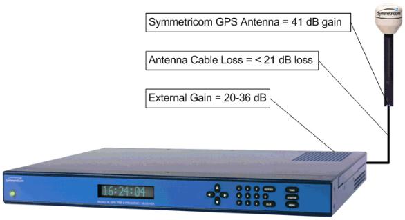
GPS Signal Strength Requirements
Refer to Figure 2:The required gain at the GPS receiver’s ANTENNA connector is greater than 20 dB and less than 36 dB. A standard 150 foot length of RG-59 coax cable of has a loss of 16-21 dB, which meets this requirement. Abide by the minimum input gain requirements if using other cable types.
Additionally, if changing the antenna, abide by the 41 dB gain requirement. Other factors, such as radiation, coverage, VSWR, and input impedance also affect system performance. Symmetricom recommends using the standard antenna and cable provided with the GPS receiver.
Figure 2: GPS Signal Strength Requirements
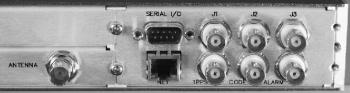
Making Additional Connections
Make the following optional connections:
•ANTENNA: GPS receiver antenna connector with GPS antenna cable. See “GPS Receiver” on page 133 for more information.
Warning: Use a 12-volt capable GPS antenna.
•NET: network port with the Cat-5 network cable (supplied) to an Ethernet network. (Needed to manage the XL-GPS remotely by network, or optionally to distribute NTP time information)
•SERIAL I/O: with RS-232 null modem cable (supplied) to the serial port on a PC.
•For J1, J2, J3, and any other option cards: See also “F110 – J1 Input (TIET)” on page 93, “F111
997-01530-01, Rev. C-25, Jan 2008 |
15 |
S S S S S S S S S S S S S S S S S S S S S S S S S S S S S S S S S S S S S S S S
– J2 Output (Rate, PPO)” on page 96, “F113 – J3 Input (Freq Meas)” on page 100.
Figure 3: Connectors: ANTENNA, SERIAL I/O, J1, J2, J3, NET, 1 PPS, CODE, ALARM
Connecting the Power Supply
Warning: Ensure that a disconnect device, such as a switch, with the appropriate voltage/ current rating is provided when operating/installing the XL-GPS.
Connect the Power Supply it to a power source. The green STATUS light indicates that the XL-GPS is receiving power.
Notes for optional DC power supplies:
•Use a 15 amp circuit breaker in series with the DC power source; don’t connect directly to a DC power source without the breaker.
•14 gage wire is the minimum recommended for DC power source hookup.
•DC Power Supply Only to be used in a restricted access area.
•The screw torque range on the Power Terminal Block is 5 to 8 inch pounds.
•When connecting to a DC power source, first connect the positive power cable to “+” on the power supply, then connect the negative power supply cable to “−”.
Upon receiving power, the XL-GPS goes through its startup sequence; displaying “Booting”, Loading”, and “Starting”. After approximately 40 seconds, the XL-GPS displays the clock status, and user interfaces (front panel/command line) become available.
Configuring the Network Port
The following additional steps are required to make the XL-GPS operational on a network. Make the XLGPS operational on a network if you plan on:
•Managing the XL-GPS remotely over the network
•Distributing timing information from the XL-GPS over the network
Press |
Result |
ENTER |
Displays “FUNCTION” |
100 |
Enters 100 as the function number |
16 |
997-01530-01, Rev. C-25, Jan 2008 |
S S S S S S S S S S S S S S S S S S S S S S S S S S S S S S S S S S S S S S S S
ENTER |
Displays Function 100’s first screen: “COMPANY 00-A0-69…” |
ENTER |
Displays “IP ADDRESS…” |
1-9… |
Enter the unit’s IP Address (e.g., 192.168.0.11 |
ENTER |
Displays “SUBNET MASK…” |
1-9… |
Enter the Subnet Mask (e.g., 255.255.255.000) |
ENTER |
Displays “DEFAULT GATEWAY…” |
1-9… |
Enter the Default Gateway’s IP address (e.g., 192.168.0.1) |
ENTER |
Displays “10 100 BASE-T – 10” |
ENTER |
Displays “REMOTE LOCKOUT – UNLOCK” (Leave unchanged) |
ENTER (5 times) |
Displays “SAVE CHANGES – YES” |
ENTER |
Saves the new network parameters, and reboots the XL-GPS |
Notes:
•To prevent remote network access to the XL-GPS, change Remote Lockout to LOCK. Doing this shuts down remote access through the XL-GPS’s network port so that the XL-GPS’s functions are available only through the keypad interface, and through the serial port’s command line interface.
•For additional information, consult the relevant topics covering the F100 commands in the XLGPS User’s Guide and Reference Manual.
Configuring the Time Display
Configure the XL-GPS to display time correctly. Use the menu-driven keypad interface, to enter the functions and select the desired settings, as follows:
•F1 – Time Zone Offset: (“F: World Map of Time Zones:” on page 141) Set the number of hours difference between your time zone and UTC. For example:
-Pacific Standard Time is UTC -08:00
-Mountain Standard Time is UTC -07:00
-Central Standard Time is UTC -06:00
-Eastern Standard Time is UTC -05:00
•F2 – 12/24-Hour Format: (“F2 – 12/24 Hour Format” on page 35) Select a 12 or 24-hour display format. By default, the XL-GPS is set to the 24-hour display format (e.g., 6 PM is displayed as 18:00).
•F66 – Daylight Saving Time (DST): (“F66 – Daylight Saving Time (DST) Mode” on page 58) If needed, set when Local time enters and leaves DST.
-The factory settings for F66 apply to most users in the continental US: DST begins at 2 am on the first Sunday of April, and ends at 2 am on the last Sunday of October.
-DST is NOT observed in Hawaii, American Samoa, Guam, Puerto Rico, the Virgin Islands,
997-01530-01, Rev. C-25, Jan 2008 |
17 |
S S S S S S S S S S S S S S S S S S S S S S S S S S S S S S S S S S S S S S S S
the Eastern Time Zone portion of the State of Indiana, and most of Arizona (Navajo Indian Reservation in observes DST).
-Throughout the European Union (EU), Summer Time begins and ends at 1 am UTC. It starts the last Sunday in March, and ends the last Sunday in October. In the EU, all time zones change at the same moment.
•F69 – Time Mode: (“F69 – Time Mode” on page 61) Select the type of time output on the front panel display, F8, F9, and F90. The four choices are as follows:
-UTC (Universal Coordinated Time) differs from GPS Time by the addition of leap-second corrections to compensate for variations in the earth’s rotation.
-GPS time is derived directly from the GPS constellation and doesn’t contain any leap-second adjustments or other GPS-to-UTC corrections.
-Standard Time is UTC plus a time zone offset. For example, Pacific Standard Time is UTC minus 8 hours.
-Local Time is UTC with a time zone adjustment and a daylight saving time adjustment.
Using the Command Line Interface
The next two sections show how to connect to the XL-GPS using the serial and network ports. Both Serial I/O and the network port give the user access to the command line interface. While the keypad interface provides a simple menu-driven user interface, the command line interface features:
•Additional functions that aren’t available through the keypad
•Remote accessibility over a network through the standard network port
To use the command line interface, refer to the explanations and examples in the ‘Command Line’ subsections for each function in the XL-GPS User’s Guide and Reference Manual.
Connecting to the Serial Port
Complete the following steps to set up and use the Serial Port to communicate with the XL-GPS.
Verify that the XL-GPS’s serial port settings are as follows: (Keypad: ENTER–4–ENTER. Use the UP/ DOWN ARROWs.)
•Serial Port – RS232
•Baud rate – 9600
•Data bits – 8
•Parity – NONE
•Stop bits – 1
Note: Parity set to NONE is only valid when Data Bits is set to 8.
18 |
997-01530-01, Rev. C-25, Jan 2008 |
S S S S S S S S S S S S S S S S S S S S S S S S S S S S S S S S S S S S S S S S
Connect a null-modem cable from the PC’s serial port to the XL-GPS’s “SERIAL I/O” port.
If needed, configure your PC’s terminal emulation program to match the serial port settings above (9600, 8, N, 1). Set Flow Control to “None”.
One terminal emulation program, HyperTerminal, is usually found in Microsoft Windows under
Programs – Accessories or Programs – Accessories – Communications.
Initiate a serial port connection between the terminal emulation program and the XL-GPS. (The Serial Port connection does not require you to log in.)
Once connected, press the Enter key on your keyboard to get a command prompt.
From the command prompt, “>”, you can use the functions described in the “Function Reference” section of the XL-GPS User’s Guide and Reference Manual. The ‘Command Line’ sub-sections provide instructions and examples.
Troubleshooting Tip: If the terminal emulation software has trouble displaying XL-GPS responses (looks like the unit doesn’t respond to inputs), add a 1 ms/character delay to the software’s serial port settings.
Connecting to the Network Port
The network port provides remote access to the XL-GPS’s command line interface. Complete the following steps to connect to the network port.
1.Use function F100 – Network Port Configuration & XL-GPS Firmware (page 74), or F100 IP – IP Address (page 76), to obtain the XL-GPS’s IP address.
2.Open a telnet session from your PC to the XL-GPS.
-In Windows, click Start – Run, enter telnet ###.###.###.### (where the #s are the XLGPS’s IP address), and click OK.
-Open a telnet session using a program such as HyperTerminal, TeraTerm Pro, or Minicom. Consult the program’s documentation for instructions.
3.Log in as user name “operator” and password, “janus”. Press Enter on your keyboard to get a command prompt.
From the command prompt, “>”, you can use the functions described in the “Function Reference” section of the XL-GPS User’s Guide and Reference Manual. The ‘Command Line’ sub-sections provide instructions and examples.
Related topics:
• |
“Configuring the Network Port” on page 16 |
|
• |
“F100 – Network Port Configuration & XL-GPS Firmware” on page 74 |
|
• |
“F100 L/LOCK/UNLOCK – Remote Lockout” on page 80 |
19 |
997-01530-01, Rev. C-25, Jan 2008 |
||
S S S S S S S S S S S S S S S S S S S S S S S S S S S S S S S S S S S S S S S S
Installing the Expansion Module
Warning: Installing and removing the expansion module can expose dangerous voltages that can cause electric shock resulting in injury or death. Disconnect all power before installing or removing the option card. Dangerous voltages may be present in the expansion module and in the unit even when the power is disconnected.
To install the optional Expansion Module:
1.Set the unit up on a clean, safe, stable work surface that provides good visibility and maneuverability to work with screwdriver.
2.On the back panel, select an option bay and unscrew the retaining screws and remove the small aluminum panel from the bay.
3.Line up the edges of the module with the guide grooves in the option bay and slide it in.
4.When the card is in almost all the way, push it firmly the rest of the way in until the faceplate of the option card is flush with the back panel.
5.Insert and tighten the retaining screws so the expansion module is secured in place.
To remove the expansion module, remove the screws, pull the card out, and secure the small aluminum panel in its place with the screws.
Configuring the Expansion Module
Each of the Expansion Module’s outputs can be independently configured to generate a signal type. This is done using jumpers and switches located on the module. Symmetricom configures the output signals
20 |
997-01530-01, Rev. C-25, Jan 2008 |
Loading...