


 Loading...
TimeProvider 1000 and 1100
Edge Clock
User’s Guide
Revision G – April 2008
Part Number 097-58001-02
Symmetricom, Inc.
2300 Orchard Parkway
San Jose, CA 95131-1017
U.S.A.
http://www.symmetricom.com
Copyright © 2003–2008 Symmetricom, Inc.
All rights reserved. Printed in U.S.A.
All product names, service marks, trademarks, and registered trademarks used in this document are the property of their respective owners.

Table of Contents
Contents
How to Use This Guide
Purpose of This Guide . . . . . . . . . . . . . . . . . . . . . . . . . . . . . . . . . . . . . . . . . . . . . . . . 14 Who Should Read This Guide . . . . . . . . . . . . . . . . . . . . . . . . . . . . . . . . . . . . . . . . . . 14 Structure of This Guide . . . . . . . . . . . . . . . . . . . . . . . . . . . . . . . . . . . . . . . . . . . . . . . 14 Conventions Used in This Guide . . . . . . . . . . . . . . . . . . . . . . . . . . . . . . . . . . . . . . . . 15 Warnings, Cautions, Recommendations, and Notes . . . . . . . . . . . . . . . . . . . . . . . . . 16 Related Documents and Information . . . . . . . . . . . . . . . . . . . . . . . . . . . . . . . . . . . . . 17 Where to Find Answers to Product and Document Questions. . . . . . . . . . . . . . . . . . 17 What’s New in This Guide . . . . . . . . . . . . . . . . . . . . . . . . . . . . . . . . . . . . . . . . . . . . . 17
Chapter 1 Overview of the TimeProvider
Overview . . . . . . . . . . . . . . . . . . . . . . . . . . . . . . . . . . . . . . . . . . . . . . . . . . . . . . . . . . 20
Shelves . . . . . . . . . . . . . . . . . . . . . . . . . . . . . . . . . . . . . . . . . . . . . . . . . . . . . . . 20
Expansion Panel . . . . . . . . . . . . . . . . . . . . . . . . . . . . . . . . . . . . . . . . . . . . . . . . 21
Inputs . . . . . . . . . . . . . . . . . . . . . . . . . . . . . . . . . . . . . . . . . . . . . . . . . . . . . . . . 22
Outputs . . . . . . . . . . . . . . . . . . . . . . . . . . . . . . . . . . . . . . . . . . . . . . . . . . . . . . . 22
Communication . . . . . . . . . . . . . . . . . . . . . . . . . . . . . . . . . . . . . . . . . . . . . . . . . 23
Clocks . . . . . . . . . . . . . . . . . . . . . . . . . . . . . . . . . . . . . . . . . . . . . . . . . . . . . . . . 23
Operating Modes . . . . . . . . . . . . . . . . . . . . . . . . . . . . . . . . . . . . . . . . . . . . . . . . . . . . 23
Performance Monitoring. . . . . . . . . . . . . . . . . . . . . . . . . . . . . . . . . . . . . . . . . . . . . . . 24
Phase Measurements . . . . . . . . . . . . . . . . . . . . . . . . . . . . . . . . . . . . . . . . . . . . 25
MTIE Calculations . . . . . . . . . . . . . . . . . . . . . . . . . . . . . . . . . . . . . . . . . . . . . . . 25
TDEV Calculations . . . . . . . . . . . . . . . . . . . . . . . . . . . . . . . . . . . . . . . . . . . . . . 25
FFOFF Calculations . . . . . . . . . . . . . . . . . . . . . . . . . . . . . . . . . . . . . . . . . . . . . 26
NTP Operation . . . . . . . . . . . . . . . . . . . . . . . . . . . . . . . . . . . . . . . . . . . . . . . . . . . . . . 26
SNMP – Simple Network Management Protocol . . . . . . . . . . . . . . . . . . . . . . . . . . . . 28
Physical Description. . . . . . . . . . . . . . . . . . . . . . . . . . . . . . . . . . . . . . . . . . . . . . . . . . 28
Functional Description . . . . . . . . . . . . . . . . . . . . . . . . . . . . . . . . . . . . . . . . . . . . . . . . 30
System Power . . . . . . . . . . . . . . . . . . . . . . . . . . . . . . . . . . . . . . . . . . . . . . . . . . . . . . 33
Communication Ports. . . . . . . . . . . . . . . . . . . . . . . . . . . . . . . . . . . . . . . . . . . . . . . . . 34
Ethernet. . . . . . . . . . . . . . . . . . . . . . . . . . . . . . . . . . . . . . . . . . . . . . . . . . . . . . . 34
Local Craft Serial Port . . . . . . . . . . . . . . . . . . . . . . . . . . . . . . . . . . . . . . . . . . . . 34
Remote Serial Port . . . . . . . . . . . . . . . . . . . . . . . . . . . . . . . . . . . . . . . . . . . . . . 34
Reference Input Signals. . . . . . . . . . . . . . . . . . . . . . . . . . . . . . . . . . . . . . . . . . . . . . . 34
Selecting the Input. . . . . . . . . . . . . . . . . . . . . . . . . . . . . . . . . . . . . . . . . . . . . . . 35
SSMs and Quality Level . . . . . . . . . . . . . . . . . . . . . . . . . . . . . . . . . . . . . . . . . . 36
GPS Inputs . . . . . . . . . . . . . . . . . . . . . . . . . . . . . . . . . . . . . . . . . . . . . . . . . . . . 38
Clock Performance. . . . . . . . . . . . . . . . . . . . . . . . . . . . . . . . . . . . . . . . . . . . . . . . . . . 39
Output Signals . . . . . . . . . . . . . . . . . . . . . . . . . . . . . . . . . . . . . . . . . . . . . . . . . . . . . . 39
Retimer Modules . . . . . . . . . . . . . . . . . . . . . . . . . . . . . . . . . . . . . . . . . . . . . . . . . . . . 40
097-58001-02 Revision G – April 2008 |
TimeProvider User’s Guide |
3 |

Table of Contents |
|
Alarms . . . . . . . . . . . . . . . . . . . . . . . . . . . . . . . . . . . . . . . . . . . . . . . . . . . . . . . . . . . . |
41 |
Synchronization Status Messages (SSMs) . . . . . . . . . . . . . . . . . . . . . . . . . . . . . . . . |
41 |
SmartClock. . . . . . . . . . . . . . . . . . . . . . . . . . . . . . . . . . . . . . . . . . . . . . . . . . . . . . . . . |
43 |
BesTime . . . . . . . . . . . . . . . . . . . . . . . . . . . . . . . . . . . . . . . . . . . . . . . . . . . . . . . . . . . |
43 |
Normal Tracking . . . . . . . . . . . . . . . . . . . . . . . . . . . . . . . . . . . . . . . . . . . . . . . . |
44 |
GPS Holdover . . . . . . . . . . . . . . . . . . . . . . . . . . . . . . . . . . . . . . . . . . . . . . . . . . |
44 |
Chapter 2 Engineering and Ordering Procedures |
|
Shelf . . . . . . . . . . . . . . . . . . . . . . . . . . . . . . . . . . . . . . . . . . . . . . . . . . . . . . . . . . . . . |
46 |
Model 1000 Front Access . . . . . . . . . . . . . . . . . . . . . . . . . . . . . . . . . . . . . . . . . |
46 |
Model 1100 Rear Access . . . . . . . . . . . . . . . . . . . . . . . . . . . . . . . . . . . . . . . . . |
46 |
Expansion Panel . . . . . . . . . . . . . . . . . . . . . . . . . . . . . . . . . . . . . . . . . . . . . . . . . . . . |
46 |
Front Access . . . . . . . . . . . . . . . . . . . . . . . . . . . . . . . . . . . . . . . . . . . . . . . . . . . |
46 |
Rear Access . . . . . . . . . . . . . . . . . . . . . . . . . . . . . . . . . . . . . . . . . . . . . . . . . . . |
47 |
Input Modules. . . . . . . . . . . . . . . . . . . . . . . . . . . . . . . . . . . . . . . . . . . . . . . . . . . . . . . |
47 |
Output Modules . . . . . . . . . . . . . . . . . . . . . . . . . . . . . . . . . . . . . . . . . . . . . . . . . . . . . |
47 |
IMC and IOC Modules . . . . . . . . . . . . . . . . . . . . . . . . . . . . . . . . . . . . . . . . . . . . . . . . |
48 |
GPS Antenna . . . . . . . . . . . . . . . . . . . . . . . . . . . . . . . . . . . . . . . . . . . . . . . . . . . . . . . |
49 |
Ordering and Parts List . . . . . . . . . . . . . . . . . . . . . . . . . . . . . . . . . . . . . . . . . . . . . . . |
51 |
Ordering the Cable Management Option . . . . . . . . . . . . . . . . . . . . . . . . . . . . . . . . . . |
51 |
Ordering an NTP or SNMP License . . . . . . . . . . . . . . . . . . . . . . . . . . . . . . . . . . . . . . |
51 |
Chapter 3 Installing the TimeProvider |
|
Getting Started . . . . . . . . . . . . . . . . . . . . . . . . . . . . . . . . . . . . . . . . . . . . . . . . . . . . . . |
54 |
Pre-Installation Check . . . . . . . . . . . . . . . . . . . . . . . . . . . . . . . . . . . . . . . . . . . . |
54 |
Performing a Site Survey . . . . . . . . . . . . . . . . . . . . . . . . . . . . . . . . . . . . . . . . . |
54 |
Gathering the Tools. . . . . . . . . . . . . . . . . . . . . . . . . . . . . . . . . . . . . . . . . . . . . . |
55 |
Unpacking the Unit. . . . . . . . . . . . . . . . . . . . . . . . . . . . . . . . . . . . . . . . . . . . . . . . . . . |
56 |
Rack Mounting . . . . . . . . . . . . . . . . . . . . . . . . . . . . . . . . . . . . . . . . . . . . . . . . . . . . . . |
56 |
Making Connections. . . . . . . . . . . . . . . . . . . . . . . . . . . . . . . . . . . . . . . . . . . . . . . . . . |
60 |
Making Ground Connections. . . . . . . . . . . . . . . . . . . . . . . . . . . . . . . . . . . . . . . |
60 |
Making Power Connections. . . . . . . . . . . . . . . . . . . . . . . . . . . . . . . . . . . . . . . . |
61 |
Verifying Power and Grounding Connections . . . . . . . . . . . . . . . . . . . . . . . . . . |
62 |
Making Input Connections. . . . . . . . . . . . . . . . . . . . . . . . . . . . . . . . . . . . . . . . . |
63 |
Making Output Connections . . . . . . . . . . . . . . . . . . . . . . . . . . . . . . . . . . . . . . . |
66 |
Making Retimer Connections . . . . . . . . . . . . . . . . . . . . . . . . . . . . . . . . . . . . . . |
69 |
Making Alarm Connections . . . . . . . . . . . . . . . . . . . . . . . . . . . . . . . . . . . . . . . . |
70 |
Making GPS Connections . . . . . . . . . . . . . . . . . . . . . . . . . . . . . . . . . . . . . . . . . |
71 |
Making Communications Connections . . . . . . . . . . . . . . . . . . . . . . . . . . . . . . . |
79 |
Changing Communications Settings . . . . . . . . . . . . . . . . . . . . . . . . . . . . . . . . . |
80 |
Installing Connections to the Ethernet Port . . . . . . . . . . . . . . . . . . . . . . . . . . . . . . . . |
80 |
Installation Check List . . . . . . . . . . . . . . . . . . . . . . . . . . . . . . . . . . . . . . . . . . . . . . . . |
82 |
Powering Up the Shelf . . . . . . . . . . . . . . . . . . . . . . . . . . . . . . . . . . . . . . . . . . . . . . . . |
82 |
4 |
TimeProvider User’s Guide |
097-58001-02 Revision G – April 2008 |

Table of Contents
Working With Cards . . . . . . . . . . . . . . . . . . . . . . . . . . . . . . . . . . . . . . . . . . . . . . . . . . 82
Properly Handling Cards . . . . . . . . . . . . . . . . . . . . . . . . . . . . . . . . . . . . . . . . . . 82
Inserting Cards . . . . . . . . . . . . . . . . . . . . . . . . . . . . . . . . . . . . . . . . . . . . . . . . . 83
Removing Cards . . . . . . . . . . . . . . . . . . . . . . . . . . . . . . . . . . . . . . . . . . . . . . . . 83
Firmware Features . . . . . . . . . . . . . . . . . . . . . . . . . . . . . . . . . . . . . . . . . . . . . . . . . . . 84
Chapter 4 Provisioning the TimeProvider
TL1 Overview . . . . . . . . . . . . . . . . . . . . . . . . . . . . . . . . . . . . . . . . . . . . . . . . . . . . . . . 86 TL1 Command Structure. . . . . . . . . . . . . . . . . . . . . . . . . . . . . . . . . . . . . . . . . . 86 TL1 Response Format. . . . . . . . . . . . . . . . . . . . . . . . . . . . . . . . . . . . . . . . . . . . 87 Autonomous Messages. . . . . . . . . . . . . . . . . . . . . . . . . . . . . . . . . . . . . . . . . . . 88
Starting the TimeProvider for the First Time . . . . . . . . . . . . . . . . . . . . . . . . . . . . . . . 88 Logging In for the First Time . . . . . . . . . . . . . . . . . . . . . . . . . . . . . . . . . . . . . . . 89
Setting Communications Parameters. . . . . . . . . . . . . . . . . . . . . . . . . . . . . . . . . . . . . 91 Setting RS-232 Parameters . . . . . . . . . . . . . . . . . . . . . . . . . . . . . . . . . . . . . . . 91 Setting Ethernet Parameters. . . . . . . . . . . . . . . . . . . . . . . . . . . . . . . . . . . . . . . 93 Checking Communication Links . . . . . . . . . . . . . . . . . . . . . . . . . . . . . . . . . . . . 94
Defining the Security Parameters . . . . . . . . . . . . . . . . . . . . . . . . . . . . . . . . . . . . . . . 94 Defining a User at the Security Access Level . . . . . . . . . . . . . . . . . . . . . . . . . . 95
Managing the User List . . . . . . . . . . . . . . . . . . . . . . . . . . . . . . . . . . . . . . . . . . . . . . . 96 Logging In . . . . . . . . . . . . . . . . . . . . . . . . . . . . . . . . . . . . . . . . . . . . . . . . . . . . . 96 Logging Out. . . . . . . . . . . . . . . . . . . . . . . . . . . . . . . . . . . . . . . . . . . . . . . . . . . . 97 Adding a User . . . . . . . . . . . . . . . . . . . . . . . . . . . . . . . . . . . . . . . . . . . . . . . . . . 98 Changing the Current User’s Password . . . . . . . . . . . . . . . . . . . . . . . . . . . . . . 99 Displaying a User’s Access Level . . . . . . . . . . . . . . . . . . . . . . . . . . . . . . . . . . . 99 Editing a User’s Access Level. . . . . . . . . . . . . . . . . . . . . . . . . . . . . . . . . . . . . 100 Deleting A User . . . . . . . . . . . . . . . . . . . . . . . . . . . . . . . . . . . . . . . . . . . . . . . . 101 Retrieving Current Users. . . . . . . . . . . . . . . . . . . . . . . . . . . . . . . . . . . . . . . . . 101
Using SynCraft . . . . . . . . . . . . . . . . . . . . . . . . . . . . . . . . . . . . . . . . . . . . . . . . . . . . . 102 Starting SynCraft. . . . . . . . . . . . . . . . . . . . . . . . . . . . . . . . . . . . . . . . . . . . . . . 102 Creating a Connection. . . . . . . . . . . . . . . . . . . . . . . . . . . . . . . . . . . . . . . . . . . 103 Opening a Connection. . . . . . . . . . . . . . . . . . . . . . . . . . . . . . . . . . . . . . . . . . . 104 Closing a Connection . . . . . . . . . . . . . . . . . . . . . . . . . . . . . . . . . . . . . . . . . . . 104
Provisioning the IOC . . . . . . . . . . . . . . . . . . . . . . . . . . . . . . . . . . . . . . . . . . . . . . . . 105 Setting the System Mode . . . . . . . . . . . . . . . . . . . . . . . . . . . . . . . . . . . . . . . . 105 Setting the IOC Parameters . . . . . . . . . . . . . . . . . . . . . . . . . . . . . . . . . . . . . . 107
Provisioning the Input Reference . . . . . . . . . . . . . . . . . . . . . . . . . . . . . . . . . . . . . . . 108 Setting the Input State. . . . . . . . . . . . . . . . . . . . . . . . . . . . . . . . . . . . . . . . . . . 108 Setting the GPS Parameters. . . . . . . . . . . . . . . . . . . . . . . . . . . . . . . . . . . . . . 109 Setting the Input Frequency . . . . . . . . . . . . . . . . . . . . . . . . . . . . . . . . . . . . . . 110 Setting the Input Frame Type . . . . . . . . . . . . . . . . . . . . . . . . . . . . . . . . . . . . . 110 Controlling Automatic Reference Switching . . . . . . . . . . . . . . . . . . . . . . . . . . 111 Setting the Input Quality Level . . . . . . . . . . . . . . . . . . . . . . . . . . . . . . . . . . . . 112 Setting the Input Priority Level . . . . . . . . . . . . . . . . . . . . . . . . . . . . . . . . . . . . 113 Manually Selecting the Reference. . . . . . . . . . . . . . . . . . . . . . . . . . . . . . . . . . 114 Provisioning the SSM . . . . . . . . . . . . . . . . . . . . . . . . . . . . . . . . . . . . . . . . . . . 115
097-58001-02 Revision G – April 2008 |
TimeProvider User’s Guide |
5 |

Table of Contents
Enabling CRC4 . . . . . . . . . . . . . . . . . . . . . . . . . . . . . . . . . . . . . . . . . . . . . . . . 116
Using Performance Monitoring . . . . . . . . . . . . . . . . . . . . . . . . . . . . . . . . . . . . 116
Provisioning the Outputs . . . . . . . . . . . . . . . . . . . . . . . . . . . . . . . . . . . . . . . . . . . . . 118
Enabling and Disabling the Outputs . . . . . . . . . . . . . . . . . . . . . . . . . . . . . . . . 119
Provisioning the Output Framing Type . . . . . . . . . . . . . . . . . . . . . . . . . . . . . . 119
Provisioning Retimer Parameters . . . . . . . . . . . . . . . . . . . . . . . . . . . . . . . . . . . . . . 120
Enabling and Disabling the Retimers . . . . . . . . . . . . . . . . . . . . . . . . . . . . . . . 120
Provisioning the LBO. . . . . . . . . . . . . . . . . . . . . . . . . . . . . . . . . . . . . . . . . . . . 121
Provisioning Cut-thru Mode. . . . . . . . . . . . . . . . . . . . . . . . . . . . . . . . . . . . . . . 122
Provisioning NTP Parameters . . . . . . . . . . . . . . . . . . . . . . . . . . . . . . . . . . . . . . . . . 122
Activating NTP. . . . . . . . . . . . . . . . . . . . . . . . . . . . . . . . . . . . . . . . . . . . . . . . . 123
Editing NTP Peer Server Parameters . . . . . . . . . . . . . . . . . . . . . . . . . . . . . . . 123
Enabling NTP Authentication . . . . . . . . . . . . . . . . . . . . . . . . . . . . . . . . . . . . . 124
Setting the NTP Authentication Key . . . . . . . . . . . . . . . . . . . . . . . . . . . . . . . . 125
Provisioning Alarms . . . . . . . . . . . . . . . . . . . . . . . . . . . . . . . . . . . . . . . . . . . . . . . . . 126
Provisioning the Alarm Levels. . . . . . . . . . . . . . . . . . . . . . . . . . . . . . . . . . . . . 126
Provisioning System-Level Alarms . . . . . . . . . . . . . . . . . . . . . . . . . . . . . . . . . 130
Retrieving Current Alarm Settings. . . . . . . . . . . . . . . . . . . . . . . . . . . . . . . . . . 131
Retrieving Current Alarms . . . . . . . . . . . . . . . . . . . . . . . . . . . . . . . . . . . . . . . . 132
Displaying Alarm Status . . . . . . . . . . . . . . . . . . . . . . . . . . . . . . . . . . . . . . . . . 134
Clearing Alarms. . . . . . . . . . . . . . . . . . . . . . . . . . . . . . . . . . . . . . . . . . . . . . . . 135
Provisioning SNMP Parameters. . . . . . . . . . . . . . . . . . . . . . . . . . . . . . . . . . . . . . . . 136
Activating SNMP . . . . . . . . . . . . . . . . . . . . . . . . . . . . . . . . . . . . . . . . . . . . . . . 136
Adding a User . . . . . . . . . . . . . . . . . . . . . . . . . . . . . . . . . . . . . . . . . . . . . . . . . 137
Changing A User’s Security Parameters. . . . . . . . . . . . . . . . . . . . . . . . . . . . . 137
Displaying the Connected Users. . . . . . . . . . . . . . . . . . . . . . . . . . . . . . . . . . . 137
Deleting a User . . . . . . . . . . . . . . . . . . . . . . . . . . . . . . . . . . . . . . . . . . . . . . . . 137
Setting Up SNMP Traps, Informs, and Notifications . . . . . . . . . . . . . . . . . . . . 137
System Commands . . . . . . . . . . . . . . . . . . . . . . . . . . . . . . . . . . . . . . . . . . . . . . . . . 138
Displaying Events . . . . . . . . . . . . . . . . . . . . . . . . . . . . . . . . . . . . . . . . . . . . . . 138
Displaying the Configuration of the TimeProvider . . . . . . . . . . . . . . . . . . . . . . 139
Restarting the TimeProvider . . . . . . . . . . . . . . . . . . . . . . . . . . . . . . . . . . . . . . 140
Saving Provisioning Data . . . . . . . . . . . . . . . . . . . . . . . . . . . . . . . . . . . . . . . . . . . . . 141
Chapter 5 Testing the TimeProvider
Testing the TimeProvider . . . . . . . . . . . . . . . . . . . . . . . . . . . . . . . . . . . . . . . . . . . . . 146
Test Overview . . . . . . . . . . . . . . . . . . . . . . . . . . . . . . . . . . . . . . . . . . . . . . . . . 146
Test Equipment . . . . . . . . . . . . . . . . . . . . . . . . . . . . . . . . . . . . . . . . . . . . . . . . 146
Verifying Normal Operation . . . . . . . . . . . . . . . . . . . . . . . . . . . . . . . . . . . . . . . . . . . 146
Testing Alarm Conditions . . . . . . . . . . . . . . . . . . . . . . . . . . . . . . . . . . . . . . . . . . . . . 148
Testing the IOC Operating Modes. . . . . . . . . . . . . . . . . . . . . . . . . . . . . . . . . . 148
Testing the Reference Switching. . . . . . . . . . . . . . . . . . . . . . . . . . . . . . . . . . . 149
Testing the Non-Revertive Operating Mode . . . . . . . . . . . . . . . . . . . . . . . . . . 149
Testing the Revertive Operating Mode . . . . . . . . . . . . . . . . . . . . . . . . . . . . . . 150
Testing the Power Alarms . . . . . . . . . . . . . . . . . . . . . . . . . . . . . . . . . . . . . . . . 150
Detecting Input Errors . . . . . . . . . . . . . . . . . . . . . . . . . . . . . . . . . . . . . . . . . . . 151
6 |
TimeProvider User’s Guide |
097-58001-02 Revision G – April 2008 |

Table of Contents
Testing the Communication Ports . . . . . . . . . . . . . . . . . . . . . . . . . . . . . . . . . . . . . . 151
Testing the Local Craft Serial Port . . . . . . . . . . . . . . . . . . . . . . . . . . . . . . . . . 151
Testing the Remote Serial Port . . . . . . . . . . . . . . . . . . . . . . . . . . . . . . . . . . . . 152
Testing the Ethernet Port . . . . . . . . . . . . . . . . . . . . . . . . . . . . . . . . . . . . . . . . 152
Testing the Outputs . . . . . . . . . . . . . . . . . . . . . . . . . . . . . . . . . . . . . . . . . . . . . . . . . 153
Test Record . . . . . . . . . . . . . . . . . . . . . . . . . . . . . . . . . . . . . . . . . . . . . . . . . . . . . . . 153
Chapter 6 Maintaining and Troubleshooting the TimeProvider
Preventive Maintenance. . . . . . . . . . . . . . . . . . . . . . . . . . . . . . . . . . . . . . . . . . . . . . 156 Safety Considerations . . . . . . . . . . . . . . . . . . . . . . . . . . . . . . . . . . . . . . . . . . . . . . . 156 ESD Considerations. . . . . . . . . . . . . . . . . . . . . . . . . . . . . . . . . . . . . . . . . . . . . . . . . 156
Diagnosing the IOC . . . . . . . . . . . . . . . . . . . . . . . . . . . . . . . . . . . . . . . . . . . . . . . . . 157 Reading LED Conditions. . . . . . . . . . . . . . . . . . . . . . . . . . . . . . . . . . . . . . . . . 157 Interpreting Error Messages . . . . . . . . . . . . . . . . . . . . . . . . . . . . . . . . . . . . . . 158 Removing the IOC. . . . . . . . . . . . . . . . . . . . . . . . . . . . . . . . . . . . . . . . . . . . . . 158 Replacing the IOC. . . . . . . . . . . . . . . . . . . . . . . . . . . . . . . . . . . . . . . . . . . . . . 160
Diagnosing the IMC . . . . . . . . . . . . . . . . . . . . . . . . . . . . . . . . . . . . . . . . . . . . . . . . . 162 Reading LED Conditions. . . . . . . . . . . . . . . . . . . . . . . . . . . . . . . . . . . . . . . . . 162 Interpreting Error Messages . . . . . . . . . . . . . . . . . . . . . . . . . . . . . . . . . . . . . . 163 Replacing the IMC or IMC/TPIU . . . . . . . . . . . . . . . . . . . . . . . . . . . . . . . . . . . 163
Diagnosing the External TPIU . . . . . . . . . . . . . . . . . . . . . . . . . . . . . . . . . . . . . . . . . 164 Diagnosing the Retimer Module. . . . . . . . . . . . . . . . . . . . . . . . . . . . . . . . . . . . . . . . 164 Replacing Output Modules. . . . . . . . . . . . . . . . . . . . . . . . . . . . . . . . . . . . . . . . . . . . 165 Replacing the Input Module . . . . . . . . . . . . . . . . . . . . . . . . . . . . . . . . . . . . . . . . . . . 166
Troubleshooting the TimeProvider . . . . . . . . . . . . . . . . . . . . . . . . . . . . . . . . . . . . . . 167 Using Events to Troubleshoot . . . . . . . . . . . . . . . . . . . . . . . . . . . . . . . . . . . . . 167 Using Alarm Codes to Troubleshoot . . . . . . . . . . . . . . . . . . . . . . . . . . . . . . . . 176
Repairing the TimeProvider . . . . . . . . . . . . . . . . . . . . . . . . . . . . . . . . . . . . . . . . . . . 187 Obtaining Technical Assistance . . . . . . . . . . . . . . . . . . . . . . . . . . . . . . . . . . . . . . . . 187
Upgrading the Firmware. . . . . . . . . . . . . . . . . . . . . . . . . . . . . . . . . . . . . . . . . . . . . . 187 Upgrading the IMC . . . . . . . . . . . . . . . . . . . . . . . . . . . . . . . . . . . . . . . . . . . . . 189 Upgrading the IOC . . . . . . . . . . . . . . . . . . . . . . . . . . . . . . . . . . . . . . . . . . . . . 189
Returning the TimeProvider . . . . . . . . . . . . . . . . . . . . . . . . . . . . . . . . . . . . . . . . . . . 191 Repacking the Unit . . . . . . . . . . . . . . . . . . . . . . . . . . . . . . . . . . . . . . . . . . . . . 191 Equipment Return Procedure . . . . . . . . . . . . . . . . . . . . . . . . . . . . . . . . . . . . . 192
Manual Updates . . . . . . . . . . . . . . . . . . . . . . . . . . . . . . . . . . . . . . . . . . . . . . . . . . . . 192
Chapter 7 Specifications of the TimeProvider
Communications Ports . . . . . . . . . . . . . . . . . . . . . . . . . . . . . . . . . . . . . . . . . . . . . . . 194
Serial Ports . . . . . . . . . . . . . . . . . . . . . . . . . . . . . . . . . . . . . . . . . . . . . . . . . . . 194
LAN Port . . . . . . . . . . . . . . . . . . . . . . . . . . . . . . . . . . . . . . . . . . . . . . . . . . . . . 195
Clocks . . . . . . . . . . . . . . . . . . . . . . . . . . . . . . . . . . . . . . . . . . . . . . . . . . . . . . . . . . . 195
Inputs . . . . . . . . . . . . . . . . . . . . . . . . . . . . . . . . . . . . . . . . . . . . . . . . . . . . . . . . . . . . 196
097-58001-02 Revision G – April 2008 |
TimeProvider User’s Guide |
7 |

Table of Contents
Outputs. . . . . . . . . . . . . . . . . . . . . . . . . . . . . . . . . . . . . . . . . . . . . . . . . . . . . . . . . . . 198
Alarms . . . . . . . . . . . . . . . . . . . . . . . . . . . . . . . . . . . . . . . . . . . . . . . . . . . . . . . . . . . 200
Input Alarms . . . . . . . . . . . . . . . . . . . . . . . . . . . . . . . . . . . . . . . . . . . . . . . . . . 200
Output Alarms . . . . . . . . . . . . . . . . . . . . . . . . . . . . . . . . . . . . . . . . . . . . . . . . . 200
Power . . . . . . . . . . . . . . . . . . . . . . . . . . . . . . . . . . . . . . . . . . . . . . . . . . . . . . . . . . . . 200
Roof Antenna . . . . . . . . . . . . . . . . . . . . . . . . . . . . . . . . . . . . . . . . . . . . . . . . . . . . . . 201
Mechanical . . . . . . . . . . . . . . . . . . . . . . . . . . . . . . . . . . . . . . . . . . . . . . . . . . . . . . . . 201
TimeProvider 1000 Front-Access Shelf. . . . . . . . . . . . . . . . . . . . . . . . . . . . . . 201
TimeProvider 1100 Rear-Access Shelf . . . . . . . . . . . . . . . . . . . . . . . . . . . . . . 201
Environmental . . . . . . . . . . . . . . . . . . . . . . . . . . . . . . . . . . . . . . . . . . . . . . . . . . . . . 202
Default Command Access Levels . . . . . . . . . . . . . . . . . . . . . . . . . . . . . . . . . . . . . . 204
Alarm Default Values . . . . . . . . . . . . . . . . . . . . . . . . . . . . . . . . . . . . . . . . . . . . . . . . 205
Default Equipment Parameters . . . . . . . . . . . . . . . . . . . . . . . . . . . . . . . . . . . . . . . . 208
Default Input Parameters . . . . . . . . . . . . . . . . . . . . . . . . . . . . . . . . . . . . . . . . . . . . . 209
Default Output Parameters . . . . . . . . . . . . . . . . . . . . . . . . . . . . . . . . . . . . . . . . . . . 210
Default Retimer Parameters. . . . . . . . . . . . . . . . . . . . . . . . . . . . . . . . . . . . . . . . . . . 211
Overview . . . . . . . . . . . . . . . . . . . . . . . . . . . . . . . . . . . . . . . . . . . . . . . . . . . . . . . . . 214
System Requirements . . . . . . . . . . . . . . . . . . . . . . . . . . . . . . . . . . . . . . . . . . . . . . . 214
Installing SynCraft . . . . . . . . . . . . . . . . . . . . . . . . . . . . . . . . . . . . . . . . . . . . . . . . . . 215
Index
8 |
TimeProvider User’s Guide |
097-58001-02 Revision G – April 2008 |

|
Table of Contents |
|
Figures |
|
|
1-1 |
TimeProvider 1000 ETSI-style Shelf. . . . . . . . . . . . . . . . . . . . . . . . . . . . . . . |
21 |
1-2 |
TimeProvider 1100 Rear Access Shelf . . . . . . . . . . . . . . . . . . . . . . . . . . . . . |
21 |
1-3 |
TimeProvider 1100 Expansion Panel . . . . . . . . . . . . . . . . . . . . . . . . . . . . . . |
22 |
1-4 |
Front Panel of the TimeProvider 1000 . . . . . . . . . . . . . . . . . . . . . . . . . . . . . |
29 |
1-5 |
Rear Panel of the TimeProvider 1100 – Old Version . . . . . . . . . . . . . . . . . . |
29 |
1-6 |
Rear Panel of the TimeProvider 1100 – New Version. . . . . . . . . . . . . . . . . . |
30 |
1-7 |
Block Diagram of the TimeProvider . . . . . . . . . . . . . . . . . . . . . . . . . . . . . . . |
31 |
1-8 |
The TimeProvider Interface Unit (TPIU) . . . . . . . . . . . . . . . . . . . . . . . . . . . . |
38 |
1-9 |
The Integrated IMC/TPIU . . . . . . . . . . . . . . . . . . . . . . . . . . . . . . . . . . . . . . . |
38 |
3-1 |
Installing the Model 1000 Shelf, Expansion Panel, and Cable Management |
|
|
tray – 19-inch Rack. . . . . . . . . . . . . . . . . . . . . . . . . . . . . . . . . . . . . . . . . . . . |
57 |
3-2 |
Installing the Model 1100 Shelf, Cable Management tray, and Expansion |
|
|
Panel – 19-inch Rack . . . . . . . . . . . . . . . . . . . . . . . . . . . . . . . . . . . . . . . . . . |
58 |
3-3 |
Installing the Model 1000 Shelf and Expansion Panel – 23-inch Rack. . . . . |
59 |
3-4 |
Installing the Model 1100 Shelf and Expansion Panel – 23-inch Rack . . . . . |
60 |
3-5 |
Power Terminal Connectors . . . . . . . . . . . . . . . . . . . . . . . . . . . . . . . . . . . . . |
62 |
3-6 |
Assembling the ETSI (Front Access) Power Connector . . . . . . . . . . . . . . . . |
62 |
3-7 |
BNC Input Module . . . . . . . . . . . . . . . . . . . . . . . . . . . . . . . . . . . . . . . . . . . . |
63 |
3-8 |
Wire-Wrap Input Module. . . . . . . . . . . . . . . . . . . . . . . . . . . . . . . . . . . . . . . . |
64 |
3-9 |
DB9 Input Module . . . . . . . . . . . . . . . . . . . . . . . . . . . . . . . . . . . . . . . . . . . . . |
64 |
3-10 |
BT43 Input Module . . . . . . . . . . . . . . . . . . . . . . . . . . . . . . . . . . . . . . . . . . . . |
65 |
3-11 |
Metric (Siemens) Input Module. . . . . . . . . . . . . . . . . . . . . . . . . . . . . . . . . . . |
65 |
3-12 |
BNC and Wire-Wrap Output Modules. . . . . . . . . . . . . . . . . . . . . . . . . . . . . . |
67 |
3-13 |
DB9 Output Modules . . . . . . . . . . . . . . . . . . . . . . . . . . . . . . . . . . . . . . . . . . |
67 |
3-14 |
BT43 and Metric (Siemens) Output Modules . . . . . . . . . . . . . . . . . . . . . . . . |
68 |
3-15 |
B-422 Output Module . . . . . . . . . . . . . . . . . . . . . . . . . . . . . . . . . . . . . . . . . . |
68 |
3-16 |
Front Panel of the T1 (wire-wrap) and E1 (BNC) Retimer Modules . . . . . . . |
69 |
3-17 |
Sample Installation Schematic for a Retimer . . . . . . . . . . . . . . . . . . . . . . . . |
69 |
3-18 |
DB-25 Alarm Connector (Front View) . . . . . . . . . . . . . . . . . . . . . . . . . . . . . . |
71 |
3-19 |
Locating the GPS Antenna . . . . . . . . . . . . . . . . . . . . . . . . . . . . . . . . . . . . . . |
71 |
3-20 |
Antenna-to-Shelf Cabling . . . . . . . . . . . . . . . . . . . . . . . . . . . . . . . . . . . . . . . |
73 |
3-21 |
Installing the Antenna Bracket on a Pipe . . . . . . . . . . . . . . . . . . . . . . . . . . . |
74 |
3-22 |
Installing the Antenna Bracket on a Post . . . . . . . . . . . . . . . . . . . . . . . . . . . |
74 |
3-23 |
Attaching the Antenna to the Bracket . . . . . . . . . . . . . . . . . . . . . . . . . . . . . . |
75 |
3-24 |
Assembling the Lightning Suppressor . . . . . . . . . . . . . . . . . . . . . . . . . . . . . |
76 |
3-25 |
Mounting the TPIU and Expansion Panel on the Same Rack Ears . . . . . . . |
78 |
3-26 |
Mounting the TPIU with a Model 1000 ETSI-Style Shelf . . . . . . . . . . . . . . . |
78 |
4-1 |
The SynCraft Main Window . . . . . . . . . . . . . . . . . . . . . . . . . . . . . . . . . . . . . |
102 |
4-2 |
The Create New Connection Window. . . . . . . . . . . . . . . . . . . . . . . . . . . . . . |
103 |
4-3 |
Logical View of the TimeProvider . . . . . . . . . . . . . . . . . . . . . . . . . . . . . . . . . |
104 |
097-58001-02 Revision G – April 2008 |
TimeProvider User’s Guide |
9 |

Table of Contents
10 TimeProvider User’s Guide |
097-58001-02 Revision G – April 2008 |
|
|
Table of Contents |
Tables |
|
|
1-1 |
Typical Power Consumption . . . . . . . . . . . . . . . . . . . . . . . . . . . . . . . |
. . . . . . . .33 |
1-2 |
SSU-Based Reference Selection Scenarios. . . . . . . . . . . . . . . . . . . |
. . . . . . . .37 |
1-3 |
Subtending-Based Reference Selection Scenarios . . . . . . . . . . . . . |
. . . . . . . .37 |
1-4 |
ANSI SSM Quality Level Definitions . . . . . . . . . . . . . . . . . . . . . . . . . |
. . . . . . . .41 |
1-5 |
ITU SSM Quality Level Definitions . . . . . . . . . . . . . . . . . . . . . . . . . . |
. . . . . . . .42 |
2-1 |
Input Modules Available for the TimeProvider . . . . . . . . . . . . . . . . . |
. . . . . . . .47 |
2-2 |
Output Modules and Accessories Available for the TimeProvider . . |
. . . . . . . .47 |
2-3 |
IOC and IMC Modules Available for the TimeProvider . . . . . . . . . . . |
. . . . . . . .48 |
2-4 |
GPS Parts and Accessories . . . . . . . . . . . . . . . . . . . . . . . . . . . . . . . |
. . . . . . . .49 |
2-5 |
TimeProvider Shelves. . . . . . . . . . . . . . . . . . . . . . . . . . . . . . . . . . . . |
. . . . . . . .51 |
3-1 |
Power Connections. . . . . . . . . . . . . . . . . . . . . . . . . . . . . . . . . . . . . . |
. . . . . . . .61 |
3-2 |
Input Connector Modules Available for the IOC . . . . . . . . . . . . . . . . |
. . . . . . . .63 |
3-3 |
Pinout for the DB9 Input Module. . . . . . . . . . . . . . . . . . . . . . . . . . . . |
. . . . . . . .64 |
3-4 |
Output Connector Modules. . . . . . . . . . . . . . . . . . . . . . . . . . . . . . . . |
. . . . . . . .66 |
3-5 |
Pinout for the DB9 Output Module . . . . . . . . . . . . . . . . . . . . . . . . . . |
. . . . . . . .66 |
3-6 |
Alarm Connector Pinout . . . . . . . . . . . . . . . . . . . . . . . . . . . . . . . . . . |
. . . . . . . .70 |
3-7 |
Connector Pinouts for the Serial Ports . . . . . . . . . . . . . . . . . . . . . . . |
. . . . . . . .79 |
3-8 |
Ethernet Communications Port Signal Connections. . . . . . . . . . . . . |
. . . . . . . .81 |
3-9 |
Installation Completeness Checklist . . . . . . . . . . . . . . . . . . . . . . . . . |
. . . . . . . .82 |
3-10 |
Firmware Feature Matrix. . . . . . . . . . . . . . . . . . . . . . . . . . . . . . . . . . |
. . . . . . . .84 |
4-1 |
TL1 Syntax Conventions. . . . . . . . . . . . . . . . . . . . . . . . . . . . . . . . . . |
. . . . . . . .86 |
4-2 |
Default Mask Parameters . . . . . . . . . . . . . . . . . . . . . . . . . . . . . . . . . |
. . . . . . . 117 |
4-3 |
Alarm Conditions and Defaults . . . . . . . . . . . . . . . . . . . . . . . . . . . . . |
. . . . . . .127 |
4-4 |
Provisioning Record . . . . . . . . . . . . . . . . . . . . . . . . . . . . . . . . . . . . . |
. . . . . . .141 |
5-1 |
LED Conditions for the IOC . . . . . . . . . . . . . . . . . . . . . . . . . . . . . . . |
. . . . . . .146 |
5-2 |
LED Conditions for the IMC and IMC/TPIU . . . . . . . . . . . . . . . . . . . |
. . . . . . .147 |
5-3 |
Record of Test Results . . . . . . . . . . . . . . . . . . . . . . . . . . . . . . . . . . . |
. . . . . . .153 |
6-1 |
Preventive Maintenance . . . . . . . . . . . . . . . . . . . . . . . . . . . . . . . . . . |
. . . . . . .156 |
6-2 |
LED Conditions for the IOC . . . . . . . . . . . . . . . . . . . . . . . . . . . . . . . |
. . . . . . .157 |
6-3 |
LED Conditions for the IMC and IMC/TPIU . . . . . . . . . . . . . . . . . . . |
. . . . . . .162 |
6-4 |
LED Conditions for the External TPIU . . . . . . . . . . . . . . . . . . . . . . . |
. . . . . . .164 |
6-5 |
Event Codes . . . . . . . . . . . . . . . . . . . . . . . . . . . . . . . . . . . . . . . . . . . |
. . . . . . .167 |
6-6 |
Set and Clear Conditions for Alarms . . . . . . . . . . . . . . . . . . . . . . . . |
. . . . . . .174 |
6-7 |
Alarm Codes . . . . . . . . . . . . . . . . . . . . . . . . . . . . . . . . . . . . . . . . . . . |
. . . . . . .176 |
6-8 |
Conditions Causing an Event . . . . . . . . . . . . . . . . . . . . . . . . . . . . . . |
. . . . . . .184 |
7-1 |
Serial Port Specifications . . . . . . . . . . . . . . . . . . . . . . . . . . . . . . . . . |
. . . . . . .194 |
7-2 |
Holdover Characteristics. . . . . . . . . . . . . . . . . . . . . . . . . . . . . . . . . . |
. . . . . . .195 |
7-3 |
Hold-in and Pull-in Range. . . . . . . . . . . . . . . . . . . . . . . . . . . . . . . . . |
. . . . . . .196 |
7-4 |
Input Signal Specifications . . . . . . . . . . . . . . . . . . . . . . . . . . . . . . . . |
. . . . . . .197 |
7-5 |
Output Signal Specifications . . . . . . . . . . . . . . . . . . . . . . . . . . . . . . . |
. . . . . . .198 |
7-6 |
Output Alarm Specifications . . . . . . . . . . . . . . . . . . . . . . . . . . . . . . . |
. . . . . . .200 |
097-58001-02 Revision G – April 2008 |
TimeProvider User’s Guide 11 |

Table of Contents
7-7 |
Typical Power Consumption . . . . . . . . . . . . . . . . . . . . . . . . . . . . . . . . . . . . . . |
200 |
7-8 |
Antenna Specifications . . . . . . . . . . . . . . . . . . . . . . . . . . . . . . . . . . . . . . . . . . |
201 |
A-1 |
Default Access Levels for TL1 Commands. . . . . . . . . . . . . . . . . . . . . . . . . . . |
204 |
A-2 |
Default Alarm Settings . . . . . . . . . . . . . . . . . . . . . . . . . . . . . . . . . . . . . . . . . . |
205 |
A-3 |
Default Equipment Parameters. . . . . . . . . . . . . . . . . . . . . . . . . . . . . . . . . . . . |
208 |
A-4 |
Default Input Parameters . . . . . . . . . . . . . . . . . . . . . . . . . . . . . . . . . . . . . . . . |
209 |
A-5 |
Default Output Parameters . . . . . . . . . . . . . . . . . . . . . . . . . . . . . . . . . . . . . . . |
210 |
A-6 |
Default Retimer Parameters . . . . . . . . . . . . . . . . . . . . . . . . . . . . . . . . . . . . . . |
211 |
12 TimeProvider User’s Guide |
097-58001-02 Revision G – April 2008 |

How to Use This Guide
This section describes the format, layout, and purpose of this guide.
In This Preface
Purpose of This Guide
Who Should Read This Guide Structure of This Guide Conventions Used in This Guide
Warnings, Cautions, Recommendations, and Notes Related Documents and Information
Where to Find Answers to Product and Document Questions What’s New in This Guide
097-58001-02 Revision G – April 2008 |
TimeProvider User’s Guide 13 |

How to Use This Guide
Purpose of This Guide
Purpose of This Guide
The TimeProvider User’s Guide describes the procedures for unpacking, installing, using, maintaining, and troubleshooting the Symmetricom TimeProvider. It also includes appendixes that describe default values and how to install the included software application SynCraft.
Who Should Read This Guide
Chapter 1, Overview of the TimeProvider, and Chapter 2, Engineering and Ordering Procedures, are written for non-technical audiences who need general information about the product. Chapter 3, Installing the TimeProvider and subsequent chapters contain technical information about the product. Other chapters and appendixes describe installation, maintenance, and configuration instructions or details primarily intended for qualified maintenance personnel.
Structure of This Guide
This guide contains the following sections and appendixes:
Chapter, Title |
Description |
|
|
Chapter 1, Overview of the |
Provides an overview of the product, describes the major |
TimeProvider |
hardware and software features, and lists the system |
|
specifications. |
|
|
Chapter 2, Engineering and |
Lists the part number and ordering procedure for all |
Ordering Procedures |
TimeProvider parts and accessories. |
|
|
Chapter 3, Installing the |
Contains procedures for unpacking and installing the product. |
TimeProvider |
|
|
|
Chapter 4, Provisioning the |
Describes the TL1 commands required to provision the |
TimeProvider |
TimeProvider after installing the unit. |
|
|
Chapter 5, Testing the |
Provides checklist-based commissioning tests that should be |
TimeProvider |
performed after completing turn-up and software configuration |
|
to ensure the system is ready for normal operation. |
|
|
Chapter 6, Maintaining and |
Contains preventive and corrective maintenance, and |
Troubleshooting the TimeProvider |
troubleshooting procedures for the product. |
|
|
Chapter 7, Specifications of the |
Lists the specifications for the TimeProvider |
TimeProvider |
|
|
|
Appendix A, Factory Default |
Includes a list of the factory default values for hardware and |
Values |
software parameters. |
|
|
14 TimeProvider User’s Guide |
097-58001-02 Revision G – April 2008 |

|
How to Use This Guide |
|
Conventions Used in This Guide |
|
|
Chapter, Title |
Description |
|
|
Appendix B, CRAFT Software |
Describes how to use the CRAFT software interface with the |
Reference |
TimeProvider. |
|
|
Index |
Provides references to individual topics within this guide. |
|
|
Conventions Used in This Guide
This guide uses the following conventions:
Acronyms and Abbreviations – Terms are spelled out the first time they appear in text. Thereafter, only the acronym or abbreviation is used.
Revision Control – The title page lists the printing date and versions of the product this guide describes.
Typographical Conventions – This guide uses the typographical conventions described in the table below.
When text appears |
... it means: |
|
this way... |
||
|
||
|
|
|
TimeProvider User’s Guide |
The title of a document. |
|
|
|
|
SSU |
An operating mode, alarm state, status, or chassis label. |
|
CRITICAL |
|
|
IOC1 |
|
|
|
|
|
Select File, Open... |
Click the Open option on the File menu. |
|
|
|
|
Press Enter |
A named keyboard key. |
|
Press ; |
The key name is shown as it appears on the keyboard. An |
|
|
explanation of the key’s acronym or function immediately follows |
|
|
the first reference to the key, if required. |
|
|
|
|
TimeProvider |
Text in a source file or a system prompt or other text that appears |
|
Username: |
on a screen. |
|
PING |
A command you enter at a system prompt or text you enter in |
|
STATUS |
response to a program prompt. You must enter commands for |
|
|
case-sensitive operating systems exactly as shown. |
|
A re-timing application |
A word or term being emphasized. |
|
|
|
|
Symmetricom does not |
A word or term given special emphasis. |
|
recommend... |
|
|
|
|
|
Structure of This Guide, on |
The blue text, when viewed in a pdf file, indicates a hyperlink to the |
|
page 14 |
indicated text. |
|
|
|
097-58001-02 Revision G – April 2008 |
TimeProvider User’s Guide 15 |

How to Use This Guide
Warnings, Cautions, Recommendations, and Notes
Warnings, Cautions, Recommendations, and Notes
Warnings, Cautions, Recommendations, and Notes attract attention to essential or critical information in this guide. The types of information included in each are explained in the following examples.
Warning: To avoid serious personal injury or death, do not disregard warnings. All warnings use this symbol. Warnings are installation, operation, or maintenance procedures, practices, or statements, that if not strictly observed, may result in serious personal injury or even death.
Caution: To avoid personal injury, do not disregard cautions. All cautions use this symbol. Cautions are installation, operation, or maintenance procedures, practices, conditions, or statements, that if not strictly observed, may result in damage to, or destruction of, the equipment. Cautions are also used to indicate a long-term health hazard.
ESD Caution: To avoid personal injury and electrostatic discharge (ESD) damage to equipment, do not disregard ESD cautions. All ESD cautions use this symbol. ESD cautions are installation, operation, or maintenance procedures, practices, conditions, or statements that if not strictly observed, may result in possible personal injury, electrostatic discharge damage to, or destruction of, static sensitive components of the equipment.
Electrical Shock Caution: To avoid electrical shock and possible personal injury, do not disregard electrical shock cautions. All electrical shock cautions use this symbol. Electrical shock cautions are practices, procedures, or statements, that if not strictly observed, may result in possible personal injury, electrical shock damage to, or destruction of components of the equipment.
Recommendation: All recommendations use this symbol. Recommendations indicate manufacturer-tested methods or known functionality. Recommendations contain installation, operation, or maintenance procedures, practices, conditions, or statements, that provide important information for optimum performance results.
Note: All notes use this symbol. Notes contain installation, operation, or maintenance procedures, practices, conditions, or statements, that alert you to important information, which may make your task easier or increase your understanding.
16 TimeProvider User’s Guide |
097-58001-02 Revision G – April 2008 |

How to Use This Guide
Related Documents and Information
Related Documents and Information
Other helpful documents and software tools are listed below. See your Symmetricom representative or sales office for a complete list of available documentation.
TimeCraft management software – Help files within the application
TimePictra management software – See the User’s manual provided on the system CD
TimeProvider TL1 Reference Guide, part number 097-58001-01 Software Release Notice, part number 097-58001-24
Note: Symmetricom offers a number of applicable training courses designed to enhance product usability. Contact your local representative or sales office for a complete list of courses and outlines.
Where to Find Answers to Product and Document Questions
For additional information about the products described in this guide, please contact your Symmetricom representative or your local sales office. You can also contact us on the web at www.symmetricom.com.
What’s New in This Guide
No Revision F of this guide has been issued. Revision G of this guide includes the following new information:
Added SNMP – Simple Network Management Protocol, on page 28. Corrected the Transit Node traceable row in Table 1-4.
Added the Synchronized - Traceability Unknown row to Table 1-5.
Revised Ordering an NTP or SNMP License, on page 51, to include SNMP. Updated Table 3-10 to include the latest firmware release.
Renamed IP Subnet address to Subnet mask and removed IP Host entries from Table 4-4.
Removed the shims from the drawing in Figure 3-23 and the text in step 5 on page 74.
097-58001-02 Revision G – April 2008 |
TimeProvider User’s Guide 17 |

How to Use This Guide
What’s New in This Guide
Added the latest firmware revisions to Table 3-10.
Revised the order of the steps in Starting the TimeProvider for the First Time, on page 88.
Revised the text in the first paragraph of Logging In for the First Time, on page 89.
Added the 115200 baud rate to Setting the Baud Rate, on page 91, and Table 6-5.
Corrected the length of the password in Managing the User List, on page 96. Added metric values to the table in Provisioning the LBO, on page 121. Corrected the EXDSC alarm description in Table 4-3.
Added the GPSCLRDEL and GPSFLTDEL keywords to the table in Provisioning System-Level Alarms, on page 130.
Added Provisioning SNMP Parameters, on page 136.
Added the GPSCLRDEL and GPSFLTDEL keywords to Table 4-4. Added “GPS faults” to the list in Detecting Input Errors, on page 151.
Added GPSCLRDEL and GPSFLTDEL to Table 6-5, Table 6-8, and Table A-4.
18 TimeProvider User’s Guide |
097-58001-02 Revision G – April 2008 |

Chapter 1 Overview of the TimeProvider
This chapter describes the TimeProvider product.
In This Chapter
Overview
Operating Modes
Performance Monitoring
NTP Operation
SNMP – Simple Network Management Protocol
Physical Description
Functional Description
System Power
Communication Ports
Reference Input Signals
Clock Performance
Output Signals
Alarms
Synchronization Status Messages (SSMs)
SmartClock
BesTime
097-58001-02 Revision G – April 2008 |
TimeProvider User’s Guide 19 |

Chapter 1 Overview of the TimeProvider
Overview
Overview
The TimeProvider is Synchronization Supply Unit (SSU) designed specifically to meet the needs at the network edge. In small offices where core office synchronization solutions are critical, an edge clock like the TimeProvider is ideal because of its compact size and flexibility. Using the integrated GPS features, you can use the TimeProvider in a “small” Central Office to act as a Primary Reference Source (PRS).
The TimeProvider’s unique design incorporates the input, output, and clock functions in a single card, available with either a Rubidium or quartz oscillator. This allows you to simplify the storage inventory required for future expansion needs. The TimeProvider shelf requires only three plug-in cards to operate with full redundancy: dual Input/Output/Clock cards (IOCs) and a single Information Management Card (IMC), which serves as a communications/alarm interface. When dual IOCs are installed, you can mix any combination of Rubidium and quartz oscillators (for example, Rb/Rb, Rb/Qz, or Qz/Qz) to the needs of the network. The main shelf provides up to 32 redundant universal timing outputs; an optional Expansion Panel provides an additional 32 redundant outputs.
Using Symmetricom’s SmartClock™ technology design, the oscillators within the IOCs are enhanced with improved performance and accuracy. Using intelligent firmware algorithms, SmartClock “learns” the effects of the ageing of the clock while it is locked to a reference signal and stores this information in its memory. If the reference signals are lost or disqualified, SmartClock uses the stored data to compensate for frequency changes while the TimeProvider continues to distribute highly stable synchronization signals.
The TimeProvider also uses Symmetricom’s BesTime® algorithm when the GPS input is activated. By using other inputs as references, Bestime calculates and determines a weighting factor for each of the inputs and ensembles them in the overall timing scheme to provide very accurate timing outputs. In the event of GPS signal loss, BesTime continues to predict GPS timing information to provide reliable system timing outputs and holdover performance, ensuring that system reliability is maintained. See BesTime, on page 43 for more information.
Shelves
The TimeProvider is available in two shelf models. Each shelf supports up to 32 redundant output channels.
The TimeProvider 1000 is a 175 mm tall ETSI shelf that meets the requirements of ETSI 300 119-4 January 1994. Figure 1-1 shows the TimeProvider 1000 shelf.
The TimeProvider 1100 is a 130 mm tall rear-access shelf; indicators are on the front panel and connections are available on the rear panel. Figure 1-2 shows the front panel of the TimeProvider 1100.
20 TimeProvider User’s Guide |
097-58001-02 Revision G – April 2008 |
Chapter 1 Overview of the TimeProvider
Overview
Figure 1-1. TimeProvider 1000 ETSI-style Shelf
Figure 1-2. TimeProvider 1100 Rear Access Shelf
Expansion Panel
The TimeProvider has an optional Expansion Panel that doubles (to 64) the number of output channels available. Figure 1-3 shows the rear-access version of the Expansion Panel. The Expansion Panel receives timing signals from the TimeProvider main shelf through an expansion cable. The Expansion Panel provides four groups (A through D) of eight signals; each group is automatically provisioned to the same output signal type as the corresponding group on the main shelf.
097-58001-02 Revision G – April 2008 |
TimeProvider User’s Guide 21 |

Chapter 1 Overview of the TimeProvider
Overview
Figure 1-3. TimeProvider 1100 Expansion Panel
Inputs
The TimeProvider accepts the following types of input signals:
Primary Reference Signals (PRS): 1.544 MHz, 2.048 MHz, 5 MHz, 6.312 MHz, or 10 MHz
Span input signals:
–E1 or 2.048 MHz analog; user-selectable CAS or CCS framing
–T1 D4, Extended Superframe (ESF)
–1.544 and 6.312 MHz
–Composite Clock, including Japan Composite Clock (JCC) and Japan Composite Clock with 400 Hz (JCC4) signals
GPS input:
–GPS signal from the stand-alone TimeProvider Interface Unit (TPIU)
–GPS signal into the TPIU integrated with the IMC (IMC/TPIU card)
The TimeProvider qualifies the input reference signals and detects the following errors: Loss of Signal (LOS), Alarm Indication Signal (AIS), Loss of Framing, and Synchronization Status Messages (SSM) where applicable. Reference Input Signals, on page 34, describes the inputs in more detail.
Outputs
The TimeProvider produces a variety of outputs to meet different signal standards. Output signal types include 8 kHz, 1.544 MHz, 2.048 MHz, 6.312 MHz, E1, T1, CC, JCC, JCC4, and TIA/EIA-B-422 (1.544 and 2.048 MHz). The E1 and T1 signals can be provisioned with standard framing that meets G.703 formats. The SSM bit location is user-selectable on E1 outputs; CRC4 must be enabled in order to provide output SSMs. These outputs are available through one of several different connector panels. See Output Signals, on page 39, for more information on output signals.
22 TimeProvider User’s Guide |
097-58001-02 Revision G – April 2008 |

Chapter 1 Overview of the TimeProvider
Operating Modes
The TimeProvider outputs are arranged into four groups of eight outputs per group in the Main shelf and four groups of eight outputs per group in the optional Expansion panel. Each group is labeled A, B, C, and D, and can be configured independently.
Communication
Three communications ports provide access to the TimeProvider: Ethernet, local Craft serial port, and a Remote serial port. These ports are described in detail in Communication Ports, on page 34.
Clocks
The TimeProvider’s clock design includes a highly stable ovenized Quartz crystal or Rubidium oscillator with Direct Digital Synthesis (DDS) to produce accurate synchronization outputs. In a dual-IOC configuration, the clock function is redundant to provide protection, and you can mix and choose any combination of Quartz and Rubidium oscillator to meet the needs of the network. Each IOC qualifies the input signal and filters jitter and wander noise elements that may exist. In the event that all input references are lost or disqualified, the TimeProvider’s clock design, together with the SmartClock technology, goes into holdover mode with the oscillator providing the system reference.
The Rubidium IOC meets Stratum 2/Type II performance; the Quartz IOC meets Stratum 3E/Type I performance.
Operating Modes
You can configure the TimeProvider to operate in one of three modes: Synchronization Supply Unit (SSU), Subtending (SUB) as defined by Telcordia GR-378 Section 7, or Primary Reference Receiver (PRR) when the GPS input is available. Each mode is unique in its operation, and is defined in the following paragraphs.
SSU Mode
This is the TimeProvider’s default operating mode. You can select the system reference from any valid input on the PRS, INP1, INP2, or GPS connectors.
The GPS input operates as another input reference to the TimeProvider and is treated in the same manner as all other input references (PRS, INP1, or INP2). If the GPS input is active but later becomes disqualified, then the TimeProvider switches to the next available input reference according to the switching rules (Priority, SSM, etc.). If there are no other qualified inputs, then the TimeProvider enters the holdover state until an input is requalified.
097-58001-02 Revision G – April 2008 |
TimeProvider User’s Guide 23 |

Chapter 1 Overview of the TimeProvider
Performance Monitoring
In the SSU mode, the INP1 and INP2 inputs cannot be provisioned to receive Composite Clock (CC) signals, including JCC or JCC4. The method of selecting the system reference is described in Selecting the Input, on page 35.
SUB Mode
This mode allows the TimeProvider to operate as a Remote shelf where phase is critical. When you select the SUB mode, INP1 and INP2 are automatically set for CC inputs (including JCC and JCC4). Outputs provisioned for CC are phase-aligned with the selected CC input reference. Other output types comply with G.703 and GR-1244.
To configure the TimeProvider for Subtending mode, see Setting the System Mode, on page 105.
PRR Mode
In PRR mode, the GPS is automatically selected as the system reference input. This requires that you connect a GPS signal to the TimeProvider through either:
the standalone TPIU (used with Antenna Kits 990-58545-01 or 990-58545-02) or
the integrated IMC/TPIU card (used with Antenna Kits 990-58545-03 or 990-58545-04)
This mode complies with ITU-T G.811 and Telcordia GR-2830 requirements for Primary Reference Receivers/Clocks. Valid signals on the PRS, INP1, or INP2 connectors are used in conjunction with BesTime to extend compliance with GR-2830/G.811 standards.
The PRR mode uses Symmetricom’s BesTime servo control that allows the TimeProvider to continue providing outputs in case GPS tracking is lost, the GPS data loses integrity, or if the IMC is removed from the shelf. BesTime, on page 43 provides more information on the BesTime technology.
To configure the TimeProvider for PRR mode, see Setting the System Mode, on page 105.
Performance Monitoring
The TimeProvider can monitor and qualify all enabled input signals based on phase measurements. It measures the phase differences between the inputs and the output of the corrected clock. From these phase measurements, the TimeProvider computes frequency offset and wander of the input signals. Wander is reported in terms of Maximum Time Interval Error (MTIE) and Time Deviation (TDEV) and creates phase, MTIE, TDEV, and Fractional Frequency Offset (FFOFF) reports. Performance data is automatically gathered on all enabled or monitored inputs.
24 TimeProvider User’s Guide |
097-58001-02 Revision G – April 2008 |

Chapter 1 Overview of the TimeProvider
Performance Monitoring
Using MTIE and FFOFF data, the TimeProvider qualifies inputs based on these metrics. You can specify thresholds to disqualify inputs and generate corresponding alarms, causing the TimeProvider to switch references or enter the Holdover mode.
For more information on performance monitoring, see Using Performance Monitoring, on page 116. The TimeProvider TL1 Reference Guide contains a section describing the TL1 commands related to performance monitoring.
Phase Measurements
The IOC measures and transfers 1-second phase data with 100 ns resolution from each enabled input to the IMC or IMC/TPIU every 10 seconds. This phase data is averaged to a 1 ns resolution, which is used to produce a 1-minute phase data sample. The 1 ns data sample is the basis for MTIE, TDEV, and FFOFF calculations. The phase data is not used to qualify an input reference source.
TL1 commands are available to display the 60 most recent phase data (at 100 pS resolution) measurements, the previous 86400 1 ns data averages, and the previous 10080 samples of 1-minute 1 ns-resolution data.
MTIE Calculations
MTIE is a measure of the relative noisiness of an input signal that relates to frequency offsets and phase transients. The TimeProvider automatically calculates MTIE for each enabled input from the 600 most recent 1-second phase updates. From this calculation, you can retrieve MTIE values for 1, 5, 10, 50, 100, and 500-second windows. You can set an alarm threshold for each of these windows; if the MTIE value exceeds this threshold and the alarm level is set to Minor or higher, the TimeProvider generates an alarm.
You can use the automatic MTIE calculations to qualify each input with user-defined qualification thresholds. If an input exceeds the threshold, then the input reference automatically switches to the next-best input.
You can also set thresholds using pre-defined masks according to ANSI T1.101 (for PRS inputs), ITU-T G.811 (for PRC inputs), or ITU-T G.812 (for Type I and Type II/III inputs). The TimeProvider performs a second MTIE calculation using the previous 24-hour period; this calculation is not used to qualify inputs.
TDEV Calculations
TDEV is a measure of the relative noisiness of an input signal that relates to its spectral content. The TDEV for each enabled input is automatically calculated from the previous 24-hour period. The TDEV value is used for monitoring only and is not used for qualifying an input signal.
You can retrieve the TDEV values for the following integration times: 1, 5, 10, 100, 500, 1000, 5000, and 7200 (84000/12) seconds.
097-58001-02 Revision G – April 2008 |
TimeProvider User’s Guide 25 |

Chapter 1 Overview of the TimeProvider
NTP Operation
FFOFF Calculations
FFOFF is a measure of the frequency deviation of the input signal against the system reference, expressed as a ratio. The TimeProvider automatically calculates FFOFF for each enabled input from the 600 most recent 1-second phase updates.
You can use the automatic FFOFF calculations to qualify each input with user-defined qualification thresholds. If an input exceeds the threshold and the alarm level is set to Minor or higher, then the input reference automatically switches to the next-best input.
The TimeProvider stores historical FFOFF measurements for each enabled input every 60 seconds. You can retrieve FFOFF data for the prior 24 hours, depending on the number of faults that have occurred.
NTP Operation
The Network Timing Protocol (NTP) function is implemented in the IMC card or IMC/TPIU card. You can activate the NTP feature by issuing a unique key generated by Symmetricom, based on the serial number of the IMC card or the IMC/TPIU card, or you can order the TimeProvider with the NTP option factoryinstalled and activated. Once activated, the NTP function cannot be deactivated.
NTP operates in all three operating modes of the TimeProvider. In the Subtending mode, the NTP server is supported when the system reference is a signal other than GPS. The NTP data is transmitted by the Ethernet port on the shelf, and meets the following standards and specifications:
NTP V3
MD5 Authentication (RFC 1321)
NTP Leap Second correction based on GPS
NTP supports a 10baseT connection under a 40% loading condition, and can handle up to 100 requests per second (RPS) on average
Typical unencrypted response time from the TimeProvider on an unloaded network is < 10 ms
Typical encrypted (MD5) response time from the TimeProvider on an unloaded network is < 50 ms
The client time accuracy is typically 2 ms between the internal NTP clocks of two machines on the same 10 Mb/s Ethernet LAN with a 40% loading condition
Note: NTP over a LAN topology depends on network congestion, and can be up to 50 ms accuracy.
26 TimeProvider User’s Guide |
097-58001-02 Revision G – April 2008 |

Chapter 1 Overview of the TimeProvider
NTP Operation
The NTP implementation in the TimeProvider supports full NTP server and client mode operations, and works with or without GPS reference signals. The TimeProvider supports the following NTP modes:
Mode 1: GPS available, Server mode – The NTP application defaults to GPS as the master time reference; only NTP Server mode is supported.
Mode 2: GPS available, No Client mode – NTP Client mode is not supported when GPS is available; only NTP Server mode is supported.
Mode 3: GPS not available, Client mode – When GPS is not available, the TimeProvider will go into client mode to search for time references from user-programmed timeservers with valid IP addresses.
The user can input up to eight IP addresses of other timeservers. If there are multiple timeservers, the TimeProvider performs an ensembling of all the timeservers to determine the system time based on the averaging of all the valid timeservers. The user can also manually select which of the timeservers available to be the prime. The user can set how often to request an update from each individual timeserver from the eight IP addresses, ranging from 16 seconds to 1024 seconds, incrementing in powers of 2.
At any instance in client mode, the time reference within the TimeProvider is totally derived from the ensembling of the timeservers, and is not reliant on the IOC for time ticks.
Mode 4: GPS not available, Server mode – The TimeProvider can be enabled or disabled for server mode operation. This mode is supported only when the Client mode has found and validated the time stamp from the ensembling of the timeservers.
MD5 authentication is included in the NTP implementation. The user can enable or disable the MD5 feature, and is available in server and client modes. Client configuration for MD5 operation requires Server IP, MD5 Authentication Key, and Key ID.
The user can enter an MD5 Authentication Key of up to 32 ASCII characters that is not case-sensitive. In addition, there is also a key ID ranging from 0 to 65534 in the MD5 authentication process. When MD5 is enabled and a client requests NTP information but the MD5 key cannot be authenticated or is missing the MD5 key altogether in the request, then the TimeProvider does not process the client’s request. The TimeProvider does not provide any response or events in these two scenarios.
If MD5 is disabled, a client request is returned with the proper NTP time stamp regardless of whether the client has an MD5 key attached in the request.
097-58001-02 Revision G – April 2008 |
TimeProvider User’s Guide 27 |

Chapter 1 Overview of the TimeProvider
SNMP – Simple Network Management Protocol
SNMP – Simple Network Management Protocol
The TimeProvider offers two versions of SNMP: v2 and v3. SNMP v3 software offers additional security with authentication and privacy parameters. The security feature allows secure transactions to provide protection against modification of information, masquerade, and message stream modification.
Simple Network Management Protocol (SNMP) is based on a client-server query-response mode. A manager is the client generating the queries, while an agent is the server generating the responses.
The TimeProvider SNMP is an SNMP agent that requires Ethernet connectivity. If SNMP is present, port 161 becomes the port of standard SNMP interactive communications, while port 162 becomes the trap port. Since the TimeProvider SNMP supports all existing functions, full system control of the TimeProvider is maintained through SNMP.
The TimeProvider implements an SNMP agent. A Management Information Base (MIB) browser or the SNMP Manager is used to access, retrieve, and query information defined by the MIB.
All reports, queries, autonomous messages, control, provisioning, and administration (except for communication port parameters, Set User ID/Password, Set IP assignments, Reset connection, and SNMP community settings) are available through SNMP. Refer to the TimeProvider TL1 Reference Guide for more information.
Physical Description
The TimeProvider consists of a shelf, plug-in cards, connector adapter panels for the cards, cables, hardware, and software. The TimeProvider is available in two configurations: front access (Model 1000) and rear access (Model 1100), as shown in Figure 1-1 and Figure 1-2.
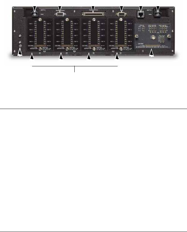
Figure 1-4 illustrates the location of the connectors, cards, and modules in the TimeProvider 1000.
28 TimeProvider User’s Guide |
097-58001-02 Revision G – April 2008 |

Chapter 1 Overview of the TimeProvider
Physical Description
Ethernet |
Remote Serial |
GPS |
Expansion |
Output Modules |
Power |
Connector |
Connector |
Connector |
Connector |
|
Connector |
|
|
|
|
|
|
|
|
|
|
|
|
|
|
|
|
|
|
|
|
|
|
|
|
|
|
|
|
|
|
|
|
|
|
|
|
|
|
|
|
|
|
|
|
|
|
|
|
|
|
|
|
|
|
|
|
|
|
|
|
|
|
|
|
|
|
|
|
|
|
|
|
|
|
|
|
|
|
|
|
|
|
|
|
|
|
|
|
|
|
|
|
|
|
|
|
|
|
|
|
|
|
|
|
|
|
|
|
|
|
|
|
|
|
|
|
|
|
|
|
|
|
|
|
|
|
|
|
|
|
|
|
|
|
|
|
|
|
|
|
|
|
|
|
|
|
|
|
|
|
|
|
|
|
|
|
|
|
|
|
|
|
|
|
|
|
|
|
|
|
|
|
|
|
|
|
|
|
|
|
|
|
|
|
|
|
|
|
|
|
|
|
|
|
|
|
|
|
|
|
|
|
|
|
|
|
|
|
|
|
|
|
|
|
|
|
|
|
|
|
|
|
|
|
|
|
|
|
|
|
|
|
|
|
|
|
|
|
|
|
|
|
|
|
|
|
|
|
|
|
|
|
|
|
|
|
|
|
|
|
|
|
|
|
|
|
|
|
|
|
Power |
IOC 1 |
Input |
|
|
IMC Local Craft |
|
IOC 2 |
|||||||||||||||||||
Connector |
Module |
|
|
|
|
|
Connector |
|
|
|
|
|
|
|
||||||||||||
|
|
|
|
|
Figure 1-4. |
Front Panel of the TimeProvider 1000 |
|
|
|
|
|
|
|
|||||||||||||
Figure 1-5 illustrates the location of the connectors, cards, and modules on the rear panel of the TimeProvider 1100. The chassis in Figure 1-5 is the older version that uses a 3-pin power connector.
Power |
Remote Serial |
Expansion |
GPS |
|
Ethernet |
|
Power |
|||||||||||||||||||||
Connector |
Connector |
Connector |
Connector |
|
Connector |
|
Connector |
|||||||||||||||||||||
|
|
|
|
|
|
|
|
|
|
|
|
|
|
|
|
|
|
|
|
|
|
|
|
|
|
|
|
|
|
|
|
|
|
|
|
|
|
|
|
|
|
|
|
|
|
|
|
|
|
|
|
|
|
|
|
|
|
|
|
|
|
|
|
|
|
|
|
|
|
|
|
|
|
|
|
|
|
|
|
|
|
|
|
|
|
|
|
|
|
|
|
|
|
|
|
|
|
|
|
|
|
|
|
|
|
|
|
|
|
|
|
|
|
|
|
|
|
|
|
|
|
|
|
|
|
|
|
|
|
|
|
|
|
|
|
|
|
|
|
|
|
|
|
|
|
|
|
|
|
|
|
|
|
|
|
|
|
|
|
|
|
|
|
|
|
|
|
|
|
|
|
|
|
|
|
|
|
|
|
|
|
|
|
|
|
|
|
|
|
|
|
|
|
|
|
|
|
|
|
|
|
|
|
Input |
Output Modules |
Module |
Figure 1-5. Rear Panel of the TimeProvider 1100 – Old Version
097-58001-02 Revision G – April 2008 |
TimeProvider User’s Guide 29 |
Chapter 1 Overview of the TimeProvider
Functional Description
Figure 1-6 illustrates the location of the connectors, cards, frame ground lugs, and modules on the rear panel of the TimeProvider 1100. The chassis in Figure 1-6 is the newer version that uses a terminal block for power connections.
|
Power |
Remote Serial |
Expansion |
GPS |
Ethernet |
|
|
|
Power |
||||||||||||||||||||||
Connector |
Connector |
Connector |
Connector |
Connector |
|
Connector |
|||||||||||||||||||||||||
|
|
|
|
|
|
|
|
|
|
|
|
|
|
|
|
|
|
|
|
|
|
|
|
|
|
|
|
|
|
|
|
|
|
|
|
|
|
|
|
|
|
|
|
|
|
|
|
|
|
|
|
|
|
|
|
|
|
|
|
|
|
|
|
|
|
|
|
|
|
|
|
|
|
|
|
|
|
|
|
|
|
|
|
|
|
|
|
|
|
|
|
|
|
|
|
|
|
|
|
|
|
|
|
|
|
|
|
|
|
|
|
|
|
|
|
|
|
|
|
|
|
|
|
|
|
|
|
|
|
|
|
|
|
|
|
|
|
|
|
|
|
|
|
|
|
|
|
|
|
|
|
|
|
|
|
|
|
|
|
|
|
|
|
|
|
|
|
|
|
|
|
|
|
|
|
|
|
|
|
|
|
|
|
|
|
|
|
|
|
|
|
|
|
|
|
|
|
|
|
|
|
|
|
|
|
|
|
|
|
|
|
|
|
|
|
|
|
|
|
|
|
|
|
|
|
|
|
|
|
|
|
|
|
|
|
|
|
|
|
|
|
|
|
|
|
|
|
|
|
|
|
|
|
|
|
|
|
|
|
|
|
|
|
|
|
|
|
|
|
|
|
|
|
|
|
|
|
|
|
|
|
|
|
|
|
|
|
Frame |
|
Input |
Ground Lugs |
Output Modules |
Module |
Figure 1-6. |
Rear Panel of the TimeProvider 1100 – New Version |
|
Functional Description
The TimeProvider consists of a main shelf and slots for two IOCs and one IMC. One plug-in Input module and up to four plug-in Output modules complete the main shelf, which provides up to 32 outputs. The optional Expansion Panel can provide up to 32 additional outputs, to provide a total of 64 outputs.
This section describes the components and block diagram of the TimeProvider. The block diagram, shown in Figure 1-7, contains the following major blocks:
Shelf
Input module
IMC or integrated IMC/TPIU
IOC
Output module
Expansion Panel required for ports 33 through 64
TimeProvider Interface Unit (TPIU)
30 TimeProvider User’s Guide |
097-58001-02 Revision G – April 2008 |
Loading...