


XLi IEEE 1588
Table of contents
 Loading...
XLi IEEE 1588 Clock
User Guide
997-01510-03, Rev. C, December 2006

Notices
Symmetricom, Inc.
Timing Test & Measurement
3750 Westwind Blvd.
Santa Rosa, CA 95403-1053
http://www.symmetricom.com
Copyright © 2006, Symmetricom, Inc.
All rights reserved. Printed in U.S.A.
All product names, service marks, trademarks, and registered trademarks
used in this document are the property of their respective owners.
The manual’s contents do not apply to previously released versions of XLi hardware or
software.

SSSSSSSSSSSS SSSSSSSSSS SSSSSSS S SSS S SSSSS S
Table of Contents
1: Overview and Features . . . . . . . . . . . . . . . . . . . . . . . . . . . . . . . .1
Overview . . . . . . . . . . . . . . . . . . . . . . . . . . . . . . . . . . . . . . . . . . . . . . .1
Description . . . . . . . . . . . . . . . . . . . . . . . . . . . . . . . . . . . . . . . . . . . .1
Standard Configuration . . . . . . . . . . . . . . . . . . . . . . . . . . . . . . . . . .1
1588-Related Specifications . . . . . . . . . . . . . . . . . . . . . . . . . . . . . . . . .2
IEEE 1588 card . . . . . . . . . . . . . . . . . . . . . . . . . . . . . . . . . . . . . . . .2
IEEE 1588 Subsystem . . . . . . . . . . . . . . . . . . . . . . . . . . . . . . . .2
Physical . . . . . . . . . . . . . . . . . . . . . . . . . . . . . . . . . . . . . . . . . . .2
Network Port (“1588”) . . . . . . . . . . . . . . . . . . . . . . . . . . . . . . . . .3
PPS Output (“SYNC OUT”) . . . . . . . . . . . . . . . . . . . . . . . . . . . .3
Behavior . . . . . . . . . . . . . . . . . . . . . . . . . . . . . . . . . . . . . . . . . . .3
User Interface . . . . . . . . . . . . . . . . . . . . . . . . . . . . . . . . . . . . . . .3
LEDs . . . . . . . . . . . . . . . . . . . . . . . . . . . . . . . . . . . . . . . . . . . . . .4
GPS C/A Receiver (87-8028-2) . . . . . . . . . . . . . . . . . . . . . . . . . . . .4
Introduction . . . . . . . . . . . . . . . . . . . . . . . . . . . . . . . . . . . . . . . . .4
Specifications . . . . . . . . . . . . . . . . . . . . . . . . . . . . . . . . . . . . . . .5
Standard TCVCXO Oscillator . . . . . . . . . . . . . . . . . . . . . . . . . . . . .5
Standard 110 VAC Power Supply . . . . . . . . . . . . . . . . . . . . . . . . . .6
Clock Architecture . . . . . . . . . . . . . . . . . . . . . . . . . . . . . . . . . . . . . . . .7
2
1
2: System Specifications . . . . . . . . . . . . . . . . . . . . . . . . . . . . . . . . .9
Mechanical/Environmental . . . . . . . . . . . . . . . . . . . . . . . . . . . . . . . . . .9
AC Power Supply . . . . . . . . . . . . . . . . . . . . . . . . . . . . . . . . . . . . . . . . .9
System Time & Frequency Accuracy . . . . . . . . . . . . . . . . . . . . . . . . .10
GPS Receiver . . . . . . . . . . . . . . . . . . . . . . . . . . . . . . . . . . . . . . . .10
Aux Ref Input . . . . . . . . . . . . . . . . . . . . . . . . . . . . . . . . . . . . . . . . .10
Chassis . . . . . . . . . . . . . . . . . . . . . . . . . . . . . . . . . . . . . . . . . . . . . . .10
Standard Inputs and Outputs . . . . . . . . . . . . . . . . . . . . . . . . . . . . . . .11
Serial I/O Port . . . . . . . . . . . . . . . . . . . . . . . . . . . . . . . . . . . . . . . .11
NET – Network Port . . . . . . . . . . . . . . . . . . . . . . . . . . . . . . . . . . . .11
J1 Input – Time Interval - Event Time . . . . . . . . . . . . . . . . . . . . . .12
J2 Output – Rate Out . . . . . . . . . . . . . . . . . . . . . . . . . . . . . . . . . . .12
J3 Input – Auxiliary Reference . . . . . . . . . . . . . . . . . . . . . . . . . . .13
1 PPS – Pulse Per Second Output . . . . . . . . . . . . . . . . . . . . . . . .13
CODE – Time Code Output . . . . . . . . . . . . . . . . . . . . . . . . . . . . . .13
ALARM Output . . . . . . . . . . . . . . . . . . . . . . . . . . . . . . . . . . . . . . .14
Certifications . . . . . . . . . . . . . . . . . . . . . . . . . . . . . . . . . . . . . . . . . . .14
3: Installation and Set-up . . . . . . . . . . . . . . . . . . . . . . . . . . . . . . .15
Installing the GPS Antenna . . . . . . . . . . . . . . . . . . . . . . . . . . . . . . . .15
Selecting a GPS Antenna Site . . . . . . . . . . . . . . . . . . . . . . . . . . . .15
Verifying the Site . . . . . . . . . . . . . . . . . . . . . . . . . . . . . . . . . . . . . .16
Mounting the GPS Antenna . . . . . . . . . . . . . . . . . . . . . . . . . . . . . .16
GPS Signal Strength Requirements . . . . . . . . . . . . . . . . . . . . . . .17
Making Additional Connections and Powering Up . . . . . . . . . . . . . . .18
Configuring Network Settings . . . . . . . . . . . . . . . . . . . . . . . . . . . . . . .19
Configuring the XLi . . . . . . . . . . . . . . . . . . . . . . . . . . . . . . . . . . . . . . .19
5
XLi IEEE 1588 Clock iii
997-01510-03, Rev. C, 12/12/2006

SSSSSSSSSSSS SSSSSSSSSS SSSSSSS S SSS S SSSSS S
Configuring the IEEE 1588 Card(s) . . . . . . . . . . . . . . . . . . . . . . . . . 20
PTP Master . . . . . . . . . . . . . . . . . . . . . . . . . . . . . . . . . . . . . . . . . 20
PTP Slave . . . . . . . . . . . . . . . . . . . . . . . . . . . . . . . . . . . . . . . . . . 21
Rack Mounting the XLi . . . . . . . . . . . . . . . . . . . . . . . . . . . . . . . . . . . 22
1
4: User Interfaces . . . . . . . . . . . . . . . . . . . . . . . . . . . . . . . . . . . . .25
Alarm Status LED . . . . . . . . . . . . . . . . . . . . . . . . . . . . . . . . . . . . . . . 25
Keypad/Display Interface . . . . . . . . . . . . . . . . . . . . . . . . . . . . . . . . . 25
Time Display . . . . . . . . . . . . . . . . . . . . . . . . . . . . . . . . . . . . . . . . . 25
Status Display . . . . . . . . . . . . . . . . . . . . . . . . . . . . . . . . . . . . . . . . 26
Menu Display . . . . . . . . . . . . . . . . . . . . . . . . . . . . . . . . . . . . . . . . 26
Keypad Operation . . . . . . . . . . . . . . . . . . . . . . . . . . . . . . . . . . . . 27
Keypad Examples . . . . . . . . . . . . . . . . . . . . . . . . . . . . . . . . . . . . 28
Command Line Interface . . . . . . . . . . . . . . . . . . . . . . . . . . . . . . . . . . 29
Logging In . . . . . . . . . . . . . . . . . . . . . . . . . . . . . . . . . . . . . . . . . . . 29
Operator Login . . . . . . . . . . . . . . . . . . . . . . . . . . . . . . . . . . . . . 29
Guest Login . . . . . . . . . . . . . . . . . . . . . . . . . . . . . . . . . . . . . . . 29
Logging Out . . . . . . . . . . . . . . . . . . . . . . . . . . . . . . . . . . . . . . . . . 30
Changing Username and Password . . . . . . . . . . . . . . . . . . . . . . . 30
Session Timeout and Priority . . . . . . . . . . . . . . . . . . . . . . . . . . . . 30
Web Interface . . . . . . . . . . . . . . . . . . . . . . . . . . . . . . . . . . . . . . . . . . 31
User Privileges . . . . . . . . . . . . . . . . . . . . . . . . . . . . . . . . . . . . . . . 31
Sessions . . . . . . . . . . . . . . . . . . . . . . . . . . . . . . . . . . . . . . . . . . . . 32
User Names and Passwords . . . . . . . . . . . . . . . . . . . . . . . . . . . . 32
Logging In . . . . . . . . . . . . . . . . . . . . . . . . . . . . . . . . . . . . . . . . . . . 32
Navigating . . . . . . . . . . . . . . . . . . . . . . . . . . . . . . . . . . . . . . . . . . 32
Submitting Changes . . . . . . . . . . . . . . . . . . . . . . . . . . . . . . . . . . . 33
Logging Out . . . . . . . . . . . . . . . . . . . . . . . . . . . . . . . . . . . . . . . . . 33
Notes . . . . . . . . . . . . . . . . . . . . . . . . . . . . . . . . . . . . . . . . . . . . . . 33
5: Function Reference . . . . . . . . . . . . . . . . . . . . . . . . . . . . . . . . . .35
Function Summary . . . . . . . . . . . . . . . . . . . . . . . . . . . . . . . . . . . . . . 35
F1 – Time Zone Offset . . . . . . . . . . . . . . . . . . . . . . . . . . . . . . . . . . . 38
F2 – 12/24 Hour Format . . . . . . . . . . . . . . . . . . . . . . . . . . . . . . . . . . 39
F3 – Time & Date . . . . . . . . . . . . . . . . . . . . . . . . . . . . . . . . . . . . . . . 40
F4 – Serial Port Configuration . . . . . . . . . . . . . . . . . . . . . . . . . . . . . . 42
F5 – Time-Quality Setup . . . . . . . . . . . . . . . . . . . . . . . . . . . . . . . . . . 43
F6 – Keypad Lock . . . . . . . . . . . . . . . . . . . . . . . . . . . . . . . . . . . . . . . 45
F8 - Continuous Time Once-per-Second . . . . . . . . . . . . . . . . . . . . . 46
The Format of the F8 Output String . . . . . . . . . . . . . . . . . . . . . . . 47
While Synchronizing to a Reference Source . . . . . . . . . . . . . . . . 48
After Loosing a Reference Source . . . . . . . . . . . . . . . . . . . . . . . . 48
F9 - Time On Request . . . . . . . . . . . . . . . . . . . . . . . . . . . . . . . . . . . . 49
F11 - Time Output Format . . . . . . . . . . . . . . . . . . . . . . . . . . . . . . . . . 50
F13 – Time Error . . . . . . . . . . . . . . . . . . . . . . . . . . . . . . . . . . . . . . . . 52
F18 – Software Version Request . . . . . . . . . . . . . . . . . . . . . . . . . . . 53
F27 – FTM III Configuration . . . . . . . . . . . . . . . . . . . . . . . . . . . . . . . 53
F42 – Multicode Output Configuration . . . . . . . . . . . . . . . . . . . . . . . 53
F44 – N.8 Frequency Synthesizer . . . . . . . . . . . . . . . . . . . . . . . . . . 53
F50 – GPS Receiver LLA/XYZ Position . . . . . . . . . . . . . . . . . . . . . . 53
iv XLi IEEE 1588 Clock
997-01510-03, Rev. C, 12/12/2006

SSSSSSSSSSSS SSSSSSSSSS SSSSSSS S SSS S SSSSS S
F51 – GPS Antenna Cable Delay . . . . . . . . . . . . . . . . . . . . . . . . . . .55
F52 – Distribution Cable Delay . . . . . . . . . . . . . . . . . . . . . . . . . . . . .57
F53 – GPS Operation Mode . . . . . . . . . . . . . . . . . . . . . . . . . . . . . . . .58
F60 – GPS Receiver Satellite List . . . . . . . . . . . . . . . . . . . . . . . . . . .60
F66 – Daylight Saving Time (DST) Mode . . . . . . . . . . . . . . . . . . . . . .63
F69 – Time Mode . . . . . . . . . . . . . . . . . . . . . . . . . . . . . . . . . . . . . . . .65
F71 – Oscillator Statistics . . . . . . . . . . . . . . . . . . . . . . . . . . . . . . . . . .67
F72 – Fault Status . . . . . . . . . . . . . . . . . . . . . . . . . . . . . . . . . . . . . . .68
F73 – Alarm Control / Status . . . . . . . . . . . . . . . . . . . . . . . . . . . . . . .69
F74 – Clock Source Control . . . . . . . . . . . . . . . . . . . . . . . . . . . . . . . .77
F90 – Code Output Configuration . . . . . . . . . . . . . . . . . . . . . . . . . . .78
F100 – Network Port Configuration & XLi Firmware . . . . . . . . . . . . .80
F100 EA – Ethernet Address . . . . . . . . . . . . . . . . . . . . . . . . . . . . .82
F100 IP – IP Address . . . . . . . . . . . . . . . . . . . . . . . . . . . . . . . . . .82
F100 SM – Subnet Mask . . . . . . . . . . . . . . . . . . . . . . . . . . . . . . . .83
F100 G – Gateway . . . . . . . . . . . . . . . . . . . . . . . . . . . . . . . . . . . .84
F100 IC – Network Port Settings . . . . . . . . . . . . . . . . . . . . . . . . . .85
F100 BASET – 10/100 BASE- T . . . . . . . . . . . . . . . . . . . . . . . . . .85
F100 L/LOCK/UNLOCK – Remote Lockout . . . . . . . . . . . . . . . . .86
F100 L – Remote Lockout . . . . . . . . . . . . . . . . . . . . . . . . . . . . . . .87
F100 ST – Self Test Status . . . . . . . . . . . . . . . . . . . . . . . . . . . . . .88
F100 BH – Burn Host . . . . . . . . . . . . . . . . . . . . . . . . . . . . . . . . . .89
F100 BUB – Burn BootLoader . . . . . . . . . . . . . . . . . . . . . . . . . . . .89
F100 BU – Burn . . . . . . . . . . . . . . . . . . . . . . . . . . . . . . . . . . . . . . .90
F100 BF – Burn File System . . . . . . . . . . . . . . . . . . . . . . . . . . . . .91
F100 BUFP – Burn FPGA Firmware . . . . . . . . . . . . . . . . . . . . . . .91
F100 CONFIG – Configure NTP & SNMP . . . . . . . . . . . . . . . . . . .92
F100 J – Factory Mode Jumper . . . . . . . . . . . . . . . . . . . . . . . . . . .93
F100 K I L L – Reboot . . . . . . . . . . . . . . . . . . . . . . . . . . . . . . . . . .94
F100 P – Change User Password . . . . . . . . . . . . . . . . . . . . . . . . .95
F100 PI – PING . . . . . . . . . . . . . . . . . . . . . . . . . . . . . . . . . . . . . . .96
F100 PN – Change User Name . . . . . . . . . . . . . . . . . . . . . . . . . . .97
F108 – Oscillator Configuration . . . . . . . . . . . . . . . . . . . . . . . . . . . . .98
F110 – J1 Input (TIET) . . . . . . . . . . . . . . . . . . . . . . . . . . . . . . . . . . . .99
F111 – J2 Output (Rate) . . . . . . . . . . . . . . . . . . . . . . . . . . . . . . . . . .102
F113 – J3 Input Configuration (Aux Ref) . . . . . . . . . . . . . . . . . . . . .104
F116 – Display Brightness Level . . . . . . . . . . . . . . . . . . . . . . . . . . .106
F117 – Factory Configuration . . . . . . . . . . . . . . . . . . . . . . . . . . . . . .107
F118 – Option Board Configuration . . . . . . . . . . . . . . . . . . . . . . . . .108
F119 – GPS Receiver Configuration . . . . . . . . . . . . . . . . . . . . . . . .110
F120 - N.1 Frequency Synthesizer . . . . . . . . . . . . . . . . . . . . . . . . .114
F123 – Have Quick Input/1 PPS Sync Configuration . . . . . . . . . . . . 114
F126 – Options Key Entry . . . . . . . . . . . . . . . . . . . . . . . . . . . . . . . .115
F128 – Have Quick Output . . . . . . . . . . . . . . . . . . . . . . . . . . . . . . . .115
F130 - Precision Time Protocol Status . . . . . . . . . . . . . . . . . . . . . . . 116
F131 - Precision Time Protocol Network Config . . . . . . . . . . . . . . . 119
Option bay location of the IEEE 1588 cards . . . . . . . . . . . . . . . . 119
Static IP address, subnet mask and default gateway for the network port 119
DHCP enabled/disabled . . . . . . . . . . . . . . . . . . . . . . . . . . . . . . .120
DHCP-assigned IP address, subnet mask and default gateway for the network port 120
2
1
5
XLi IEEE 1588 Clock v
997-01510-03, Rev. C, 12/12/2006

SSSSSSSSSSSS SSSSSSSSSS SSSSSSS S SSS S SSSSS S
PTP Sync message interval . . . . . . . . . . . . . . . . . . . . . . . . . . . . 120
PTP burst mode enabled/disabled . . . . . . . . . . . . . . . . . . . . . . . 121
PTP network port enabled/disabled . . . . . . . . . . . . . . . . . . . . . . 121
PTP subdomain same . . . . . . . . . . . . . . . . . . . . . . . . . . . . . . . . 121
1
Reset PTP settings to factory defaults . . . . . . . . . . . . . . . . . . . . 121
PTP initialize to user entered values . . . . . . . . . . . . . . . . . . . . . 121
PTP Master or Slave (PRI/SEC/STBY) . . . . . . . . . . . . . . . . . . . 122
PTP Slave Synchronization Threshold . . . . . . . . . . . . . . . . . . . . 122
PTP Preferred Master Configuration . . . . . . . . . . . . . . . . . . . . . 122
Request a summary of the PTP card configuration . . . . . . . . . . 125
Set Internet Configuration settings . . . . . . . . . . . . . . . . . . . . . . . 125
Set the IP Address . . . . . . . . . . . . . . . . . . . . . . . . . . . . . . . . . . . 126
Set the Subnet Mask . . . . . . . . . . . . . . . . . . . . . . . . . . . . . . . . . 126
Set the Default Gateway . . . . . . . . . . . . . . . . . . . . . . . . . . . . . . 127
Setting the Internet Configuration . . . . . . . . . . . . . . . . . . . . . . . . 128
Enable/Disable DHCP . . . . . . . . . . . . . . . . . . . . . . . . . . . . . . . . 128
Get PTP Protocol settings . . . . . . . . . . . . . . . . . . . . . . . . . . . . . 129
Request the PTP Subdomain Name . . . . . . . . . . . . . . . . . . . . . 130
Set the PTP Subdomain Name . . . . . . . . . . . . . . . . . . . . . . . . . 130
Reset the PTP Parameters to the Factory Default settings . . . . 131
Initialize the PTP Protocol to User-entered Values . . . . . . . . . . 131
Configuring the PTP Reference Clock Settings . . . . . . . . . . . . . 132
Request the PTP Slave Synchronization Threshold . . . . . . . . . 133
Set the PTP Slave Synchronization Threshold . . . . . . . . . . . . . 133
Request the PTP Preferred Master Clock Configuration . . . . . . 134
Enable or Disable the PTP Preferred Master Clock Configuration 134
F131 B<N> S<CR> REQUEST PTP NETWORK PARAMETERS STATUS 134
9: XLi-Generated Messages 137
Error Messages . . . . . . . . . . . . . . . . . . . . . . . . . . . . . . . . . . . . . . . . 137
Informational Messages . . . . . . . . . . . . . . . . . . . . . . . . . . . . . . . . . 139
A: Using F100 Configuration 141
Configuring SNMP Parameters . . . . . . . . . . . . . . . . . . . . . . . . . . . . 141
Overview of Steps . . . . . . . . . . . . . . . . . . . . . . . . . . . . . . . . . . . 141
Set up the FTP Server . . . . . . . . . . . . . . . . . . . . . . . . . . . . . . . . 141
Get the IP Address of the FTP Server/Workstation . . . . . . . . . . 141
Copy the Configuration Files to the FTP Server . . . . . . . . . . . . . 142
Edit the Configuration Files . . . . . . . . . . . . . . . . . . . . . . . . . . . . 142
Move the Configuration Files Back to the XLi . . . . . . . . . . . . . . 143
B: Upgrading System Firmware 145
Overview of Procedure . . . . . . . . . . . . . . . . . . . . . . . . . . . . . . . . 145
Set up the FTP Server . . . . . . . . . . . . . . . . . . . . . . . . . . . . . . . . 145
Open a Command Line Session on the XLi . . . . . . . . . . . . . . . . 145
Upgrade the Firmware . . . . . . . . . . . . . . . . . . . . . . . . . . . . . . . . 146
Troubleshooting . . . . . . . . . . . . . . . . . . . . . . . . . . . . . . . . . . . . . 148
FAQ . . . . . . . . . . . . . . . . . . . . . . . . . . . . . . . . . . . . . . . . . . . . . . 149
vi XLi IEEE 1588 Clock
997-01510-03, Rev. C, 12/12/2006

SSSSSSSSSSSS SSSSSSSSSS SSSSSSS S SSS S SSSSS S
C: SNMP 151
SymmetricomTtm-SMIv2.mib . . . . . . . . . . . . . . . . . . . . . . . . . . . . . .151
xliMainCard-SMIv2.mib . . . . . . . . . . . . . . . . . . . . . . . . . . . . . . . . . .161
xli-SMIv2.mib . . . . . . . . . . . . . . . . . . . . . . . . . . . . . . . . . . . . . . . . . .165
xliSystem-SMIv2.mib . . . . . . . . . . . . . . . . . . . . . . . . . . . . . . . . . . . .165
Editing snmp.conf . . . . . . . . . . . . . . . . . . . . . . . . . . . . . . . . . . . . . . .176
SNMP Private Enterprise MIB Structure . . . . . . . . . . . . . . . . . . . . .177
SNMP Addressing . . . . . . . . . . . . . . . . . . . . . . . . . . . . . . . . . . . .177
New Top Level Structure of Enterprise MIB for XLi . . . . . . . . . . .177
XLi System Group . . . . . . . . . . . . . . . . . . . . . . . . . . . . . . . . . .179
The XLi Fault Group . . . . . . . . . . . . . . . . . . . . . . . . . . . . . . . .180
The XLi System Status Group . . . . . . . . . . . . . . . . . . . . . . . .181
XLi MainCard Group . . . . . . . . . . . . . . . . . . . . . . . . . . . . . . . .182
XLi Traps . . . . . . . . . . . . . . . . . . . . . . . . . . . . . . . . . . . . . . . . . . .182
Future Expansion . . . . . . . . . . . . . . . . . . . . . . . . . . . . . . . . . . . .182
Glossary of SNMP-Related Terms . . . . . . . . . . . . . . . . . . . . . . . .183
Configuring and Testing SNMP . . . . . . . . . . . . . . . . . . . . . . . . . . . .184
Materials Needed . . . . . . . . . . . . . . . . . . . . . . . . . . . . . . . . . . . .184
HP OpenView Configuration . . . . . . . . . . . . . . . . . . . . . . . . . . . .184
XLi Configuration . . . . . . . . . . . . . . . . . . . . . . . . . . . . . . . . . . . . .186
Test Procedure . . . . . . . . . . . . . . . . . . . . . . . . . . . . . . . . . . . . . .186
2
1
E: Time Code Formats 189
Overview . . . . . . . . . . . . . . . . . . . . . . . . . . . . . . . . . . . . . . . . . . . . .189
IRIG . . . . . . . . . . . . . . . . . . . . . . . . . . . . . . . . . . . . . . . . . . . . . . . . .189
Introduction . . . . . . . . . . . . . . . . . . . . . . . . . . . . . . . . . . . . . . . . .189
IRIG Code Format . . . . . . . . . . . . . . . . . . . . . . . . . . . . . . . . . . . .189
IRIG-B Time Quality Flags . . . . . . . . . . . . . . . . . . . . . . . . . . . . . .190
Output . . . . . . . . . . . . . . . . . . . . . . . . . . . . . . . . . . . . . . . . . . .190
Input . . . . . . . . . . . . . . . . . . . . . . . . . . . . . . . . . . . . . . . . . . . .190
NASA 36 . . . . . . . . . . . . . . . . . . . . . . . . . . . . . . . . . . . . . . . . . . . . .190
Introduction . . . . . . . . . . . . . . . . . . . . . . . . . . . . . . . . . . . . . . . . .190
NASA 36 Code Format . . . . . . . . . . . . . . . . . . . . . . . . . . . . . . . .191
Output . . . . . . . . . . . . . . . . . . . . . . . . . . . . . . . . . . . . . . . . . . .191
Input . . . . . . . . . . . . . . . . . . . . . . . . . . . . . . . . . . . . . . . . . . . .191
F: World Map of Time Zones: 193
G: Part Numbers 195
H: Sales and Customer Assistance 197
Glossary of IEEE 1588-related Terms 199
Index 201
5
XLi IEEE 1588 Clock vii
997-01510-03, Rev. C, 12/12/2006

SSSSSSSSSSSS SSSSSSSSSS SSSSSSS S SSS S SSSSS S
1
viii XLi IEEE 1588 Clock
997-01510-03, Rev. C, 12/12/2006

SSSSSSSSSSSS SSSSSSSSSS SSSSSSS S SSS S SSSSS S
1: Overview and Features
Overview
Description
The standard XLi IEEE 1588 Clock, also referred to as the “XLi”, provides a complete implement ation of
a Precise Time Protocol (PTP) “ordinary clock” over a dedicated IEEE 1588 card. The IEEE 1588 card
can be configured to operate as a PTP grandmaster or as a PTP slave.
As a PTP grandmaster, the IEEE 1588 card typically synchronizes PTP slaves on the network to
International Atomic Time (TAI). The XLi IEEE 1588 Clock derives TAI from the Global Positioning
System (GPS). In addition, Symmetricom designed the XLi IEEE 1588 Clock so the user can distribute
Coordinated Universal Time (UTC) or user-entered time over PTP.
2
1
As a PTP slave, the IEEE card automatically discovers a PTP master within its subnet/subdomain and
synchronizes to it. The PTP slave in turn, can be configured as the primary reference source for the XLi
IEEE 1588 Clock (the clock synchronizes to the PTP slave).
The XLi’s Time Interval/Event Time (TIET) feature can be used to measure PTP synchronization across
timing networks. For example, to measure a PTP slave’s synchronization to the PTP grandmaster, the
user connects the PPS output of a PTP slave to the XLi IEEE 1588 Clock and configures F110 to display
the time interval between each PPS.
See F130 - Precision Time Protocol Status
Config (page 119) for more information.
Standard Configuration
(page 116) and F131 - Precision Time Protocol Network
The XLi IEEE 1588 Clock can be purchased in two configurations. The first configuration includes one
IEEE 1588 card preconfigured as a PTP master and located in Option Bay 4. The second configuration
has an additional IEEE 1588 card preconfigured as a PTP slave located in Option Bay 2. Both
configurations include the following items.
• XLi chassis and CPU card running special firmware
• The IEEE 1588 card(s)
• GPS C/A Receiver (87-8028-2)
• L1 GPS Antenna
• GPS antenna cable: 50 ft. (15.24 m) of RG-59
• Time Interval Event Time (TIET)
• Standard 110 VAC Power Supply
• Standard TCVCXO Oscillator
1. Other GPS antenna cable lengths can be specified at the time of purchase.
XLi IEEE 1588 Clock 1
997-01510-03, Rev. C, 12/12/2006
1
5

SSSSSSSSSSSS SSSSSSSSSS SSSSSSS S SSS S SSSSS S
Only the features listed above are supported for the XLi IEEE 1588 clock. At the time of this writing, none
of the other options for the XLi Time and Frequency system are supported on the XLi IEEE 1588 clock.
Contact Symmetricom Sales to obtain a special supported configuration of the XLi IEEE 1588 clock. For
contact information, please see Sales and Customer Assistance (page 197).
1
1588-Related Specifications
The specifications in this section cover options included as standard features in the XLi IEEE 1588
Clock. See also “2: System Specifications” on page 9.
IEEE 1588 card
IEEE 1588 Subsystem
Compliance: IEEE 1588-2002
While operating as Grandmaster:
• Time stamp accuracy is equivalent to XLi clock accuracy: Please consult the datasheet online.
• Sync Intervals: 1, 2, 8, 16, and 64 seconds
• Packet throughput: >100 Delay_Req/second
• Delay_Req buffer: 256 time stamps
1
While operating as a Slave:
• Sync accuracy to master via crossover cable: Please consult datasheet online.
• Sync Interval: 2 seconds
Physical
Size: One option bay (1.9 cm h x 10.5 cm w x 17.4 d)
Connectors: One network port (RJ-45), labelled “1588”
One PPS output (BNC), labelled “SYNC OUT”
LEDs See “LEDs”, page 4.
1. http://www.symmttm.com/pdf/gps/DS_XLi1588.pdf
2 XLi IEEE 1588 Clock
997-01510-03, Rev. C, 12/12/2006

SSSSSSSSSSSS SSSSSSSSSS SSSSSSS S SSS S SSSSS S
Network Port (“1588”)
A IEEE1588-compliant “ordinary clock” is available from a stand-alone Ethernet port, labelled “1588”, on
the rear panel of the IEEE 1588 card.
Type: Standard RJ-45 8-pin connector, 100 Base-T
Qty: 1
Packet type
Protocols
Ethernet DIX II (RFC 894)
IPV4, IEEE1588, 802.3, ARP, and PING
2
PPS Output (“SYNC OUT”)
A raw unfiltered PPS output is available from the stand-alone BNC connector, labelled “SYNC OUT”, on
the rear panel of the IEEE 1588 card.
The PPS Output from the IEEE 1588 card while configured as a PTP master:
• 50% duty-cycle, +/-10% typical
• Please consult the datasheet online for additional specifications.
Behavior
The IEEE 1588 card can function as:
• PTP Grandmaster
- Best Master
- Preferred Master
• PTP Slave
- Primary Reference
- Secondary Reference
- Standby
1
1
5
User Interface
All of the IEEE 1588 card’s functions can be managed using the Web Interface (page 31), Command
Line Interface (page 29), or Keypad/Display Interface (page 25).
The following 1588-related functions are available from the command and keypad/display interfaces:
• F130 - Precision Time Protocol Status
• F131 - Precision Time Protocol Network Config
1. http://www.symmttm.com/pdf/gps/DS_XLi1588.pdf
XLi IEEE 1588 Clock 3
997-01510-03, Rev. C, 12/12/2006
(page 116)
(page 119)

SSSSSSSSSSSS SSSSSSSSSS SSSSSSS S SSS S SSSSS S
LEDs
The following LEDs are available on the IEEE 1588 card rear panel:
1
• Network Port (1588), Green and Amber LEDs illuminate when receiving or transmitting network
traffic.
• PPS: LED illuminates (green) while the SYNC OUT signal is high. See “PPS Output (“SYNC
OUT”)” on page 3.
• TX: LED illuminates (green) with transmission of a PTP packet.
• RX: LED illuminates (green) with arrival of a PTP packet.
• M/S: 1588 port operating as PTP master or slave:
- Green: PTP master.
- Amber: PTP slave.
ENA: Indicates the state of the 1588 port whether the 1588 software is running:
• Green: 1588 port is enabled, and the 1588 software is running.
• Amber: 1588 port is disabled, and the 1588 software is running.
• Red: The state of the 1588 port is unknown, and the 1588 software is not running.
See “F131 - Precision Time Protocol Network Config” on page 119.
GPS C/A Receiver (87-8028-2)
Introduction
The GPS C/A Receiver acts as a S tratum 0 timing reference source to the XLi. It tr acks up to 12 L1 GPS
satellites, decodes their signals for time and position, and feeds this data to the XLi through the internal
backplane. When available and enabled, the GPS C/A Receiver card provides superior time and
frequency accuracy on the XLi (See “
Receiver card comes with an L1 GPS antenna, cabling, and mounting hardware unless otherwise
specified at the time of purchase.
The GPS C/A Receiver uses a TRAIM (Time Receiver Autonomous Integrity Monitoring) algorithm to
monitor the integrity of the receiver’s timing solution. Using redundant measurements, TRAIM detects
and quarantines anomalous GPS signals, independent of the GPS health ephemeris data. The
quarantined signal is excluded from the timing solution for 12 hours before it is requalified for inclusion in
the timing solution.
See “
Installing the GPS Antenna” on page 15 for information on selecting an antenna site, mounting the
antenna, and signal strength requirements.
The GPS C/A Receiver card can be managed and configured using F53 – GPS Operation
Mode (page 58) and F119 – GPS Receiver Configuration (page 110).
System Time & Frequency Accuracy” on page 10). The GPS C/A
4 XLi IEEE 1588 Clock
997-01510-03, Rev. C, 12/12/2006

SSSSSSSSSSSS SSSSSSSSSS SSSSSSS S SSS S SSSSS S
Specifications
Frequency 1575.42 MHz (L1 signal)
Code Coarse Acquisition (C/A) code
Tracking Up to 12 satellites with TRAIM
Position Accuracy Typically < 10m when tracking four (4) satellites
TRAIM Mask 1 μS
1 PPS Accuracy UTC-USNO ±30 ns RMS 100 ns Peak
Time standard: UTC or GPS
Antenna input Female BNC
Antenna Power 20 mA – 220 mA, +12 V
Related topics:
Installing the GPS Antenna” on page 15
• “
• “F50 – GPS Receiver LLA/XYZ Position” on page 53
• “F51 – GPS Antenna Cable Delay” on page 55
• “F53 – GPS Operation Mode” on page 58
• “F60 – GPS Receiver Satellite List” on page 60
• “F69 – Time Mode” on page 65
• “F73 – Alarm Control / Status” on page 69
• “F74 – Clock Source Control” on page 77
• “F119 – GPS Receiver Configuration” on page 110
Standard TCVCXO Oscillator
Frequency/Timing Allan Deviation,
Stability
Temp
Drift Rate
-9
1 x 10
2 x 10
3 x 10
5x10
5 x 10
@ 1 sec
-10
@ 1K sec
-12
@ 1 day
-7
, over 0°C to 50°C when not locked to a reference
-9
/ Day
2
1
5
The XLi comes with the standard TCVCXO oscillator described below. The stability of the following
oscillators is dependent on the reference source. For reference source accuracies, see “
System Time &
Frequency Accuracy” on page 10 .
XLi IEEE 1588 Clock 5
997-01510-03, Rev. C, 12/12/2006

SSSSSSSSSSSS SSSSSSSSSS SSSSSSS S SSS S SSSSS S
Standard 110 VAC Power Supply
The XLi’s internal fault detector can monitor the three output voltages from the primary and the
secondary power supplies. With the Primary Power or Secondary Power indicators in F73 enabled, a
10% decrease in any of the output voltages triggers an alarm. See “
1
page 69.
Warning: Ensure that a disconnect device, such as a switch, with the appropriate volt age/current ra ting,
is provided when operating/installing the XLi.
Warning: Prior to servicing the interior of a unit with dual power supplies, remove both power cords.
Input connector: IEC 320 type
Input voltage range: Universal, 90 – 260 VAC and 110 – 370 VDC
Input frequency range: 47 Hz – 440 Hz
Isolation, ground: For 110-370 VDC operation, the input is fully floating. Either
input polarity may be strapped to chassis ground.
Isolation: 1,500 VAC, input to ground
Output Specifications: +5.2 V (5.0 to 5.4 V), 25 watts, 0 to 5 amps
+12 V (11.4 to 12.6 V), 45 watts, 0 to 3.8 amps
-12 V (–11.4 to –12.6 V) 32 watts, 0 to 2.7 amps
F73 – Alarm Control / Status” on
Fan: Exhaust 3-6CFM
6 XLi IEEE 1588 Clock
997-01510-03, Rev. C, 12/12/2006
SSSSSSSSSSSS SSSSSSSSSS SSSSSSS S SSS S SSSSS S
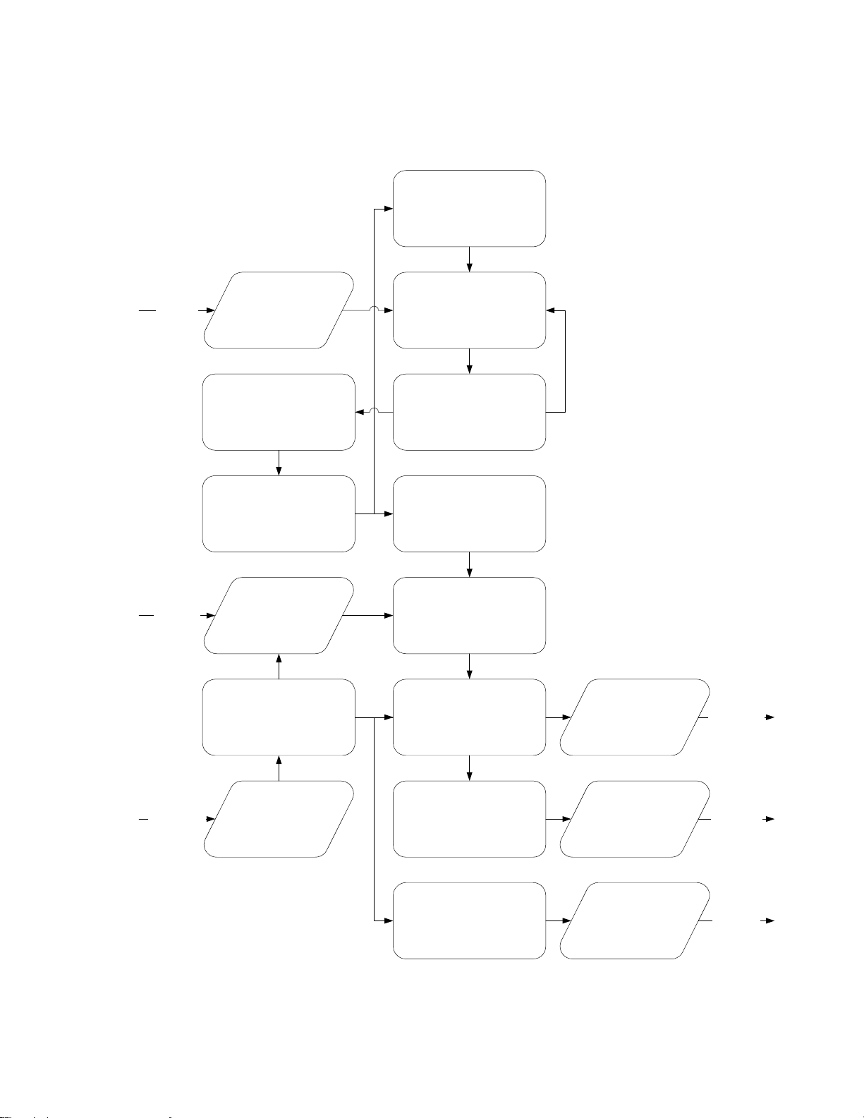
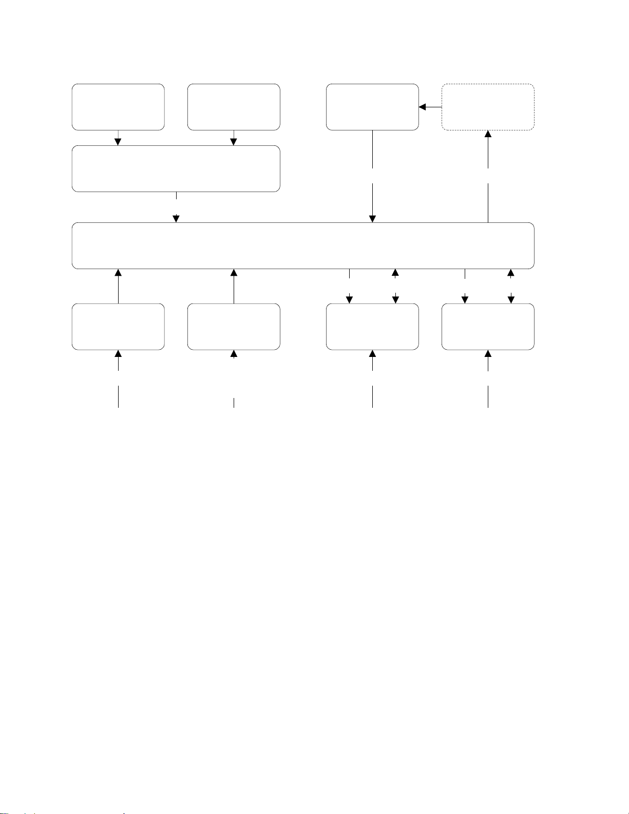
Clock Architecture
Figures 1 and 2 on the following pages provide a simplified view of the standard XL i's clock a rchitectu re.
16.384 MHz Osc. PLL
2
Aux Ref
Aux Ref
1,5,10 MHz
Phase Measurement
1 PPS A
1PPS B
Code Input
DAC
10 MHz Osc.
1 PPS
Timing
Select
Time and Clock
Recovery
Code Input
Clock DPLL
200 MHz PLL
Phase Compare
Clock Machine
Code Generation
1 PPS
Output
Code Out
1
5
1 PPS Out
Code Out
Rate Gen
Rate Out
Rate Out
Figure 1: Functional Timing Block Diagram
XLi IEEE 1588 Clock 7
997-01510-03, Rev. C, 12/12/2006
SSSSSSSSSSSS SSSSSSSSSS SSSSSSS S SSS S SSSSS S
1
Display Rb Power
Display/Keypad Interf ace
I/O
Power Supply AC
+5 V, +/- 12 V
110/220 AC
Keypad Oscillator
Backplane Interface
Power
Power Supply
DC +5 V, +/- 12 V
9-18 VDC
18-36 VDC
36-72 VDC
10 MHz
Option
User I/O
I/O
Power
Power, Vc
I/O
T&F CPU
User I/O
Figure 2: Interface Architecture Block Diagram
8 XLi IEEE 1588 Clock
997-01510-03, Rev. C, 12/12/2006

SSSSSSSSSSSS SSSSSSSSSS SSSSSSS S SSS S SSSSS S
2: System Specifications
Mechanical/Environmental
Power: 95-260 VAC, 47 to 440 Hz
Operating Temperature: 0 °C to +50 °C (+32 °F to +122 °F)
Maximum Rate of Change: 8 °C per hour
Storage Temperature: -55 °C to +85 °C (-67 °F to +185 °F)
Humidity: To 95% non-condensing
Operating Altitude: Maximum 4 km (2.49 mi. or 13147 ft.)
Front Panel Display: Vacuum Fluorescent Display (VFD) 4.38” x 0.88" (11.13cm x 2.24 cm). 160X16
pixels. Displays startup messages, clock status, time and day of year, and
interactive clock functions. TIME mode displays Time and Day of Y ea r (T OD) on
one full-height line.
Keypad: 0–9, UP, DOWN, LEFT, RIGHT, ENTER, CLR, TIME, STATUS, MENU
Serial I/O: Full user-selectable RS-232/422 communication protocol up to 19200 baud
Vibration Operating: GR-CORE-63, 4.5.2/4, locked to 1.0 g
Storage Transport: GR-CORE-63.4.4.1 to 1.5g
2
1
AC Power Supply
Input:
Input connector: IEC 320 connector
5
Input voltage range: Universal, 90 – 260 VAC and 110 – 370 VDC
Input freq. range: 47 Hz – 440 Hz
Output: +5.2 V (5.0 to 5.4 V), 25 watts, 0 to 5 amps
+12 V (11.4 to 12.6 V), 45 watts, 0 to 3.8 amps
-12 V (-11.4 to -12.6 V) 32 watts, 0 to 2.7 amps
Wattage: 104 watts
Power Supply Status: The Fault Detector monitors all three output voltages and provides a visual
(panel LED) and fault status if any output voltag e decreases by 10%.
Alarm Status LED: Green LED on with no fault and AC power applied. Green LED of f with fault or no
AC power applied.
Fan: Exhaust 3-6 CFM
XLi IEEE 1588 Clock 9
997-01510-03, Rev. C, 12/12/2006

SSSSSSSSSSSS SSSSSSSSSS SSSSSSS S SSS S SSSSS S
System Time & Frequency Accuracy
The tables below describe system clock accuracy while locked to the reference source indicated.
Currently, GPS is the only supported reference source.
1
GPS Receiver
1 PPS Output: ±30 ns RMS, 100 ns peak without SA (99%)
Frequency Output Accuracy:
Frequency/Timing, Allan
Deviation, Stability:
< 2x 10
1 x 10
2 x 10
1x 10
-12
-9
@ 1 sec
-10
@ 1000 sec
-12
@ 1 day
AM Code Output Accuracy: 10
DC Level Shift Code Output
Accuracy:
Time to System Lock <20 min. typical
μS to the 1 PPS
200 ns to the 1 PPS
See GPS Signal Strength Requirements (page 17) and GPS C/A Receiver (87-8028-2) (page 4).
Aux Ref Input
If an Aux Ref input is available and enabled, the XLi assumes that Aux Ref is a better frequency source
than its own oscillator. If a timing reference is not available (or becomes unavailable) and Aux Ref is
enabled, the XLi locks to the Aux Ref input. Under those conditions, frequency output accuracy is equal
to the reference < 1 x 10
-12.
Note: To set the time and date manually, see “F3 – Time & Date” on page 40.
Chassis
1U Chassis: Standard 19" EIA Rack System, hardware included
Receiver Size: 1.75 in. x 17.1 in. x 15.35 in.
Weight: Standard configuration, without options ~9.25 lb. Fully loaded ~ 10.95 lb
10 XLi IEEE 1588 Clock
997-01510-03, Rev. C, 12/12/2006

SSSSSSSSSSSS SSSSSSSSSS SSSSSSS S SSS S SSSSS S
Standard Inputs and Outputs
The following specifications describe the standard (as opposed to optional) inputs and outputs on the
standard configuration of the XLi.
Serial I/O Port
The standard serial data port is a bi-directional EIA standard RS-232C interface. The serial data port is
configured via the Keypad / Display and Standard network port.
Interface: RS-232 or RS-422
Data Rates: 1200, 2400, 4800, 9600 and 19200 bps
Data Bits: 7 or 8
Parity: even, odd, or none
Stop Bits: 1 or 2
Connector: Male 9-pin D subminiature
Pin Assignment: 1------N/C
2------Rx (RS-232)
3------Tx (RS-232)
4------N/C
5------GND
6------Rx- (RS-422)
7------Rx+ (RS-422)
8------Tx- (RS-422)
9------Tx+ (RS-422)
Factory settings: 9600, 8, N, 1
Note: Parity - NONE is only available/valid when Data Bits is set to 8.
2
1
See “
F4 – Serial Port Configuration” on page 42.
5
NET – Network Port
The Ethernet port interface has a standard RJ-45 connector that provides IEEE 802.3 frame 10/100
Base-T Ethernet. See “
XLi IEEE 1588 Clock 11
997-01510-03, Rev. C, 12/12/2006
F100 – Network Port Configuration & XLi Firmware” on page 80.

SSSSSSSSSSSS SSSSSSSSSS SSSSSSS S SSS S SSSSS S
J1 Input – Time Interval - Event Time
The Time Interval - Event Time (TIET) option measures a 1 PPS or Event input signal on J1 against the
XLi derived time. The rising edge of the pulse is measured against XLi time with 5 ns resolution.
1
Pulse Width 100 ns, min.
Active Edge: Rising
Amplitude (DC):
Logic Low: < 1.25V and Min. 300mV
Logic Hi: >1.25V and Max 10V
Impedance: 100 k
Resolution: 5 ns, Single Shot
Accuracy
F110 – J1 Input (TIET)” on page 99.
See “
Ω, 50 Ω
Refer to
“System Time & Frequency Accuracy” on page 10
Note: Any stray input capacitance loading will impact TIET measurements
Note: Configuring J1 as the input for a time code reference source is not supported.
J2 Output – Rate Out
Rate: 1 PPS, 10 PPS, 100 PPS, 1 kPPS, 10 kPPS, 100 kPPS, 1 MPPS, 5
MPPS, 10 MPPS
Duty cycle: 40-60%
Amplitude (TTL): TTL Levels into 50
Quantity: 1
Connector: Female BNC
± 10%
Ω
Factory setting: 10 MPPS
See “F111 – J2 Output (Rate)” on page 102.
Note: Configuring J2 as a Programmable Pulse Output (PPO) is not supported.
12 XLi IEEE 1588 Clock
997-01510-03, Rev. C, 12/12/2006

SSSSSSSSSSSS SSSSSSSSSS SSSSSSS S SSS S SSSSS S
J3 Input – Auxiliary Reference
Auxiliary Reference (Aux Ref):
Frequency: 1, 5, 10 MHz
Amplitude: 1 Vp-p to 10 Vp-p at 1 k
Amplitude: 1 Vp-p to 3 Vp-p at 50
Impedance: Configurable 1 k
SNR: >20db
Quantity: 1
Connector: Female BNC
Factory Configuration: Disabled
F113 – J3 Input Configuration (Aux Ref)” on page 104.
See “
Ω or 50 Ω to ground
1 PPS – Pulse Per Second Output
Pulse width: 20
On time edge: Rising
Amplitude: TTL Levels into 50
Quantity: 1
Connector: Female BNC
μS ±1 μS
Ω
Ω to ground
Ω to ground
2
1
If a time reference is unavailable, 1 PPS is as stable as the frequency reference (e.g., OCXO, Aux Ref).
CODE – Time Code Output
5
Format: IRIG-B 000, IRIG-B 120, IRIG-A 003, IRIG-A 133, and NASA 36
Amplitude (AM): 3 Vp-p, into 50
Ratio (AM): 3:1
Amplitude (DC): TTL into 50
Quantity: 1
Connector: Female BNC
Phasing: In phase with carrier
Factory setting: IRIG-B 120
Many IRIG devices only look at the BCD portion of the IRIG frame. Devices that use IRIG A002, B002
and B122 should be able to synchronize with the XLi’s time code outputs.
XLi IEEE 1588 Clock 13
±10%
Ω ±10%
Ω
± 10 μS
997-01510-03, Rev. C, 12/12/2006

SSSSSSSSSSSS SSSSSSSSSS SSSSSSS S SSS S SSSSS S
ALARM Output
High Z: Power off
High Z: Alarm (enabled alarm fault)
1
Low Z: Normal (no enabled alarm faults)
Drive: Open Collector
Max. Voltage: 25 VDC
Max. Current: 50 mA
Quantity: 1
Connector: Female BNC
Certifications
UL, C-UL: UL 1950/CSA 22.2 950, Sta ndard for Safety, Information Technology
Equipment (ITE)
FCC: FCC Part 15, Subpart B
CE: 89/336/EEC EMC Directive
73/23/EEC Low Voltage Safety Directive
IEC 60950 Safety of Information Technology Equipment (ITE)
14 XLi IEEE 1588 Clock
997-01510-03, Rev. C, 12/12/2006

SSSSSSSSSSSS SSSSSSSSSS SSSSSSS S SSS S SSSSS S
3: Installation and Set-up
In a nutshell:
• Install the GPS antenna outdoors, run the cable, and connect it to the XLi’s GPS receiver.
• Make the following connections to the XLi (all cables supplied):
- From the network to the NET port (for access to the command line and web interfaces).
- From an AC outlet to the XLi’s AC power supply.
• Configure the network settings of the XLi’s standard network port.
• Configure the network settings of the XLi’s IEEE 1588 network port.
Installing the GPS Antenna
Precise Time Protocol (P TP) grandmasters are typically synchronized to International Atomic T ime (TAI).
To accomplish this, the user sets up the GPS antenna, connects it to the GPS receiver in the XLi IEEE
1588 Clock, and configures GPS as its primary reference source. When the XLi IEEE 1588 Clock locks
to the GPS reference source, it computes TAI and synchronizes the PTP grandmaster (the IEEE 1588
card). When the PTP grandmaster is synchronized to the XLi IEEE 1588 clock it starts operating,
sending out PTP Sync and Follow_Up messages and responding to PTP requests.
2
1
Selecting a GPS Antenna Site
Select a site outdoors that...
• Is the highest point available
• Offers a full 360° view horizontally, to within 10° vertically of the horizon
• Is higher than neighboring buildings/obstructions
• Is protected from strong radio frequency (RF) and microwave transmissions
• Is set away from RF-reflective surfaces that cause multipath interference
• Is set 3 ft. (1 m) away from other GPS antennas
• Is within the maximum GPS antenna cable length from the XLi
Typically, this site is on the roof of the building.
Avoid...
• Mounting the antenna between tall buildings or next to walls and equipment
• Exceeding the maximum cable-lengths specified for a particular cabling arrangement.
• Patching multiple cables together to make a single cable run
• Running the cable through bulkheads and along side high-energy cables
• Crimping or damaging the cable
• Mounting within 15 meters/yards of lightning rods, tower, or structures that attract lightning
5
XLi IEEE 1588 Clock 15
997-01510-03, Rev. C, 12/12/2006

SSSSSSSSSSSS SSSSSSSSSS SSSSSSS S SSS S SSSSS S
Blocked signals and multipath cancellation significantly increase GPS acquisition time. Multipath
cancellation is caused by reflected signals that reach the antenna out of phase with the direct signal.
Multipath cancellation and blocked signals are typically caused by vertical reflective objects positioned to
the side and above the antenna. To solve these problems, mast mount the antenna at least 1 meter
away from and above the reflecting surface.
1
Verifying the Site
Verify that the length of cable from the GPS antenna site to the XLi does not exceed the maximum GPS
antenna lengths recommended to meet the GPS signal strength requirements. When calculating the
total antenna cable length, include cable that is needed to meet safety and regulatory requirements,
such as lightning arrestors and building code requirements for running coaxial cable from the exterior to
the interior of a building.
If possible, test the GPS signal reception of a particular site before mounting the antenna and running
the cable indoors. Some sites may turn out to be unsuitable due to interference.
Notes:
• The XLi requires a 12-volt compatible antenna. Antennas not rated for 12 V will be damaged.
• Use a splitter, not a BNC “T” connector, when connecting an antenna to multiple receivers.
• The L1 GPS antenna is designed to operate with up to 150 ft. (45.72 m) of RG-59 coax cable.
•A line amplifier is available for cable runs between 150 - 300 ft. (46 - 91 m) in length (RG-59).
•A down-converter kit is available for cable runs of 1,500 ft. (457.2 m) in length (RG-58).
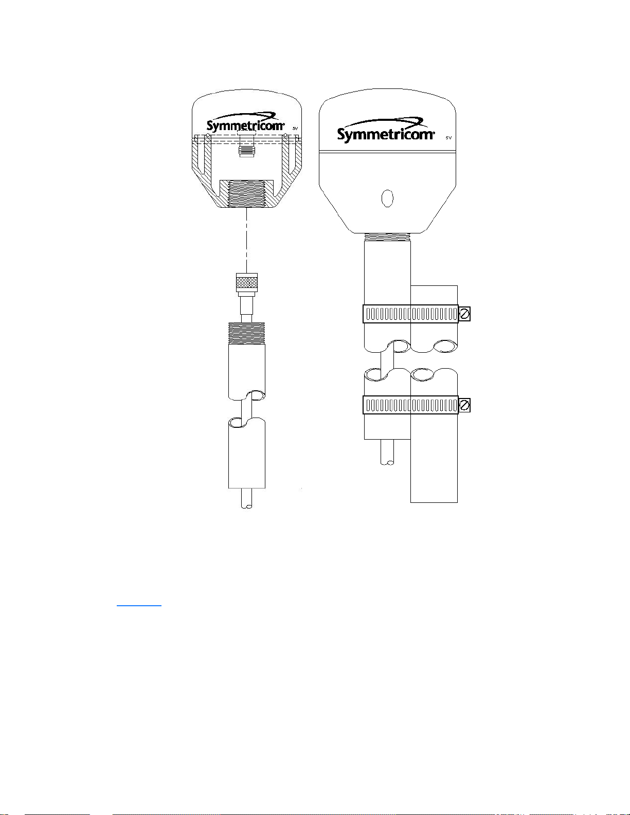
Mounting the GPS Antenna
Mount the GPS antenna on an antenna mast (recommended) or on the peak of a building. For the mast,
use 2-inch (5.08-cm) diameter PVC pipe or conduit that is rigid enough to withstand high winds without
flexing. Use guy wires to stabilize masts longer than 10 ft. (3.048 m). Avoid mounting the antenna on a
tower, which requires a specialist to maintain.
16 XLi IEEE 1588 Clock
997-01510-03, Rev. C, 12/12/2006
SSSSSSSSSSSS SSSSSSSSSS SSSSSSS S SSS S SSSSS S
2
1
5
Figure 3: L1 GPS Antenna - methods for cabling and mounting
GPS Signal Strength Requirements
Refer to Figure 4:The required gain at the GPS receiver’s ANTENNA connector is greater than 20 dB
and less than 36 dB. A 150 foot length of RG-59 coax cable of has a loss of 16-21 dB, which meets this
requirement. Abide by the minimum input gain requirements if using other cable types. Additionally, if
changing the antenna, abide by the 41 dB gain requirement. Other factors, such as radiation, coverage ,
XLi IEEE 1588 Clock 17
997-01510-03, Rev. C, 12/12/2006
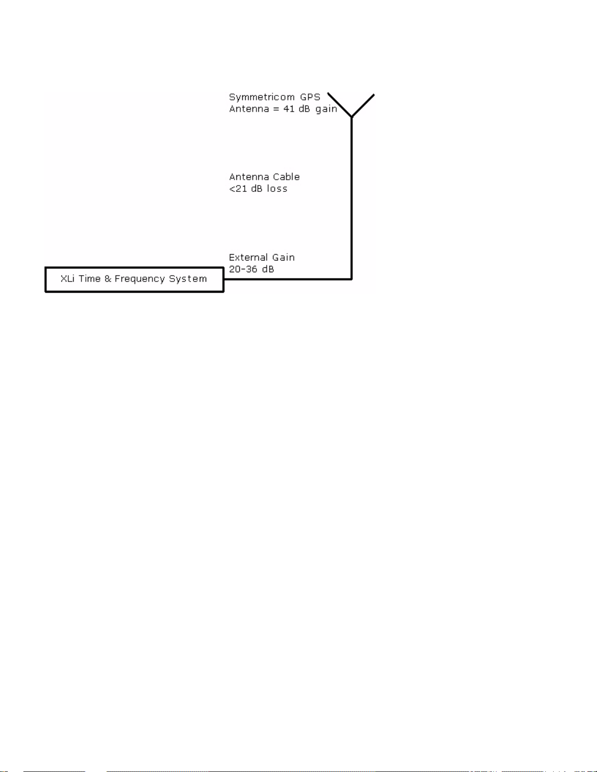
SSSSSSSSSSSS SSSSSSSSSS SSSSSSS S SSS S SSSSS S
VSWR, and input impedance also affect system performance. Symmetricom recommends using the
standard 12-volt capable antenna and cable provided with the GPS receiver.
1
Figure 4: GPS Signal Strength Requirements
Connect the GPS antenna cable to the GPS receiver’s ANTENNA connector at the rear of the XLi.
Note: Use a 12-volt capable GPS antenna.
Making Additional Connections and Powering Up
Make the following connections to the XLi (all cables supplied):
1. For access to the web and command line interfaces, connect NET network po rt (on the Main CPU
Card, 87-8000) to the LAN using the Cat 5 network cable (supplied).
For local access to the command line interface only, connect the SERIAL I/O port (on the Main CPU
Card, 87-8000) to the to the PC’s serial port using a null modem cable.
2. Connect the 1588 network port to the timing network.
3. Connect the AC Power Supply it to a power source. The green STATUS light on the power supply
indicates that the XLi is receiving power.
Upon receiving power, the XLi goes through its startup sequence; displaying “BOOTING”, “LOADING”, and “ST ARTING”. After approxima tely 40 seconds, the XLi displays the clock status, and user
interfaces (front panel/command line) become available. The IEEE 1588 card requires an additional
2 minutes to complete its startup sequence before it is available from the user interfaces.
Warning: Ensure that a disconnect device, such as a switch, with the appropriate voltage/
current rating is provided when operating/installing the XLi.
18 XLi IEEE 1588 Clock
997-01510-03, Rev. C, 12/12/2006

SSSSSSSSSSSS SSSSSSSSSS SSSSSSS S SSS S SSSSS S
Configuring Network Settings
The following steps are required to make the XLi’s Main CPU card operational on a network. Do this if
you plan on using the command line or web interface to manage the XLi over the network.
Using the front panel keypad/display configure the network port settings as follows:
Press Result
ENTER Displays “FUNCTION”
100 Enters 100 as the function number
2
ENTER Displays Function 100’s first screen: “
ENTER Displays “
1-9… Enter the unit’s IP Address (e.g., 192.168.0.11
ENTER Displays “
1-9… Enter the Subnet Mask (e.g., 255.255.255.000)
ENTER Displays “
1-9… Enter the Default Gateway’s IP address (e.g., 192.168.0.1)
ENTER Displays “
ENTER Displays “
ENTER (5 times) Displays “
ENTER Saves the new network parameters, and reboots the XLi
IP ADDRESS…”
SUBNET MASK…”
DEFAULT GATEWAY…”
10-100 BASE-T (CURR BW 10) - AUTO”
REMOTE LOCKOUT – UNLOCK” (Leave unchanged)
SAVE CHANGES – YES”
COMPANY 00-A0-69…”
1
Configuring the XLi
Enter the XLi’s IP address as the address in a browser and log on to the XLi’ s web interface. The factory
set user name is “operator1” and the password is “zeus”. If this XLi was field-upgraded for IEEE 1588
operation, the password may also be “casey”.
5
• Click the Admin Home link and then the Accounts Admin link. Change the factory set user
names and passwords.
• Click the Admin Home link and then the Option Bay # GPS M12 RECEIVER link.
- Verify that the Antenna Cable Delay is correct. For the standard 50 foot (15.24 m) coaxial
cable supplied with the GPS antenna, the Antenna Cable Delay is 60 ns. To compute the correct value for other antenna cable lengths, see “
page 55.
- Leave GPS Operation Mode as “Dynamic” and Time Reference as “Primary”.
• Click the GPS Config & Status link. After approximately 20 minutes of operation, check that
GPS Clock Status is locked and GPS Antenna is OK.
- If GPS Antenna is OK and GPS Clock Status is unlocked, click the GPS Satellite List link.
The Tracked Satellite List should list four or more “current” GPS satellites. It may take significantly longer than 20 minutes for four or more “current” GPS satellites to appear if the GPS
XLi IEEE 1588 Clock 19
997-01510-03, Rev. C, 12/12/2006
F51 – GPS Antenna Cable Delay” on

SSSSSSSSSSSS SSSSSSSSSS SSSSSSS S SSS S SSSSS S
antenna is not in an optimal site or there is a problem with the antenna cable connections. If
this delay is unexpected, consider relocating the GPS antenna to a better site or troubleshooting the GPS antenna cable.
• Press the ST ATUS key on the front panel. The display shou ld show “LOCKED GPS PRI” without
1
an asterisk (“*”). If an asterisk appears, it means that the GPS receiver is currently unlocked
from the GPS satellites, this may indicate a problem with GPS satellite visibility or signal strength.
Configuring the IEEE 1588 Card(s)
Two versions of the XLi IEEE 1588 clock are currently available:
The first version has:
• An IEEE 1588 card configured as a PTP master in Option Bay 4
• A GPS receiver in Option Bay 1
The second version has:
• An IEEE 1588 card configured as a PTP master in Option Bay 4
• An IEEE 1588 card configured as a PTP slave in Option Bay 2
• A GPS receiver in Option Bay 1
Note: With two IEEE cards, be mindful of the Option Bay number when changing the settings.
PTP Master
Note: The IEEE 1588 card requires 5 minutes from power up to initialize. Until then, the card does not
appear in the user interfaces, or is reported as "NOT AVAILABLE".
Function F131 is available for configuring IEEE 1588 cards. The IEEE 1588 card located in Option Bay 4
is preconfigured as a PTP master, as shown here:
• PTP AVAILABILITY - OPTION BAY 4
• PTP IP ADDRESS (STATIC) - 010.048.000.103
• PTP SUBNET MASK (STATIC) - 255.255.000.000
• PTP DEFAULT GATEWAY (STATIC) - 010.024.000.001
• PTP DHCP - ENABLE
• PTP SYNC INTERVAL - 2 SECONDS
• PTP BURST MODE - DISABLE
• PTP PORT STATE - ENABLE
• PTP SUBDOMAIN NAME - _DFLT
• PTP RESET TO FACTORY DFLT? - NO
• PTP INIT TO USER SETTINGS? - NO
• PTP CLOCK CONFIG, BAY 1 - MASTER
20 XLi IEEE 1588 Clock
997-01510-03, Rev. C, 12/12/2006

SSSSSSSSSSSS SSSSSSSSSS SSSSSSS S SSS S SSSSS S
• SLAVE SYNC THRESHOLD - 5 microsec
• PTP PREFERRED MASTER - DISABLE
Note: When two IEEE 1588 cards are present, use the up/down arrow keys to select the PTP master in
Option Bay 4 before making changes.
Using the familiar keypad display interface, modify the following F131 settings:
• If a DHCP server is not available on the timing network, disable DHCP and set static values for
the PTP IP ADDRES, SUBNET MASK, and DEFAULT GATEWAY.
• Configure the following settings on so that the PTP master and PTP slaves match each other:
- PTP SYNC INTERVAL - The rate at which synchronization packets are sent out. The factory
setting, 2 seconds, is the recommended value.
- PTP BURST MODE - Enables quick and accurate synchronization. Generates additional net-
work traffic.
- PTP SUBDOMAIN - Defines the PTP master as a member of a logical timing network.
• (Recommended) Enable PTP PREFERRED MASTER to have P TP slaves on the timing network
favor the PTP grandmaster over other potential masters.
1
2
1
IMPORTANT: If one of the PTP slaves on the timing network is a Symmetricom IEEE 1588 card,
the interval for all PTP masters and PTP slaves must be set to 2 SECONDS.
PTP Slave
To reconfigure the IEEE 1588 card from being a PTP master to being a PTP slave, complete the
following steps:
1. Having logged in to the web interface, from the Admin Homepage, click the link Option Bay 4 IEEE
1588 Master. The new 1588 web page takes approximately 5 seconds to load.
2. Set Clock Configuration to Slave Primary.
5
3. Try operating with Slave Synchronization Threshold at 5 microseconds. Timing networks with bursty
or heavy traffic, routers, or many layers of hubs and switches may nee d the hig her 1000 microsecond setting.
4. Click the Submit Changes button.
5. The front panel display should show "LOCKED PTP PRI" soon after.
The IEEE 1588 card is now operating as a PTP slave and is also functioning as the primary reference
source to the PTP master. The GPS receiver, which was previously operating as the primary reference
source to the IEEE 1588 clock, is now a STANDBY reference source.
1. After saving changes, if DHCP is enabled and a DHCP server is available, F131 displays the DHCP-assigned settings following the PTP DHCP ENABLE screen.
XLi IEEE 1588 Clock 21
997-01510-03, Rev. C, 12/12/2006
SSSSSSSSSSSS SSSSSSSSSS SSSSSSS S SSS S SSSSS S
Note: The IEEE 1588 card configured as a PTP slave relies on TAI as the time scale of the PTP master.
Distributing non-TAI time over PTP while the PTP slave is a reference source will have a predictable effect on the XLi’s system time.
Note: Later on, when reconfiguring the IEEE 1588 card as a PTP master, use F119 to set the GPS
1
receiver as the PRIMARY reference source. (In F119: Set GPS TIME REFERENCE, BAY 1 to
PRIMARY.)
Note: For XLi IEEE 1588 Clocks with the second IEEE 1588 card in Option Bay 2 (preconfigured a PTP
slave, configure the network settings, PTP SYNC INTERVAL, PTP BURST MODE, and PTP
SUBDOMAIN. The factory settings are the same as for the PTP master, except the static IP
Address is 010.048.000.105 and Clock Configuration is Slave Primary.
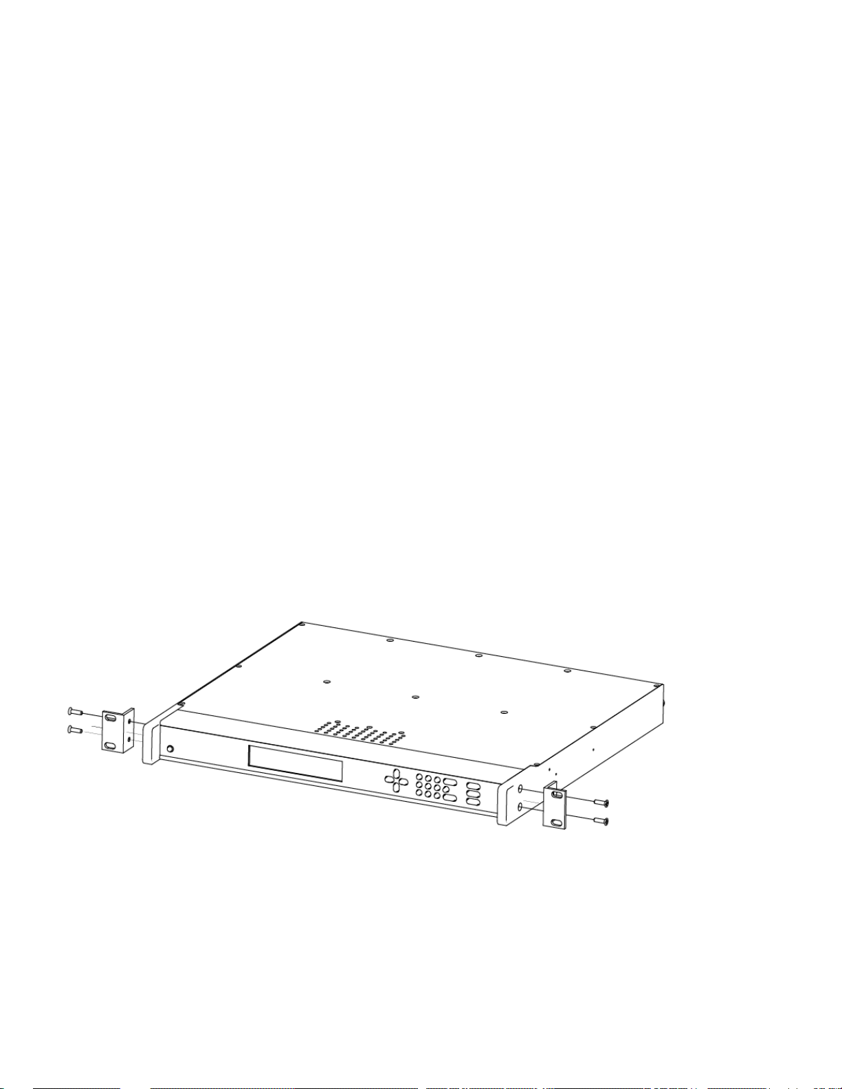
Rack Mounting the XLi
The XLi comes with the following parts needed to mount the XLi securely in any EIA standard 19-inch
(48.26-cm) rack:
• 2 mounting brackets
• 4 flat-head, Phillips screws
Have the following items ready and available:
• The appropriate AC source to connect to the XLi’s power supply.
• A #2 size Phillips bit screwdriver
To rack mount the XLi:
• Unscrew the four phillips-head screws from the front end of the side panels.
• Use the same screws to attach the rack mount brackets, as shown.
• Tighten the screws using a #2 size Phillips screwdriver.
• Position the XLi in any EIA Standard 19-inch (48.26 cm) rack system, and line up holes in the
brackets with the holes in the rack.
22 XLi IEEE 1588 Clock
997-01510-03, Rev. C, 12/12/2006
Loading...