


 Loading...
TimeVaultTM
Trusted Time Server
User’s Manual
6000–100
Revision D
January 2, 2003

The information in this manual is subject to change without notice and should not be construed as a commitment by Symmetricom, Inc. Furthermore, Symmetricom, Inc. reserves the right, without notice, to make changes to equipment design as advances in engineering and manufacturing methods warrant.
The material described in this manual may be used or copied only in accordance with the terms of the license pertaining to the software and hardware referred to herein.
© 2003 Symmetricom, Inc. All rights reserved. Printed in the U.S.A.
The following are registered trademarks or trademarks of their relative companies or organizations: Symmetricom, Symmetricom, Inc.,Microsoft, Microsoft Windows, HyperTerminal, and Procomm. MD5 is the trademark or registered trademark of RSA Security, Inc.
This product includes software derived from the RSA Security, Inc. MD5 Message-Digest Algorithm, which is provided under license from RSA Security, Inc.
Network Time Protocol (NTP) ©David L. Mills 1992-2000.
ii |
TimeVault™ User’s Manual |
6000-100Front.fm Rev. D |

FCC
NOTICE AND COMPLIANCE STATEMENT
Class A
Symmetricom, Inc
Timing, Test, & Measurement Division
3750 Westwind Blvd.
Santa Rosa, Ca. 95403 USA
Declares that the following Models:
TIMEVAULT 6000-100, 6000-101
CONFORM TO THE FOLLOWING FCC NOTICE:
This device has been tested and found to fully compliant with the limits with the FCC Part 15 Subpart B and ICES-003 Class B Limits, using the CISPR 22:1985 specifications and ANSI C63.4:1992 methods. These limits are designed to provide reasonable protection against harmful interference in a residential installation. This device generates, uses, and can radiate radio frequency energy and, if installed and used in accordance with the instruction manual, may cause harmful interference to radio communications. However, there is no guarantee that interference will not occur in a particular installation. If this device does cause harmful interference to radio or television reception, the user is encouraged to try to correct the interference by one or more of the following measures:
∙Reorient or relocate the receiving antenna.
∙Increase the separation between the computer and receiver.
∙Connect the computer into an outlet on a circuit different from that to which the receiver is connected.
∙Consult the dealer or an experienced radio/TV technician for help.
Caution: Any changes or modifications not expressly approved by the grantee of this device could void the user’s authority to operate the equipment.
FCC Compliance Statement
This device complies with Part 15 of the FCC rules. Operation is subject to the following two conditions:
(1) this device may not cause harmful interference, and (2) this device must accept any interference received, including interference that may cause undesired operation.
I declare that the equipment specified above conforms to the above Directives and Standards.
|
04 April 2002 |
Robert Mengelberg |
Compliance Program Manager |
Signature |
|
Date |
Name |
Title |
File: WRM C Drive: TimeVault 6000 FCC Cert.rtf |
Page 1 of 1 |
Rev. A |

DECLARATION OF CONFORMITY
In accordance with ISO/IEC GUIDE 22 and EN 45014
Symmetricom, Inc
Timing, Test, & Measurement Division
3750 Westwind Blvd.
Santa Rosa, Ca. 95403 USA
Declares that the
NETWORK TIME SERVER
MODELS
TIMEVAULT 6000-100, 6000-101
CONFORMS TO THE FOLLOWING EUROPEAN UNION DIRECTIVES:
Safety
73/23/EEC Low Voltage Safety as amended by 93/68/EEC
EN 60950 (Edition 1992) as amended by A1:1993, A2:1993, A3:1995, A4:1997
Electromagnetic Compatibility
89/336/EEC Electromagnetic Compatibility as amended by 92/31/EEC, 93/68/EEC, 98/13/EC EN55022 (1994) EMC Emissions for ITE, Class A as amended by A1:1995 and A2:1995 EN55024 (1998) EMC Immunity for ITE, Class A
EN61000-3-2 (1995) Harmonic Current Emissions as amended by A1 (1998), A2 (1998) EN61000-3-3 (1995) Voltage Fluctuation and Flicker Immunity
Note: The TimeVault is compliant with the supplied standard antenna configuration (Model 142-614-XXX).
If the TimeVault is supplied with a Model 142-6150 Antenna, it has its own CE Compliance Certification.
Initial Certification Issued: |
15 August 2001 |
Certification Updated: 05 October 2001 |
First Date of Marketing With CE Mark: 15 August 2001 |
|
|
I declare that the equipment specified above conforms to the above Directives and Standards.
|
05 October 2001 |
Robert Mengelberg |
Compliance Program Manager |
Signature |
|
Date |
Name |
Title |
I declare that the equipment specified above conforms to the above Directives and Standards.
European Representative:
Company Name and Address
Date |
Name |
Title |
Signature |
|
File: WRM C Drive: TimeVault 6000 CE Cert.rtf |
Page 1 of 1 |
|

Permission to use, copy, modify, and distribute NTP software and its documentation for any purpose and without fee is hereby granted, provided that the above copyright notice appears in all copies and that both the copyright notice and this permission notice appear in supporting documentation, and that the name University of Delaware not be used in advertising or publicity pertaining to distribution of the software without specific, written prior permission. The University of Delaware makes no representations about the suitability of this software for any purpose. It is provided “as is” without express or implied warranty.
6000-100Front.fm Rev. D |
TimeVault™ User’s Manual |
iii |

Settings of TimeVault Ethernet Ports
Record TimeVault network configuration for the NET port below, for quick reference.
NET Port Ethernet Address:___________________________________
NET Port IP Address:________________________________________
NET Port Subnet Mask:______________________________________
NET Port Default Gateway:___________________________________
iv |
TimeVault™ User’s Manual |
6000-100Front.fm Rev. D |

6000-100Front.fm Rev. D |
TimeVault™ User’s Manual |
v |

Please fax or mail this survey back to Symmetricom’s Technical Documentation Department.
Fax: 707-527-6640
Mail: Symmetricom
3750 Westwind Blvd.
Santa Rosa, CA 95403
User’s Manual
Documentation Survey
Our Questions |
Your Answers |
|
|
||||
|
|
|
|||||
Check off the main reasons you consult a manual. |
General information |
|
|||||
|
How to do certain things |
||||||
|
Review, when needed |
|
|||||
|
Emergencies |
|
|
|
|||
|
Other (please list) |
|
|
||||
|
|
|
|
|
|
||
When consulting the manual, can you find the informa- |
not easily |
|
|
|
very easily |
||
tion you need? |
1 |
2 |
3 |
4 |
5 |
6 |
|
(circle the number that fits) |
|
|
|
|
|
|
|
|
|
|
|
||||
Can you find the information you need quickly? |
hard to find |
|
quick and easy to find |
||||
(circle the number that fits) |
1 |
2 |
3 |
4 |
5 |
6 |
|
|
|
|
|
|
|
|
|
Please list any topics that were hard to find. |
|
|
|
|
|
|
|
|
|
|
|
|
|
|
|
Please list any topics that you couldn’t find at all. |
|
|
|
|
|
|
|
|
|
|
|
||||
How clearly is the manual organized? |
not clearly |
|
very clearly |
||||
(circle the number that fits) |
1 |
2 |
3 |
4 |
5 |
6 |
|
|
|
|
|
||||
Is the manual a useful size for you? |
much too large |
|
just right |
||||
(circle the number that fits.) |
1 |
2 |
3 |
4 |
5 |
6 |
|
|
|
|
|
|
|||
Is the font easy to read? |
Big enough? |
Yes |
|
No |
|||
|
Easy on the eyes? Yes |
No |
|||||
|
|
|
|
|
|
|
|
Would you like more educational information included |
Yes |
|
No |
|
|
|
|
about time and frequency in general? |
|
|
|
|
|
|
|
|
|
|
|
|
|||
If Symmetricom published a thin, very basic, “how to” |
I’d prefer it. |
|
|
|
|||
manual without all the detail and technical information in |
I’d use them both. |
|
|
||||
the current manual, would you have any use for such a |
|
|
|||||
I probably wouldn’t use it. |
|||||||
publication? |
|||||||
|
|
|
|
|
|
||
|
|
|
|
|
|
|
|
Do you have use for an electronic (PDF) version of this |
Yes |
|
No |
|
|
|
|
manual? |
If YES (and if you do not already have |
||||||
|
one), give us your email address and we |
||||||
|
will email you a PDF copy. |
||||||
|
|
|
|
|
|
|
|
vi |
TimeVault™ User’s Manual |
6000-100Front.fm Rev. D |

On a scale of 1- 6, please rate the following sections of the User’s Manual for:
•clarity
•completeness
•usefulness
Circle the number of your rating: 1-2 = Unacceptable; 3-4 = Meets Expectations; 5 = Exceeds Expectations; 6 = Outstanding
|
Unacceptable |
Meets |
|
Exceeds |
|
||
|
|
|
Expectations |
Expectations Outstanding |
|||
|
|
|
|
|
|
|
|
General Information |
1 |
2 |
3 |
4 |
5 |
6 |
|
(including Specs) |
|
|
|
|
|
|
|
|
|
|
|
|
|
|
|
Installation (cabling) |
1 |
2 |
3 |
4 |
5 |
6 |
|
|
|
|
|
|
|
|
|
Quick Start Guide |
1 |
2 |
3 |
4 |
5 |
6 |
|
|
|
|
|
|
|
|
|
Web/Telnet Access |
1 |
2 |
3 |
4 |
5 |
6 |
|
|
|
|
|
|
|
|
|
Keypad Functions |
1 |
2 |
3 |
4 |
5 |
6 |
|
|
|
|
|
|
|
|
|
Serial I/O Functions |
1 |
2 |
3 |
4 |
5 |
6 |
|
|
|
|
|
|
|
|
|
Error (and other) Messages |
1 |
2 |
3 |
4 |
5 |
6 |
|
|
|
|
|
|
|
|
|
Appendix A (NTP) |
1 |
2 |
3 |
4 |
5 |
6 |
|
|
|
|
|
|
|
|
|
Appendix B (MD5) |
1 |
2 |
3 |
4 |
5 |
6 |
|
|
|
|
|
|
|
|
|
Appendix C |
1 |
2 |
3 |
4 |
5 |
6 |
|
(Time/Daytime Protocols) |
|||||||
|
|
|
|
|
|
||
|
|
|
|
|
|
|
|
Appendix D (SNMP) |
1 |
2 |
3 |
4 |
5 |
6 |
|
|
|
|
|
|
|
|
|
Appendix E (ACTS) |
1 |
2 |
3 |
4 |
5 |
6 |
|
|
|
|
|
|
|
|
|
Table of Contents |
1 |
2 |
3 |
4 |
5 |
6 |
|
|
|
|
|
|
|
|
|
Index |
1 |
2 |
3 |
4 |
5 |
6 |
|
|
|
|
|
|
|
|
|
Please also write down any other suggestions for improving this manual:
6000-100Front.fm Rev. D |
TimeVault™ User’s Manual |
vii |

viii |
TimeVault™ User’s Manual |
6000-100Front.fm Rev. D |
Table of Contents
1
2
Table of Contents i
General Information 1
Conventions . . . . . . . . . . . . . . . . . . . . . . . . . . . . . . . . . . . . . . . . . . . . 1
Overview of TimeVault . . . . . . . . . . . . . . . . . . . . . . . . . . . . . . . . . . . 2
Limited Warranty . . . . . . . . . . . . . . . . . . . . . . . . . . . . . . . . . . . . . . . . 2
Limitation Of Liability . . . . . . . . . . . . . . . . . . . . . . . . . . . . . . . . . . . . 2
Proprietary Notice . . . . . . . . . . . . . . . . . . . . . . . . . . . . . . . . . . . . . . . 3
Physical Specifications . . . . . . . . . . . . . . . . . . . . . . . . . . . . . . . . . . . 3
Environmental Specifications . . . . . . . . . . . . . . . . . . . . . . . . . . . . . . 4
Power Input Specifications . . . . . . . . . . . . . . . . . . . . . . . . . . . . . . . . 5
Certifications. . . . . . . . . . . . . . . . . . . . . . . . . . . . . . . . . . . . . . . . . . . 5
Internal Timing Performance Specifications . . . . . . . . . . . . . . . . . . . 5
Network Time Protocol Synchronization Specifications . . . . . . . . . 6
Front Panel Interface . . . . . . . . . . . . . . . . . . . . . . . . . . . . . . . . . . . . . 7
Interface Specifications . . . . . . . . . . . . . . . . . . . . . . . . . . . . . . . . . . . 8
NET Port Ethernet Interface . . . . . . . . . . . . . . . . . . . . . . . . . . . . 8
Utility Port (RS-232 I/O Interface) . . . . . . . . . . . . . . . . . . . . . . . 8
ACTS Port . . . . . . . . . . . . . . . . . . . . . . . . . . . . . . . . . . . . . . . . . . 9
3 Installation and Start-Up 11
Site Preparation . . . . . . . . . . . . . . . . . . . . . . . . . . . . . . . . . . . . . . . . 11
Mounting Instructions . . . . . . . . . . . . . . . . . . . . . . . . . . . . . . . . 11
Necessary Equipment . . . . . . . . . . . . . . . . . . . . . . . . . . . . . . . . 12
Antenna Information . . . . . . . . . . . . . . . . . . . . . . . . . . . . . . . . . 13
GPS Roof-Mounted Antenna Installation . . . . . . . . . . . . . . . . . 13
GPS Window-Mounted Antenna (140-619) Installation . . . . . . 14
Cabling . . . . . . . . . . . . . . . . . . . . . . . . . . . . . . . . . . . . . . . . . . . . . . . 15
Power-Up . . . . . . . . . . . . . . . . . . . . . . . . . . . . . . . . . . . . . . . . . . . . . 17
GPS Mode . . . . . . . . . . . . . . . . . . . . . . . . . . . . . . . . . . . . . . . . . 17
ACTS Mode . . . . . . . . . . . . . . . . . . . . . . . . . . . . . . . . . . . . . . . . 19
NTP Mode . . . . . . . . . . . . . . . . . . . . . . . . . . . . . . . . . . . . . . . . . 19
Synchronization Source Operation . . . . . . . . . . . . . . . . . . . . . . 20
Rolling Redundancy . . . . . . . . . . . . . . . . . . . . . . . . . . . . . . . . . 22
Front Panel Interface . . . . . . . . . . . . . . . . . . . . . . . . . . . . . . . . . . . . 23
Alphanumeric Display . . . . . . . . . . . . . . . . . . . . . . . . . . . . . . . . 23
Keypad Operation . . . . . . . . . . . . . . . . . . . . . . . . . . . . . . . . . . . 24
NET Port Network Parameters: First Time Configuration . . . . . . . 28
DHCP Configuration . . . . . . . . . . . . . . . . . . . . . . . . . . . . . . . . . . . . 29
Verify Functionality . . . . . . . . . . . . . . . . . . . . . . . . . . . . . . . . . . . . . 29
6000-100FrontTOC.fm Rev. D |
TimeVault™ User’s Manual |
TOC-i |

Table of Contents
Wrap-Up & Advanced Operation . . . . . . . . . . . . . . . . . . . . . . . . . . 29
4 Remote Operation 31
Web Access . . . . . . . . . . . . . . . . . . . . . . . . . . . . . . . . . . . . . . . . . . . 31
Starting the Web Browser . . . . . . . . . . . . . . . . . . . . . . . . . . . . . 31
Accessing TimeVault’s Web Pages . . . . . . . . . . . . . . . . . . . . . . 32
Configuration Control Login Page . . . . . . . . . . . . . . . . . . . . . . 33
Remote Configuration. . . . . . . . . . . . . . . . . . . . . . . . . . . . . . . . . 34
Leaving the Control Pages . . . . . . . . . . . . . . . . . . . . . . . . . . . . . 39
Leaving the Web Interface . . . . . . . . . . . . . . . . . . . . . . . . . . . . . 39
Telnet Access . . . . . . . . . . . . . . . . . . . . . . . . . . . . . . . . . . . . . . . . . . 40
Starting Telnet and Making a Connection . . . . . . . . . . . . . . . . . 40
Ending Telnet . . . . . . . . . . . . . . . . . . . . . . . . . . . . . . . . . . . . . . . 41
Serial Access . . . . . . . . . . . . . . . . . . . . . . . . . . . . . . . . . . . . . . . . . . 42
Serial Line Settings . . . . . . . . . . . . . . . . . . . . . . . . . . . . . . . . . . 42
HyperTerminal . . . . . . . . . . . . . . . . . . . . . . . . . . . . . . . . . . . . . . 43
Session Timers . . . . . . . . . . . . . . . . . . . . . . . . . . . . . . . . . . . . . . . . . 48
Utility Port Session Timer . . . . . . . . . . . . . . . . . . . . . . . . . . . . . 48
Telnet Session Timer . . . . . . . . . . . . . . . . . . . . . . . . . . . . . . . . . 48
Web Control Session Timer . . . . . . . . . . . . . . . . . . . . . . . . . . . . 48
5 |
Serial or Telnet I/O Functions 49 |
|
||
Overview and Format . . . . . . . . . . . . . . . . . . . . . . . . . . . . . . . . . |
. . 49 |
|||
Command List . . . . . . . . . . . . . . . . . . . . . . . . . . . . . . . . . . . . . . . |
. . 51 |
|||
Function Commands . . . . . . . . . . . . . . . . . . . . . . . . . . . . . . . . . . . |
. 54 |
|||
|
F03 |
– Time and Date Request . . . . . . . . . . . . . . . . . . . . . . . . . |
. 54 |
|
|
F18 |
– Software Version Request . . . . . . . . . . . . . . . . . . . . . . . |
. 54 |
|
|
F36 |
– NET Port Network Configuration Entry/Request . . . . . |
. 55 |
|
|
F53 |
– Operating Mode Request . . . . . . . . . . . . . . . . . . . . . . . . |
. 55 |
|
|
F60 |
– Satellite List Request . . . . . . . . . . . . . . . . . . . . . . . . . . . |
. 56 |
|
|
F67 |
– Leap Second Information . . . . . . . . . . . . . . . . . . . . . . . |
. 58 |
|
|
F72 |
– Fault Status Request . . . . . . . . . . . . . . . . . . . . . . . . . . . |
. 58 |
|
Extended Function Commands . . . . . . . . . . . . . . . . . . . . . . . . . . . |
. 59 |
|||
|
F100 BASET – 100 BASE-T/10 BASE-T Control . . . . . . . . . |
. 60 |
||
|
F100 DHCP – DHCP Control . . . . . . . . . . . . . . . . . . . . . . . . . |
. 61 |
||
|
F100 |
EA – Ethernet Address . . . . . . . . . . . . . . . . . . . . . . . . . . |
. 62 |
|
|
F100 |
IP – IP Address . . . . . . . . . . . . . . . . . . . . . . . . . . . . . . . . |
. 62 |
|
|
F100 SM – Subnet Mask . . . . . . . . . . . . . . . . . . . . . . . . . . . . . |
. 63 |
||
|
F100 G – Gateway . . . . . . . . . . . . . . . . . . . . . . . . . . . . . . . . . . |
. 63 |
||
|
F100 |
IC – NET Port Network Configuration Entry/Request |
. . 64 |
|
|
F100 |
P – Change User Password . . . . . . . . . . . . . . . . . . . . . . . |
. 64 |
|
|
F100 |
ST – Self Test Status . . . . . . . . . . . . . . . . . . . . . . . . . . . . |
. 65 |
|
|
F100 |
VER – Software Version Request . . . . . . . . . . . . . . . . . . |
. 66 |
|
TOC-ii |
TimeVault™ User’s Manual |
6000-100FrontTOC.fm Rev. D |

Table of Contents
|
F100 |
T – Current Time Source Request . . . . . . . . . . . . . . . . . . |
66 |
|
F100 CONFIG – FTP Configuration of NTP, SNMP & ACTS Parameters 67 |
||
|
F100 LOCK – Remote Lockout . . . . . . . . . . . . . . . . . . . . . . . . . |
76 |
|
|
F100 |
L – Lock Display Request . . . . . . . . . . . . . . . . . . . . . . . . |
76 |
|
F100 |
J - Jumper . . . . . . . . . . . . . . . . . . . . . . . . . . . . . . . . . . . . . |
77 |
|
F100 BH - Burn Host . . . . . . . . . . . . . . . . . . . . . . . . . . . . . . . . . |
77 |
|
|
F100 BU - Burn . . . . . . . . . . . . . . . . . . . . . . . . . . . . . . . . . . . . . |
77 |
|
|
F100 BUB - Burn BootLoader . . . . . . . . . . . . . . . . . . . . . . . . . . |
79 |
|
|
F100 |
BF - Burn File System . . . . . . . . . . . . . . . . . . . . . . . . . . . |
79 |
|
F100 K I L L - Reboot . . . . . . . . . . . . . . . . . . . . . . . . . . . . . . . . |
80 |
|
|
F100 |
BL - Burn Host Lock Request . . . . . . . . . . . . . . . . . . . . . |
81 |
|
F100 |
BLS - Burn Host Lock Set . . . . . . . . . . . . . . . . . . . . . . . . |
81 |
|
F100 |
BLR - Burn Host Lock Reset . . . . . . . . . . . . . . . . . . . . . . |
81 |
|
F100 PRESETALL - Password Reset All . . . . . . . . . . . . . . . . . |
82 |
|
|
F100 PN - Password System User Name Change . . . . . . . . . . . |
82 |
|
|
F100 |
PR - Password Reset . . . . . . . . . . . . . . . . . . . . . . . . . . . . . |
83 |
|
F100 |
PL - Password Lock Request . . . . . . . . . . . . . . . . . . . . . . |
83 |
|
F100 |
PLS - Password Lock Set . . . . . . . . . . . . . . . . . . . . . . . . . |
84 |
|
F100 |
PLR - Password Lock Reset . . . . . . . . . . . . . . . . . . . . . . . |
84 |
|
F100 |
PE LIST - Peer List Request . . . . . . . . . . . . . . . . . . . . . . . |
84 |
|
F100 PE ADD - Peer Add . . . . . . . . . . . . . . . . . . . . . . . . . . . . . |
85 |
|
|
F100 PE REM - Peer Remove . . . . . . . . . . . . . . . . . . . . . . . . . . |
85 |
|
|
F100 PI - PING . . . . . . . . . . . . . . . . . . . . . . . . . . . . . . . . . . . . . |
85 |
|
|
F100 PT - Time . . . . . . . . . . . . . . . . . . . . . . . . . . . . . . . . . . . . . |
85 |
|
Login/Logout . . . . . . . . . . . . . . . . . . . . . . . . . . . . . . . . . . . . . . . . . . |
86 |
||
|
Operator Login . . . . . . . . . . . . . . . . . . . . . . . . . . . . . . . . . . . . . . |
86 |
|
|
Guest Login . . . . . . . . . . . . . . . . . . . . . . . . . . . . . . . . . . . . . . . . |
86 |
|
|
Logout . . . . . . . . . . . . . . . . . . . . . . . . . . . . . . . . . . . . . . . . . . . . |
86 |
|
6 |
TimeVault-Generated Messages 87 |
|
|
Error Messages . . . . . . . . . . . . . . . . . . . . . . . . . . . . . . . . . . . . . . . . |
87 |
||
LED System Status Alerts . . . . . . . . . . . . . . . . . . . . . . . . . . . . . . . . |
89 |
||
|
Solid Red/Solid Orange . . . . . . . . . . . . . . . . . . . . . . . . . . . . . . . |
89 |
|
Informational Messages . . . . . . . . . . . . . . . . . . . . . . . . . . . . . . . . . . |
89 |
||
A NTP Version 3, NTPQ, and NTPDC 91
NTP V 3.0 Data Format per RFC-1305 . . . . . . . . . . . . . . . . 91
NTP Data Packet . . . . . . . . . . . . . . . . . . . . . . . . . . . 91
SNTP V 3.0 Data Format per RFC-2030 . . . . . . . . . . . . . . 95
Cross Check Functionality with NTPQ and NTPDC . . . . . . 96
NTPQ . . . . . . . . . . . . . . . . . . . . . . . . . . . . . . . . . . . 96
NTPDC . . . . . . . . . . . . . . . . . . . . . . . . . . . . . . . . . . 96
6000-100FrontTOC.fm Rev. D |
TimeVault™ User’s Manual |
TOC-iii |

Table of Contents
For more information . . . . . . . . . . . . . . . . . . . . . . . . 96
B MD5 Authentication and NTP Broadcast Mode 99
Introduction to MD5 . . . . . . . . . . . . . . . . . . . . . . . . . . . . . . |
. 99 |
NTP Broadcast Mode with MD5 Authentication . . . . . . . . |
101 |
NTP Broadcast Mode without Authentication . . . . . . . . . . |
102 |
Configuration of NTP on the Timeserver . . . . . . . . |
102 |
Configuration of NTP on the Time Client . . . . . . . |
103 |
C TIME and DAYTIME Protocols 105
TIME Protocol as per RFC-868 . . . . . . . . . . . . . . . . . . . . . 105 The Time Protocol Format . . . . . . . . . . . . . . . . . . 105 DAYTIME Protocol as per RFC-867 . . . . . . . . . . . . . . . . . 106 TCP Based Daytime Service . . . . . . . . . . . . . . . . . 106 UDP Based Daytime Service . . . . . . . . . . . . . . . . 106 DAYTIME String Format . . . . . . . . . . . . . . . . . . . . 106
D SNMP – Simple Network Management Protocol 107
About SNMP . . . . . . . . . . . . . . . . . . . . . . . . . . . . . . . . . . . 107 Symmetricom SNMP Configuration . . . . . . . . . . . . . . . . . 108 Serial or Telnet Configuration . . . . . . . . . . . . . . . . . . . . . . 110 Symmetricom SNMP Enterprise MIB . . . . . . . . . . . . . . . . 110
E F
Automated Computer Time Service (ACTS) 125
Non-Standard Features 127
Index
TOC-iv |
TimeVault™ User’s Manual |
6000-100FrontTOC.fm Rev. D |

1
General Information
This manual provides you with all of the information necessary to properly install and operate the TimeVault™ Time Server (hereafter referred to as TimeVault). Optimization for time functionality means that accurate position readouts are not available. The information in this manual includes any normal maintenance and adjustment data that may be required to facilitate field repairs.
1.1Conventions
The conventions used in this manual are:
Text |
= |
Indicates body text. |
|||
Italics |
= |
Emphasizes important information. |
|||
|
|
|
|
= |
Used with bold text to call attention to important information. |
|
|
|
|
||
<Key> |
= |
For input, referring to keys that are labeled on your keyboard. |
|||
|
|
|
|
|
For example, <Enter> means press the Enter key for a line |
|
|
|
|
|
terminator; <SP> means press the spacebar to enter a space. |
KEYPAD PUSH |
|
|
|||
BUTTONS |
= |
Used to indicate push-buttons on the unit: Press SAVE |
|||
Bold |
= |
Used to show messages, prompts, menus, items in selection |
|||
|
|
|
|
|
lists, etc., that appear on a computer screen and require action |
|
|
|
|
|
on your part. For example, Press the Submit Changes button. |
text |
= |
Used to display output character strings. |
|||
text |
= |
Used to indicate text you should enter with your keyboard, |
|||
|
|
|
|
|
exactly as printed. |
6000-100Ch1.fm Rev. D |
TimeVault™ User’s Manual |
1-1 |

Chapter 1: General Information |
Overview of TimeVault |
1.2Overview of TimeVault
TimeVault is a high-performance, internet-enabled Network Time Protocol (NTP) server that operates in a secure access environment and provides time to multiple clients with extreme accuracy. To provide trusted time and guard against any denial of service, TimeVault uses GPS as a primary synchronization source, backed up by ACTS and NTP as secondary and tertiary sources, respectively.
TimeVault provides network time synchronization over Ethernet connected networks via Network Time Protocol (NTP), developed by Dr. David Mills at the University of Delaware. TimeVault currently supports versions 2 and higher of the NTP, RFC-1305, as well as the Simple Network Time Protocol (SNTP), RFC-2030. In addition, TimeVault responds to TIME protocol requests, RFC-868. For details about these protocols, refer to Appendix A and Appendix B in this manual.
The main feature of TimeVault’s web interface is its ability to perform setup and control operations from a remote location, using the Internet or TCP/IP LAN (see Chapter 3). The protocol used is either Telnet or HTTP. TimeVault has an RJ-45 Ethernet connector on its NET Port, providing NTP and IP access, and a 9-pin D serial connector for serial input/output.
1.3Limited Warranty
Each new product manufactured by Symmetricom is warranted for defects in material or workmanship for a period of one year from date of shipment (“Limited Warranty”). Defects in material or workmanship found within that period will be replaced or repaired, at Symmetricom's option, without charge for material or labor, provided the customer returns the equipment, freight prepaid, to the Symmetricom factory under this limited warranty. Symmetricom will return the repaired equipment, freight prepaid, to the customer's facility. This one year Limited Warranty does not apply to any software or to any product not manufactured by Symmetricom.
1.4Limitation Of Liability
By purchasing any product from Symmetricom, the Buyer consents to and agrees that the Buyer's sole and exclusive remedy for any damages or losses incurred by the Buyer, as a result of Symmetricom's breach of its one-year Limited Warranty for defects in materials and workmanship or otherwise in connection with any claim respecting the product, shall be limited to the repair or replacement of the product or a refund of the sales price of the product.
In no event shall the Buyer be entitled to recover consequential damages or any other damages of any kind or description whatsoever.
1-2 |
TimeVault™ User’s Manual |
6000-100Ch1.fm Rev. D |

Proprietary Notice |
Chapter 1: General Information |
1.5Proprietary Notice
THIS DOCUMENT, WHETHER PATENTABLE OR NON-PATENTABLE SUBJECT MATTER, EMBODIES PROPRIETARY AND CONFIDENTIAL INFORMATION AND IS THE EXCLUSIVE PROPERTY OF SYMMETRICOM, INC. IT MAY NOT BE REPRODUCED, USED OR DISCLOSED TO OTHERS FOR ANY PURPOSE EXCEPT THAT FOR WHICH IT IS PURCHASED OR LOANED.
1.6Physical Specifications
TimeVault fits in a standard 1U (1.75-inch [4.445-cm]) high, 19-inch (48.26 cm) rack mount package (see page 2-11 for mounting instructions) and has the following physical specifications:
TimeVault Chassis, with rails and handles
Size: |
1.73 in x 17.00 in x 11.63 in (4.39 cm x 43.18 cm x 29.54 cm) |
|
|
Weight: |
4.21 lb max. (1.91 kg) |
|
|
Standard Antenna |
|
|
|
Size: |
2.625 in dia. x 1.5 in (6.67 cm dia. x 3.81 cm) |
|
|
Weight: |
0.55 lb (0.250 kg) (including mounting mast) |
|
|
Power Regulated: |
+12 V @ <25 mA |
|
|
Frequency (L1): |
1575.42 MHz |
|
Coarse Acquisition (C/A) Code |
|
|
Optional Down/Up Converter
If you have this option, please refer to the manual for:
Symmetricom Model 142-6150, Antenna Down/Up Converter
Antenna Cable (for Standard Antenna)
Type: |
RG-59 |
|
Attenuation at 1575.42 MHz should be no more than 10.5 dB per |
|
100 feet (Belden 9104 or equivalent) |
|
|
Length: |
50 ft (15.24 m) [available in lengths up to 200 ft (60.96 m)] |
|
|
Weight: |
1.2 lb (0.545 kg) |
|
|
Antenna Cable (for optional Down/Up Converter Antenna)
If you have this option, please refer to the manual for:
Symmetricom Model 142-6150, Antenna Down/Up Converter
TimeVault requires a 12 V antenna and may severely damage any antenna that does not support 12 V. For non-standard antenna types, contact Symmetricom for assistance.
6000-100Ch1.fm Rev. D |
TimeVault™ User’s Manual |
1-3 |

Chapter 1: General Information |
Environmental Specifications |
1.7Environmental Specifications
The environmental specifications of TimeVault are:
Operating Temperature
TimeVault Module: |
0 to +50 °C (+32 to +122 °F) |
|
|
Antenna: |
–40 to +70 °C (–40 to +158° F) |
|
|
Maximum Rate of Change: |
8 °C per hour |
|
|
Storage Temperature |
|
|
|
TimeVault Module: |
–50 to +85 °C (–40 to +185 °F) |
|
|
Antenna: |
–55 to +85 °C (–67 to +185 °F) |
|
|
Maximum Rate of Change: |
15 °C per hour |
|
|
Operating Humidity |
|
|
|
TimeVault Module: |
0% up to 95%, non-condensing |
|
|
Antenna: |
100%, condensing |
|
|
Storage Humidity |
|
|
|
TimeVault Module: |
0% up to 95%, non-condensing |
|
|
Antenna: |
100%, condensing |
|
|
Operating Altitude |
|
|
|
TimeVault Module: |
Maximum 4 km |
|
|
Storage Altitude |
|
|
|
TimeVault Module: |
Maximum 12 km |
|
|
Shock & Vibration Requirements |
|
|
|
In Shipping Container: |
Per ISTA Procedure 2A |
|
|
Bench Handling without Shipping |
Per EN60068-2-31 |
Container: |
|
|
|
1-4 |
TimeVault™ User’s Manual |
6000-100Ch1.fm Rev. D |

Power Input Specifications |
Chapter 1: General Information |
1.8Power Input Specifications
The power input specifications of TimeVault are:
Power Input
AC Mains: |
100 to 240 VAC, 47-440 Hz |
(base model) |
IEC 320 Connector |
|
|
–48 VDC |
–36 to –60 VDC |
(optional): |
4 position Barrier Strip Connection |
|
Fuse: 1A Slow-Blow (rear panel) |
|
|
Power Requirement: |
<20 W maximum |
|
|
1.9Certifications
FCC
CE (applies to base model only)
UL (applies to base model only)
1.10Internal Timing Performance Specifications
The timing accuracy achievable with this product depends on several factors. The most important is the method TimeVault employs to use the NTP information. It is widely accepted that the uncertainty of any single NTP packet is on the order of 10 ms. However, most NTP client programs perform averaging and filtering over several NTP transfers, improving the accuracy and removing the systematic delays. The performance of the various NTP clients varies widely, but some are able to achieve accuracies below 1 ms.
Inherent accuracy:
•With GPS synchronization, approximately 125 µs (this accuracy exceeds that which the NTP protocol delivers over a network)
•With ACTS synchronization, 5 ms.
In this case, the system accuracy is limited to the accuracy of the ACTS input.
•With NTP client mode synchronization, the accuracy of the client software is the limiting factor in determining the delivered time accuracy.
•Accuracy of packet delivery time to network jack: <0.5 ms
Network timing accuracy is limited to 1-10 ms typical.
During a synchronization input outage, following initial synchronization of TimeVault to its input synchronization sources, the time maintained in the unit diverges from the input at the rate of approximately 6 parts in 10-6, if the ambient temperature is maintained within ± 3 °C.
6000-100Ch1.fm Rev. D |
TimeVault™ User’s Manual |
1-5 |

Chapter 1: General Information |
Network Time Protocol Synchronization Specifications |
1.11Network Time Protocol Synchronization Specifications
TimeVault’s hardware is specifically designed to implement the NTP server function. As such, it was carefully designed to minimize the unknown latencies in timestamping received and transmitted NTP packets. The NTP timestamp accuracy specifications are:
Received Timestamp Accuracy: <0.1 ms, relative to synchronization source Transmitted Timestamp Accuracy: <0.1 ms, relative to synchronization source
At these levels, the realizable NTP synchronization accuracy of any host is determined by the repeatability of network and client delays, not by TimeVault’s timestamp uncertainty.
TimeVault supports the following protocols: |
|
|
• |
Telnet . . . . . . . . . . . . . . . . . . . . . . . . . . . . . . . . . . . . . . |
RFC-854 |
• |
DAYTIME (available in TCP and UDP protocols) . . . . . . . . . |
RFC-867 |
• |
TIME (available in TCP and UDP protocols) . . . . . . . . . . . . . |
RFC-868 |
• |
FTP . . . . . . . . . . . . . . . . . . . . . . . . . . . . . . . . . . . . . . . . |
RFC-959 |
• |
SMI . . . . . . . . . . . . . . . . . . . . . . . . . . . . . . . . . . . . . . . . |
RFC-1155 |
• |
SNMP . . . . . . . . . . . . . . . . . . . . . . . . . . . . . . . . . . . . . . |
RFC-1157 |
• |
MIB. . . . . . . . . . . . . . . . . . . . . . . . . . . . . . . . . . . . . . . . |
RFC-1212 |
• |
MIB II . . . . . . . . . . . . . . . . . . . . . . . . . . . . . . . . . . . . . . |
RFC-1213 |
• |
NTP ver. 4.0 . . . . . . . . . . . . . . . . . . . . . . . . . . . . . . . . . |
N/A |
|
(backwards compatible with NTP ver.2, RFC-1119, and ver.3, RFC-1305**) |
|
• |
MD5 . . . . . . . . . . . . . . . . . . . . . . . . . . . . . . . . . . . . . . . |
RFC-1321 |
• |
SNTP . . . . . . . . . . . . . . . . . . . . . . . . . . . . . . . . . . . . . . |
RFC-2030 |
• |
HTTP . . . . . . . . . . . . . . . . . . . . . . . . . . . . . . . . . . . . . . |
RFC-2068 and 2616 |
• |
DHCP . . . . . . . . . . . . . . . . . . . . . . . . . . . . . . . . . . . . . . |
RFC-2132 |
*SMI = Structure of Management Information
**TimeVault does not implement the “authenticator field” of the NTP packet as described in Appendix C of RFC-1305.
Complete RFC information is available at http://www.ietf.org/
An NTP or SNTP client, compatible with the computer platform you use and configured to use TimeVault’s NET Port IP address, is required for accurate network synchronization. In this manual, refer to Appendix A and Appendix B for details about NTP and SNTP protocols, and Appendix D for details about SNMP and MIB.
Note: A number of NTP-related programs, such as NTPDC and NTPQ, are not supported, in the conventional sense, by Dr. Mills’ NTP, and therefore cannot be supported by Symmetricom, Inc. (TrueTime, Inc. is now Symmetricom, Inc.). The user of these programs does so at his or her own risk.
1-6 |
TimeVault™ User’s Manual |
6000-100Ch1.fm Rev. D |
Front Panel Interface |
Chapter 1: General Information |
1.12Front Panel Interface
This section provides a general description of TimeVault’s front panel input devices. For details about how to enter commands and interpret display readouts, see “Overview and Format” on page 4-49.
TimeVault’s front panel is your primary interface with the system. Input is through six keypad buttons (four directional, SET-UP and SAVE). Output is through the two-line, 20-character alphanumeric display (see Figure 1-1, below). The letter at the end of the output date line indicates the synchronization source in use (G for GPS, A for ACTS and N for NTP).
Two front panel mounted, tri-color LEDs reflect the status of TimeVault. The system status indicator at the left end of the front panel has five different displays:
If the System Status Displays... |
It Means... |
|
|
Solid Red |
No signal from time sources, |
|
or major alarm fault detected |
|
|
Solid Orange |
TimeVault is synchronized to Network Time |
|
Servers through NTP |
|
|
Blinking Green |
The primary or secondary synchronization |
|
source(s) is fully operational |
|
|
Possible causes and solutions for problems resulting in a solid red or solid orange display are discussed in “LED System Status Alerts” on page 5-89.
The connection active indicator, labeled “ACT” and located to the right of the NET Port’s RJ-45 plug, indicates the connection speed on the NET Port.
|
Alphanumeric |
SET-UP and SAVE Push-Button |
NET Port Serial I/O |
Display |
|
|
|
|
|
|
|
|
|
|
|
|
|
|
|
|
|
|
|
|
|
|
|
|
|
|
|
|
|
|
|
|
|
|
|
|
|
|
|
|
|
|
|
|
|
System |
Connection Active |
|
|
|
|
|
||
Status |
(“ACT”) |
|
Directional Push-Buttons |
|||||
Indicator |
Indicator |
|
||||||
Figure 1-1 TimeVault Front Panel
6000-100Ch1.fm Rev. D |
TimeVault™ User’s Manual |
1-7 |

Chapter 1: General Information |
Interface Specifications |
1.13Interface Specifications
1.13.1NET Port Ethernet Interface
Type: |
Standard RJ-45 8-pin connector for 10Base-T and 100Base-T |
|
|
standards |
|
Frame Format: IEEE 802.3 |
|
|
Supported Protocols/Applications: |
|
|
|
Telnet |
HTTP |
|
DHCP |
SNTP |
|
TCP/IP |
SNMP |
|
TFTP or FTP |
NTP and Broadcast NTP |
1.13.2Utility Port (RS-232 I/O Interface)
Data: |
Serial functions (as listed in Section 4.3, “Function Commands,” on |
|
page 4-54) |
Data Rates: |
9600 |
Data Bits: |
8 |
Parity: |
None |
Stop Bits: |
1 |
Connector: |
Male 9-pin D subminiature (wired as DTE, located on the front |
|
panel) |
Serial I/O settings are factory set and cannot be changed.
The following chart shows pin assignments for the RS-232 connector:
Table 1-1 RS-232 Interface Pin Assignments
Pin |
Assignment |
|
|
1 |
NC |
|
|
2 |
RXD |
|
|
3 |
TXD |
|
|
4 |
NC |
|
|
5 |
GND |
|
|
6-9 |
NC |
|
|
1-8 |
TimeVault™ User’s Manual |
6000-100Ch1.fm Rev. D |

Interface Specifications Chapter 1: General Information
1.13.3 |
ACTS Port |
|
|
Data: |
ACTS Service time updates |
|
Data Rates: |
9600 |
|
Connector: |
RJ–11 |
The ACTS modem requires a separate analog phone line. See Appendix E, “Automated Computer Time Service (ACTS)”, for more information about ACTS.
6000-100Ch1.fm Rev. D |
TimeVault™ User’s Manual |
1-9 |
2
Installation and Start-Up
2.1Site Preparation
2.1.1Mounting Instructions
To securely mount TimeVault in any EIA standard 19-inch (48.26-cm) rack system, use the equipment supplied in Symmetricom’s Rack Mount Kit and follow the steps outlined below.
The Rack Mount Kit contains:
•2 mounting brackets (part number 206-719)
•4 flat-head, Phillips screws (part number 241-008-005, 8-32 x 5/8)
To rack mount TimeVault:
1.Remove and discard the two factory-installed flat head (Phillips) screws from the front end of a TimeVault side panel.
2.Place a rack mount bracket on the side panel, so that the countersunk screw holes in the bracket line up with the screw holes in the panel.
3.Place 2 flat-head Phillips screws from the Rack Mount Kit through the holes in the bracket and into TimeVault.
Replace the factory-installed screws with screws from the Rack Mount Kit
4.Tighten the screws to the following specifications:
Use a #2 size Phillips bit with an inch ounce torque setting of 4 ¼ to 4 ¾ (high).
5.Repeat steps 1-4 to install the other rack mount bracket on the unit’s other side panel.
6000-100Ch2.fm Rev. D |
TimeVault™ User’s Manual |
2-11 |

Chapter 2: Installation and Start-Up |
Site Preparation |
6.Place TimeVault in a 1 ¾ in (4.445 cm) opening in any EIA Standard 19-in rack system, and position the unit so that the rack holes line up with the holes in the bracket.
7.Use the appropriate screws to secure the brackets to the rack.
8.Ensure that the operating ambient temperature does not exceed +50 °C.
 Installation requires the use of standard rack mount hardware.
2.1.2Necessary Equipment
The equipment you need to get started includes:
•Power source
•GPS antenna connection that supports 12 V
•An Ethernet LAN with one port available for TimeVault’s network connection
•An Ethernet cable with an RJ-45 connector for the NET Port (Category 5 Ethernet cable is recommended for 100Base-T operation)
•A separate analog phone line for the ACTS modem
•A cable with an RJ-11connector for the ACTS Port
•A set of network address parameters for the NET Port that delivers NTP time and allows remote control of the unit over the Internet
TimeVault requires a 12 V antenna and may severely damage any antenna that does not support 12 V. For non-standard antenna types, contact Symmetricom for assistance.
Optionally, you can add an RS-232 serial interface for local control using a terminal emulation program. This requires:
•A serial interface device, either PC or dumb terminal capable of 9600 8N1
•An RS-232 cable, and null modem connector, to connect the 9-pin D RS-232 port to the serial device
TimeVault is capable of basic operation without an RS-232 connection, and retains all configuration data in memory.
2-12 |
TimeVault™ User’s Manual |
6000-100Ch2.fm Rev. D |

Site Preparation
2.1.3Antenna Information
Voltage Requirement and Signal Levels
TimeVault requires a 12 V antenna. Any antenna that does not support 12 V may be severely damaged if plugged into TimeVault.
The GPS Synchronized Receiver, integral to TimeVault, operates on the L1 (1575.42 MHz) signal and the C/A code (1.023 MHz bit rate) with a minimum signal level of –162.0 dBW and a maximum signal level of
–137.0 dBW. The antenna system supplied is designed to provide the proper signal levels to the receiver with the cable length supplied.
Chapter 2: Installation and Start-Up
12 V GPS Antenna
Coaxial Cable
Threaded Cable
Housing
Use of a Splitter |
Figure 2-1 Basic Antenna |
Components |
To run multiple units with a single 12 V antenna, use a splitter. Do not use a BNC “T” connector, which doesn’t provide the proper voltage the unit needs to operate.
Lead-In Cable
The L1 GPS antenna is designed to operate with up to 200 ft (60.96 m) of RG-59 coax cable. The optional Down/Up Converter is designed to operate with up to 1,500 ft (457.2 m) of RG-58 coaxial cable. For details and illustrations on cabling, see page 2-15.
2.1.4GPS Roof-Mounted Antenna Installation
When selecting a site for the standard outdoor antenna, find an outdoor location that provides full 360-degree visibility of the horizon. In most cases, this means locating the antenna as high as possible. Any obstruction will degrade unit performance by blocking the satellite signal or causing a reflection that cancels some of the signal. Blocked signals can significantly increase the time for satellite acquisition, or prevent acquisition all together.
Mast Mounting
Mast top mounting is the preferred mounting method and special brackets are provided to mount the antenna to a pipe or the peak of a building. The antenna mounting mast should be 2-inch (5.08-cm) water pipe or conduit. The mast must be rigid
and able to withstand high winds without flexing. Guy wires may be used to stabilize a mast longer than 10 ft (3.048 m)
Multipath cancellation is caused by reflected signals that arrive at the antenna out of phase with the direct signal. Reflective interference is most pronounced at low elevation angles from 10 to 20 degrees above the horizon. You may
12 V GPS
Antenna
Mast
Figure 2-2: Mast Mounting
Illustration
6000-100Ch2.fm Rev. D |
TimeVault™ User’s Manual |
2-13 |

Chapter 2: Installation and Start-Up |
Site Preparation |
extend mast height to prevent multipath cancellation. The antenna should be at least 3.28 ft (1.0 m) from a reflecting surface. The figure at the right shows the recommended mounting of the antenna to the mast.
2.1.5GPS Window-Mounted Antenna (140-619) Installation
The GPS Window-Mounted Antenna is intended for use with products featuring ‘single satellite timing,’ (available with firmware version 8 and above). Customers with units running earlier firmware versions should upgrade to the current version. Information on upgrading is available at www.truetime.net/downloads.html.
Window mounted antennas have a restricted view of the sky, yielding intermittent satellite coverage.
With single satellite timing, a network time server can synchronize with individual GPS satellites as they pass through the antenna’s field of view.
Placing the Window Antenna
Select the window with the best unobstructed view of the sky. For equivalent views, select the window with the best orientation. The orientations, in order of preference, are as follows:
1.Equator-facing (e.g., South, for users in the Northern hemisphere.)
2.East/West-facing
3.Polar-facing (e.g., North, for users in the Northern hemisphere.)
Note: Regardless of orientation, use the window with the best view of the sky.
Mount the antenna on the lower part of the window, where it has the best upward visibility, by pressing the suction cup onto the window. Make sure the window and suction cup surfaces are clean. Note that some windows have metallic glazing that blocks GPS signals: this prevents GPS receivers from tracking satellites and determining the time.
B est W indow
12:00 NOON |
2-14 |
TimeVault™ User’s Manual |
6000-100Ch2.fm Rev. D |

Cabling |
Chapter 2: Installation and Start-Up |
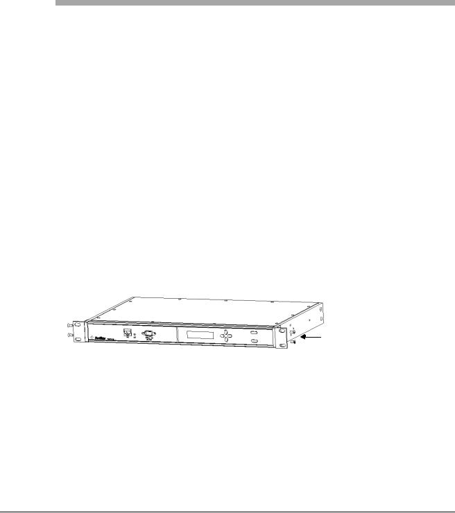
2.2Cabling
Refer to the figures below for TimeVault connector locations. The numbers in the drawing refer to that connector’s position in Table 2-1.
Connect the cables in the order listed in Table 2-1 below. In order to avoid network addressing conflicts, be sure to configure network parameters before connecting the Ethernet cable.
100-240 VAC Power Input (4) |
Chassis Ground (3) ACTS Modem (2) |
12 V Antenna (1) |
||||||
|
|
|
|
|
|
|
|
|
|
|
|
|
|
|
|
|
|
|
|
|
|
|
|
|
|
|
|
|
|
|
|
|
|
|
|
|
|
|
|
|
|
|
|
|
Figure 2-3: TimeVault Back Panel Cabling Illustration (AC Mains)
|
|
–36 to –60 VDC Terminal Strip (4) |
Chassis Ground (3) |
ACTS Modem (2) |
12 V Antenna (1) |
||||
|
|
|
|
|
|
|
|
|
|
|
|
|
|
|
|
|
|
|
|
|
|
|
|
|
|
|
|
|
|
|
|
|
|
|
|
|
|
|
|
|
|
|
|
|
|
|
|
|
|
|
|
|
|
|
|
|
|
|
|
|
|
|
|
|
|
|
|
|
|
Figure 2-4: TimeVault Back Panel Cabling Illustration (–48 VDC)
For the –48 VDC model, connect the rear panel chassis ground to your system ground, the positive connection from the power supply to the “+” of the rear panel terminal strip, and the negative connection from the power supply to the “–” of the rear panel terminal strip.
|
|
|
|
|
|
|
|
|
|
|
|
|
|
|
|
|
|
|
|
|
NET Port (5) |
|
|
|
|
||
Serial Port (6) |
||||||
Figure 2-5: TimeVault Front Panel Cabling Illustration
6000-100Ch2.fm Rev. D |
TimeVault™ User’s Manual |
2-15 |

Chapter 2: Installation and Start-Up |
Cabling |
Table 2-1: TimeVault Cabling Chart
Connection |
Cable Name |
Required / |
Connect Point / |
Label |
Steps |
|
Optional |
Type |
|
|
|
|
|
|
1 |
Sync In |
Required |
Female BNC |
ANTENNA |
|
|
(Be sure your |
Connector for |
|
|
|
antenna supports |
12 V GPS |
|
|
|
12 V) |
Antenna |
|
|
|
|
|
|
2 |
ACTS |
Required for fully |
RJ-11 |
ACTS |
|
Modem |
redundant |
|
|
|
|
operation |
|
|
|
|
|
|
|
3 |
Chassis |
Optional |
Ground screw |
|
|
Ground |
|
|
|
|
|
|
|
|
4 |
Power |
Required |
Power socket |
100–240 V, 1 A |
|
|
|
|
50–60 Hz |
|
|
|
|
or |
|
|
|
|
36–60 VDC POS GND |
|
|
|
|
|
Stop cabling at this point, enter network parameters as per Section 2.5 “NET Port Network Parameters: First Time Configuration” on page 2-28, then resume cabling with Step 5.
5 |
NET |
Required |
RJ-45 |
NET |
|
Interface |
|
10Base-T / |
|
|
|
|
100Base-T |
|
|
|
|
(twisted wire) |
|
|
|
|
|
|
6 |
Serial |
Optional |
RS-232 |
SERIAL I / O |
|
Interface |
|
9-pin D |
RS-232 |
|
|
|
wired as DTE |
|
|
|
|
|
|
2-16 |
TimeVault™ User’s Manual |
6000-100Ch2.fm Rev. D |
Loading...