

Page 1

S100 User Guide
Chapter 1
SyncServer S100 User Guide
Installation, Configuration, and Operation
for the SyncServer S100 - OS Version 1.3
Part #: S100 User Guide, Rev. D, June 2005
Page 2

1
2 S100 User Guide – Rev. D – June 2005
Page 3

Table of Contents
Chapter 1
Introduction and Overview 1
1
Conventions Used 2
Product Details 3
Time Standards 3
Global Positioning System (GPS) 3
Stratum Levels 4
Time Synchronization and Business 4
How the S100 Solves the Problem 5
National Measurement Institutes 5
Special Safety Instructions 6
Lithium Battery Disposal Instructions 6
Electrical Safety Instructions 6
Chapter 2
S100 Technology 7
Overview 7
S100 Product Overview 7
Sources of Time 7
On the Network 7
Web-based Access 8
Time Distribution Model 9
How the S100 Works 9
S100 and Time Distribution 10
S100 and Client Software 10
S100 and NTP v4’s Security Features 10
S100 and the Global Positioning System 11
2
3
5
Chapter 3
Installation and Configuration 13
Overview 13
Getting Up and Running 13
Unpacking Your S100 13
S100 User Guide – Rev. D – June 2005 i
Page 4

1
SyncServer S100
Your CD-ROM 15
Using the Software 16
PuTTY Folder Details 16
PUTTY.EXE 16
PSCP.EXE 16
PSFTP.EXE 17
PLINK.EXE 17
PAGEANT.EXE 17
PUTTYGEN.EXE 18
Installing Your S100 19
Rack Mounting 19
Primary Power Connection 19
Important Safety Instructions! 19
Making All Connections: An Overview 20
Setting Up the Hardware 21
On the S100 Front Panel 21
On the S100 Rear Panel 22
Installing the GPS Antenna 23
Choosing an Antenna Location 23
Installing the GPS antenna 24
Connecting the Rubidium Option 24
Establishing A Serial Connection 24
Setting Up the IP Address 26
Testing Network Functionality 28
Turning Off Your S100 29
How to Acquire Time 30
Logging On 30
Administrator Log-In 31
Next Step 32
The Configuration Wizard 32
Choose Your Time Source 33
GPS 35
NTP 42
Configuring NTP 45
IRIG-B (v.120,122,123) 45
Using SymmTime™ 49
Installing SymmTime 49
To Synchronize SymmTime: 51
Next: Use the Web-Based Interface 51
Chapter 4
The Web-Based Interface 53
Overview 53
Interface: Screen Reference 53
ii S100 User Guide – Rev. D – June 2005
Page 5

Logging In 54
Administrative Interface 54
Admin Interface: Base Menu 55
Administrative Menu: Expanded 56
System Status 57
Timing Configuration 57
NTP Relationships 58
NTP Time Source Test 60
NTP Dialup 60
NTP Restart 61
NTP Status 61
Advanced: ntp.conf 63
Advanced: Keys/Certificates 64
Timing Engine 65
Main Settings 65
Timecode Settings 66
GPS Information 67
GPS Health 67
GPS Signal Strength 68
GPS Time 69
GPS Position 69
Other Information 70
Engine Time 70
Clock Settings 70
Control Settings 71
Model Information 72
Networking 72
TCP/IP 72
ifconfig Output 74
Ping 74
Traceroute 75
Administration 76
Shutdown/Reboot 76
Admin Users 77
Restart Web Interface 77
Time Zone 78
System Log Configuration 78
SNMP Configuration 79
SNMP Edit 79
Alarms 80
Configuration Wizard 80
Logs 81
NTP Log 81
Boot Log 82
System Log 82
Config Log 83
HTTP Log 83
Help 84
1
2
3
5
S100 User Guide – Rev. D – June 2005 iii
Page 6

1
SyncServer S100
SyncServer Help 84
NTPD Help 84
Search NTPD Manual 84
Logging Off 85
Chapter 5
Operations & Time-Protocols 87
S100: Operations and Time Protocols 87
Sysplex Timer 87
Time Protocol (RFC 868) 89
Daytime Protocol (RFC 867) 89
Simple Network Time Protocol (RFC 2030) 90
Network Time Protocol (RFC 1305) 90
NTP Authentication 93
Authentication: NTP v3 93
Authentication: NTP v4 Autokey 94
Public Domain NTP Package 94
Typical NTP Configuration Considerations 94
Other NTP Considerations 95
Clients 95
Basic NTP Configuration 96
Peers 103
Security 103
ACTS Interface: Dial-up 103
ACTS Operation 104
SNMP (Simple Network Management Protocol) 104
Version 1 105
Version 3 106
Chapter 6
Frequently Asked Questions 109
Questions 109
How can we obtain NTP client software to use with the S100? 109
What are the main differences between SNTP and NTP clients? 109
Is there a way to get GPS time instead of UTC time from the S100? 109
What outputs are available on the S100? 109
How does the S100 handle Leap Second? 110
What signal strengths are required by the S100 receiver to start tracking? 110
How do I check versions of the software in the S100? 110
What is the maximum number of computers that can be networked to the
S100? 110
iv S100 User Guide – Rev. D – June 2005
Page 7

How many satellites are necessary for me to operate the S100? 111
How do I know if the satellite signal strength is good? 111
What is the maximum antenna cable length for use with the S100? 111
What are the available antenna cable lengths and antenna requirements? 111
What are some guidelines for correctly cutting the cable, using splitters , and
using cable connectors? 111
How many NTP requests can be processed by the S100 each second? 112
Does the S100 support NTP v4? 112
Can the S100 utilize a certificate from an external CA? 112
How is the interface to the S100 secured? 112
What security functions are provided with the S100? 112
Does the S100 support any functions to restrict user access to NTP service? Can
the S100 set up clients' IP address to be connected? 112
What is the bandwidth utilization (TCP/IP) each time an NTP client gets a time
update from the NTP server? 112
Is NTP v4 compatible with Network Address Translation (NAT) gateways? 113
How does the S100 clock behave when a leap second is introduced? 113
How-to’s and Tips 113
How to install NTP v4 on a UNIX system 114
How to configure an NTP v4 client to connect to an NTP v4 server with the
autokey scheme 114
How to verify NTP v4 autokey client connectivity with an NTP v4 server 114
How to install your S100 114
How to get time using dial-up 114
How to get time using GPS 114
How to install your GPS antenna 115
How to acquire and install SymmTime™ 115
Use the quick “How to” guide 115
How to change the root password 115
How to get information about NTP 116
Solutions 116
The S100 does not respond to ping command 116
The S100 does not respond to NTP queries 116
I cannot establish a serial connection with the S100 116
My S100 won’t track satellites 117
2
3
5
1
Appendix A
S100 Specifications 119
S100 Data Sheet Specifications 119
Pin Descriptions 120
S100 User Guide – Rev. D – June 2005 v
Page 8

Appendix B
SyncServer S100
1
Time Glossary 121
Appendix D
Customer Assistance 137
US Assistance Center 137
Customer Service 137
Technical Support 137
EMEA Assistance Center 137
Customer Service 138
Technical Support 138
Appendix C
Appendix E
Antenna Replacement 141
Index 143
vi S100 User Guide – Rev. D – June 2005
Page 9

Chapter 1
Introduction and Overview
The S100 provides computers and network devices secure synchronization to UTC time
using Network Time Protocol (NTP). The S100 can use the Global Positioning System
(GPS), NIST's Automated Computer Time Service (ACTS), or another NTP server as a time
reference.
Figure 1-1: The S100
1
2
3
This User Guide describes the installation and opera tion of the S100. It is written for network
administrators familiar with network configuration and operations.
The chapters and appendices address topics including:
• Installation, configuration, and operation
• The User Interface
• How the S100 works
• FAQ and Solutions
Here are shortcuts to those sections that answer frequently-asked “how to” or “How do I...?”
questions.
How to... Go here for the answer
Acquire time
Choose and configure your time source
Determine the default User Name and
Password
Get Technical Support
Get time from ACTS dial-up
Get time from GPS
“How to Acquire Time” on page 30
“Choose Your Time Source” on
page 33
“Setting Up the IP Address” on
page 26
“Appendix D” on page 137
“Dialup Settings dialog” on page 38
“GPS” on page 35
5
S100 User Guide – Rev. D – June 2005 1
Page 10

How to... Go here for the answer
SyncServer S100
1
Install the GPS antenna
Install my S100
Install SymmTime
Learn how the S100 works
Establish an IP address and other settings
Set up the optimal operating environment for
my S100
Set up all hardware connections
Synchronize SymmTime
Test for NTP functionality
Use the web-based interface
“Installing the GPS Antenna” on
page 23
“Installing Your S100” on page 19
“Installing SymmTime” on page 49
“How the S100 Works” on page 9
“Setting Up the IP Address” on
page 26
“S100 Specifications” on page 119
“Making All Connections: An
Overview” on page 20
“To Synchronize SymmTime:” on
page 51
“Testing Network Functionality” on
page 28
“The Web-Based Interface” on page 53
Conventions Used
The most common conventions used here are:
Table 1: Type Conventions
Term Definition
Bold Boldface type is used for menu and
Courier The Courier typeface is used to
command names; field, tab, and button
labels; and special terms.
designate file names, folder names,
code, and URLs.
The warning symbol alerts the user to
information that if improperly used could
be harmful to people, equipment, or
data.
2 S100 User Guide – Rev. D – June 2005
Page 11

Product Details
Details about the physical description and operating environment of the S100 are found in
Appendix A, “S100 Specifications” on page 119
Details about S100 operations are in “The Web-Based Interface” on page 53
“Chapter 3” on page 13
Time Standards
The international time standard is called Coordinated Universal Time or, more commonly,
UTC. This standard was agreed upon in 1972 by worldwide representatives within the
International Telecommunications Union; today, the Internet Engineering Task Force (IETF)
sets standards based on the 1972 work. Today UTC is coordinated by the world’s
International Bureau of Weights and Measures, or BIPM. (The designations “UTC” and
“BIPM” were chosen as a compromise among all the countries’ abbreviations for the terms.)
The global availability and precision of UTC time makes it the ideal source of time for Time.
The S100 uses UTC as its time standard.
1
of this User Guide.
, as well as
, and “Operations & Time-Protocols” on page 87.
2
3
Global Positioning System (GPS)
The U.S. Department of Defense Global Positioning System (GPS) is a constellation of
approximately 29 satellites that orbit Earth twice a day. Their orbits are inclined 56 degrees to
the equator . The GPS satellites signals are used by a GPS receiver to precisely determine its
own position and time.
The orbits of these satellites and the offset (relative to international standard time, UTC) of
their on-board Cesium atomic clocks is precisely tracked by the U.S. Air Force control
network. Position and time correction information is uplinked from the ground control stations
and maintained in the satellites in what are termed ephemeris tables, or tables of data that
describe the satellite’s position when compared to specified coordinates. Each satellite
transmission reports the satellite’s current position, GPS time, and the offset of the satellite’s
clock relative to UTC, international standard time.
The “S100 GPS” model uses GPS to obtain time. (The “S100 ACTS” model obtains time by
dialing NIST's Automated Computer Time Service (ACTS).)
5
S100 User Guide – Rev. D – June 2005 3
Page 12

Stratum Levels
SyncServer S100
1
The Internet Engineering Task Force (IETF) established standards for Network Time Protocol
(NTP) in IETF RFC 1305. These hold that the source of time for each server is defined by a
number called its stratum. The highest level is 0; Stratum 0 devices, such as GPS or radio
clocks, are connected to a primary time reference, such as the national atomic clock. Each
level “away” from this primary time reference adds on another number. The Stratum of a
primary server, which gets its time from the GPS system, for example, is assigned as 1.
Devices that get their time from a Stratum 1 primary server through NTP are Stratum 2,
Stratum 3, and so forth. A Stratum 2 or 3 server simultaneously acts as a client, deriving its
time from an NTP process with a Stratum 1 (or 2) Server, and acts as a server for clients
further down the hierarchy.
Here is a summary:
Table Intro-1: Stratum Levels: Summary
Stratum Level Significance
Stratum 0 Connected to a primary time reference, this device—usually a GPS or
radio clock—is synchronized to national standard time.
Stratum 1 A Stratum 1 time server deri ves time from a Stratum 0 time source
Stratum 2...n A Stratum 2 ( and so on) device de rives its tim e from a Stratum 1 server,
or other Stratum 2...n device from NTP.
Obviously, the further away a network is from the primary source, the higher the possibility of
time degradation because of variations in communication paths and the stability of the local
clock.
The S100 can be a Stratum 1 device, as well as Stratum 2 or 3.
Time Synchronization and Business
Reliable time synchronization is essential for doing business today.
Ensuring that all components of a network are synchronized to the global UTC time st andar d
is critical for accurate time stamps, operational logs, and secu rity applications. Many complex
data processing tasks are dependent upon precise event sequences and accurate time
stamping of events.
Not using a dedicated time server can give rise to the following problems:
• Security risks: Users who retrieve time from an outside source, such as the Internet, are
going outside your firewall.
4 S100 User Guide – Rev. D – June 2005
Page 13

• Bandwidth consumption: Synchronizing the time over a WAN (wide area network)
consumes expensive bandwidth and degrades time accuracy (versus synchronizing
over a LAN).
• Lost time: If your network synchronization relies on a time reference outside your
network, your network can be seriously compromised if the one connection to that
outside time reference is lost.
1
How the S100 Solves the Problem
The S100 provides your network with a single unbiased time reference based on one or more
external time references. Should all external time references become unavailable, the S100
uses its own high-performance crystal oscillator to keep time.
The S100, using its internal GPS receiver , operat es as a Stratum 1 time server, with accuracy
to the nearest microsecond relative to UTC as maintained by the U.S. Naval Observatory,
one of the National Measurement Institutes
Time is distributed using the Network Time Protocol (NTP), and between multiple sites. The
result is that with the S100, network users can get time from within your firewall.
Full specifications are found in “S100 Specifications” on page 119
National Measurement Institutes
The S100 synchronizes to UTC. This time standard is maintained by the International Bureau
of Weights and Measures (BIPM). By international agreement, each country’s National
Measurement Institute (NMI) maintains audit records of their synchronization with BIPM UTC,
thus providing verifiable sources of UTC within their countries. NMI clocks are disciplined to
be within nanoseconds of UTC time.
2
3
(NMIs) in the U.S.
.
5
Country Name of NMI Abbreviation
United States National Institute of St andards and Technology NIST
France Laboratoire Primaire du Temps et des Fréquences LPTF
United Kingdom National Physical Laboratory NPL
Japan Communications Research Laboratory CRL
S100 User Guide – Rev. D – June 2005 5
Page 14

1
SyncServer S100
Special Safety Instructions
Lithium Battery Disposal Instructions
Caution: Replace lithium battery only with one of the same
type and ratings. Dispose of the battery in accordance with all
local codes. Contact your local environmental control or disposal agency for details.
Electrical Safety Instructions
Caution: Do not install the modem (phone) cord during an
electrical storm.
Note: minimum 26AWG phone cord is recommended
for added safety.
Note: A minimum 26AWG phone cord is recommended
for added safety.
Note: POWER CORD SELECTION: If your unit is not
provided with a power cord-set, purchase only a Certified cord-set suitable for your location (voltage source)
with a minimum 6A current rating.
6 S100 User Guide – Rev. D – June 2005
Page 15

Chapter 2
S100 Technology
Overview
This chapter gives a review of the S100 technology.
There is additional information in “S100 Specifications” on page 119
1
2
3
.
S100 Product Overview
The S100 network time server synchronizes secure network time. The following sections
describe this technology.
5
Sources of Time
The S100 obtains time from GPS, ACTS, or another S100, and delivers it to computers and
other devices on a network. It acquires UTC (Universal Coordina ted T ime) from GPS signals,
or using ACTS dial-up to the National Institute of Standards and Technology (in the U.S.). If
there are several S100s on your network, only a few S100s need acquire UTC directly. They
can then distribute that time to other S100s.
On the Network
Clients on a network synchronize with a time source using NTP, the Network Time Protocol,
to exchange packets of time. The S100 implements NTP Version 4. This prevents intruders
from spoofing time packets and using NTP to gain access to your systems. Unlike previous
versions, NTP Version 4 implement s asymmetric encryption. This is the same technique used
S100 User Guide – Rev. D – June 2005 7
Page 16

SyncServer S100
by secure web sites to protect credit card numbers and other sensitive information from
unintended interception.
1
The S100 also supports SNMP v1.8 and SNMP v3 (Simple Network Management Protocol)
for easy integration into your existing management hierarchy.
Web-based Access
The S100 management is web-based. Using a standard browser, you can set up and
configure an S100 from any point on the Internet.
See Chapter 3 for more about this web access.
There is a detailed section about this web-based interface in Chapter 4, “The Web-Based
Interface” on page 53.
8 S100 User Guide – Rev. D – June 2005
Page 17

Time Distribution Model
Network time distribution systems use a hierarchical time distribution model, as shown in this
figure:
GPS
Satellites or
NMI Dial-Up
Stratum 0
Stratum 1
Service
Symmetricom
SyncServer
2
3
SyncServers
or Computer
Systems
(NTP Clients)
Stratum 2
1
Computer
Systems
(NTP
Stratum 3
In hierarchical systems, primary time source clocks are Stratum 0 (zero), including GPS
satellites, National Institute of Standards and Technology (NIST) ACTS dial-up service, or
similar national time standards organizations.
The S100 acts as a Stratum 1 time server that derives its time from GPS and distributes this
time over a TCP/IP network using NTP. Strat um 2 NTP clients can distribut e time to S tratum 3
computers.
Clients)
Figure 2-1: The S100 in the Time Distribution Hierarchy
How the S100 Works
The following describes how the S100 acquires and secures time.
5
S100 User Guide – Rev. D – June 2005 9
Page 18

1
More details are found in “Chapter 3” on page 13 and “The Web-Based Interface” on
page 53.
S100 and Time Distribution
Time is distributed over an IP network using Network Time Protocol (NTP), Simple Network
Time Protocol (SNTP), Time Protocol, and Daytime Protocol over TCP/IP.
S100s can be distributed throughout a LAN or intranet. Also, a single GPS antenna is all that
is required to acquire UTC time for an array of S100s, making the network less vulnerable to
damage or attack. (Note: The GPS antenna described in this manual has been replaced as
described in “Appendix E” on page 141
Once the S100 is locked with its time source, it will continuously provide time even if the
timing signal is lost. If the GPS time signal is lost, the NTP message returned by the S100 will
indicate—from the Reference Timesta mp—when it last obtained time updates from the timing
signal.
The S100 maintains the year value as a four-digit number . The S100 maintains time as binary
seconds and has no problem with leap-years and the introduction of leap seconds.
SyncServer S100
.)
S100 and Client Software
Install NTP client software on the client machines in order to synchronize those clients with
S100’s NTP server.
Obtain the SymmTime™ NTP client for Windows at
symmtime.asp.
Details about installing SymmTime are found in “Installing SymmTime” on page 49.
Unix/Linux clients can be synchronized using the public domain NTP daemon or equivalent
NTP client software. If an NTP daemon is not available for your system, you can obtain a
copy of RFC 1305 or 2030 from the Network Information Center (NIC) at
www.ietf.org/rfc/rfc1305.txt, in order to implement an NTP daemon for your system.
S100 and NTP v4’s Security Features
NTP is the de facto standard of communicating time in IP network environments. Developed
at the University of Delaware in the United States, NTP is public domain software. It can
provide time without opening the NTP port and exposing the firewall to possible intrusion. The
S100 supports NTP v4 (Secure NTP), and can support NTP v2 and v3, as well.
The S100 generates keys, which take the form of a file composed of random numerical
sequences. These key files are recognized by the cryptographic authentication components
of NTP. These keys are symmetric, or private (in NTP v3 and v4), and asymmetric or public or
Autokey (NTP v4); Autokey protocol, therefore, can recognize the key files as well. The
contents of the key files include the public/private key pair, a certificate request, a certificate,
and Diffie-Hellman parameters.
http://www.ntp-systems.com/
http://
10 S100 User Guide – Rev. D – June 2005
Page 19

Digitally signed public certificates are required by the Autokey protocol. (See the interface at
“Advanced: Keys/Certificates” on page 64
request (X.509) to a trusted Certificate Authority (CA). The CA can be an outside trust
authority, such as VeriSign, or the device can certify itself. The S100 itself is “self-signed”, or
shipped to you with an authenticated certificate. The S100 CA digitally signs (authenticates)
the request and sends it back, along with the certificate, to the person requesting it.
More details of the NTP protocol and synchronization techniques can be found in the Help file
included with the interface, or at:
•
http://www.ntp.org
http://www.ietf.org/rfc/rfc1305.txt
•
S100 and the Global Positioning System
The Global Positioning System (GPS) receiver in the S100 tracks GPS satellites as they pass
overhead and determines the range of the satellite in relation to its antenna. The GPS
receiver uses the following four properties of the satellite to determine its own position and
derive the time:
• x, or latitude
• y, or longitude
• z, or altitude
• t, or time
.) All of this data goes into your certificate
1
2
3
However, once the GPS receiver has calculated its position, only one satellite is needed to
solve for time (t). This is because the receiver has tracked at least four satellites and has
positioned itself. GPS time is expressed as the number of weeks since midnight, January 6,
1980 (GPS Week) and the number of seconds in the week. These two values are transmitted
as binary integers from the satellites and converted into conventional date or day (UTC T ime)
by the GPS receiver.
5
S100 User Guide – Rev. D – June 2005 11
Page 20

1
SyncServer S100
12 S100 User Guide – Rev. D – June 2005
Page 21

Chapter 3
Installation and Configuration
Overview
Installation, setup, and getting started with the S100 are reviewed in this section.
Symmetricom recommends you review
beginning your installation so that you are already familiar with the references to the interface
once you begin to use it.
Getting Up and Running
This chapter guides you through the following basic steps:
1. Set up the hardware and make all connections (
phone line).
2. Using the serial cable, establish the S100’s IP address.
3. Test for network functionality (ping).
4. Using the web-based interface, choose and configure the time source.
2
before
3
Optional: Install GPS antenna, connect
5
Unpacking Your S100
Unpack and inspect each item in the box. If there is any damage, or any items are missing,
please contact Symmetricom Customer Assistance (see “Appendix D” on page 137
Note: The GPS and bullet antennas and antenna cables described in this manual have been
replaced as described in
The following items should be included:
For the S100-Dial-up/ACTS For the S100-GPS
S100 S100
A/C Power Cord with US-style wall plug A/C Power Cord with US-style wall plug
S100 User Guide – Rev. D – June 2005 13
.
).
Page 22

For the S100-Dial-up/ACTS For the S100-GPS
SyncServer S100
CD with NTP Clients, SymmTime™ software,
User Guide PDF
Six-foot RS-232 Cable Six-foot RS-232 Cable
Phone cord Phone cord
D-BNC Signal Breakout Cable BC11576-1000 D-BNC Signal Breakout Cable BC11576-1000
CD with NTP Clients, SymmTime™ software,
User Guide PDF
Bullet Antenna
Antenna Mast - aluminium mast threaded to
screw into the bottom of antenna
Mounting Bracket Hardware - for attaching
mast to railing
50-foot RG58 (Belden 8240 or equivalent)
cable
14 S100 User Guide – Rev. D – June 2005
Page 23

SyncServer
S100
2
RS -232 Cable
Bullet
Antenna
Figure 3-1: S100 and Accessories
Phone Cord
D-BNC Signal
Breakout C able
For GPS option:
Antenna Cable
CD with
NTP Clients,
SymmTime,
User G uide
Antenna Mast and
Brackets
AC Power
Cord
3
5
Your CD-ROM
The CD does not autoload when inserted into the CD-ROM drive. Use the file browser to view
the contents of the CD. The CD contains: SymmTime, PuTTY, and TermPro23. PuTTY and
TermPro23 are shareware.
• SymmTime synchronizes a Windows-based PC’s clock with the time from an S100 unit
or other NTP server. When executed, a small pop-up containing four clocks appears.
Once installed, visit
downloads.
S100 User Guide – Rev. D – June 2005 15
http://www.ntp-systems.com/symmtime.asp for the latest file
Page 24

• TermPro23.exe is used to install Tera Term terminal emulation software, if desired. The
manual refers to using Hyperterminal. Either will work (as well as any others). This
version supports Win 95, NT 3.51 and 4.0.
• PuTTY is described below.
Using the Software
None of the files in the PuTTY folder must be installed. They are provided in case you re quire
them and do not have them. The SymmTime (click SymmTime200x.exe to launch) file must
be used for synchronization. The TTermPro23 is also optional.
PuTTY Folder Details
PuTTY contains the following optional executable files:
• pageant.exe (Secure Shell [SSH] authentication agent for PuTTY, PSCP, and Plink)
• plink.exe (a command line interface to PuTTY back end)
• pscp.exe (SCP client using command line secure file copy)
SyncServer S100
• psftp.exe (SFTP client for general file transfer session similar to FTP)
• putty.exe (a Telnet and SSH client)
• puttygen.exe (RSA key generation utility)
PUTTY.EXE
is a secure shell client utility that allows you to log into a multi-user computer from another
computer over the network.
The file, Putty.exe, only runs on full Win32 systems (Windows 95, 98, ME, NT, 2000, XP, not
CE).
Most of its data (saved sessions, SSH host keys) is in the Registry at:
WARNING!
Using PuTTY, PSCP, PSFTP, Plink is illegal in
countries where encryption is forbidden. See
http://rechten.kub.nl/koops/cryptolaw/clssum.htm
HKEY_CURRENT_USER\Software\SimonTatham\PuTTY
PSCP.EXE
is a Secure Copy client and a tool for transferring files securely between computers using an
SSH connection. PSCP.EXE is a command line application only. It uses the Windows MS-
16 S100 User Guide – Rev. D – June 2005
Page 25

DOS Prompt (in 95, 98, ME) or the Command Prompt (in NT, 2000). This is available from the
Programs section of your Start Menu.
To start PSCP, add the directory containing PSCP to your PATH environment variable, enter
the following in the console window:
This will only work for the lifetime of that particular console window. To set your PATH more
permanently on Windows NT, use the Environment tab of the System Control Panel. On
Windows 95, 98, and ME, you will need to edit your AUTOEXEC.BAT to include a set
command like the one above.
Further, PSCP.EXE is a command line application, not a GUI application. If you run it without
arguments, it will simply print a help message and terminate. It runs on every SSH server.
PSCP is designed to do a single file transfer operation and immediately terminate.
PSFTP.EXE
is a tool for transferring files securely between computers using an SSH connection.
PSFTP differs from PSCP in the following ways:
• PSFTP uses the new SFTP protocol, which is a feature of SSH 2 only (PSCP will also
• PSFTP allows you to run an interactive file transfer session, much like the Windows FTP
set PATH=C:\path\to\putty\directory;%PATH%
2
3
use this protocol if it can, but there is an SSH 1 equivalent it can fall back to if it canno t).
program.
Y ou can list the contents of directories, browse around the file system, issue multiple get and
put commands, and eventually log out.
PLINK.EXE
is a command line connection tool similar to UNIX SSH. It is mostly used for automated
operations, such as making CVS access a repository on a remote server. Do not use Plink if
you want to run an interactive session in a console window. Plink is a command line
application in the same manner as PSCP.
PAGE AN T.E XE
is for public-key authentication and allows open multiple SSH sessions without having to type
a pass phrase every time. It provides you with the security benefit of never storing a
decrypted private key on disk. Holding your decrypted private keys in Pageant is better than
storing them in disk files. The drawbacks are:
• Windows does not protect pieces of memory from being written to the system swap file. If
Pageant is holding your private keys, it's possible that decrypted private key data may
be written to the system swap file, and an intruder who gained access to your hard disk
might be able to recover that data.
5
S100 User Guide – Rev. D – June 2005 17
Page 26

• Windows prevents programs from accidentally accessing one another's memory space
and it allows programs to access one another's memory space deliberately (e.g.,
debugging). If a virus, trojan, or other malicious program attaches onto your Windows
system while Pageant is running, it could access the memory of the Pageant process,
extract your decrypted authentication keys, and send them back to its master.
Before you run Pageant, you need to have a private key. Use Puttygen.exe to do this. When
you run Pageant, it will put an icon of a “computer wearing a hat” into the System tray. It will
remain there and do nothing until you load a private key into it.
PUTTYGEN.EXE
is a key generator . It generates pairs of public an d private keys to be used with PuTTY, PSCP,
Plink, as well as the PuTTY authentication agent, Pageant. PuTTYgen generates RSA and
DSA keys. Use it as an alternative means of identifying yourself to a login server, instead of
typing a password.
In conventional password authentication, you prove you are who you claim to be by knowing
the correct password. The only way to prove you know the password is to enter it. If the
server has been compromised, an intruder could learn your password.
SyncServer S100
Public key authentication (Puttygen.exe) solves this problem. You generate a key pair,
consisting of a public key—which everybody is allowed to know, and a private key—
which you keep secret and not give to anyone. The private key is able to generate signatures.
A signature created using your private key cannot be forged by anyone unless they have that
key. Anyone who has your public key can verify that a particular signature is genuine.
So you generate a key pair on your own computer, and you copy the public key to the server.
Then, when the server asks you to prove who you are, Putty.exe can generate a signature
using your private key. The server can verify that signature (since it has your public key) and
allow you to log in.
Note: Keep the packing materials for future use. These materials are custo m design ed to
protect the S100 during storage and shipping. Use them if you need to return the unit to
Symmetricom (for Customer Assistance see
“Appendix D” on page 137).
18 S100 User Guide – Rev. D – June 2005
Page 27

Installing Your S100
Install the S100 in a physically secure location with strong physical access controls.
Symmetricom recommends that you read the operating environment requirements and other
specifications in “S100 Specifications” on page 119
Rack Mounting
The S100 is designed for mounting in a standard 19-inch (48.26 cm) rack. It is important to
keep the fan inlet and outlet areas clear to maintain air flow. If the unit is installed in a closed
or multi-unit rack assembly, the operating ambient temperature of the rack environment may
become greater than that of the room. Be sure that the ambient temperature is no higher than
50°C/122°F. Make sure the unit is properly balanced and grounded.
, before starting.
WARNING!
To prevent electrical shock or
injury, DO NOT remove the S100
cover.
Dangerous voltages exist within
this enclosure!
2
3
Primary Power Connection
5
The S100 uses external AC power.
The unit has a power cable with a PH-386, IEC 320-C-13 three-conductor female connector
on the computer end of the cable. The other end of the cable has a NEMA 6-15P grounding
plug (US Standard, 15-amp, 125-volt, straight-blade plug).
Important Safety Instructions!
When using your telephone equipment, basic safety precautions should always be followed
to reduce the risk of fire, electric shock and injury to persons. Do not use this product near
water or in a damp location.
Caution: To reduce the risk of fire, use only No. 26 AWG or larger telecommunication line cord.
S100 User Guide – Rev. D – June 2005 19
Page 28

Making All Connections: An Overview
Use your standard PC workstation to configure the S100.
Refer to the illustrations in this section when you install the S100.
You will need to make a network connection (you may or may not require a hub to do this). It
is suggested you obtain an IP address from your IT dep artment. The Serial cord connect s the
S100 to your computer. Connect the S100 to your network using the network port. Use your
verified IP address in your web browser to reach the S100’s Configuration Wizard online.
SyncServer S100
20 S100 User Guide – Rev. D – June 2005
Page 29

Setting Up the Hardware
On the S100 Front Panel
Figure 3-2: S100 Front Panel Close-up
2
3
Complete the following steps before turning on the power:
1. Connect the 9-pin serial cable from the PC workstation to the S100 serial port. You are
doing this so to configure the S100 using a PC; see “Establishing A Serial Connection”
on page 24 in the next section.
2. Connect the RJ45-terminated Ethernet cable to one or both network ports on the S1 00.
Note: If only one network connection is required, use the left Ethernet port (eth0). The
two USB ports are not functionable on this S100 release.
outputs UTC only.
Sysplex Timer Port: This port
5
S100 User Guide – Rev. D – June 2005 21
Page 30

On the S100 Rear Panel
SyncServer S100
Telephone
cable to wall
J 1
DB15
Connector
Telephone cable
to phone
ANT.
GPS
GPS Antenna
Connector
DB9 Connector
(optional)
Power Panel
Figure 3-3: S100 Rear Panel Close-up
Complete the following steps to complete the S100 installation:
1. Connect the power cable to the S100.
GPS Option: Install GPS Ante nna by connecting it to the GPS Antenna connector shown in
2.
Figure 3-3. Connect the Phone cord to a telephone line.
Note: The GPS antenna described in this manual has been replaced as described in
“Appendix E” on page 141
3. If you are not using a Rubidium oscillator, connect the D-BNC Signal Breakout Cable
(BC1 1576-1000) to the DB15 Connector shown in Figure 3-3. If you are using the S100
with an optional Rubidium oscillator , connect the external rubidium cable (furnishe d with
the Rubidium oscillator) from the DB9 Connector to the DB15 connector (see Figure 3-
3).
Note: The D-BNC Signal Breakout Cable BC11576-1000 has five connectors on it. The three
connectors labelled “Time Code Output”, “Time Code Input”, and “1 PPS Output” are
available for use with on the S100. The connectors labelled “Event Input” and “Heartbeat” are
not applicable for use on the S100.
22 S100 User Guide – Rev. D – June 2005
Page 31

Installing the GPS Antenna
If you are installing an S100 with the GPS option, a bullet antenna is provided. The bullet
antenna provided with the S100 GPS version comes with a weatherproof housing, suitable
for permanent installation in an outdoor location.
Note: The GPS and bullet antennas and cables described in this manual have been
replaced as described in
WARNING: Do not cut the cable to a shorter length. Instead,
bundle any excess cable. Correct antenna cable length—
even if you do not “use it all”—is critical to proper S100
operation. The cable should have a gain within 15dB–25dB.
Choosing an Antenna Location
Global Positioning System (GPS) satellites orbit at an 56 degree inclination to the equator.
The further north you are in the northern hemisphere, the more probable it is that satellites
will be passing to the south of you. And if you are in the southern hemisphere, the satellites
will be passing to the north of you. Please consider this as you install your antenna.
“Appendix E” on page 141.
2
3
The antenna should be located with an unobstructed, clear view of the sky for optimum
tracking conditions. The satellite signals cannot penetrate foliage, or dense wood or metal
structures. The antenna’s operation is not affecte d if it is partially covered with snow, provided
the snow is dry and does not form a continuous ice sheet on the surface. The shape of the
bullet antenna is designed to prevent accumulation of rain, snow , or ice on its surface. (Note:
The bullet antenna described in this manual has been replaced as described in “Appendix
E” on page 141.)
The GPS transmission is a 1.5 GHz (L1Band) spread-spectrum signal. Being spreadspectrum means it is relatively immune to interference. But high energy sources, especially
those with significant in-band energy, can swamp the receiver’s radio frequency (RF)
processing circuitry. In addition, it is difficult to operate GPS at power substations or in close
proximity to high-voltage 60 Hz sources. Symmetricom offers an optional high-gain antenna
that is useful in heavy interference situations. Still, it is best to locate the antenna away from
radiating sources to avoid degradation in antenna performance.
Outdoors
Install the antenna, using the mast and mounting brackets, with a clear view of the sky, and
away from radio frequency interference. It should be mounted vertically, in a location with an
unobstructed view of 30° above the horizon. Be sure to position it at least two meters above
other active receiving antennas, and shield it from transmitting antennas.
5
S100 User Guide – Rev. D – June 2005 23
Page 32

Installing the GPS antenna
Note: The GPS antenna and cable described in this manual have been replaced as described
in “Appendix E” on page 141
1. Slide the antenna mounting pole down over the antenna cable so that the cable passes
through the center of the pole.
2. Take the end of the cable that has passed through the pole and screw the antenna onto
the cable by turning the antenna.
3. Screw the antenna down on the mounting pole by turning the pole.
4. Use the saddle straps to mount the antenna mast in an area where the antenna has an
unobstructed view of 30° above the horizon.
5. After running the cable from the S100 location to the antenna, attach the cable to the
antenna.
Optional: Connect the modem phone line to the card on the back of the S100.
6.
7.
Optional: Connect the chassis ground and install nut (not provided).
SyncServer S100
.
8. On the back panel of the S100, turn on the Power switch. The Power green LED in the
front panel comes on. When the hard drive is active, a red LED light comes on.
Connecting the Rubidium Option
If you are using the optional Rubidium oscillator, the external SS X72 cable needs to be
attached for proper operation. Facing the rear panel of the S100, connect the SS X72 cable
from the DB15 connector to the DB9 connector, forming a single loop. If your unit has no DB9
connector, there is no rubidium in the S100.
Establishing A Serial Connection
This step is necessary to establish the S100’s IP address. The only time you will need to
make a serial connection with the S100 is during setup. Once the S100 has an IP address,
improper shutdown or power failures will not cause the IP address to be lost, also, you will
use the web-based interface for communication.
Note: To test the S100 prior to installation, you will need three Ethernet cables and a hub
(see diagram below). Connect the supplied Serial cable from your computer to the front of
the S100. Connect the S100 and the computer to the hub using two Ethernet cables. You
can perform an off-network test at this point. When you have completed the test, connect
24 S100 User Guide – Rev. D – June 2005
Page 33

the hub directly to the network using the third Ethern et cable an d perf or m an on-n etwork
test.
2
3
Figure 3-4: Connecting the S100
The following instructions assume you are using Windows OS. With your computer turned
on:
1. Use and configure Hyperterminal, click Start->Programs->Accessories-
>Communications>HyperTerminal.
2. The “Connection Description” dialog box appears. In the Name field, enter a name.
In this example, it is
3. Click OK.
4. In the “Connect to” dialog, select the COM Port number you are connected to. In
this example, COM Port 1 is selected.
5. Click OK.
6. In the “COM1 Port Properties” dialog, enter the following Port Settings.
S100.
5
S100 User Guide – Rev. D – June 2005 25
Page 34

SyncServer S100
Figure 3-5: COM Port Properties
* To set the Terminal Type, select File>Properties>Settings.
7. Click OK.
8. In the terminal emulation (e.g., hyperterminal) window, select File->Properties. The
“Properties” dialog opens. Click Settings tab. Verify the Telnet Terminal ID is set
VT100.
at
9. Click OK.
Note: When your Hyperterminal is connected and operational, at the bottom of the win-
dow you should see the following :
Setting Up the IP Address
1. Power on the S100 unit. The Linux system boots. Various bootup data scrolls on the
terminal emulator’s (e.g., Hyperterminal) screen. This may last a few minutes. When
prompted,
symmetricom <Enter>.
2. Additional Linux boot-up data appears. When prompted, enter the Login and Password.
Type each one and press <Enter>.
at the User ID login, type: root <Enter>. At the Password prompt, type:
Note: The following anomaly occurs when using Hyperterminal in WIN 95: “boot: e”
appears at the prompt interrupting the boot proc ess. Use yo ur backspace key to delete the
“e”. Then press <Enter>. This will continue the bootup process. If using Tera Term or other
terminal emulation program, this anomaly may not oc cur. For security purposes, the root,
superuser, password should immediately be changed using the passwd utility. To do
or
this, see
Keep your newly created password in a safe and secure place. If you should lose it, there is
NO PASSWORD RECOVERY capability with the S100. This means that you will have to
send the S100 back to Symmetricom for recovery!
“How to change the root password” on page 115.
syncserv1 login:
Password:
26 S100 User Guide – Rev. D – June 2005
Page 35

Figure 3-6: Login and Command Line
3. A command line appears.
4. Type netconfig and press <Enter>.
5. The Network Config screen pop-up appears, “Would you like to setup networking?” This
screen should appear as follows:
2
3
Figure 3-7: Network Configuration Screen
6. If your screen does not appear this way , check the settings on your Hyperte rminal. Select
Yes <Enter>.
7. Another Network Config screen appears. If you select the DHCP box, setup will
automatically find an IP address. Otherwise, enter your assigned IP address and any
other information in the appropriate area . When completed, press <Enter>.
Note: Most users will use a static IP address. Using the DHCP (Dynamic Host-Configura-
tion Protocol) is an automatic way to obtain an IP address. However, this IP address may
later be reassigned if it is not used for a period of time, depending on your IT network
guidelines.
8. A command line appears. Type reboot <Enter>. The S100 reboots, several Linux bootup screens appear. A similar message should appear (if you selected DHCP)
confirming an IP address (see Figure 3-10
Figure 3-8: DCHP Confirmation Screen
The S100 unit now has an IP address recorded. This IP address will remain even if there is a
sudden power failure or improper shutdown. Make a note of the IP address for future
reference. Use your Password and Login again when requested as in Step 2 (under Setting
up the IP Address). Jot down the IP address.
also):
5
S100 User Guide – Rev. D – June 2005 27
Page 36

Testing Network Functionality
To ensure that your network is functioning correctly, check to see if the S100 is on the
network.
First, check the Ethernet connection between the client computer and the S100:
1. Call up the client computer’s command prompt. Use the Windows MS-DOS command
prompt. At the command line, type: IPCONFIG<Enter>. Your computer’s IP address
appears (see A).
A
B
SyncServer S100
C
Figure 3-9: IPCONFIG and PING Screen
Note: In Win95, type WINIPCFG at the command line in Step 1.
At the command prompt (See Figure 3-9), type a ping command to verify that the S100 is
visible on the network. Use the IP address for the S100. For example:
ping xxx.xxx.xxx.xxx (where xxx = the IP address of the S100).
2. Press <Enter>. The message shown in Figure 3-9 indicates the ping command was
successful. Four packets were sent and none were lost. An unsuccessful ping re sults in
packets lost and a Timed Out message.
If there is an affirmative response, the S100 is visible to the network.
Note: If there is no response, then troubleshoot and fix the connection problem before
proceeding with the next steps. Problems may include physical network connections or IP
addresses.
28 S100 User Guide – Rev. D – June 2005
Page 37

3. Now, verify the S100’s IP address. At the Unix command prompt, at the command line
(Figure 3-6
4. Open your web browser, enter the IP address in the browser Address field and
press<Enter>. The Configuration Wizard link appears. Use the Wizard to complete the
S100 configuration process.
Turning Off Your S100
Normal
), type IFCONFIG and press <Enter>. The following appears (Figure 3-10).
2
Figure 3-10: Linux IP Confirmation Screen
3
If you have configured the unit correctly and it is running normally, select (Administrative
Menu) Administration>Shutdown/Reboot from the S100’s web interface. The following screen
appears:
5
Figure 3-11 : S100 Shutdown Screen
If you are using SSH or TTY, at the prompt type: shutdown -h now<Enter>.
S100 User Guide – Rev. D – June 2005 29
Page 38

How to Acquire Time
With the S100, you can choose your source of secure time.
Each of the time references described in this section is configured using the web-based
interface’s Configuration Wizard.
First, log on.
Logging On
In your browser , enter the IP address of the S100 (use this format: “http://ipaddre ss”). Add the
S100 home page to your ‘Favorites’ list for future convenience. If the link/icon is not present,
in your browser address window, enter the S100 IP address <Enter>.
SyncServer S100
On your first log-in, the first screen you see is the System Status
Figure 3-12: Initial System Status
The System Status screen gives you the status of the S100’s Timing, Uptime, and
Versions.
screen.
The color of the box on the top left side of the screen is your guide. It follows the traffic light
convention:
• Green = Normal Operation: The S100 is up and running with the correct time.
• Amber = Unsatisfactory: System not yet ready to issue time.
• Red = Unsatisfactory: Some settings still need attention before secure time can be
issued.
Note: Log-ins after this first log-in will bring you to the last screen you accessed in your
most recent session.
30 S100 User Guide – Rev. D – June 2005
Page 39

Administrator Log-In
On the System St a tus Screen, click the Administrator Log-In link. Af ter th e security alert,
the following dialog is displayed.
2
Figure 3-13: Logging In
Enter the default user name,
recommend you change these settings as soon as possible.
(You may log off by clicking Log Out at the top of each screen in the interface. More about
logging off can be found in “Logging Off” on page 85
admin, and default password, symmetricom. We strongly
.)
3
System Status: Logged In
Once logged in, you see the System St atus screen ag ain except now it has more information.
Configuration Wizard
5
Figure 3-14: Full System St atus
In Versions, this information refers to the current software in the S100. In the NTP Host
Reachability , this example shows that the IP address was accessed eight times and provides
additional details.
S100 User Guide – Rev. D – June 2005 31
Page 40

Next Step
If this is your first log-in, your next step is to select the Configuration Wizard link at the top
of the System Status page (see Figure 3-14
If you have logged in before and have already configured your S100, skip the Configuration
Wizard and instead choose the item you want from the Administrative Index in the left pane.
Details are then provided in the right window pane. If you have established the S100's IP
address, type it in the browser's Address field and press <Enter>. The browser displays the
screen in Figure 3-15
SyncServer S100
).
.
Figure 3-15: Configuration Wizard: Choose Primary Time Source
Note: The Configuration Wizard is the most convenient way to configure the S100 .
The Configuration Wizard
Using your browser, follow this easy-to-direct sequence of dialogs to configure the S100’s
source of time. You will need the wizard only once, unless you change the time source for the
S100.
Every screen in the wizard lets you start over, reset, or (for a screen in a sequence) go back
to the previous screen.
Note: When within the Configuration Wizard, do not use your browser’s back button. Use
the Wizard’s back button instead:
Use the Reset button to clear the fields of previously typed information.
32 S100 User Guide – Rev. D – June 2005
Page 41

Choose Your Time Source
The first dialog in the Configuration Wizard asks you to choose the source of time.
2
Figure 3-16: Choose Your Time Source
The choices are:
• Global Positioning System (GPS)
• Dial-up (
• Network Time Protocol (NTP)
• IRIG-B
Figure 3-17 shows the screen flow after choosing the time source option you prefer.
to NIST's Automated Computer Time Service (ACTS))
Warning: If you've already configured your timing engine, the Configuration
Wizard will remove all of that configuration. This may be considered
desirable; please be sure that this is what you want to do.
3
5
S100 User Guide – Rev. D – June 2005 33
Page 42

SyncServer S100
Figure 3-17: Configuring the S100 Time Source
Beginning on the following pages, you will be walked through each of the various
configuration screens used in the Wizard. Most information is self-explanatory. Regardless of
the time source chosen for configuration, the Wizard uses a common set of screens and only
the specific information relating to the time source chosen may be different on any particular
screen.
34 S100 User Guide – Rev. D – June 2005
Page 43

GPS
2
Figure 3-18: Dialup Backup
If you choose GPS (see Figure 3-16) and click Next, the Dialup Backup dialog is
displayed. If you wish to use dial-up as a backup time source to GPS, click the checkbox ne xt
to Use dialup as backup to GPS, then click the Next button.
If you do not want to back up your GPS time source with dial-up, leave the checkbox
unselected, and click Next, which will open the System Information dialog (see Figure 3-
20).
3
If you check Use dialup as backup for GPS, this Dialup Settings dialog is displayed. In
Options, if you wish to use ATDP (pulse dialing), check the box, otherwise the S100 uses
standard ATDT (dial tone) dialing.
5
Figure 3-19: Dial-up Settings
In the Modem Phone Number field, enter the NIST phone number preceded by any
prefixes that might be required to reach those numbers. A “9,” (nine comma) prefix gets an
outside line from an office phone; the comma introduces a one-second delay before the
remaining numbers are dialed. The “1” prefix is required for long distance dialing in the US.
S100 User Guide – Rev. D – June 2005 35
Page 44

Then click Next for the System Information dialog.
Figure 3-20: System Information
SyncServer S100
• Admin e-mail, for the administrator of the S100. After a test is conducted, this email
address receives the notice.
• Mail forwarder, or the SMTP server
• Host name
• System (S100) location
Confirm the data that is in the fields. If it is not accurate, change it to the correct information.
Click Next.
Note: All the fields are optional. A unit can be configured and tested with all the fields
blank.
36 S100 User Guide – Rev. D – June 2005
Page 45

System Tests Dialog
Figure 3-21: System Testing options
You can skip the test by clicking Finish, or initiate the test by clicking Test Now.
2
3
The default is to test all the services, so unless you un-check them, they all will be tested. If
you do not use dial-up as backup, it will not be listed here nor will it be tested. Initiat e the test
by clicking Test Now.
Test Results dialog
5
Figure 3-22: Test Results shown
This displays the results of your test. This tells you if the S100’s GPS receiver is functioning
properly. In this example, it is. However, failed tests are also shown.
S100 User Guide – Rev. D – June 2005 37
Page 46

SyncServer S100
There is no output to the “Mail test” field. That is because mail is tested by sending an e-mail
to the address that was not provided earlier.
Click Finish.
Setup Complete dialog
Figure 3-23: Your GPS set-up is complete
This screen verifies your configuration of the S100:
• Its time source
• Modem phone number (if you designated dial-up as the backup source for time)
• Host name and System location
• Administrator e-mail
Dialup Settings dialog
When using dial-up, the time reference is coming from an analog phone line through the b uiltin modem. Automated Computer Time System (ACTS) is maintained by NIST.
In the US, use either of the following phone numbers to access time:
• Colorado: (303) 494-4774
• Hawaii: (808) 335-4721
Outside the US, connect with your local measurement institute.
38 S100 User Guide – Rev. D – June 2005
Page 47

2
Figure 3-24: Dial-up Settings
If you choose the Dialup radio button and click Next, the Dialup Settings dialog is
displayed.
In the field, enter or paste your modem phone number.
Then click Next for the System Information dialog.
System Information dialog
3
5
Figure 3-25: System Information fields
This shows:
• Admin e-mail, for the administrator of the S100
• Admin Password
• Mail forwarder, or the SMTP server
S100 User Guide – Rev. D – June 2005 39
Page 48

SyncServer S100
• Host name
• System (S100) location
Confirm the data that is in the fields. If it is not accurate, change it to the correct information.
Click Next.
System Tests dialog
Figure 3-26: System Testing options
You can skip the test by clicking Finish, or initiate the test by clicking Test Now.
The default is to test all the designated services, so Dialup and E-Mail, unless you un-
check them, will be tested.
To initiate the test, click Test Now.
40 S100 User Guide – Rev. D – June 2005
Page 49

Test Results dialog
2
Figure 3-27: Test Results shown
3
This screen tells you if the dial-up time source for your S100 is functioning properly. In this
example, failed tests are shown.
There is no output to the “Mail test” field. That is because mail is tested by sending an e-mail
to the address that you indicated earlier.
Click Finish.
Setup Complete dialog
Figure 3-28: Your Dial-up set-up is complete
This screen verifies your configuration of the S100:
• Its time source
• Modem phone number
• Host name
5
• System location
• Administrator e-mail
S100 User Guide – Rev. D – June 2005 41
Page 50

NTP
SyncServer S100
ntp1.symmetricom.com
Figure 3-29: Defining Your NTP Settings
You can also acquire time through other NTP servers and S100s.
Note: If you have not configured DNS, use IP addresses rather than hostnames.
Choose the NTP radio button (see Figure 3-16) and click Next.
The Network Time Protocol Settings dialog (Figure 3-29
one (or more) NTP servers or peers.
NTP v4’s Autokey requires digitally signed certificates. For more about the Autokey protocol,
see “S100 and NTP v4’s Security Features” on page 10
Then click Next.
) appears. On this screen, name
.
42 S100 User Guide – Rev. D – June 2005
Page 51

System Information dialog
Figure 3-30: System Information fields
2
3
The System Information dialog shows you:
• Admin e-mail, for the administrator of the S100
• Mail forwarder, or the SMTP server
• Host name
• System (S100) location
Confirm the data that is in the fields. If it is not accurate, change it to the correct information.
Click Next.
5
S100 User Guide – Rev. D – June 2005 43
Page 52

System Tests dialog
SyncServer S100
Figure 3-31: System Te stin g optio ns
You can skip the test by clicking Finish, or initiate the test by clicking Test Now.
The default is to test all the services, so NTP and E-Mail, unless you un-check them, will be
tested.
Click Test Now.
Test Results dialog
Figure 3-32: Test Results shown
This screen tells you if the NTP time source for your S100 is functioning properly or if there is
a test problem.
44 S100 User Guide – Rev. D – June 2005
Page 53

There is no output to the “Mail test” field. That is because mail is tested by sending an e-mail
to the address that you indicated earlier.
Click Finish.
Setup Complete dialog
2
3
Figure 3-33: Your set-up is complete
This screen verifies your configuration of the S100:
• Its time source
• Host name
• System location
• Administrator e-mail
Configuring NTP
To configure NTP, use the NTP Relationships dialog (See “NTP Relationships” on
page 58). Use the dialog to view the NTP status and create the NTP associations.
IRIG-B (v.120,122,123)
Both the D-BNC Signal Breakout Cable and the optional Rubidium oscillator cable provide a
Timecode Input connector. To use IRIG time code as a reference, connect the IRIG signal to
the Timecode Input connector, select IRIG-B (see Figure 3-16
If you wish to use dial-up as a backup time source to GPS, click the checkbox next to Use
dialup for backup to IRIG-B, then the Next button.
If you do not want to back up your IRIG with dial-up, leave the checkbox unselected, and click
Next.
5
), and click Next.
S100 User Guide – Rev. D – June 2005 45
Page 54

SyncServer S100
Dialup Backup dialog
Figure 3-34: Dial-up Settings
If you check Use dialup as backup for IRIG-B, a similar Dialup Settings dialog is
displayed (see Figure 3-24
).
In the field, enter or paste in your modem phone number. Then click Next.
A screen similar to Figure 3-35
System Information dialog
now appears.
Figure 3-35: System Information fields
This shows:
• Admin e-mail, for the administrator of the S100
• Mail forwarder, or the SMTP server
46 S100 User Guide – Rev. D – June 2005
Page 55

• Host name
• System (S100) location
Confirm the data that is in the fields. If it is not accurate, change it to the correct information.
Click Next.
System Tests dialog
2
3
Figure 3-36: System Testing options
You can skip the test by clicking Finish, or initiate the test by clicking Test Now.
The default is to test all the services, so unless you un-check them, they all will be tested. If
you do not use dial-up as backup, it will not be listed here nor will it be tested.
S100 User Guide – Rev. D – June 2005 47
5
Page 56

SyncServer S100
Test Results dialog
Figure 3-37: Test Results shown
This screen shows whether the IRIG-B for your S100 failed or passed. In this example, the
IRIG-B failed.
There is no output to the “Mail test” field as no addresses had been provided in the System
Information dialog (Figure 3-35
).
Click Finish.
Setup Complete dialog
Figure 3-38: Your IRIG set-up is complete
This screen verifies your configuration of the S100:
• Its time source
• Modem phone number (if you designated dial-up as the backup source for time)
• Host name
• System location
• Administrator e-mail
48 S100 User Guide – Rev. D – June 2005
Page 57

Using SymmTime™
Next, you need to install client software to test NTP (Windows installation).
The SymmTime utility is a handy way of doing this. It keeps accurate time on your client
Windows computer.
Figure 3-39: SymmTime™ Utility and Clock Display
Use SymmTime200x.exe to launch SymmTime on your PC. When executed from the CDROM, a small pop-up containing four clocks appears. Once installed, visit
systems.com/symmtime.asp and download the latest updated files.
Installing SymmTime
2
http://www.ntp-
3
1. On the client computer’s hard drive, create a separate directory for SymmTime.
2. Copy the
3. Double-click
4. Configure the clocks as you desire using the Build tool (select the hammer in the lower
right corner, the following appears).
SymmTime200x.exe file from the utility disk into this directory.
Symmtime.exe. This will install the program onto your computer.
5
S100 User Guide – Rev. D – June 2005 49
Page 58

5. Right-click the displayed clocks for the menu and select Sync Servers
6. The following screen appears. Click Add Server.
SyncServer S100
7. New Server dialog box, enter the IP address and location of the S100. Click OK. The IP
address you use will be the one obtained in the setup of the S100.
50 S100 User Guide – Rev. D – June 2005
Page 59

8. The IP is added to the Active Servers window. Click OK. The IP address is listed under
Active Servers.
To Synchronize SymmTime:
1. Right-click anywhere on the clocks. Select Sync Status from the menu to tell your
computer to automatically get time from the S100. A similar screen will appear.
2
3
5
2. Click Sync Now. If you receive a no response, it is because you have not yet configured
the S100; configure it now. An affirmative response confirms you have configured the
S100.
Next: Use the Web-Based Interface
Now that you have established the S100, configured your time source, and installed your
client software, you can use the web-based interface to manage S100 operations. See
Chapter 4 for a complete description.
S100 User Guide – Rev. D – June 2005 51
Page 60

SyncServer S100
52 S100 User Guide – Rev. D – June 2005
Page 61

Chapter 4
The Web-Based Interface
Overview
The following is a description of the web-based software interface that you use to manage the
S100.
This material is designed to be a reference for you as you use the S100. It also describes
some of the procedures that will help you begin using the S100.
Symmetricom recommends you review this section before beginning the permanent
installation of the S100, so that you will be familiar with it when you need to use it.
For detailed information about NTP (Network Time Protocol), use the NTPD Help link (see
“NTPD Help” on page 84
Distribution document (source: University of Delaware).
Additional information is available at
) embedded in the S100’s web interface to review the NTP
Interface: Screen Reference
The S100 management interface has been designed with ease of use in mind. As a result,
you access the management interface S100 through any web browser. This section
describes the screens used in the interface, including their functions. It supplies some
procedural instructions, as well.
2
3
http://www.ntp.org/.
5
Each dialog or screen, except in the Configuration Wizard, lets you refresh that screen or
open a new window, and all will let you log out.
For security reasons, the interface will time out after 30 minutes if there is no activity.
S100 User Guide – Rev. D – June 2005 53
Page 62

Logging In
Using your browser , the following dialog is displayed once you enter the S100’ s IP address or
click the link to or icon for the S100.
SyncServer S100
Figure 4-1: Logging In
Enter the default user name,
Assuming this is the first time you have logged in, you will see the System St atus screen (see
“System Status” on page 57
Log-ins after this first log-in will bring you to the last screen you accessed in your most recent
session.
Administrative Interface
This is the main tool for administering the S100.
If you click Refresh at the top of any screen, it will remove any confirmation or error
messages on the screen.
If you click New Window at the top of any screen, it opens a second browser window without
the admin menu.
admin, and default password, symmetricom.
).
54 S100 User Guide – Rev. D – June 2005
Page 63

Admin Interface: Base Menu
The first thing you see on the left of your screen is the base Administrative (Admin)
Menu. This is the starting point for administration tasks on the S100. Click “+” to expand the
sub-menu.
2
Figure 4-2: Administrative Interface: Base Menu
3
5
S100 User Guide – Rev. D – June 2005 55
Page 64

Administrative Menu: Expanded
Expanding each item on the base menu shows you all the available options. Click Collapse
(at the bottom of the menu) to revert to the base version of the menu.
SyncServer S100
Figure 4-3: Interface Admin Menu, expanded
56 S100 User Guide – Rev. D – June 2005
Page 65

System Status
Clicking this item, you will quickly see the status of the S100.
2
3
Figure 4-4: Checking the Status
The color of the box on the left side of the page is your guide. It follows the traffic light
convention:
• Green = Normal Operation: the S100 is up and running with the correct time
• Amber = Unsatisfactory: Some settings still need attention before secure time can be
issued
• Red = Unsatisfactory: System not yet ready to issue time
Timing Configuration
These menu options let you manage NTP, the heart of the S100 system. For more details on
each of the NTP terms used here, see “NTPD Help” on page 84
5
.
S100 User Guide – Rev. D – June 2005 57
Page 66

NTP Relationships
Use this option to configure NTP
.
SyncServer S100
Figure 4-5: Configuring New Clients and Servers
Define the relationships between and among this host and other hosts.
For more details, see “NTPD Help” on page 84
web interface.
In the NTP Associations panel of this screen you see the configuration of the network that
you are putting the S100 on. These are all the devices from which the S100 can get time.
They are named as server or peer, depending on their relationship to the S100.
In this section, clicking Reset clears any data you’ve just added, and clicking Remove and
Restart NTP deletes the checked host(s).
The Add New Relationships panel lets you add a host to your configuration. Next to each
parameter, enter the values for the clients you are adding to the configuration:
Role - The host you add can serve in any one of the following roles:
• Peer
58 S100 User Guide – Rev. D – June 2005
or click HTPD Help embedded in the S100
Page 67

• Server
• Broadcast
• Manycast Client
• Broadcast Client
• Manycast Server
• Multicast Client
Address - Enter the IP address or host name for the host you are adding.
Dialup, timing engine, and Set timing engine mode links - Use these links to populate the
address field appropriately.
Dialup Phone Number - Enter the modem phone number you will be using. Enter a 9, (nine
comma) if required to get an outside line. (The comma introduces a one second delay, which
gives time for the outside dial tone to become available.)
Prefer - This marks the server as “preferred”, meaning this server, of all the correctly
operating hosts and if all things are equal, will be the host chosen for synchronization.
2
3
Key - All packets sent to and received from the server or peer will include authentication
fields encrypted using the specified key.
• None: The default, no encryption field.
• Key= : This is the index of the key in the keystore.
• Autokey: All packets sent to and received from the server or peer include authentication
fields encrypted using the autokey scheme. (NTP v4)
Burst - Data grouped for transmission, in the following ways:
• N/A: If you choose this option, the Burst command will not be executed.
• Burst: Selecting this option tells the system that when the server is reachable, send
eight packets instead of one.
• iBurst: Selecting this op tion tells the system that when the server is not reachable, send
eight packets and keep trying every 16 seconds.
Minimum Poll Interval - Indicate in seconds the smallest measure of time in which you want
the S100 to check the network hosts’ time. If you enter nothing here, the S100 will use the
default, 0:01:04 seconds.
5
Maximum Poll Interval - Indicate in seconds the largest measure of time in which you want
the S100 to check the network hosts’ time. If you enter nothing here, the S100 will use the
default, 0:17:04 seconds.
Time to Live - Data in the Internet Protocol that specifies how many more hop s a packet can
travel before being discarded or returned, here entered in the form of whole numbers.
Version - These are Default, 1, 2, 3, or 4.
Clicking Reset clears the data you’ve just entered.
Clicking Add and Restart NTP adds the data you’ve just entered and restarts NTP.
When you are finished with the addition of any new clients, they will display in the NTP
Relationships panel (see “NTP Relationships” on page 58
S100 User Guide – Rev. D – June 2005 59
) at the top of the screen.
Page 68

NTP Time Source Test
The NTP Server Test dialog lets you test the servers you designated in the NTP
Relationships panel (see “NTP Relationships” on page 58
Host -
• All
• 127.127.40.0 (onboard GPS/IRIG reference clock driver)
• 127.127.18.3 (NIST ACTS reference clock driver)
SyncServer S100
.
Figure 4-6: Testing the NTP Time Source
• localhost
Options - Use the checkbox to enable Verbose Output.
NTP Dialup
In the following dialog, enter or paste in your modem phone number.
Then click Submit.
Figure 4-7: NTP Dialup
60 S100 User Guide – Rev. D – June 2005
Page 69

NTP Restart
Here, you can restart the NTP daemon, for troubleshooting purposes only.
However, please note the following warning:
NTP Status
This screen gives you the following information:
Figure 4-8: Restart NTP
Warnin g!
It can take NTP a significant
period of time to go through its
processes. If you choose to
restart, you will be required to
reset your time source.
2
3
5
Figure 4-9: Snapshot of NTP Status
Reference Time - This is the last time it synced.
System Peer - This tells you which NTP server the S100 is synced to.
System Peer Mode - This tells you what the S100 is—client or otherwise—to the NTP server
it is synced to.
S100 User Guide – Rev. D – June 2005 61
Page 70

SyncServer S100
Leap Indicator - This is a two-bit code warning of an impending leap second. The numbers
mean:
00 = no warning
01 = the last minute has 61 seconds
10 = the last minute has 59 seconds
11 = alarm condition (clock not synchronized)
Stratum - This is the stratum level of the S100.
Precision - This is an eight-bit signed integer indicating the precision of the local clock, in
seconds to the nearest power of two. The range is -6 to -18.
Root Distance, or root delay - This is a signed fixed-point number indicating the total round-
trip delay to the primary reference source at the root of the synchronization subnet, in
seconds. It can be expressed as either a positive or negative number.
Root Dispersion - A 32-bit unsigned fixed point number indicating the maximum error
relative to the primary reference source, in seconds (milliseconds).
Reference ID - A 4-byte code indicating the reference source. If the reference source is
stratum 0, this string will identify the type of source (GPS or dial-up, for example). If the
source is stratum 1 or higher, this 4-byte code will contain the IP address of the reference
source.
Reference Time - The local time at which the local clock was last set or corrected, in a 64-bit
time-stamp format.
System Flags - These are various flags that can be enabled or disabled using the
configuration commands.
Jitter - Distortion of a signal caused by some weakness in synchronization, here shown in
seconds (milliseconds).
Stability - This is the residual frequency error remaining after the system frequency
correction is applied. Used most often in maintenance, the value starts as high as 500 ppm
but settles into the .01 to 0.1 ppm range.
Broadcastdelay - This shows the default broadcast delay.
authdelay - This is the default authentication delay.NTP Advanced Configuration
Here you will find advanced configuration features of NTP. Y ou probably won’t need to access
these, but they are here if you need to edit the configuration.
62 S100 User Guide – Rev. D – June 2005
Page 71

Advanced: ntp.conf
The following dialog is only for those with advanced knowledge of NTP.
The dialog in Figure 4-10 displays the NTP configuration file. It allows you to edit the config
text file.
2
3
Figure 4-10: Viewing the NTP Configuration File
If you need help with the NTP config file, click the NTP Config uration Help link near the top of
the screen, and you will be directed to NTP Help. Additional information about NTP is
available is available at www.ntp.org
.
Warnin g!
If you improperly configure the
ntp.conf, you will render the S100
unable to sync to any time source.
Be certain you know NTP well
enough to do this.
5
S100 User Guide – Rev. D – June 2005 63
Page 72

Advanced: Keys/Certificates
Use this NTP Keys/Certificates dialog to obtain a digital certificate that verifies the identity o f
the S100.
SyncServer S100
Figure 4-11: Obtaining and Generating Ke ys
and Certificates
Working from top to bottom:
Generate Keys - Select the key algorithm and hash algorithm you wish to use:
• RSA + MD5
• RSA + SHA1
• DSA + SHA1
DSA + SHA1 is the default.
New Random MD5 Keys - Select this checkbox to generate random MD5 keys.
Then click Generate.
The screen refreshes and a “keys generated” message displays in the upper left corner.
Next to the Certificate Request field, click Request to issue a certificate request. A
confirmation dialog will prompt you to tell the system where you want the certificate; respond
to the prompt.
If you choose Upload Certificate, browse to the certificate request, as sent to you by the
Certificate Authority, or enter its name. Then click Upload.
64 S100 User Guide – Rev. D – June 2005
Page 73

Alternatively, you can use Paste Certificate to copy and paste the certificate from the
certreq.jsp file into this field. Open the certreq.jsp file using a text editor (e.g., Notepad)
and copy the contents. The certificate should be base 64 encoded. Paste the contents in the
Paste Certificate field here, then click Submit.
The S100 is self-signed, thus it can verify your certificate.
For more about how the S100 uses NTP keys and certificates, see “S100 and NTP v4’s
Security Features” on page 10.
Timing Engine
This section of the interface lets you view various aspects of the Symmetricom bc635/637
PCI board—the timing engine of the S100.
Main Settings
The timing engine mode choices you see in the drop-down list box are:
2
3
5
Figure 4-12: Timing Engine Main Settings
• GPS is the default, which obtains the time from GPS receiver and antenna.
• IRIG, which obtains the time from the IRIG time code input. (Note: IRIG time code
doesn’t include the year with its time information. Be sure to enter the year in the Year
field.)
• Free Running means there is no external timing source used, that the time is set
manually
• One Pulse Per Second, or 1PPS, syncs the oscillator to a user-supplied 1PPS
S100 User Guide – Rev. D – June 2005 65
Page 74

SyncServer S100
• Real-Time Clock, or RTC, synchronizes the oscillator to the 1PPS signal from the
timing engine itself
Mode - How time is being acquired.
Time Format - The timing engine uses Binary code time.
Year - Set the year here. (No te: You must enter the year if you are using IRIG as the primary
reference source).
Local Offset - Allowed values are -16 through +16, and can include half-hour offsets.
Propagation Delay - If there is any propagation delay from the reference source, the timing
engine will adjust for it. Values range from -9999999 to +9999999.
Current Leap Seconds - This figure accounts for the local offset.
Scheduled Leap Event Time - This is a 32-bit binary value corresponding to the number of
seconds elapsed since 0 hour January 1, 1970 UTC.
Scheduled Leap Event Flag - This will alert you to an upcoming leap event.
GPS Time Format - UTC is the default.
IEEE Daylight Savings Flag - This alerts you to an upcoming Daylight Savings Ti me event.
Timecode Settings
Code type choices in the drop-down list box are:
• IRIG-A
• IRIG-B
• IEEE 1344
• NASA 36
Code Type - This identifies the time code in setting.
Figure 4-13: Timecode Settings
Modulation Type - The type associated with the time code signal:
• AM, for amplitude modulated
• DC, for direct current level shift, or digital IRIG
66 S100 User Guide – Rev. D – June 2005
Page 75

The default modulation envelope is AM.
Time Code Settings - This confirms the settings:
• Time Code = The time code
• Code Modulation = The modulation type associated with the time code signal
• Time Code Out = The time code
• Genera tor T ime Of fset = This shows any of fset to the time code sign al being produced by
the timing engine.
Clicking Reset lets you clear any data you’ve entered, and Submit implements changes
you have made.
GPS Information
This section of the admin menu appears only if you have the GPS option on the S100.
The following items give details on GPS activity:
GPS Health
This screen updates the signal status. This example shows a normal screen.
in setting
out setting
2
3
5
Figure 4-14: GPS Health Status
The error codes are encoded into individual bits within the byte. The bit positions and their
meanings are shown below.
Bit Position Meaning if bit value = 1
0 Battery back-up failed (1)(4)
1 Signal processor error (1)
2 Alignment error, channel or chip 1 (1)
3 Alignment error, channel or chip 2 (1)
4 Antenna feed line fault (2)
5 Excessive ref freq. error (3)
S100 User Guide – Rev. D – June 2005 67
Page 76

6 (Unused)
7 (MSB) (Unused)
Notes:
(1) After this error is detected, its bit remains set until the GPS receiver is reset.
(2) This bit follows the current status of the antenna feed line fault-detection circuitry. Since
GPS receiver has an integral antenna assembly, this information of little import; it is only
shown for the sake of completeness, being important for sensors with separate antennas.
(3) This bit is ‘1’ if the last computed reference frequency error indicated that the reference
oscillator is out of tolerance. (Packet 2D requests the oscillator offset and packet 4D returns
the oscillator offset to the user.)
(4) this bit is always set as the GPS receiver battery backup is not installed.
GPS Signal Strength
Here, the signal strength are displayed.
SyncServer S100
Figure 4-15: GPS Signal Streng th
The data is for the satellites that are currently being tracked:
• The satellite number
• The signal level for each satellite
68 S100 User Guide – Rev. D – June 2005
Page 77

GPS Time
GPS time is noted here.
Seconds of Week - This is expressed in the number of seconds since January 6, 198 0 (GPS
Week).
2
Figure 4-16: GPS Time
GPS Week Number -This is expressed in the number of weeks since January 6, 1980.
GPS/UTC Offset - Currently this is 13 seconds.
GPS Position
This screen shows you the calculated coordinates of the gps antenna.
X Coordinate = Latitude
Y Coordinate = Longitude
3
5
Figure 4-17: GPS Position
Z Coordinate = Altitude
Time-of-fix = Time
For more about GPS position, see Chapter 2, “S100 and the Global Positioning System”
on page 11.
Note: The GPS antenna described in this manual has been replaced as described in
“Appendix E” on page 141
S100 User Guide – Rev. D – June 2005 69
.
Page 78

Other Information
The following screens give additional information about the S100.
Engine Time
The engine time is read directly from the timing engine.
Clock Settings
SyncServer S100
Figure 4-18: Timing Engine Time
The clock settings here are:
Figure 4-19: Clock Settings
Oscillator - This is internal to the timing engine.
DAC Value - A 16-bit Digital Analog Converter is used to set the frequency on the oscillator.
The value here shows a rate match between the hardware clock frequency and the selected
time reference source.
Jam Control - “Jam” refers to jam synchronization. This controls whether or not the
software may “jam” the clock circuitry if a phase discontinuity of greater than 1 millisecond is
found.
Battery Status - The timing engine’s battery status is noted here.
Clock Value - This register shows the number of 100ns steps needed to advance or slow
down the phase of the local clock circuit.
70 S100 User Guide – Rev. D – June 2005
Page 79
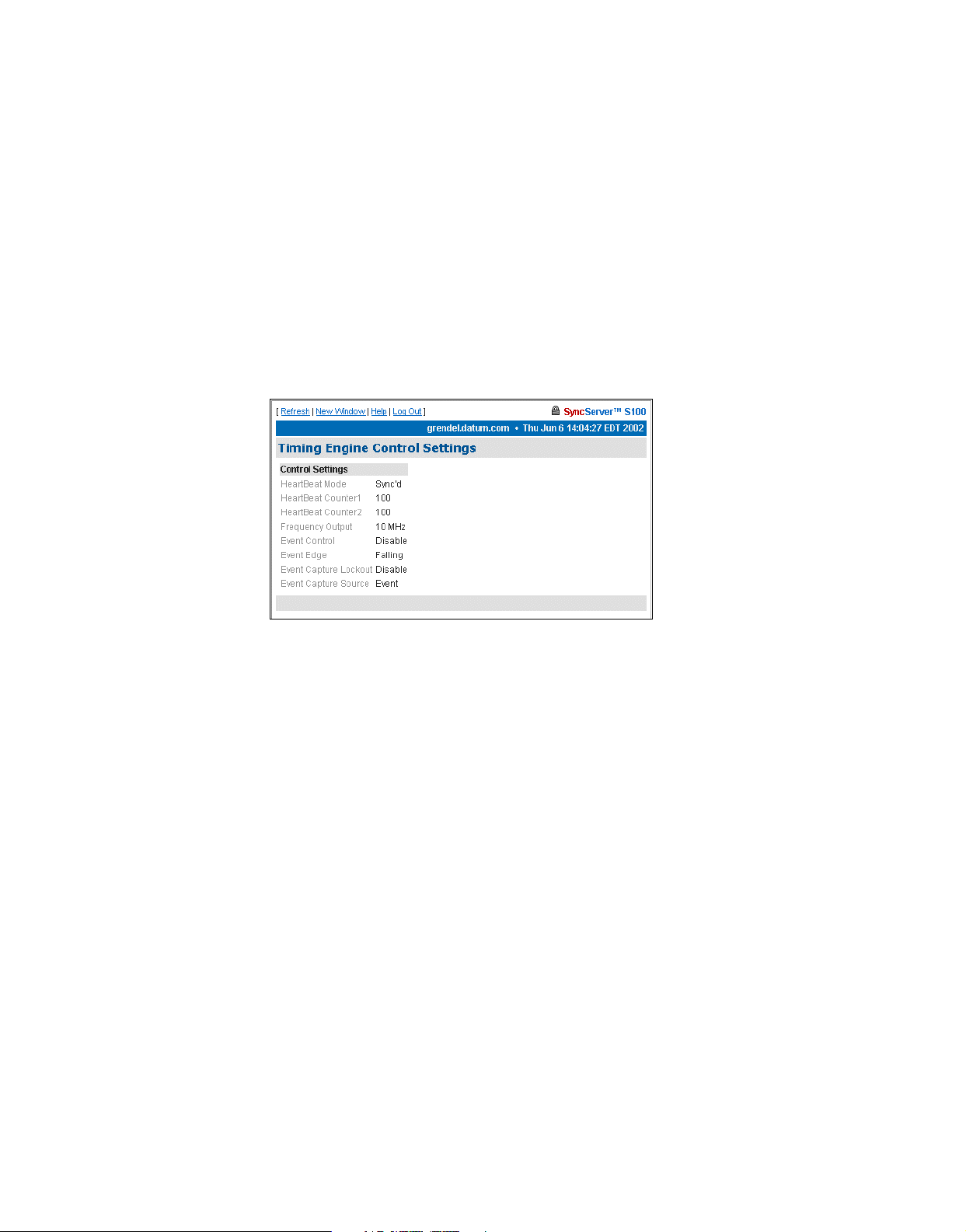
Disc Control - Short for disciplining control, this disciplining function is the part of the
software that matches the local clock phase and frequency with the selected time reference
function.
Phase Control - Short for local clock phase shifting, this function shows if the software is
shifting the one-second rollover point of the local hardware clock by a specified amount.
Disc Gain - Short for oscillator disciplining function gain value, this is a scalar value that
sets the gain for the Kalman filter so it can discipline the local oscillator to the selected time
reference.
Control Settings
The timing engine control settings are viewable here.
2
3
Figure 4-20: Control Settings
They are:
HeartBeat Mode - The heartbeat is the specified frequency.
HeartBeat Counter1 and 2 - These are internal counters to the timing engine.
5
Frequency Output - The available frequencies are 1, 5, and 10 MHz.
Event Control - This setting enables or disables the ability of the internal clock to capture the
time at which an external event occurs.
Event Edge - This is either the rising or falling edge of the heartbeat signal.
Event Capture Lockout - If enabled, the capture lockout can be used to control whether or
not subsequent signals will overwrite the data in the timing engine’s event time registers.
Event Capture Source - This setting controls the source of the external event—an external
event input or strobe, for example.
S100 User Guide – Rev. D – June 2005 71
Page 80

Model Information
The following page provides basic data about the bc635/637 PCI board, the timing engine of
the S100.
Networking
SyncServer S100
Figure 4-21: Timing Engine Model Information
TCP/IP
Use the following dialogs to configure several parameters of the S100 on your network.
The following dialog enables you to define the following parameters:
Figure 4-22: Configuring TCP/IP
Network Interface - Here, choose the Ethernet port you are using. If there is only one
interface, use eth0, the default. A local loopback refers to a loopback plug inserted in one
72 S100 User Guide – Rev. D – June 2005
Page 81

of the ports; a signal is transmitted and returned to the sending device and the returned
signal is compared with the transmitted signal in order to evaluate the integrity of the
equipment or transmission path.
DHCP - This is the Dynamic Host Configuration Protocol, which assigns an IP address to
each node in a network. Here, the default is Enable.
Static IP - Click the radio button to Enable, then enter the S100’s IP address, subnet mask,
and default gateway.
The setting for On Boot is defaulted to Enable. Uncheck this box if you do not want the IP
address when you reboot.
Local Domain - This is your local domain name.
Search Domains - The system will search these domains—which usually include your local
domain as well as others—so it can resolve any unresolved host names that may be missing
the host, local, or top level portion of the name.
Hostname - Enter the S100’s name here.
IP Forwarding - You can redirect data from one IP address to another by selecting Enable
here.
DNS Nameservers - These are the DNS servers on the network.
Reset - Click this button to return to the previous settings.
2
3
Update/Reboot - Click this button to reboot the server, but please note the warning:
Warn ing
If you click Update/Reboot, you will
reboot the server, and will need to
reacquire time. Be certain you want to do
this.
If you do choose to do this, a confirmation message will display at the top if this screen.
5
S100 User Guide – Rev. D – June 2005 73
Page 82

ifconfig Output
This screen gives you information about the network configuration of the S100. It lets you
troubleshoot network problems.
SyncServer S100
Figure 4-23: Configuration Information
Ping
Use the ping command to test the network route between the S100 and a remote host.
Figure 4-24: Pinging the Remote Host
This is a diagnostic tool that confirms that all is well between the two devices.
The dialog shown in Figure 4-24 lets you define the following parameters:
Host - URL of the remote host
74 S100 User Guide – Rev. D – June 2005
Page 83

Wait time - Response time between pings
Ping count - Try to ping this number of times before quitting
Options -
Traceroute
Traceroute shows you the network route between the S100 and a remote host. Use it as a
diagnostic tool.
• Route: Gives detailed information about the route followed between two hosts
• Quiet: No output until done
• Allow Ping of Broadcast Address: Lets you ping broadcast addresses so all
machines in a broadcast group can respond
2
3
5
Figure 4-25: Seeing the Traceroute
The dialog shown in Figure 4-25 lets you determine the following parameters:
Host - Remote server’s IP address
Source Network Interface - The S100 has two Ethernet cards, 0 (zero, left) and 1 (right).
The default is eth0, as you see here.
Response Wait Timeout - This is how long the S100 should wait for a host to respond.
Base UDP Port - This refers to the User Datagram Protocol port number. The default is port
33434.
Options -
S100 User Guide – Rev. D – June 2005 75
Page 84

• Skip Name Lookup: If you check this, the S100 will not take the time to look up the
host names of the intermediate hosts along the path.
Administration
Here, configure non-NTP features of the S100. You can also shut down or restart the S100.
Shutdown/Reboot
This option shuts down the network connection.
SyncServer S100
WARNING!
If you click Shutdown, you
will shut down the S100’s
network connection.
When - Using a 24-hour clock, enter the time here.
Figure 4-26: Shutdown/Reboot
Options - These are:
• Cancel Pending Shutdown: Lets you cancel a shutdown
• Reboot: The default setting. Useful if you need to shut down and restart the hardware
and software. This is very handy if the S100 is remote
• File System Check on Reboot: Here the system checks for errors, lost clusters, and
other problems
Message - Here, enter a message that would be sent only to someone who might be logged
in using Secure Shell.
76 S100 User Guide – Rev. D – June 2005
Page 85

Reset - Click Reset to clear the data you have entered.
Submit - Clicking Submit to disconnect the server from the network.
Admin Users
Use this dialog to change, delete, or add a user.
2
3
Figure 4-27: Changing or Adding Users
Restart Web Interface
This page lets you do a clean restart of the web server.
The restart affects only the management of the system, not the time or service.
WARNING
If you click Restart, you will
shut down the webserver,
then it will restart. This will
take a minute or two to
complete.
Figure 4-28: Server Restart option
5
S100 User Guide – Rev. D – June 2005 77
Page 86

Time Zone
Use this option to set the time zone displayed in the web-based admin interface.
The time zone is for display purposes only. It will not affect NTP, the output, or clients.
Highlight the time zone you want, then click Submit to set the time zone.
SyncServer S100
Figure 4-29: Setting the Time Zone
System Log Configuration
Use this option to configure the System Log.
Note: Remote logging is available by specifying an IP address preceded by an @ sign.
Figure 4-30: System Log Configuration
78 S100 User Guide – Rev. D – June 2005
Page 87

SNMP Configuration
2
Figure 4-31: SNMP Configuration
When populated with text, this screen is a summary of the SNMP configuration commands
entered in the SNMP Edit screen.
SNMP Edit
3
5
Figure 4-32: SNMP Edit
Use this screen to enter your SNMP commands for configuration and any other related
information.
S100 User Guide – Rev. D – June 2005 79
Page 88

Alarms
SyncServer S100
This page lets you configure alarm activity
.
Figure 4-33: Setting Alarm Parameters
E-mail Address - This e-mail address is where any alarm messages will be sent.
Mail forwarder - The server that will handle the e-mail.
Issue Alarms - Here, check when you want alarms sent:
• Upon boot, and if Flywheeling continues for more than 60 seconds. If you check here
for this alarm, it will tell you that the system has lost contact with its source of time but
will keep going for some period.
• If there has been a Configuration Change, you can check here for an alarm to be
sent.
Reset lets you clear the entered data, and Submit tells the system you are finished.
Configuration Wizard
The next item on the Admin menu is the Configuration Wizard. This helps you select and
configure your time reference.
Step-by-step Configuration Wizard instructions are in “The Configuration Wizard” on
page 32.
80 S100 User Guide – Rev. D – June 2005
Page 89

Logs
You can access the NTP, Boot, System, Config and HTTPD logs through either the
admin menu or in the drop-down list box in the Logs parameter. All the logs have the
following parameters and values:
Logs - This drop-down list box lets you access other logs from this screen. The size of the log
you choose will be displayed beneath the drop-down box.
Filter -
Prune -
NTP Log
Use this log to see NTP activity.
• No filter: Displays all logs.
• Display only the last __ lines: Useful for avoiding screen clutter.
• Search: Search feature allows you to see what has happened on any given day.
•Selecting the case-blind option lets the search ignore case in your search.
•Selecting the
•Choosing
line numbers option limits the search to log line numbers.
regular expression allows for pattern matching in your search.
2
3
• Remove all but the last __ lines: Lets you pare down the log after you have viewed
it.
5
Figure 4-34: NTP Log
S100 User Guide – Rev. D – June 2005 81
Page 90
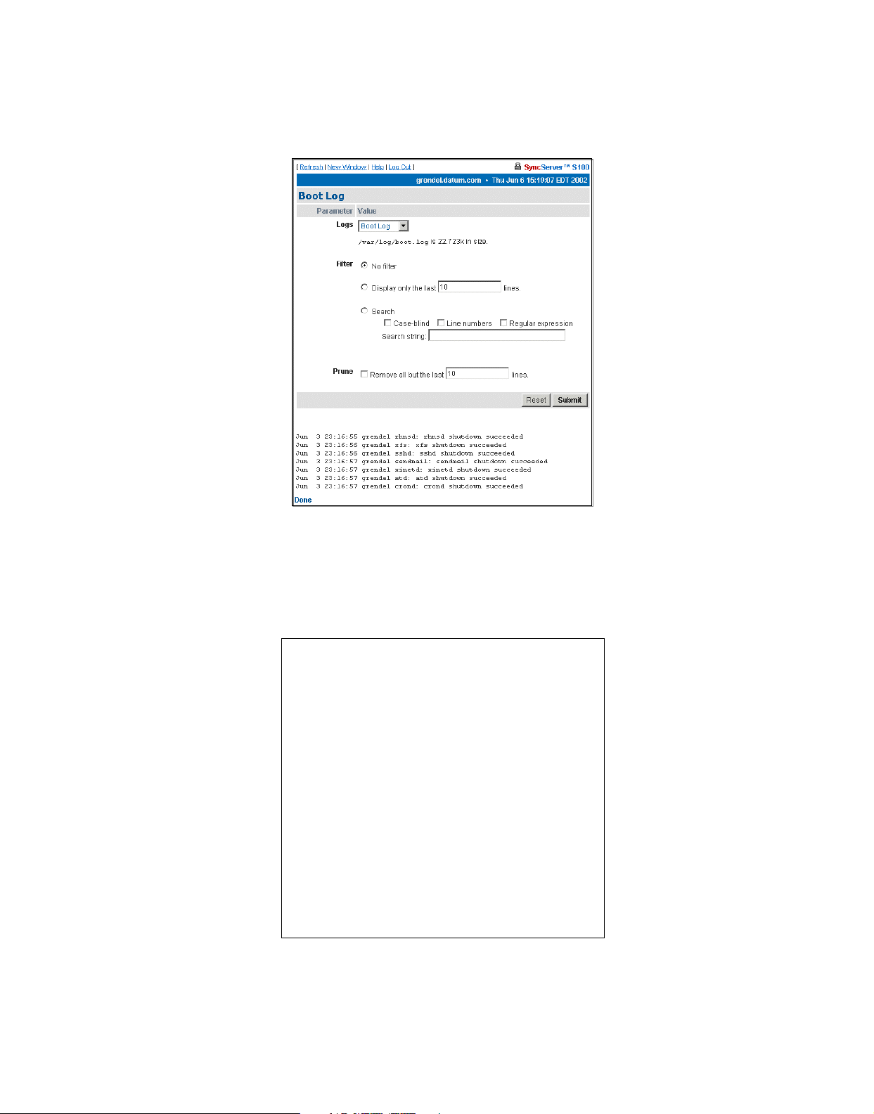
Boot Log
Use this log to see messages created during the boot process.
SyncServer S100
System Log
Use this log to monitor system activity.
Figure 4-35: Boot Log
Figure 4-36: System Log
82 S100 User Guide – Rev. D – June 2005
Page 91

Config Log
This log shows you S100 configuration and status messages.
HTTP Log
2
3
Figure 4-37: Config Log
This log shows webserver messages.
Figure 4-38: HTTP Log
5
S100 User Guide – Rev. D – June 2005 83
Page 92

Help
This is the last section of the S100 admin menu. Available Help functions are:
SyncServer Help
This is the application Help. Use the Table of Contents, Index, or Search to find information.
SyncServer S100
Figure 4-39: Help Options
NTPD Help
For detailed information about NTP (Network Time Protocol), use the NTPD Help link (see
“NTPD Help” on page 84
Distribution document (source: University of Delaware).
Additional information is available at
Search NTPD Manual
This option gives you the ability to do basic searches within the NTPD Help.
Collapse Button
Click the Collapse button at the bottom right of the admin menu to reduce the menu down to
its main elements.
) embedded in the S100’s web interface to review the NTP
http://www.ntp.org/.
84 S100 User Guide – Rev. D – June 2005
Page 93

Logging Off
Log off by clicking Log Out, at the top of each screen within the interface.
2
3
Figure 4-40: Log Off screen
You will see the System Status screen with some prompts. At this point, you can choose
among the following options:
• Log back in
• Go to the Configuration Wizard, which will require you to log b ack in but will then take you
directly to the wizard
• Continue the logoff by closing your browser
5
S100 User Guide – Rev. D – June 2005 85
Page 94

SyncServer S100
86 S100 User Guide – Rev. D – June 2005
Page 95

Chapter 5
Operations & Time-Protocols
S100: Operations and Time Protocols
Sysplex Timer
“Sysplex” means SYStem comPLEX, a term o ften used to d escribe continuous computing on
clusters of computers. The Sysplex Timer is sometimes called an External Time Reference
(ETR). The Sysplex Timer provides a synchronized Time-of-Day (TOD) clock for multiple
attached computers. A Sysplex is needed when two or more systems are configured in a
Sysplex. One Sysplex Timer can do the job, but it’s a good idea for you to have a second
duplex timer on the cluster as a backup in case the primary timer fails.
How the S100 Uses the Sysplex Timer
The S100 receives the signal from the GPS antenna, then provides Sysplex Timer output
through its Serial Port A. The Serial Port A supplies an ASCII broadcast of UTC time that is
often used by computers that cannot or do not use NTP.
Note: The GPS antenna described in this manual has been replaced as described in
“Appendix E” on page 141
Be sure your computer is set up with the correct Serial Port parameters—the correct baud
rate, data bits, stop bits, and p arity. The Serial Port will start broadcasting the time only after it
receives a c or C character. It will stop broadcast when it receives an r or R character. If you
set the Sysplex Timer to Auto on, the Sysplex Timer starts automatically on power up.
.
2
3
5
The following time information string is transmitted once per second, when started with the c
or C character. The DDD field represents three ASCII digits of days (001–366). The Quality
Indicator indicates the validity of the time. The Carriage Return character is transmitted ontime. The first rising edge of the Carriage Return character occurs within 100 microseconds
after the S100 1PPS signal transitions from low to high.
S100 User Guide – Rev. D – June 2005 87
Page 96

SyncServer S100
Figure 5-41:
Time Information String Parameters
Comm parameters can be controlled by modifying the /etc/.ss_profile file.
Various operational parameters for the sysplex daemon can be controlled using parameters
in the .ss_profile file. Use the serial connection or SSH to login to the S100 in order to
change this file. Set the value of the SYSPLEX_PROGRAM environment variable by adding
or removing the # comment character in the first column. For example:
# which sysplex program shall we run
SYSPLEX_PROGRAM=sysplex
#SYSPLEX_PROGRAM=sysplexoddp
#SYSPLEX_PROGRAM=sysplexnof
#SYSPLEX_PROGRAM=sysplexoddpnof
SYSPLEX_OPTIONS=on
will run the standard (9600,8,n,1) version of the protocol while:
# which sysplex program shall we run
#SYSPLEX_PROGRAM=sysplex
SYSPLEX_PROGRAM=sysplexoddp
#SYSPLEX_PROGRAM=sysplexnof
#SYSPLEX_PROGRAM=sysplexoddpnof
SYSPLEX_OPTIONS=on
88 S100 User Guide – Rev. D – June 2005
Page 97

will run the odd parity (9600,8,o,1) version of the protocol. The currently availab le versions of
the protocol are:
• sysplex (9600,8,n,1)
• sysplexoddp (9600,8,o,1)
• sysplexnof (9600,8,n,1) with the 'F' (see sysplex definition) suppressed.
• sysplexoddpnof (9600,8,o,1) with the 'F' (see sysplex definition) suppressed.
The SYSPLEX_OPTIONS environment variable can be set to either "on" or blank. A value of
"on" will result in the sysplex protocol broadcast being automatically started instead of waitin g
for a start character. An empty or blank value will not.
Note: NOTE: The sysplex daemon must be restarted in order for the changes to take effect. The
easiest way to do this is to reboot the box using either the web interface or the reboot command. If there are any problems, a copy of the factory profile is kept in the /etc directory with
the name .ss_profile.original . The factory settings may be restored by copying the backup file
over the modified version using:
cp /etc/.ss_profile.original /etc/.ss_profile
Time Protocol (RFC 868)
This protocol provides a site-independent, machine-readable date and time. The time service
on the S100 responds to the originating source with the time in seconds since midnight of
January 1, 1900. The time is the number of seconds since 00:00 (midnight) January 1, 1900
GMT. So the time “1” is 12:00:01 A.M. on January 1, 1900 GMT . This base will serve until the
year 2036.
If the server is unable to determine the time, it either refuses the connection or it closes the
connection without sending any response.
When used over the Transmission Control Protocol (TCP), the S100 listens for a connection
on port 37; once the connection is established, the server returns a 32-bit time value and
closes the connection. When used over the User Datagram Protocol (UDP), the S100 listens
for a datagram on port 37. When a dat agram arrives, the S100 ret urns a data gram containing
the 32-bit time value.
2
3
5
For additional information, see
http://www.faqs.org/rfcs/rfc868.html
Daytime Protocol (RFC 867)
The Daytime protocol sends the current date and time as a character string without regard to
the input.
When used over TCP, the S100 listens for a connection on port 13; once a connection is
established the current date and time is sent out as an ASCII character string. The service
closes the connection after sending the quote.
S100 User Guide – Rev. D – June 2005 89
Page 98

SyncServer S100
When used over UDP, the S100 listens for a datagram on port 13. The S100 responds to the
UDP request with the current date and time as an ASCII character string.
For additional information, see:
http://www.faqs.org/rfcs/rfc867.html.
Simple Network Time Protocol (RFC 2030)
Simple Network Time Protocol (SNTP) is a simplified access protocol for servers and clients
using NTP as it is now used on the Internet. The access paradigm is identical to the UDP/
Time client implementation. SNTP is also designed to operate on a dedicated server
configuration, including an integrated radio clock. SNTP uses the standard NTP time stamp
format described in RFC 1305 and previous versions of that document. NTP stamps are
represented as a 64-bit unsigned, fixed-point number, in seconds relative to 0
1900.
For additional information, see:
http://www.faqs.org/rfcs/rfc2030.html.
Network Time Protocol (RFC 1305)
The Network Time Protocol (NTP) is used to synchronize computer clocks in a TCP/IP
computer network. It provides a comprehensive mechanism for accessing national time and
frequency distribution services, for organizing the time-synchronization subnet, and for
adjusting the local clocks. NTP provides accuracy of 1-10 milliseconds (ms), depending on
the jitter characteristics of the synchronization source and network paths. NTP uses User
Datagram Protocol (UDP), which is a sub-protocol of the Internet Protocol (IP).
h
on January 1,
Some definitions follow. For more, see “Time Glossary” on page 121
For additional information, see
http://www.faqs.org/rfcs/rfc1305.html.
.
NTP Data Format
The format of the NTP message data area, which immediately follows the UDP header, is
shown in Figure 3-2. NTP time stamps are represented as a 64 bit unsigned fixed-point
h
number , in secon ds relative to 0
on 1 January 1900. The integer portion is in the first 32 bits
and the fractional portion is in the last 32 bits.
90 S100 User Guide – Rev. D – June 2005
Page 99

Table Intro-1: NTP Message Data
0 8 16 24 31
LI VN MODE Stratum Poll Precision
Synchronizing Distance (Root Distance) (32 bits)
Synchronizing Dispersion (Root Dispersion) (32 bits)
Reference Identifier (32 bits)
Reference Time Stamp (64 bits)
Originate Time Stamp (64 bits)
Receive Time Stamp (64 bits)
Transmit Time Stamp (64 bits)
Authenticator (Optional) (96 bits)
2
3
Leap Indicator (LI)
This is a two-bit code warning of an impending leap second that will be inserted or deleted in
the last minute of the current day, with bit 0 and bit 1, respectively, coded as follows:
5
Figure 5-42: Two-bit Leap Second Indicator Code
You are alerted to an alarm condition when the S100 is first powered on—in other words,
before time is initially acquired from the timing signal. An alarm condition will also signal when
the timing parameters are changed. This alarm condition will persist until the S100 acquires
time. It should not signal again until the unit is powered off and on.
Version Number (VN)
This is a three-bit integer indicating the NTP version number. The S100 will return the version
number from the incoming NTP message.
S100 User Guide – Rev. D – June 2005 91
Page 100

SyncServer S100
Mode
This is a three-bit integer indicating the mode. The S100 can be operated in any mode.
Stratum
This is an eight-bit integer indicating the stratum level of the local clock. For the S100 this
field is set to one indicating a primary reference, if the S100 is relying on its GPS receiver or
dial-up modem connection for timing information. Otherwise, it will accurately reflect its
location in a timing hierarchy.
Poll Interval
This is an eight-bit signed integer indicating the maximum interval between successive
messages, in seconds to the nearest power of two. The S100 will return the poll interval from
the incoming NTP message.
Precision
This is an eight-bit signed integer indicating the precision of the local clock, in seconds to the
nearest power of two. For the S100 this field is set to –19 (minus nineteen), which is the value
closest to the 1u sec precision of the S100 when operating in GPS mode.
Synchronizing Distance (Root Distance Version 3)
This is a 32-bit fixed-point number indicating the estimated round-trip delay to the primary
synchronizing source, in seconds with fraction point between bits 15 and 16. Set to zero in
the S100 for GPS mode and a corresponding value when operating with another time source .
Synchronizing Dispersion (Root Dispersion Version 3)
Synchronizing Dispersion is a 32 bit fixed-point number indicating the estimated dispersion to
the primary synchronizing source, in seconds. Root Dispersion indicates the maximum error
relative to the primary reference source.
Reference Clock Identifier
This is a 32-bit code identifying the particular reference clock. In the case of Stratum 1
(primary reference), this is a four-octet, left justified, zero-padded ASCII string. For the S100
the four-octet string is dependent on the time source selected, ‘GPS’ fo r GPS and ‘FREE’ for
Free Running Clock. If the unit is synchronizing to anoth er S100, the reference clock identifier
will contain the four-byte address of the selected S100.
Reference Timestamp
This is the local time at which the local clock was last set or corrected, in 64-bit timestamp
format. With the S100, the Reference Timest amp is the last time that a valid timing signal was
92 S100 User Guide – Rev. D – June 2005
 Loading...