


MC3090BT

Accessories
Chapter Contents
Introduction . . . . . . . . . . . . . . . . . . . . . . . . . . . . . . . . . . . . . . . . . . . . . . . . . . . . . . . . . . . . . . . . . . . . . . . . . . . . .4-3
Cradles . . . . . . . . . . . . . . . . . . . . . . . . . . . . . . . . . . . . . . . . . . . . . . . . . . . . . . . . . . . . . . . . . . . . . . . . . . . . .4-3
Spare Battery Chargers . . . . . . . . . . . . . . . . . . . . . . . . . . . . . . . . . . . . . . . . . . . . . . . . . . . . . . . . . . . . . . . .4-3
Cables. . . . . . . . . . . . . . . . . . . . . . . . . . . . . . . . . . . . . . . . . . . . . . . . . . . . . . . . . . . . . . . . . . . . . . . . . . . . . . 4-3
SD Card. . . . . . . . . . . . . . . . . . . . . . . . . . . . . . . . . . . . . . . . . . . . . . . . . . . . . . . . . . . . . . . . . . . . . . . . . . . . .4-3
Plastic Holster . . . . . . . . . . . . . . . . . . . . . . . . . . . . . . . . . . . . . . . . . . . . . . . . . . . . . . . . . . . . . . . . . . . . . . .4-3
Fabric Holster . . . . . . . . . . . . . . . . . . . . . . . . . . . . . . . . . . . . . . . . . . . . . . . . . . . . . . . . . . . . . . . . . . . . . . . .4-3
Single Slot Serial/USB Cradle . . . . . . . . . . . . . . . . . . . . . . . . . . . . . . . . . . . . . . . . . . . . . . . . . . . . . . . . . . . . . . .4-4
Battery Charging. . . . . . . . . . . . . . . . . . . . . . . . . . . . . . . . . . . . . . . . . . . . . . . . . . . . . . . . . . . . . . . . . . . . . .4-4
Four Slot Cradles . . . . . . . . . . . . . . . . . . . . . . . . . . . . . . . . . . . . . . . . . . . . . . . . . . . . . . . . . . . . . . . . . . . . . . . . .4-6
Battery Charging. . . . . . . . . . . . . . . . . . . . . . . . . . . . . . . . . . . . . . . . . . . . . . . . . . . . . . . . . . . . . . . . . . . . . .4-6
LED Charge Indications . . . . . . . . . . . . . . . . . . . . . . . . . . . . . . . . . . . . . . . . . . . . . . . . . . . . . . . . . . . . . . . .4-7
Power LED . . . . . . . . . . . . . . . . . . . . . . . . . . . . . . . . . . . . . . . . . . . . . . . . . . . . . . . . . . . . . . . . . . . . . . . . . .4-7
Speed LED . . . . . . . . . . . . . . . . . . . . . . . . . . . . . . . . . . . . . . . . . . . . . . . . . . . . . . . . . . . . . . . . . . . . . . . . . .4-7
Link LED . . . . . . . . . . . . . . . . . . . . . . . . . . . . . . . . . . . . . . . . . . . . . . . . . . . . . . . . . . . . . . . . . . . . . . . . . . . .4-7
Four Slot Spare Battery Charger . . . . . . . . . . . . . . . . . . . . . . . . . . . . . . . . . . . . . . . . . . . . . . . . . . . . . . . . . . . . .4-8
Spare Battery Charging . . . . . . . . . . . . . . . . . . . . . . . . . . . . . . . . . . . . . . . . . . . . . . . . . . . . . . . . . . . . . . . .4-8
LED Charge Indications . . . . . . . . . . . . . . . . . . . . . . . . . . . . . . . . . . . . . . . . . . . . . . . . . . . . . . . . . . . . . . . .4-8
Cables. . . . . . . . . . . . . . . . . . . . . . . . . . . . . . . . . . . . . . . . . . . . . . . . . . . . . . . . . . . . . . . . . . . . . . . . . . . . . . . . . .4-9
Battery Charging and Operating Power . . . . . . . . . . . . . . . . . . . . . . . . . . . . . . . . . . . . . . . . . . . . . . . . . . .4-10
LED Charge Indications . . . . . . . . . . . . . . . . . . . . . . . . . . . . . . . . . . . . . . . . . . . . . . . . . . . . . . . . . . . . . . .4-10
Universal Battery Charger (UBC) Adapter . . . . . . . . . . . . . . . . . . . . . . . . . . . . . . . . . . . . . . . . . . . . . . . . . . . . .4-11
Spare Battery Charging . . . . . . . . . . . . . . . . . . . . . . . . . . . . . . . . . . . . . . . . . . . . . . . . . . . . . . . . . . . . . . .4-11
UBC Adapter LED Charge Indications . . . . . . . . . . . . . . . . . . . . . . . . . . . . . . . . . . . . . . . . . . . . . . . . . . . .4-12
Secure Device Card . . . . . . . . . . . . . . . . . . . . . . . . . . . . . . . . . . . . . . . . . . . . . . . . . . . . . . . . . . . . . . . . . . . . . .4-13

MC3000 User Guide4-2
Plastic Holster. . . . . . . . . . . . . . . . . . . . . . . . . . . . . . . . . . . . . . . . . . . . . . . . . . . . . . . . . . . . . . . . . . . . . . . . . . .4-14
Fabric Holster . . . . . . . . . . . . . . . . . . . . . . . . . . . . . . . . . . . . . . . . . . . . . . . . . . . . . . . . . . . . . . . . . . . . . . . . . . .4-16
Belt Clip . . . . . . . . . . . . . . . . . . . . . . . . . . . . . . . . . . . . . . . . . . . . . . . . . . . . . . . . . . . . . . . . . . . . . . .4-16
Shoulder Strap . . . . . . . . . . . . . . . . . . . . . . . . . . . . . . . . . . . . . . . . . . . . . . . . . . . . . . . . . . . . . . . . . .4-17

Accessories 4-3
Introduction
The MC3000 accessories provide a variety of product support capabilities. Accessories include cradles, cables, spare battery chargers
and SD cards.
Cradles
• The Single Slot Serial/USB cradle charges the mobile computer main battery and/or a spare battery. It also synchronizes the
mobile computer with a host computer through either a serial or a USB connection.
• The Four Slot Charge Only cradle charges up to four mobile computers.
• The Four Slot Ethernet cradle charges up to four mobile computers and provides Ethernet communication.
Spare Battery Chargers
• Four Slot Spare Battery Charger charges up to four MC3000 spare batteries.
• UBC Adapter adapts the UBC2000 for use with the MC3000 batteries.
The accessory power supply regulatory compliance statements are provided in Table C-1 on page C-3.
Cables
The cables snap on to the mobile computer and are used to connect external devices to the mobile computer.
• USB client charge cable
• RS232 Charge cable
• O’Neil printer cable
• Zebra printer cable
• Monarch printer cable.
SD Card
The SD card provides additional storage capacity for the mobile computer.
Plastic Holster
The Plastic Holster provides a clip on holder for the mobile computer.
Fabric Holster
The Fabric Holster provides a clip on holder for the mobile computer.
MC3000 User Guide4-4
Single Slot Serial/USB Cradle
The Single Slot Serial/USB cradle:
• Provides 5.4VDC power for operating the mobile computer, charging the battery and charging a spare battery.
• Provides a serial port and a USB port for data communication between the mobile computer and a host computer or other
serial devices (e.g., a printer).
• Synchronizes information between the mobile computer and a host computer. With customized or third party software, it can
also synchronize the mobile computer with corporate databases.
• Provides serial connection through the serial pass-through port for communication with a serial device, such as a host
computer. For communication setup procedures, refer to the MC3000 Integrator Guide.
• Provides USB connection through the USB pass-through port for communication with a USB device, such as a host computer.
For communication setup procedures, refer to the MC3000 Integrator Guide.
Use only a Symbol approved power supply output rated 12 VDC and minimum 3.3 A. Use of an alternative
power supply will void the product warranty and may cause product damage. See Appendix C, Regulatory for
the power supply regulatory compliance statement.
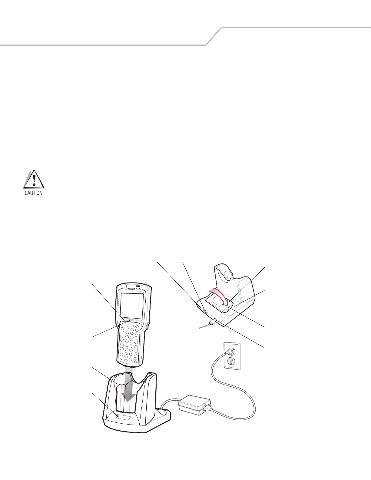
Battery Charging
The Single Slot Serial/USB cradle can charge the mobile computer main battery and a spare battery simultaneously.
To charge the mobile computer:
1. Slide the mobile computer into the mobile computer slot. The mobile computer amber Charge LED Indicator, indicates the
mobile computer battery charging status. The Standard Battery charges in less than four hours and the Extended Life Battery
charges in less than six hours. See Table 4-1 for charging status indications.
Figure 4-1. Single Slot Serial/USB Cradle
2. When charging is complete, remove the mobile computer from the mobile computer slot.
Indicator
LED Bar
Mobile
Computer Slot
Spare
Battery
Spare
Battery
Charging
LED
Power Port
Serial Port
USB Port
Spare
Battery
Charging
Slot
Battery
Clip
Charge LED
Indicator
(amber)
Accessories 4-5
To charge the spare battery:
1. Insert the spare battery into the spare battery charging slot, bottom first, and pivot the top of the battery down onto the
contact pins.
2. Gently press down on the battery to ensure proper contact.
3. The Spare Battery Charging LED (see Figure 4-1 on page 4-4) indicates the spare battery charging status. The
Standard Battery charges in less than four hours and the Extended Life Battery charges in less than six hours. See
Table 4-1 for charging status indications.
4. When charging is complete, press the battery clip and lift the battery out of the slot.
LED Charge Indications
The Single Slot Serial/USB cradle uses the mobile computer amber Charge LED Indicator to indicate the battery charging status and
the Spare Battery Charging LED to indicate spare battery charging status. See Table 4-1 for charging status indications.
Table 4-1. LED Charging Status Indicators
LED Indication
Mobile Computer Charging (LED on mobile computer)
Off Mobile computer not placed correctly in the cradle; cable not connected correctly; charger is not powered.
Fast Blinking Amber Error in charging; check placement of mobile computer.
Slow Blinking Amber Mobile computer is charging.
Solid Amber Charging complete.
Note: When the battery is initially inserted in the mobile computer, the amber LED flashes once if the battery
power is low or the battery is not fully inserted.
Spare Battery Charging (LED on cradle)
Off No spare battery in slot; spare battery not placed correctly; cradle is not powered.
Fast Blinking Amber Error in charging; check placement of spare battery.
Slow Blinking Amber Spare battery is charging.
Solid Amber Charging complete.
MC3000 User Guide4-6
Four Slot Cradles
There are two four slot cradles, Four Slot Charge Only cradle and Four Slot Ethernet cradle. The Four Slot Ethernet cradle provides
Ethernet communications. Both four slot cradles:
• Provide 5.4 VDC power for operating the mobile computer and charging the battery.
• Simultaneously charges up to four mobile computers.
Use only a Symbol approved power supply output rated 12 VDC and minimum 9 A. Use of an alternative power
supply will void the product warranty and may cause product damage. See Appendix C, Regulatory for the
power supply regulatory compliance statement.
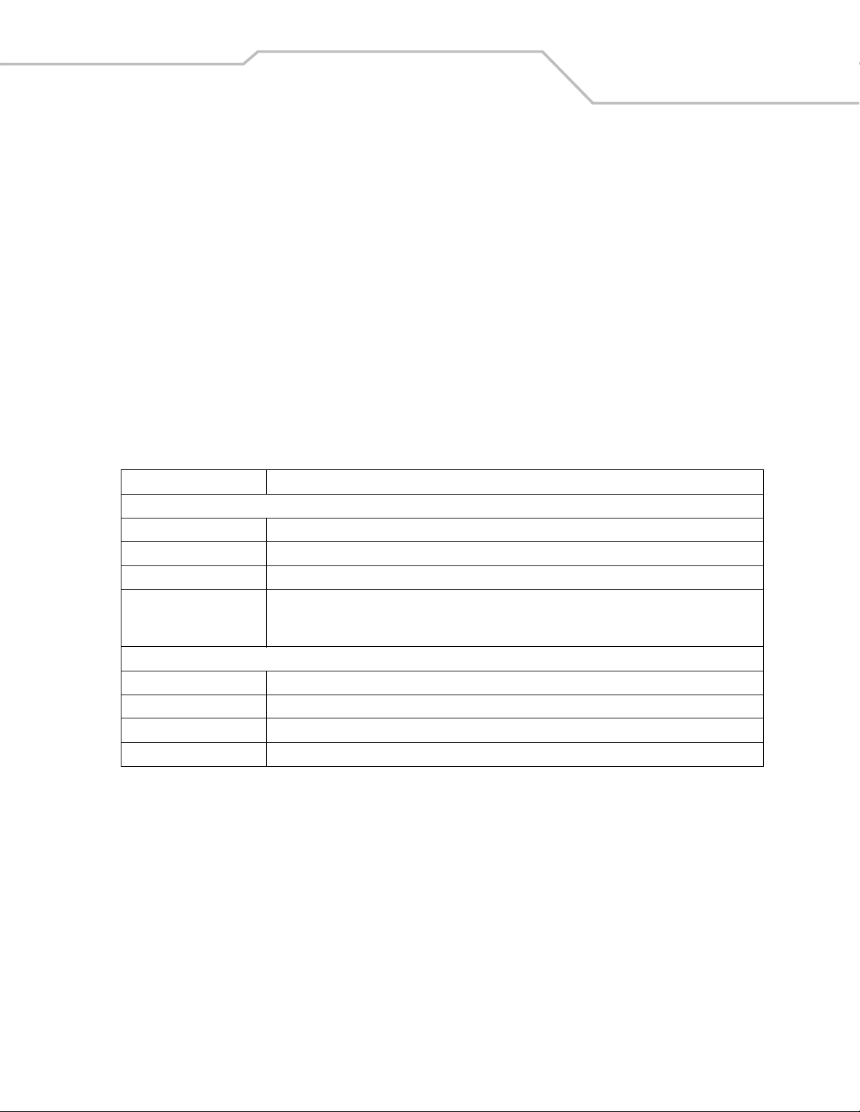
Battery Charging
The four slot cradle can charge up to four mobile computers simultaneously. To charge the mobile computer:
1. Slide the mobile computer into the mobile computer slot.
Figure 4-2. Four Slot Cradles
2. The mobile computer amber Charge LED Indicator, indicates the mobile computer battery charging status. The Standard
Battery usually charges in less than four hours and the Extended Life Battery usually charges in less than six hours. See Table
4-1 for charging status indications.
3. When charging is complete, remove the mobile computer from the cradle.
Scan/Charge Indicator LED Bar
Mobile Computer Slot
Charge LED Indicator (amber)
Speed LED (Ethernet Cradle Only)
Link LED (Ethernet Cradle Only)
Power LED (Charge Only Cradle)

Accessories 4-7
LED Charge Indications
The Four Slot cradles use the mobile computer amber Charge LED Indicator to indicate the battery charging status. See Table
4-1 on page 4-5 for charging status indications.
Power LED
The green Power LED (only on the Four Slot Charge Only cradle) lights to indicate that the Four Slot Charge Only cradle is connected
to a power source.
Speed LED
The green Speed LED (only on the Four Slot Ethernet cradle) lights to indicate that the transfer rate is 100 Mbps. When it is not lit it
indicates that the transfer rate is 10 Mbps.
Link LED
The yellow Link LED (only on the Four Slot Ethernet cradle) blinks to indicate activity, or stays lit to indicate that a link is established.
When it is not lit, it indicates that there is no link.
MC3000 User Guide4-8
Four Slot Spare Battery Charger
The Four Slot Spare Battery Charger simultaneously charges up to four spare batteries.
Use only a Symbol approved power supply output rated 12 VDC and minimum 3.3 A. Use of an alternative
power supply will void the product warranty and may cause product damage. See Appendix C, Regulatory for
the power supply regulatory compliance statement.
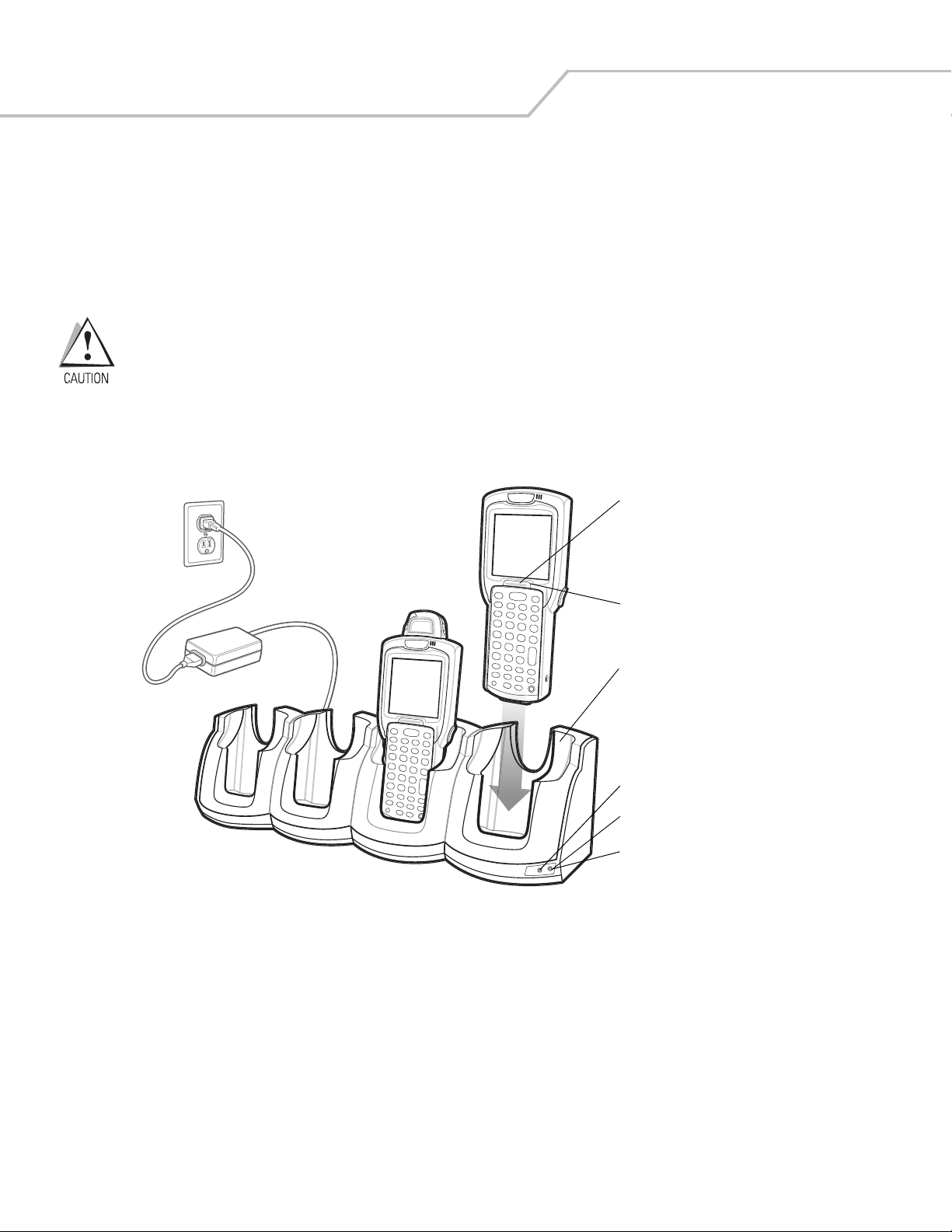
Spare Battery Charging
To charge up to four MC3000 spare batteries:
1. Insert the spare battery into the spare battery charging slot, bottom first.
2. Pivot the top of the battery down onto the contact pins.
Figure 4-3. Four Slot Spare Battery Charger
3. Gently press down on the battery to ensure proper contact. The Standard Battery usually charges in less than four hours and
the Extended Life Battery usually charges in less than six hours. See Table 4-1 on page 4-5 for charging status indications.
4. When charging is complete, press the battery clip and lift battery out of the slot.
LED Charge Indications
The Spare Battery Charging LEDs indicate the spare battery charging status. The Spare Battery Charging LEDs are arranged in the
same pattern as the spare battery charging slots so that the charging status of each battery can be identified. See Table 4-1 on page
4-5 for charging status indications.
Power Supply
Spare
Batteries
Spare
Battery
Charging
Slot
Spare Battery
Charging LEDs (4)
Battery
Clip
1
2
Accessories 4-9
Cables
The cables are available with a variety of connection capabilities.
Use only a Symbol approved power supply output rated 5.4 VDC and minimum 3 A. Use of an alternative power
supply will void the product warranty and may cause product damage. See Appendix C, Regulatory for the
power supply regulatory compliance statement.
MC3000 Communication/Charge cables:
• Provide the mobile computer with operating and charging power when used with the Symbol approved power supply.
• Synchronize information between the mobile computer and a host computer. With customized or third party software, it can
also synchronize the mobile computer with corporate databases.
• Provide serial connection through the serial pass-through port for communication with a serial device, such as a host
computer. For communication setup procedures, refer to the MC3000 Integrator Guide.
• Provide USB connection through the USB pass-through port for communication with a USB device, such as a host computer.
For communication setup procedures, refer to the MC3000 Integrator Guide.
The following MC3000 Communication/Charge cables are available:
• Serial (RS232) Charge cable (9-pin D female with power input receptacle)
• USB Client Charge cable (standard-A connector and a barrel receptacle for power).
Dedicated Printer cables, provide communication with a dedicated printer.
The following printer cables are available directly from the printer manufacturer:
• O’Neil printer cable
• Zebra printer cable
• Monarch printer cable.
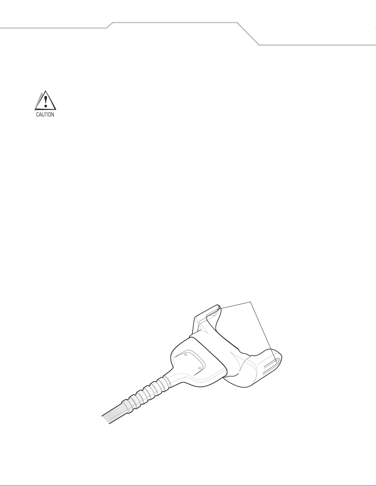
Figure 4-4. Cables
Snaps

MC3000 User Guide4-10
Battery Charging and Operating Power
The MC3000 Communication/Charge cables can charge the mobile computer battery and supply operating power.
To charge the mobile computer battery:
1. Connect the MC3000 Communication/Charge cable power input connector to the Symbol approved power source.
2. Slide the bottom of the mobile computer into the MC3000 connector end of the MC3000 Communication/Charge cable and
gently press in until the snaps latch into the mobile computer.
3. The mobile computer amber Charge LED Indicator indicates the mobile computer battery charging status. The Standard
Battery usually charges in less than four hours and the Extended Life Battery usually charges in less than six hours. See,
Table 4-1 on page 4-5 for charging status indications.
4. When charging is complete, remove the cable by gently pulling the mobile computer and the cable apart until the snaps
release the mobile computer.
LED Charge Indications
The MC3000 Communication/Charge cables use the amber Charge LED Indicator to indicate the MC3000 battery charging status. See,
Table 4-1 on page 4-5 for charging status indications.
Accessories 4-11
Universal Battery Charger (UBC) Adapter
The UBC Adapter can be used with a power supply as a standalone spare battery charger or it can be used with the four station
UBC2000 to simultaneously charge up to four spare batteries. For additional information on the UBC 2000, refer to the UBC 2000 Quick
Reference Guide p/n 70-33188-xx.
Use only a Symbol approved power supply output rated 15 VDC and minimum 1.5 A. Use of an alternative
power supply will void the product warranty and may cause product damage. See Appendix C, Regulatory for
the power supply regulatory compliance statement.
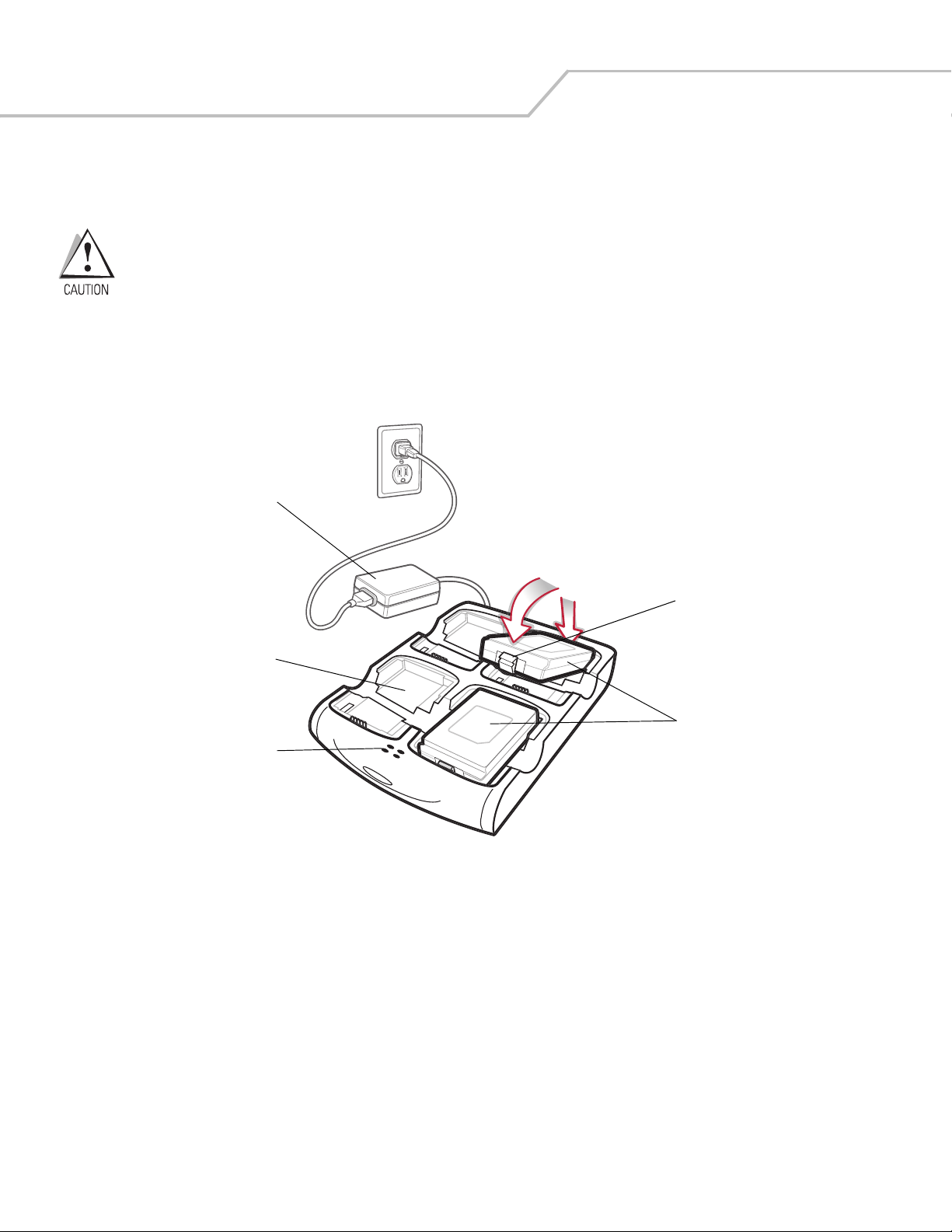
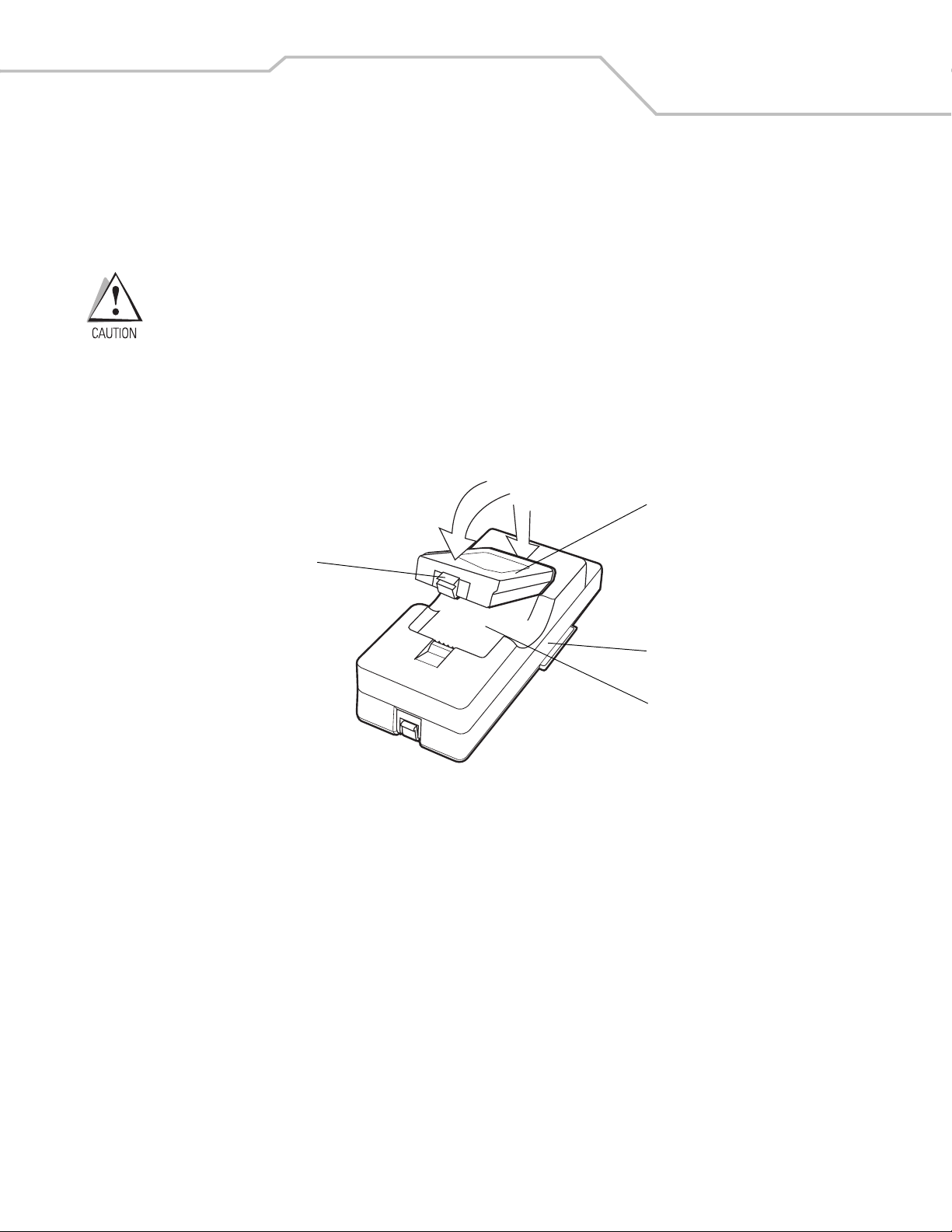
Spare Battery Charging
To charge spare batteries:
1. Insert the spare battery into the spare battery charging slot, bottom first.
2. Pivot the top of the battery down onto the contact pins.
Figure 4-5. UBC Adapter Battery Insertion
3. Gently press down on the battery to ensure proper contact. The Standard Battery usually charges in less than four hours and
the Extended Life Battery usually charges in less than six hours. See, Table 4-2 on page 4-12 for charging status indications.
4. When charging is complete, press the battery clip and lift the battery out of the slot.
UBC Adapter
Battery
Battery Clip
Spare Battery
Charging Slot
2
1
MC3000 User Guide4-12
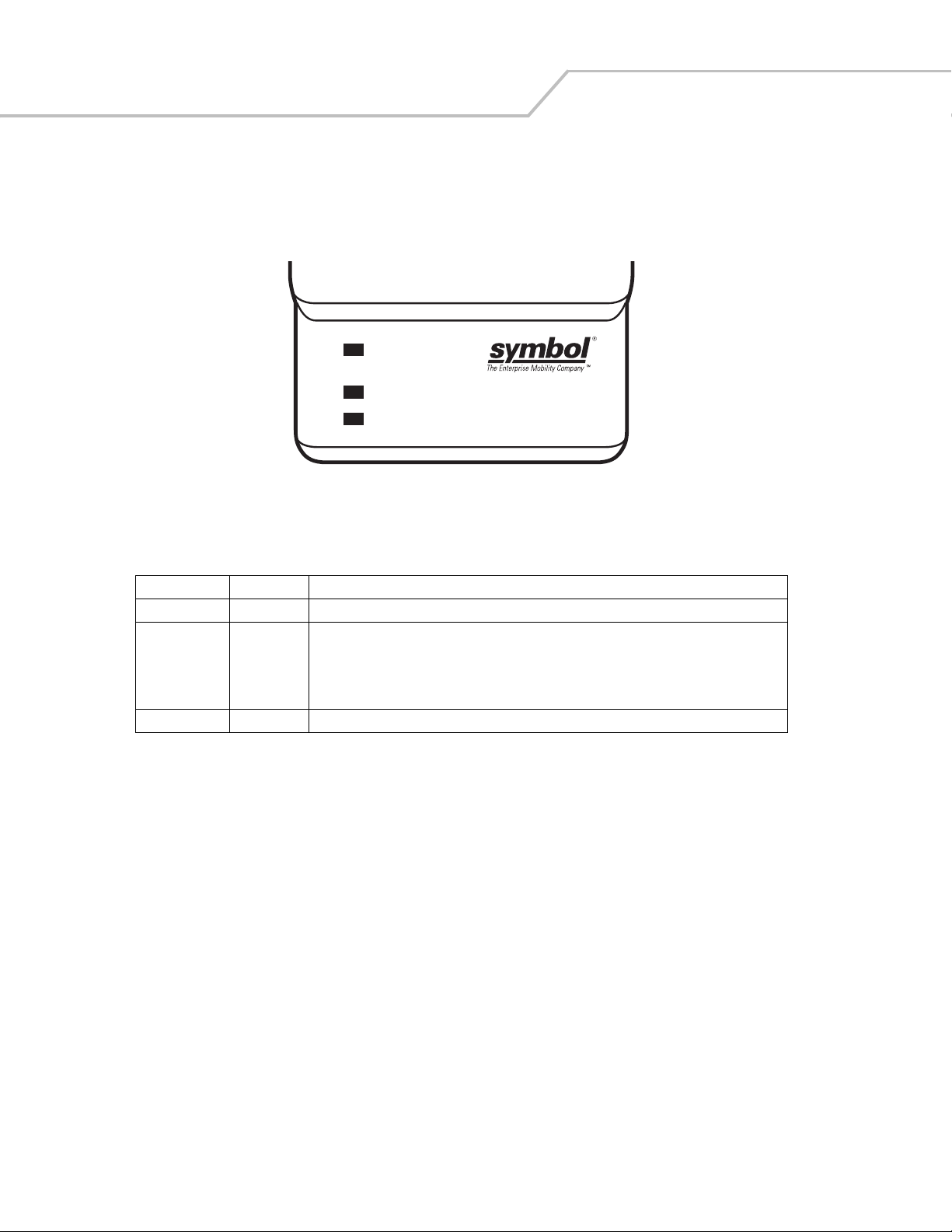
UBC Adapter LED Charge Indications
The UBC Adapter charging LEDs indicate the battery charging status. The Standard Battery usually charges in less than four hours
and the Extended Life Battery usually charges in less than six hours.
Figure 4-6. UBC Adapter LEDs
Table 4-2. UBC Adapter Charge LED Status Indications
LED Indication Description
POWER Green Power is connected to the UBC Adapter.
READY or Green Charging complete.
STANDBY or Flashing-
Yel low
The battery was deeply discharged and is being trickle charged to bring the voltage up to the
operating level. After operating level voltage is achieved, the battery charges normally.
FAULT Yellow Charging error, check placement of mobile computer/spare battery.
CHARGING Yellow Normal charge.
POWER
READY or STANDBY or FAULT
CHARGING
(Green) (Flashing Yellow) (Solid Yellow)
(Solid Yellow)

Accessories 4-13
Secure Device Card
The Secure Device (SD) card provides secondary non-volatile storage (the flash memory is slower than RAM). The SD card holder is
located under the battery.
Follow proper Electro-Static Discharge (ESD) precautions to avoid damaging the SD card. Proper ESD
precautions include, but are not limited to, working on an ESD mat and ensuring that the operator is properly
grounded.
Do not use the SD card slot for any other accessories.
Select SD cards with environmental and/or the write cycle performance specifications that meet or exceed
the application requirements.
To insert the SD card:
1. Remove the battery (see Main Battery Removal on page 1-12).
2. Lift the SD card retaining door.
3. Position the SD card, with the contacts down, into the SD card slot. The SD card corner notch fits into the slot only one way.
4. Close SD card retaining door.
Figure 4-7. Inserting the SD Card
5. Replace the battery (see Install Main Battery on page 1-6).
SD Card Retaining Door
SD Card
MC3000 User Guide4-14
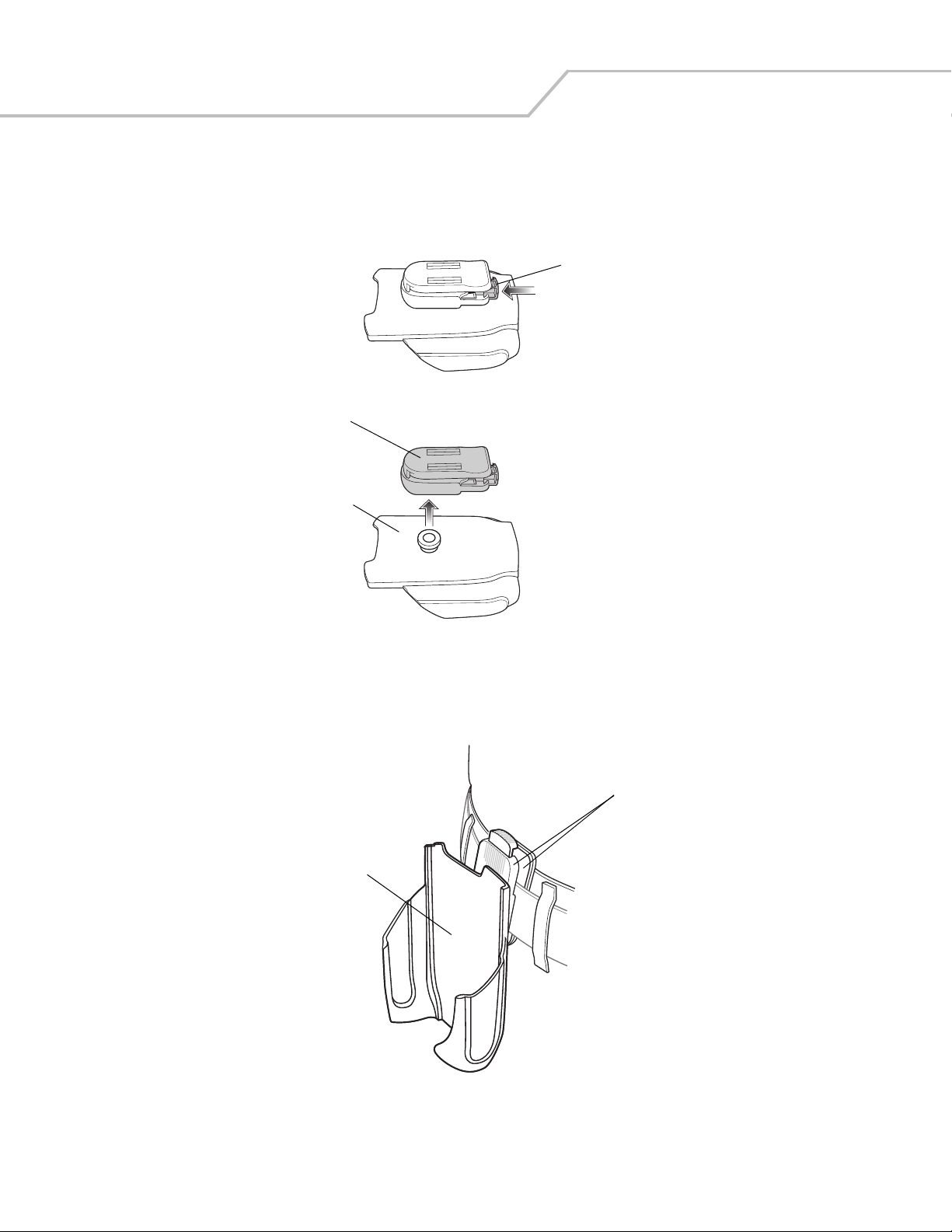
Plastic Holster
The Plastic Holster provides a holder for the mobile computer. It consists of a mobile computer holder and a detachable belt clip. Press
the release button to remove the detachable belt clip.
Figure 4-8. Plastic Holster
Pinch the clip release and attach the Plastic Holster to a belt or waist band.
Figure 4-9. Attaching the Plastic Holster
The Plastic Holster holds the mobile computer on a belt or waist band.
Detachable Belt Clip
Release Button
Mobile Computer Holder
Clip Release
Mobile Computer Holder
Accessories 4-15
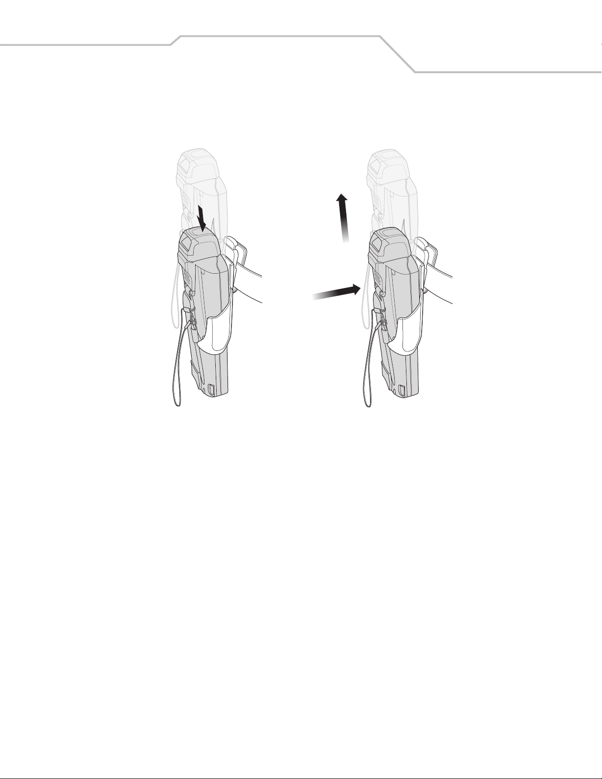
To insert the mobile computer, slide the mobile computer into the Plastic Holster with the screen facing the user.
To remove the mobile computer, press and lift to remove the mobile computer.
Figure 4-10. Insert and Remove the Mobile Computer
Insert Mobile Computer
Remove Mobile Computer
MC3000 User Guide4-16
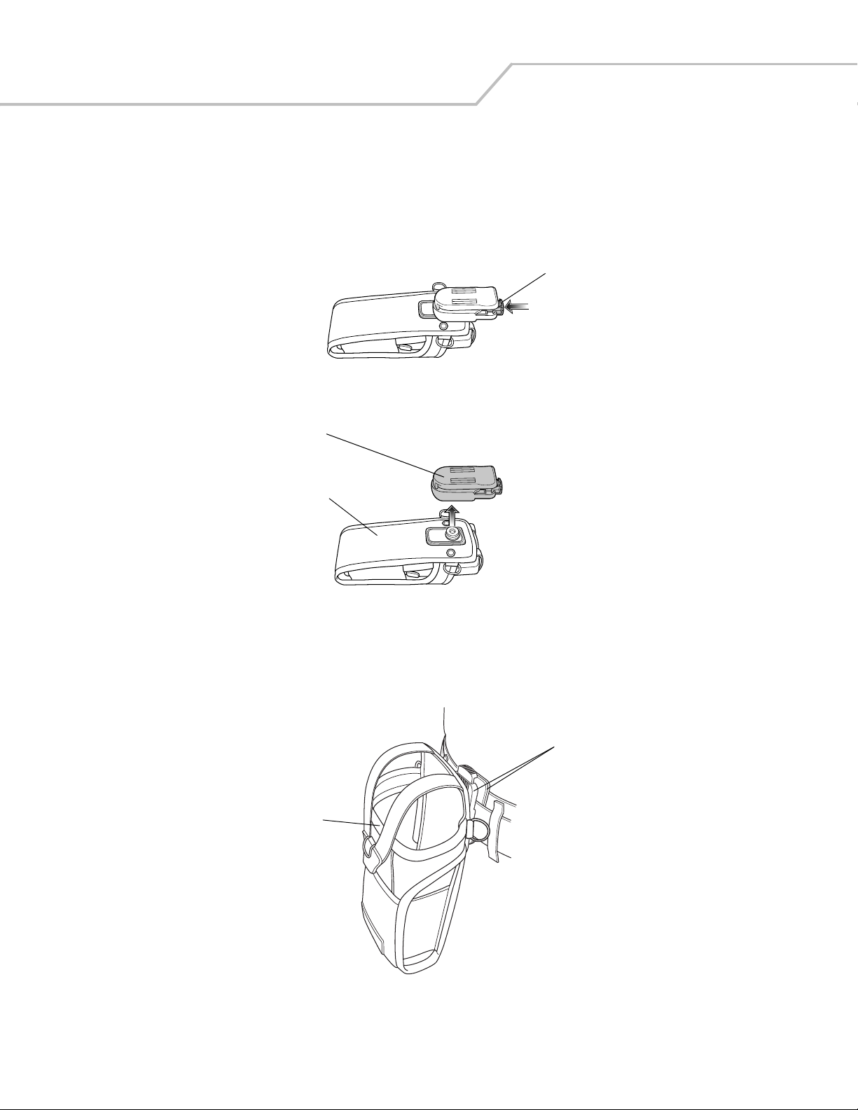
Fabric Holster
The Fabric Holster provides a soft holder for the mobile computer. It consists of a fabric mobile computer holder, a detachable shoulder
strap and a detachable belt clip. Press the release button to remove the detachable belt clip. See Figure 4-11 to remove the detachable
clip see Figure 4-12 on page 4-16 to attach the Fabric Holster to a belt and see Figure 4-13 on page 4-17 to attach the Fabric Holster
to a shoulder strap. See The Plastic Holster holds the mobile computer on a belt or waist band. on page 4-14 for instructions on
inserting and removing the mobile computer.
Figure 4-11. Fabric Holster Detachable Belt Clip
Belt Clip
Pinch the clip release and attach the Fabric Holster to a belt or waist band.
Figure 4-12. Attaching the Fabric Holster To a Belt
Detachable Belt Clip
Release Button
Mobile Computer Holder
Clip Release
Mobile Computer Holder
Accessories 4-17
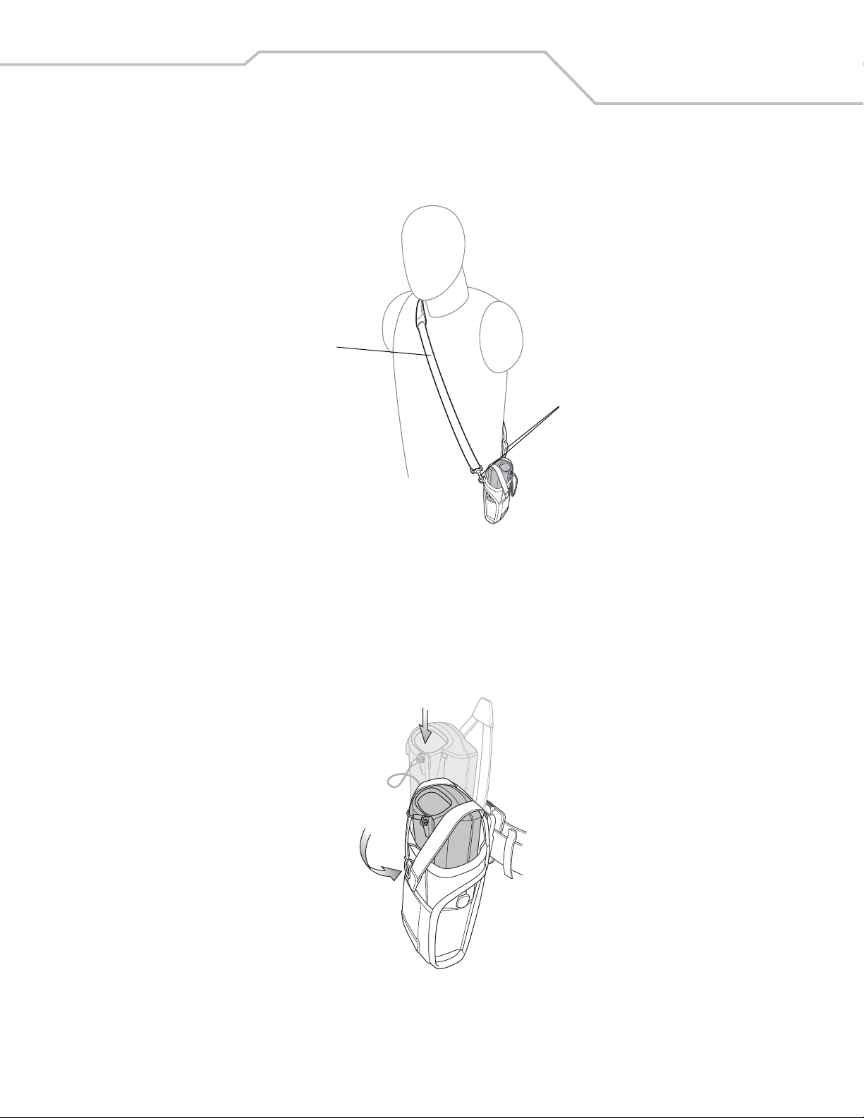
Shoulder Strap
Remove the detachable belt clip (see Figure 4-11 on page 4-16) and attach the shoulder strap.
Figure 4-13. Attach the Fabric Holster To the Shoulder Strap
The Fabric Holster holds the mobile computer on a belt or waist band.
1. To insert the mobile computer, slide the mobile computer into the Fabric Holster with the screen facing the user.
2. Pull restraining strap over mobile computer and secure in the clip.
3. To remove the mobile computer, pull down on restraining strap to release from clip and lift retaining strap clear.
4. Lift mobile computer out of Fabric Holster.
Figure 4-14. Insert and Remove the Mobile Computer
Clip Release
Shoulder Strap

MC3000 User Guide4-18
 Loading...