

Page 1
1
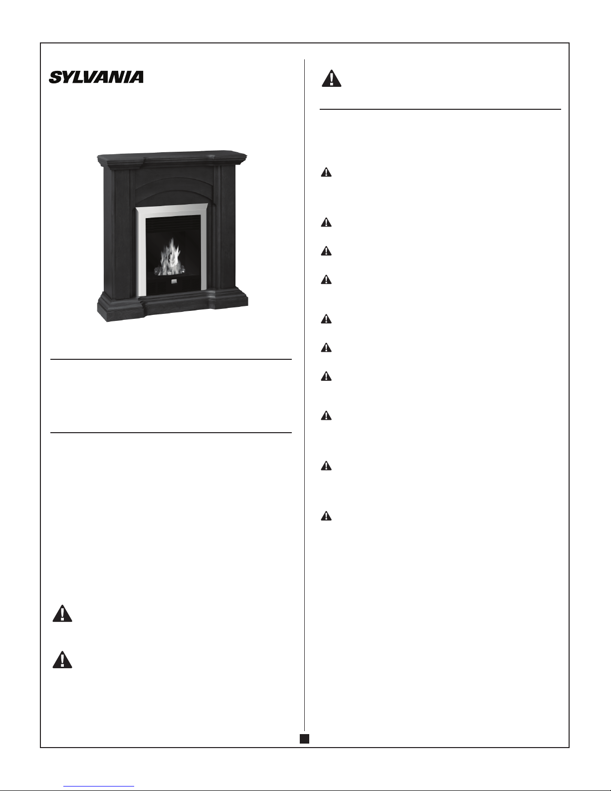
ETHONAL FIREPLACE
LANGDALE
Model: SREM320S-38C (CTC #64-3536)
INSTRUCTION MANUAL
ATTENTION:
1. Find a location for the ethonal fireplace that is protected from
direct sunlight.
IMpORTANT:
READ THIS MANUAL CAREFULLY TO LEARN HOW
TO ASSEMBLE, OPERATE AND MAINTAIN YOUR
PRODUCT PROPERLY. IT IS ESSENTIAL THAT YOU
OR ANY OTHER OPERATOR OF THE APPLIANCE
READ AND UNDERSTAND THE CONTENTS OF THIS
MANUAL BEFORE OPERATING THE APPLIANCE. THE
INFORMATION IN THIS MANUAL CAN HELP YOU AND
OTHERS AVOID INJURY AND PRODUCT DAMAGE.
STORE THIS MANUAL IN A SAFE PLACE FOR FUTURE
REFERENCE.
This manual identifies potential hazards and has special safety
messages that help you and others avoid personal injury and
even death. Danger, Warning and Caution are signal words used
to identify the level of hazard.
WARNING SIGNALS A HAZARD THAT MAY CAUSE
SERIOUS INJURY OR DEATH IF YOU DO NOT FOLLOW
THE RECOMMENDED PRECAUTIONS.
CAUTION SIGNALS A HAZARD THAT MAY CAUSE
MINOR OR MODERATE INJURY IF YOU DO NOT
FOLLOW THE RECOMMENDED PRECAUTIONS.
However, regardless of the hazard, be extremely careful.
CAUTION:
IMpORTANT SAFETY INSTRUCTIONS
If you have any problems with this unit or there are missing or
damaged parts, please call toll free: 1-800-459-4409. DO NOT
RETURN THE UNIT TO THE PLACE OF PURCHASE before calling
the toll free number above.
WARNING - DO NOT TOUCH THE FIREPLACE WHILE
IT IS BURNING. ALLOW AT LEAST 15 MINUTES TO
COOL DOWN AFTER THE FLAME IS EXTINGUISHED FOR
ANY REFILL/ RESTART/CLEANING/MAINTENANCE.
WARNING - DO NOT SMOKE WHILE HANDLING
FUEL.
WARNING - RISK OF FIRE AND BURN INJURY.
NEVER POUR FUEL INTO THE BURNING FLAME!
WARNING - ALLOW THE BURNER TO COOL DOWN
FOR AT LEAST 15 MINUTES BEFORE REFILLING. DO NOT
POUR FUEL INTO A HOT BURNER!
WARNING - KEEP CHILDREN AND ANIMALS AWAY
FROM THE FIREPLACE.
WARNING - DO NOT STORE / PLACE FLAMMABLE
GOODS CLOSE TO FIREPLACE.
WARNING - FUEL MUST BE KEPT A SAFE DISTANCE
OF AT LEAST 1M (40 IN) FROM THE FIREPLACE. DO NOT
PLACE FUEL IN FRONT OF THE FIREPLACE.
WARNING - RESTRICT THE USE OF THIS PRODUCT
TO PERSONS WHO READ, UNDERSTAND AND FOLLOW
THE WARNINGS AND INSTRUCTIONS IN THIS MANUAL
AND ON THE UNIT.
WARNING - THIS APPLIANCE HAS NOT BEEN
TESTED WITH AN UNVENTED GAS LOG SET. TO
REDUCE RISK OF FIRE OR INJURY, DO NOT INSTALL AN
UNVENTED GAS LOG SET INTO THE APPLIANCE.
WARNING - THIS FIREPLACE INSERT CANNOT BE
USED ALONE AND CANNOT BE INSTALLED IN OTHER
FIREPLACE MANTEL. FOLLOW THE INSTALLATION
INSTRUCTIONs AND USE ONLY IN THIS FIREPLACE.
Check with your insurance company, landlord or local
authorities for details and regulations before using the
fireplace.
The fireplace must only be installed on a solid wall of
non-flammable material.
The ethanol fire will use oxygen from the air inside
the room where it is operated. The room should be
well ventilated with enough oxygen and fresh air being
supplied (i.e. open windows).
The room where the fireplace is operated should not be
smaller than 44 cubic meters (1550 cubic feet). The area
of the room needs to be at least 20 square meters (215
square feet) with a ceiling height of 2.3 meter (8 feet).
SYLVANIA is a registered trademark of OSRAM SYLVANIA, used under license.
Page 2
2
It is not recommended to use more than one fireplace at a
time in one room.
Never leave a fire unattended at any time.
The fireplace is not suitable for heating purposes.
The burner and fuel must not be exposed to direct heat
such as direct sunlight and other heating sources.
Do not place any flammable material/ flammable liquid
within 1 meter (40 inches) around the fireplace. A safety
distance of at least 2 meters (80 inches) should be kept
from any window and curtain.
Avoid drafts in the room where the fireplace is located.
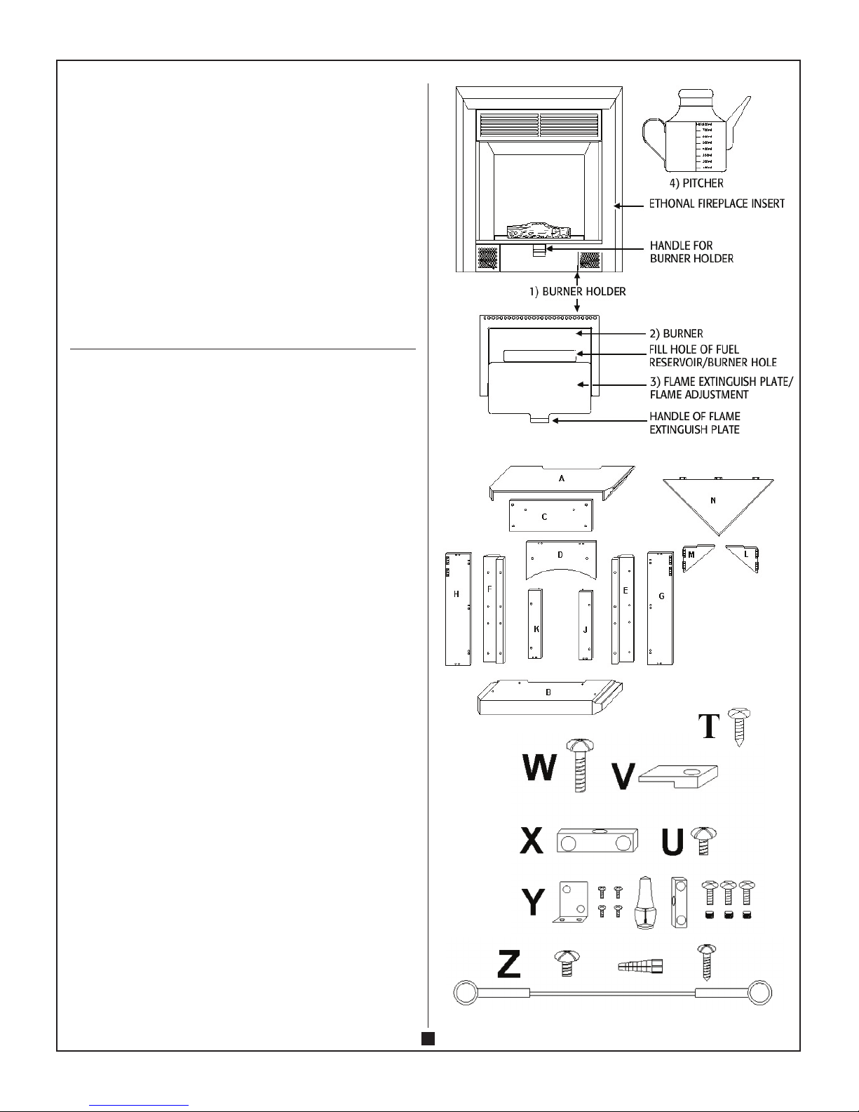
pARTS LIST:
Ethanol Insert
1) Burner holder..................................................................................... 1
2) Burner (max capacity 800 mL) ........................................................ 1
3) Flame extinguish plate (flame adjustment) ................................... 1
4) Pitcher .................................................................................................1
A) Top panel ............................................................................................1
B) Base panel ..........................................................................................1
C) Front Upper Panel ............................................................................. 1
D) Front middle panel ............................................................................1
E) Left front panel ..................................................................................1
F) Right front panel ................................................................................ 1
G) Left side panel ....................................................................................1
H) Right side panel ................................................................................-1
J) Left front small panel ........................................................................ 1
K) Right front small panel .....................................................................1
L) Left triangle support .......................................................................... 1
M) Right triangle support ......................................................................1
N) Corner Top panel ...............................................................................1
T) Mounting screws ...............................................................................6
U) Medium KD screws ........................................................................... 4
V) Mounting bracket ............................................................................. 4
W) KD screws ......................................................................................... 52
X) Plastic Connectors ........................................................................... 14
Y) SELF REPAIR SET
Touch-up repair paint (bottle) ..............................................................1
L shape bracket ....................................................................................... 2
Screws for L shape .................................................................................8
Plastic connector ..................................................................................... 1
KD screws ................................................................................................3
KD nuts ..................................................................................................... 3
Z) WALL ANCHOR SAFETY CABLE
Wall anchor .............................................................................................1
Screw for wall anchor ............................................................................1
Screw for mantel ..................................................................................... 1
Safety cable .............................................................................................1
TOOL REQUIRED: PHILLIPS HEAD SCREWDRIVER
Page 3
3
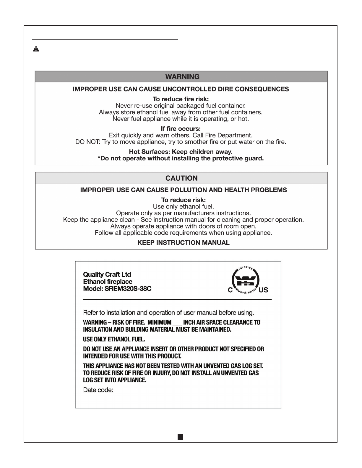
pROdUCT LAbELS
WARNING - READ, UNDERSTAND AND FOLLOW ALL
SAFETY LABELS AND MARKINGS ON THE UNIT.
Page 4

4
MANTEL ANd INSE RT ASSE MbLY:
NOTE: Place a piece of cardboard or protective sheet on the floor
in order to avoid scratching the decorative surface of your mantel
during assembly. Please DO NOT fully tighten the KD screws until
all panels are assembled.
NOTE: If the KD screw(s) do not fit during assembly, loosen
the 2 screws to adjust the Plastic Connector until the PANEL/ KD
SCREWS are able to be installed. Tighten all KD screws once all
panels are assembled.
Step 1: Attach 10 PLASTIC CONNECTORS [X] to the LEFT and
RIGHT SIDE PANELS [J and K - 5 CONNECTORS on each panel]
as shown in Fig. A. (2 pcs KD SCREWS for each CONNECTOR)
Step 2: Attach LEFT SIDE PANEL [G] to LEFT FRONT PANEL [E]
with 3 KD SCREWS. Attach RIGHT SIDE PANEL [H] to RIGHT
FRONT PANEL [F] with 3 KD SCREWS. See Fig. B.
Step 3: Attach LEFT FRONT SMALL PANEL [J] to LEFT FRONT
PANEL [E] with 2 KD SCREWS. Attach RIGHT FRONT SMALL
PANEL [K] to RIGHT FRONT PANEL [F] with 2 KD SCREWS. See
Fig. C.
Step 4: Attach PANELS [E, G, and J] and PANELS [F, H and K] to
BASE [B] with 4 KD SCREWS. See Fig. D.
Step 5: Attach 2 PLASTIC CONNECTORS to FRONT UPPER PANEL
[C] with 4 KD SCREWS (2 KD SCREWS for each plastic connector).
Attach FRONT MIDDLE PANEL [D] to FRONT UPPER PANEL [C]
with 2 KD SCREWS. See Fig. E.
Step 6: Attach FRONT UPPER PANEL [C] and FRONT MIDDLE
PANEL [D] to LEFT and RIGHT FRONT PANELS with 4 KD
SCREWS (2 KD SCREWS at each sides). See Fig. F.
Page 5

5
Step 7: Attach LEFT TRIANGLE SUPPORT [L] and RIGHT TRIANGLE
SUPPORT [M] on LEFT and RIGHT SIDE PANEL [G and H]. See
Fig. G.
Do not attach TRIANGLE SUPPORTS [L and M] and CORNER TOP
PANEL [N] unless the fireplace is to be installed in the corner.
Step 8: Connect CORNER TOP PANEL [N] to TOP PANEL [A] with 6
MOUNTING SCREWS [T]. See Fig. H.
Step 9: Install TOP PANEL [A] to the unit with 4 KD SCREWS as
shown in Fig. J.
Corner panel shall be fully opened if attached and fireplace shall
be installed at corner only.
Step 10: Place the insert in the back of mantel on floor. Carefully
lift the INSERT into the mantel until the trim is against to mantel.
See Fig K.
Step 11: Attach 4 MOUNTING BRACKETS with 4 MEDIUM KD
SCREWS at the bottom of insert. (2 MOUNTING BRACKETS at
each side). See Fig L.
Page 6

6
WALL ANCHOR SAFETY CAbLE
CAUTION - THIS CABLE MAY REDUCE POSSIBLE
RISK OF INJURY IF THE FIREPLACE IS IMPROPERLY
HANDLED, BUT IS NOT A SUBSTITUTE FOR PROPER
ADULT SUPERVISION. CHILDREN SHOULD NOT BE LEFT
UNATTENDED NEAR ANY ETHONAL FIREPLACE.
The use of WALL ANCHOR SAFETY CABLE is highly
recommended in order to reduce the risk of the fireplace being
tipped over accidentally.
1) Drill a 5/16” (8mm) hole in the wall. Insert the PLASTIC WALL
ANCHOR into the hole and gently tap until the flange on the
anchor is against the wall surface.
2) Position the back edge of the mantel close to the wall.
3) Attach the SAFETY CABLE to the mantle using the SCREW FOR
MANTLE. See fig. M.
4) Use the SCREW FOR WALL to attach the other end of SAFETY
CABLE to the wall.
5) Make sure all screws are tight.
STARTING Up
1) Pull the BURNER HOLDER HANDLE out towards you and
then open the BURNER by sliding the FLAME EXTINGUISH/
ADJUSTMENT PLATE until it is fully open and you can see fuel
reservoir (FILL HOLE). See Fig. 1.
2) Fill the fuel reservoir with ethanol through the top opening
(FILL HOLE ). See Fig 2.
WARNING – DO NOT EXCEED MAXIMUM FUEL
CAPACITY 800ML
3) Push the BURNER HOLDER & BURNER into fireplace until the
burner holder is completely inserted. See Fig 3.
Page 7

7
4) Light the ethanol using lighter through the hole on front glass.
See Fig. 4.
5) The flame will ignite slowly and grow to full size in 5 to 10
minutes (Keep the FLAME EXTINGUISH/ADJUSTMENT PLATE
open during this time).
6) After 10 minutes, adjust the flame by slightly closing the
opening of burner using the FLAME EXTINGUISH/ADJUSTMENT
PLATE. See Fig. 5.
7) To extinguish the flame - close the burner by pushing the
FLAME EXTINGUISH/ADJUSTMENT PLATE all the way in.
See Fig. 6.
CAUTION - IN CASE OF ANY EMERGENCY, FIRE
HAZARD OR OVERHEATING, THE FLAME EXTINGUISH
PLATE SERVES AS A SAFETY DEVICE TO EXTINGUISH THE
FLAME.
ExTI NGUISHING THE FLAME
WARNING - NEVER EXTINGUISH THE FLAME WITH
WATER!
WARNING - RISK OF FIRE AND BURNS, DO NOT
POUR OUT THE ETHANOL WHILE IT IS HOT.
WARNING - ETHANOL IS A FLAMMABLE LIQUID AND
SHOULD BE HANDLED CAREFULLY.
1) Let the fuel burn out completely if possible. This prevents
alcohol odours left in the reservoir and deflagration when
reigniting (before refill or closing down).
2) If you wish to extinguish the flame before the fuel is
completely burned out, push the front handle of burner until
opening of burner is completely closed. It is not recommended
to leave ethanol inside the fuel reservoir while it is not in use.
If the flame will not fully extinguish immediately. Leave the
burner closed. Do not blow air into the burner - It will not help to
extinguish the flame but will actually cause the flame to become
bigger by increasing the combustion. Wait for flame to extinguish
before leaving flame unattended.
REFILLING
WARNING - RISK OF FIRE AND BURNS. DO NOT ADD
FUEL INTO A BURNING FLAME.
WARNING - RISK OF FIRE AND BURNS. DO NOT ADD
FUEL INTO HOT BURNER.
1) After the flame is extinguished, allow the burner to cool down
at least 15 minutes before refilling.
2) When the burner is cooled down, follow the steps in
STARTING UP section to restart.
CLEAN ING ANd MAINTENANCE
WARNING - THE BURNER MUST BE EXTINGUISHED
AND COMPLETELY COOLED DOWN BEFORE ANY
CLEANING OR MAINTENANCE CAN BE CARRIED OUT.
1) Remove the burner from the drawer.
2) Clean the burner with a damp cloth.
3) Do not pour water into fuel reservoir. It causes moisture/
water accumulation inside and affects the effectiveness of burner.
4) Clean the glass and other areas of fireplace with a damp cloth.
FUEL STORAGE
WARNING - STORE FUEL AWAY FROM CHILDREN
AND ANIMALS. KEEP FUEL CONTAINER COMPLETELY
CLOSED WHILE NOT IN USE.
1) Do not store more than 5 liters/1.3 gallon of flammable liquid
in your home.
Page 8

8
2) Store fuel at room temperature to facilitate ignition.
3) The burner and fuel must not be exposed to direct heat such
as direct sunlight and other heating sources.
REpAIR SET
TOUCH-Up REpAIR pAINT
1. Paint directly on the mantel unit if necessary. Fig. A.
REpAIRS
If any problems are found with the original parts during mantel
assembly such as the panels cannot be installed with the plastic
connector. Try to solve by one of the following methods.
Tools required: Electric drill, drill bits 3/4 inches (10 mm) or
1/16 inches (2 mm), pencil, hammer, Philips screwdriver, safety
goggles and gloves (if necessary).
WARNING: WEAR EYE PROTECTION BEFORE YOU
START DRILLING.
OPTION 1:
Use the spare KD NUTS, KD SCREWS and PLASTIC
CONNECTORS.
1. Place the PLASTIC CONNECTOR on the mantel unit and mark
the drill-holes as shown in Fig. B.
2. Drill the holes with diameter 3/4 inches (10 mm) and depth
3/4 inches
(10mm) on the mantel. Each Plastic Connector needs
3 holes. See Fig. C.
3. Gently install the KD NUTS into the drilled-holes with
hammer as shown in Fig. D.
4. Attach the PLASTIC CONNECTOR and lock in place with KD
SCREWS as shown in Fig. E.
OPTION 2:
Use the SMALL L-BRACKETS and SCREWS
1. Place the SMALL L-BRACKET to the unit as shown and mark
the drill-holes on the mantel as shown in Fig. F.
Page 9

9
2. Drill the holes with diameter 1/16 inches (2 mm) and depth
5/16 inches (8mm) on the mantel. Each SMALL L-BRACKET
needs 4 holes. See Fig. G.
3. Attach the SMALL L-BRACKET and lock in place with SCREWS
as shown in Fig. H
1 YEAR HOME USE WARRANY
Quality Craft warrants this product for one year against defects
in material or workmanship when used for normal residential
purposes.
If the unit should fail to operate correctly within one year from
the date of purchase, call customer service at 1-800-459-4409
(EST).
Before you make your call please make sure you have 1] the
model number of your product; 2] proof of sale; 3] details
regarding the problem; 4] your contact information ready.
We will, at our discretion either repair or replace the unit. It will
have to be returned to us freight prepaid and we will return the
repaired or replaced unit to you freight prepaid. The company’s
sole obligation is to repair or replace the unit.
This warranty is void if in the opinion of Quality Craft, the
unit has been tampered with, altered, misused, damaged,
abused or used with the wrong power source. The warranty
is for homeowner use only and does not cover units used in
commercial situations.
This warranty covers product defects only. Quality Craft is
not liable for indirect, incidental or consequential damages
in connection with the use of this product, including any
cost or expense of providing substitute equipment or service
during reasonable periods of malfunction or non-use pending
completion of repairs under this warranty.
Imported by
Quality Craft Ltd.
Laval, Quebec, Canada H7S 2G7
1-800-459-4409 (EST)
www.qualitycraft.com
Made in China
 Loading...