

Suzuki de reparatie www.manualedereparatie.info User Manual
GSF650
/
S
FOREWORD
This manual contains an introductory description on
the SUZUKI GSF650/S and procedures for its
inspection/service and overhaul of its main components.
Other information considered as generally known is
not included.
Read the GENERAL INFORMATION section to
familiarize yourself with the motorcycle and its maintenance. Use this section as well as other sections
to use as a guide for proper inspection and service.
This manual will help you know the motorcycle better so that you can assure your customers of fast
and reliable service.
*
This manual has been prepared on the basis of
the latest specifications at the time of publication. If modifications have been made since
then, differences may exist between the content
of this manual and the actual motorcycle.
* Illustrations in this manual are used to show the
basic principles of operation and work procedures. They may not represent the actual
motorcycle exactly in detail.
*
This manual is written for persons who have
enough knowledge, skills and tools, including
special tools, for servicing SUZUKI motorcycles. If you do not have the proper knowledge
and tools, ask your authorized SUZUKI motorcycle dealer to help you.
GROUP INDEX
GENERAL INFORMATION
PERIODIC MAINTENANCE
ENGINE
FUEL SYSTEM
CHASSIS
ELECTRICAL SYSTEM
SERVICING INFORMATION
1
2
3
4
5
6
7
!
Inexperienced mechanics or mechanics
without the proper tools and equipment
may not be able to properly perform the
services described in this manual.
Improper repair may result in injury to the
mechanic and may render the motorcycle
unsafe for the rider and passenger.
© COPYRIGHT SUZUKI MOTOR CORPORATION 2004
HOW TO USE THIS MANUAL
TO LOCATE WHAT YOU ARE LOOKING FOR:
1. The text of this manual is divided into sections.
2. The section titles are listed in the GROUP INDEX.
3. Holding the manual as shown at the right will allow you to find
the first page of the section easily.
4. The contents are listed on the first page of each section to
help find the item and page you need.
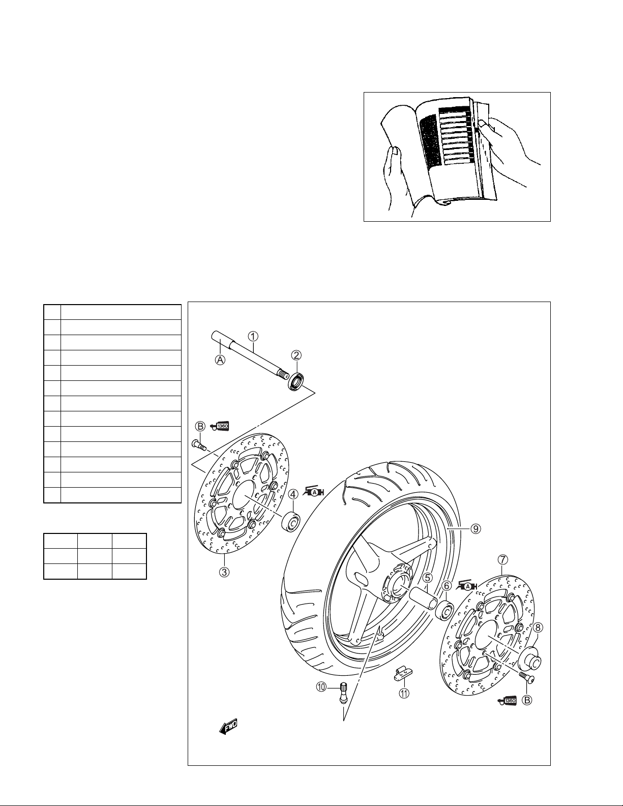
COMPONENT PARTS AND WORK TO BE DONE
Under the name of each system or unit, is its exploded view. Work instructions and other service information
such as the tightening torque, lubricating points and locking agent points, are provided.
Example: Front wheel
1 Front axle
2 Dust seal
3 Brake disc (RH)
4 Bearing (RH)
5 Spacer
6 Bearing (LH)
7 Brake disc (LH)
8 Collar
9 Front wheel
0 Air bleeder valve
A Balancer
A Front axle
B Brake disc bolt
"
ITEM N·m
A 65 6.5
B 23 2.3
kgf-m
SYMBOL
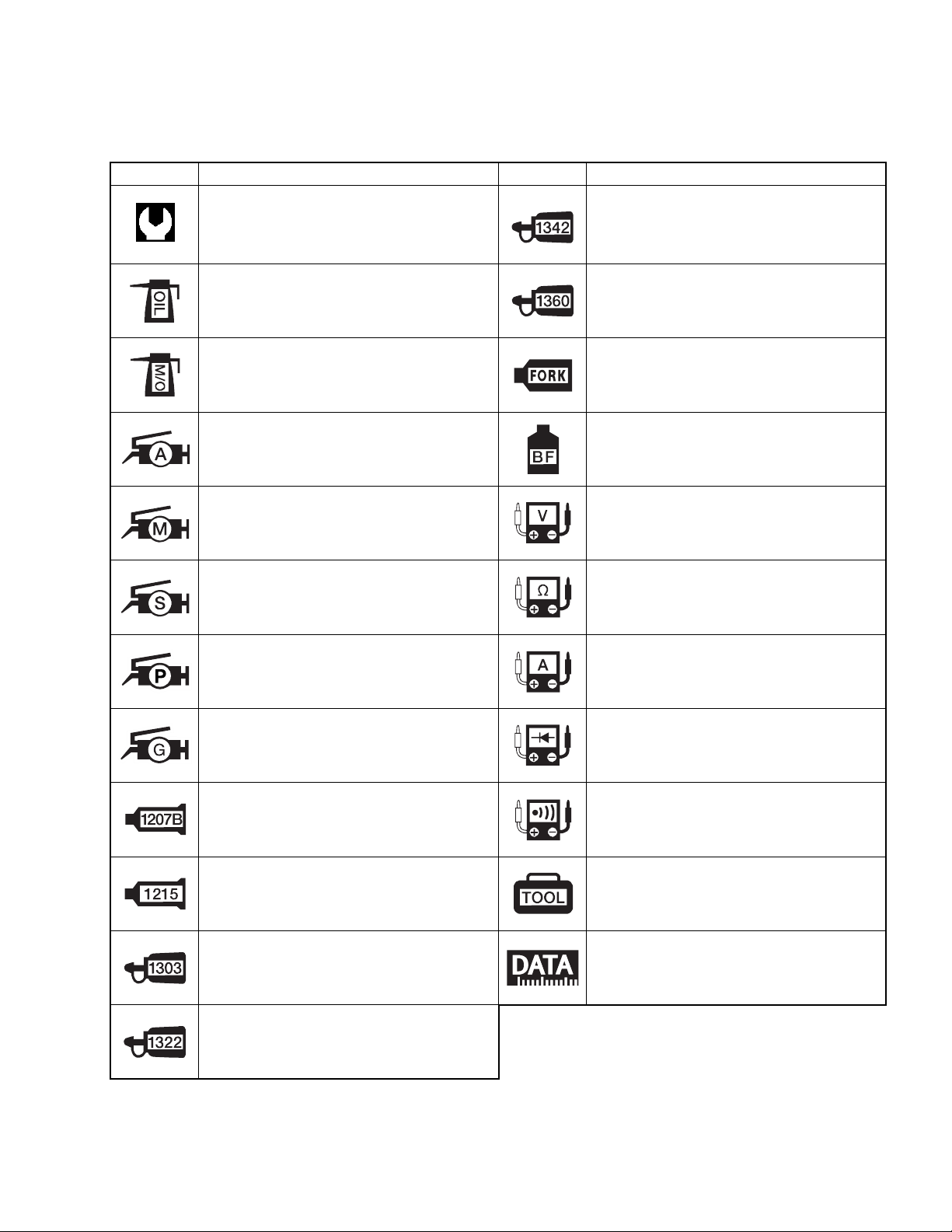
Listed in the table below are the symbols indicating instructions and other information necessary for servicing. The meaning of each symbol is also included in the table.
SYMBOL DEFINITION SYMBOL DEFINITION
Torque control required.
Data beside it indicates specified
torque.
Apply oil.
Use engine oil unless otherwise specified.
Apply molybdenum oil solution (mixture
of engine oil and SUZUKI MOLY PASTE
in a ratio of 1:1).
Apply SUZUKI SUPER GREASE “A”.
99000-25010
Apply SUZUKI MOLY PASTE.
99000-25140
Apply SUZUKI SILICONE GREASE.
99000-25100
Apply THREAD LOCK “1342”.
99000-32050
Apply THREAD LOCK SUPER “1360”.
99000-32130
Use fork oil.
99000-99044-10G
Apply or use brake fluid.
Measure in voltage range.
Measure in resistance range.
Apply PBC GREASE.
99000-25110
Apply THERMO-GREASE.
99000-59029
Apply SUZUKI BOND “1207B”.
99000-31140
Apply SUZUKI BOND “1215”.
99000-31110
Apply THREAD LOCK SUPER “1303”.
99000-32030
Apply THREAD LOCK SUPER “1322”.
99000-32110
Measure in current range.
Measure in diode test range.
Measure in continuity test range.
Use special tool.
Indication of service data.
GENERAL INFORMATION 1-1
GENERAL INFORMATION
CONTENTS
WARNING/CAUTION/NOTE .........................................................................1- 2
GENERAL PRECAUTIONS ...........................................................................1- 2
SUZUKI GSF650 (2005-MODEL) ..................................................................1- 4
SUZUKI GSF650S (2005-MODEL) ................................................................1- 4
SERIAL NUMBER LOCATION ......................................................................1- 4
FUEL AND OIL RECOMMENDATION ..........................................................1- 5
FUEL (For Canada) ...............................................................................1- 5
FUEL (For other countries) ..................................................................1- 5
ENGINE OIL ...........................................................................................1- 5
BRAKE FLUID ........................................................................................1- 5
FRONT FORK OIL .................................................................................1- 5
BREAK-lN PROCEDURES ...........................................................................1- 6
CYLINDER IDENTIFICATION .......................................................................1- 6
INFORMATION LABELS ...............................................................................1- 7
SPECIFICATIONS .........................................................................................1- 8
1
COUNTRY AND AREA CODES
The following codes stand for the applicable country(-ies) and area(-s).
CODE COUNTRY OR AREA
E-02
E-19
E-28
England (UK)
European markets
Canada
1-2 GENERAL INFORMATION
WARNING/CAUTION/NOTE
Please read this manual and follow its instructions carefully. To emphasize special information, the symbol
and the words WARNING, CAUTION and NOTE have special meanings. Pay special attention to the messages highlighted by these signal words.
!
Indicates a potential hazard that could result in death or injury.
"
Indicates a potential hazard that could result in motorcycle damage.
NOTE:
Indicates special information to make maintenance easier or instructions clearer.
Please note, however, that the warnings and cautions contained in this manual cannot possibly cover all
potential hazards relating to the servicing, or lack of servicing, of the motorcycle. In addition to the WARNINGS and CAUTIONS stated, you must use good judgement and basic mechanical safety principles. If you
are unsure about how to perform a particular service operation, ask a more experienced mechanic for
advice.
GENERAL PRECAUTIONS
!
* Proper service and repair procedures are important for the safety of the service mechanic and
the safety and reliability of the motorcycle.
* When 2 or more persons work together, pay attention to the safety of each other.
* When it is necessary to run the engine indoors, make sure that exhaust gas is forced out-
doors.
* When working with toxic or flammable materials, make sure that the area you work in is well-
ventilated and that you follow all of the material manufacturer’s instructions.
* Never use gasoline as a cleaning solvent.
* To avoid getting burned, do not touch the engine, engine oil, oil cooler and exhaust system
until they have cooled.
* After servicing the fuel, oil, exhaust or brake systems, check all lines and fittings related to
the system for leaks.
GENERAL INFORMATION 1-3
"
* If parts replacement is necessary, replace the parts with Suzuki Genuine Parts or their equiva-
lent.
* When removing parts that are to be reused, keep them arranged in an orderly manner so that
they may be reinstalled in the proper order and orientation.
* Be sure to use special tools when instructed.
* Make sure that all parts used in reassembly are clean. Lubricate them when specified.
* Use the specified lubricant, bond or sealant.
* When removing the battery, disconnect the negative cable first and then the positive cable.
When reconnecting the battery, connect the positive cable first and then the negative cable,
and replace the terminal cover on the positive terminal.
* When performing service to electrical parts, if the service procedures not require use of bat-
tery power, disconnect the negative cable the battery.
* When tightening the cylinder head and case bolts and nuts, tighten the larger sizes first.
Always tighten the bolts and nuts diagonally from the inside working out and to the specified
tightening torque.
* Whenever you remove oil seals, gaskets, packing, O-rings, locking washers, self-locking
nuts, cotter pins, circlips and certain other parts as specified, be sure to replace them with
new ones. Also, before installing these new parts, be sure to remove any left over material
from the mating surfaces.
* Never reuse a circlip. When installing a new circlip, take care not to expand the end gap larger
than required to slip the circlip over the shaft. After installing a circlip, always ensure that it is
completely seated in its groove and securely fitted.
* Use a torque wrench to tighten fasteners to the specified torque. Wipe off grease and oil if a
thread is smeared with them.
* After reassembling, check parts for tightness and proper operation.
* To protect the environment, do not unlawfully dispose of used motor oil, engine coolant and
other fluids: batteries and tires.
* To protect Earth’s natural resources, properly dispose of used motorcycle and parts.
1-4 GENERAL INFORMATION
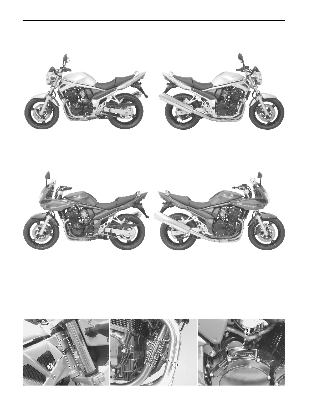
SUZUKI GSF650 (2005-MODEL)
* Difference between photographs and actual motorcycles may exist depending on the markets.
SUZUKI GSF650S (2005-MODEL)
* Difference between photographs and actual motorcycles may exist depending on the markets.
SERIAL NUMBER LOCATION
The frame serial number or V.I.N. (Vehicle Identification Number)
steering head pipe and frame down tube. The engine serial number
crankcase. These numbers are required especially for registering the machine and ordering spare parts.
1 is stamped on the right side of the
2 is located on the right side of the
GENERAL INFORMATION 1-5
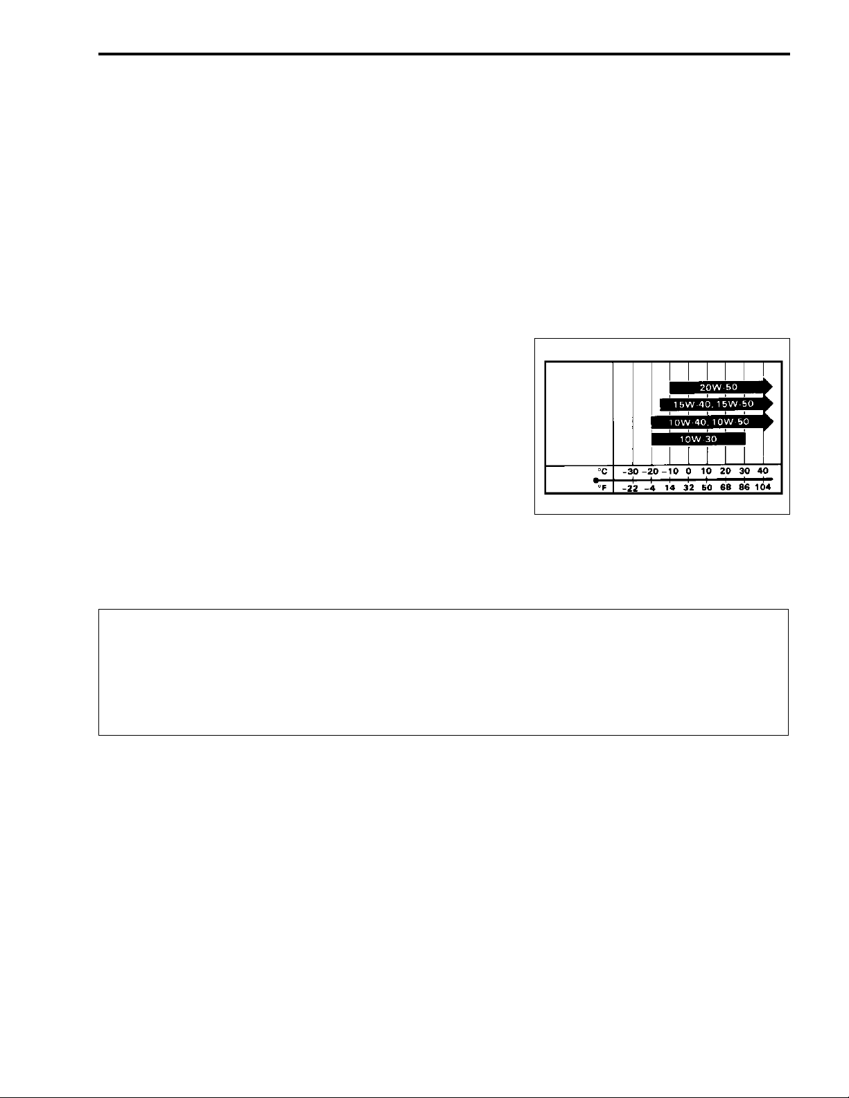
MULTIGRADE
TEMP.
FUEL AND OIL RECOMMENDATION
FUEL (For Canada)
Use only unleaded gasoline of at least 87 pump octane (R/2 + M/2) or 91 octane or higher rated by the
research method.
Gasoline containing MTBE (Methyl Tertiary Butyl Ether), less than 10% ethanol, or less than 5% methanol
with appropriate cosolvents and corrosion inhibitor is permissible.
FUEL (For other countries)
Gasoline used should be graded 91 octane (Research Method) or higher. An unleaded gasoline is recommended.
ENGINE OIL
Oil quality is a major contributor to your engine’s performance
and life. Always select good quality engine oil. Use SF/SG or
SH/SJ with JASO MA in API (American Petroleum Institute)
classification.
Suzuki recommends the use of SAE 10W-40 engine oil. If SAE
10W-40 engine oil is not available, select an alternative according to the following chart.
BRAKE FLUID
Specification and classification: DOT 4
!
Since the brake system of this motorcycle is filled with a glycol-based brake fluid by the manufacturer, do not use or mix different types of fluid such as silicone-based and petroleum-based
fluid for refilling the system, otherwise serious damage will result.
Do not use any brake fluid taken from old or used or unsealed containers.
Never re-use brake fluid left over from a previous servicing, which has been stored for a long
period.
FRONT FORK OIL
Use fork oil #10 or equivalent fork oil.
1-6 GENERAL INFORMATION
BREAK-lN PROCEDURES
During manufacture only the best possible materials are used and all machined parts are finished to a very
high standard but it is still necessary to allow the moving parts to “BREAK-IN” before subjecting the engine
to maximum stresses. The future performance and reliability of the engine depends on the care and restraint
exercised during its early life. The general rules are as follows.
• Keep to these break-in engine speed limits:
Initial 800 km : Below 6 000 r/min
Up to 1 600 km : Below 9 000 r/min
Over 1 600 km : Below 12 000 r/min
• Upon reaching an odometer reading of 1 600 km you can subject the motorcycle to full throttle operation.
However, do not exceed 12 000 r/min at any time.
CYLINDER IDENTIFICATION
The four cylinders of this engine are identified as No. 1, 2, 3 and No. 4 cylinder, as counted from left to right
(as viewed by the rider on the seat).
#1
#2
#3
#4
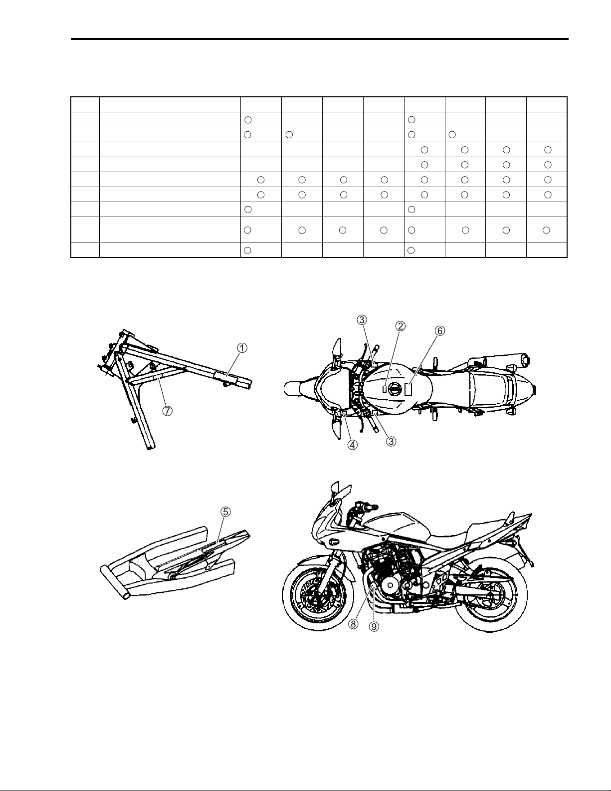
INFORMATION LABELS
GENERAL INFORMATION 1-7
No. Label name
1 Information label
2 Fuel caution label
3 Screen label
4 Warning steering label
5 Tire information label
6 General warning label
7 ICES Canada label
8 I.D. plate
9 Safety plate
GSF650 GSF650A GSF650U
E-28
E-02 E-02 E-02 E-02
E-28 E-28
Except
E-28
E-28 E-28
GSF650UA
GSF650S
E-28
Except
E-28
GSF600SA GSF650SU
GSF650SUA

1-8 GENERAL INFORMATION
SPECIFICATIONS
DIMENSIONS AND DRY MASS
Overall length....................................................... 2 110 mm
Overall width ........................................................ 770 mm
Overall height....................................................... 1 085/1 095 mm .........Low/High ..................GSF650
1 225 mm .....................................................GSF650S
Wheelbase ........................................................... 1 440 mm
Ground clearance ................................................ 130 mm
Seat height........................................................... 770/790 mm ...........Low/High
Dry mass .............................................................. 201 kg........................................................GSF650
204 kg........................................................GSF650S
ENGINE
Type ..................................................................... Four-stroke, air-cooled, DOHC
Number of cylinders ............................................. 4
Bore ..................................................................... 65.5 mm
Stroke................................................................... 48.7 mm
Displacement ....................................................... 656 cm
Compression ratio ................................................ 10.5 : 1
Carburetor............................................................ KEIHIN CVR32
Air cleaner............................................................ Non-woven fabric element
Starter system...................................................... Electric
Lubrication system............................................... Wet sump
Idle speed ............................................................ 1 200 ± 100 r/min
3
DRIVE TRAIN
Clutch................................................................... Wet multi-plate type
Transmission........................................................ 6-speed constant mesh
Gearshift pattern .................................................. 1-down, 5-up
Primary reduction ratio......................................... 1.744 (75/43)
Gear ratios, Low ................................................ 3.083 (37/12)
2nd................................................. 2.062 (33/16)
3rd ................................................. 1.647 (28/17)
4th.................................................. 1.400 (28/20)
5th.................................................. 1.227 (27/22)
Top ................................................ 1.095 (23/21)
Final reduction ratio ............................................. 3.133 (47/15)
Drive chain ........................................................... RKFS50SMOZ1, 112 links

GENERAL INFORMATION 1-9
CHASSIS
Front suspension................................................. Telescopic, coil spring, oil damped
Rear suspension ................................................. Link type, coil spring, oil damped
Front suspension stroke...................................... 130 mm
Rear wheel travel ................................................ 126 mm
Caster.................................................................. 26°
Trail ..................................................................... 108 mm
Steering angle ..................................................... 35° (right & left)
Turning radius ..................................................... 2.8 m
Front brake.......................................................... Disc brake, twin
Rear brake .......................................................... Disc brake
Front tire size ...................................................... 120/70ZR17M/C (58W), tubeless
Rear tire size ....................................................... 160/60ZR17M/C (69W), tubeless
ELECTRICAL
Ignition type......................................................... Electronic ignition (Transistorized)
Ignition timing ...................................................... 10° B.T.D.C. at 1 200 r/min
Spark plug ........................................................... NGK CR8EK or DENSO U24ETR
Battery ................................................................. 12 V 28.8 kC (8 Ah)/10 HR
Generator ............................................................ Three-phase A.C. generator
Main fuse............................................................. 30 A
Fuse .................................................................... 10/15/15/10/10 A
Headlight ............................................................. 12 V 60/55 W H4 ......................................... GSF650
12 V 55 W H7: Upper and Lower beam....... GSF650S
Parking or city light .............................................. 12 V 5 W...................................................... GSF650
12 V 5 W × 2 ................................................ GSF650S
Turn signal light ................................................... 12 V 21 W
Brake light/Taillight .............................................. 12 V 21/5 W
Speedometer light ............................................... LED
Tachometer light ................................................. LED
Neutral indicator light .......................................... LED
High beam indicator light..................................... LED
Turn signal indicator light .................................... LED
Oil pressure indicator light................................... LED
CAPACITIES
Fuel tank, including reserve............................... 20.0 L
reserve .............................................. 4.5 L
Engine oil, oil change ......................................... 3 300 ml
with filter change............................... 3 500 ml
overhaul ............................................ 4 600 ml
These specifications are subject to change without notice.
PERIODIC MAINTENANCE 2-1
PERIODIC MAINTENANCE
CONTENTS
PERIODIC MAINTENANCE SCHEDULE .......................................................2- 2
PERIODIC MAINTENANCE CHART .....................................................2- 2
LUBRICATION POINTS .........................................................................2- 3
MAINTENANCE AND TUNE-UP PROCEDURES ..........................................2- 4
VALVE CLEARANCE ............................................................................2- 4
SPARK PLUGS ......................................................................................2- 6
EXHAUST PIPE BOLTS AND MUFFLER BOLTS ................................2- 7
AIR CLEANER .......................................................................................2- 8
ENGINE OIL AND OIL FILTER ..............................................................2- 9
FUEL LINE .............................................................................................2-11
ENGINE IDLE SPEED ............................................................................2-11
THROTTLE CABLE PLAY .....................................................................2-11
CARBURETOR SYNCHRONIZATION ..................................................2-12
PAIR (AIR SUPPLY) SYSTEM ...............................................................2-12
FUEL FILTER .........................................................................................2-12
CLUTCH CABLE PLAY .........................................................................2-12
DRIVE CHAIN .........................................................................................2-13
BRAKES .................................................................................................2-15
TIRES .....................................................................................................2-18
STEERING ..............................................................................................2-18
FRONT FORKS ......................................................................................2-19
REAR SUSPENSION .............................................................................2-19
CHASSIS BOLTS AND NUTS ...............................................................2-20
COMPRESSION PRESSURE CHECK ............................................................2-22
COMPRESSION TEST PROCEDURE ...................................................2-22
OIL PRESSURE CHECK .................................................................................2-23
OIL PRESSURE TEST PROCEDURE ...................................................2-23
2
6
2-2 PERIODIC MAINTENANCE
PERIODIC MAINTENANCE SCHEDULE
The chart below lists the recommended intervals for all the required periodic service work necessary to keep
the motorcycle operating at peak performance and economy. Maintenance intervals are expressed in terms
of kilometers and months, and are dependant on whichever comes first.
NOTE:
More frequent servicing may be performed on motorcycles that are used under severe conditions.
PERIODIC MAINTENANCE CHART
Interval
Item
Air cleaner element – I I R I
Exhaust pipe bolts and muffler bolts
Valve clearance I – I – I
Spark plugs – I R I R
Fuel line –IIII
Fuel filter – I R I R
Engine oil RRRRR
Engine oil filter R – – R –
Idle speed IIIII
Throttle cable play IIIII
Throttle valve synchronization – – I – I
PAIR (air supply) system – – I – I
Clutch cable play –IIII
Drive chain IIIII
Brakes IIIII
Brake hoses –IIII
Brake fluid –IIII
Tires –IIII
Steering I–I–I
Front forks ––I–I
Rear suspension ––I–I
Chassis bolts and nuts
km 1 000
months2 12243648
T
TTTTT
6 000 12 000 18 000 24 000
–
Clean and lubricate every 1 000 km.
Replace every 4 years.
Replace every 2 years.
T
–
T
NOTE:
I = Inspect and clean, adjust, replace or lubricate as necessary
R = Replace
T = Tighten
PERIODIC MAINTENANCE 2-3
LUBRICATION POINTS
Proper lubrication is important for smooth operation and long life of each working part of the motorcycle.
Major lubrication points are indicated below.
1 Brake lever holder and throttle cables
2 Brake pedal pivot and right footrest pivot
3 Clutch lever holder and clutch cable
4 Side-stand pivot and spring hook
NOTE:
* Before lubricating each part, clean off any rusty spots and wipe off any grease, oil, dirt or grime.
* Lubricate exposed parts which are subject to rust, with a rust preventative spray whenever the motorcycle
has been operated under wet or rainy conditions.
5 Gearshift pivot and left footrest pivot
6 Center stand pivot and spring hook
7 Drive chain
2-4 PERIODIC MAINTENANCE
IN. EX.
MAINTENANCE AND TUNE-UP PROCEDURES
This section describes the servicing procedures for each item in
the Periodic Maintenance Chart.
VALVE CLEARANCE
Inspect initially at 1 000 km (1 month) and every 12 000
km (24 months).
• Remove the fuel tank. (!4-3)
• Remove the frame head covers. (GSF650 !5-5)
• Remove the cowling. (GSF650S !5-5)
• Remove the PAIR valve. (!3-97)
• Remove all the spark plugs.
• Remove the cylinder head cover and signal generator cover.
(!3-12 and -13)
The valve clearance specification is different for both intake and
exhaust valves.
Valve clearance adjustment must be checked and adjusted 1) at
the time of periodic inspection, 2) when the valve mechanism is
serviced, and 3) when the camshafts are removed for servicing.
" Valve clearance (when cold):
IN.: 0.10 – 0.15 mm
EX.: 0.18 – 0.23 mm
NOTE:
* The camshafts must be at positions
or adjust the valve clearance. Clearance readings should not
be taken with the camshafts in any other position than the
ones shown.
* The valve clearance should only be checked when the engine
is cold.
* Turn the crankshaft clockwise using a 19-mm wrench. Make
sure that all of the spark plugs have been removed.
• Turn the crankshaft clockwise and align the “T” mark on the
signal generator rotor with the center of the pickup coil. Also,
position the notches
shown. Then, measure the following valve clearance
Cylinder #1: Intake and exhaust valve clearance
Cylinder #2: Exhaust valve clearance
Cylinder #3: Intake valve clearance
1 on the right end of each camshaft as
A or
B, in order to check
C:
• Insert the thickness gauge between the valve stem end and
adjusting screw on the rocker arm. If the clearance is out of
specification, hold the locknut with a wrench and use the special tool to adjust the clearance.
# 09900-20803: Thickness gauge
09917-14910: Valve adjuster driver
$
PERIODIC MAINTENANCE 2-5
Both the right and left valve clearances should be as
closely as possible.
• Turn the crankshaft clockwise 360° (one full rotation) and
align the “T” mark on the signal generator rotor with the center
of the pickup coil. Also, position the notches
end of each camshaft as shown.
• Measure the valve clearances of the remaining valves
adjust them if necessary.
Notch
Camshaft position
C
D
• When installing the cylinder head cover, apply the recommended bond to the cylinder head cover groove and camshaft
end caps. (!3-83)
Intake camshaft Exhaust camshaft
1 position
2 on the right
D and
% 99000-31140: SUZUKI BOND “1207B”
• Tighten the cylinder head cover bolts to the specified torque.
(!3-84, 7-33)
• Install the signal generator cover.
2-6 PERIODIC MAINTENANCE
0.6 – 0.7 mm
SPARK PLUGS
Inspect every 6 000 km (6 months) and replace every
12 000 km (24 months).
• Remove all of the spark plugs.
NOTE:
If it is difficult to remove any of the spark plug caps, pry them up
using a screwdriver.
# 09930-10121: Spark plug wrench set
09900-20803: Thickness gauge
Standard Cold type
NGK CR8EK CR9EK
DENSO U24ETR U27ETR
CARBON DEPOSITS
Check to see if there are carbon deposits on the spark plug.
If carbon is deposited, remove it using a spark plug cleaner
machine or carefully use a tool with a pointed end.
SPARK PLUG GAP
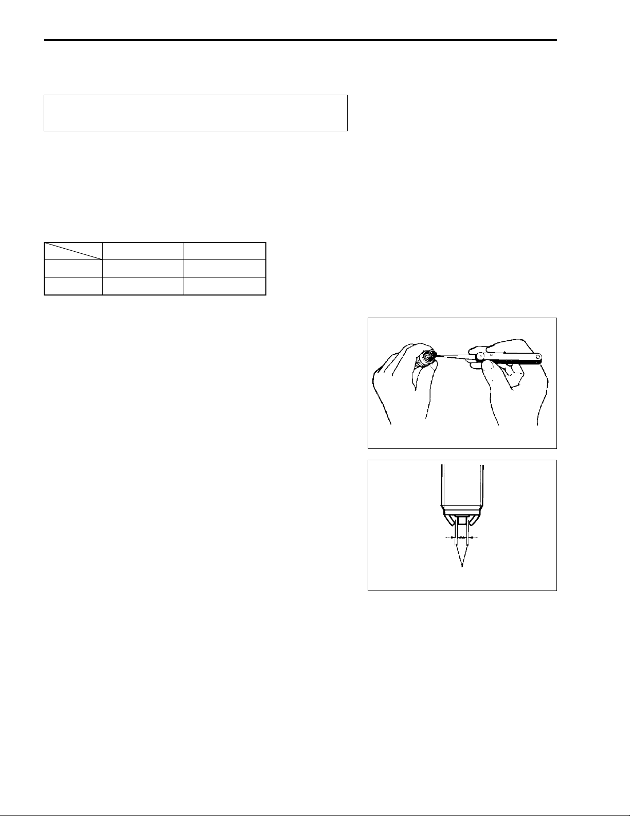
Measure the spark plug gap using a thickness gauge.
If out of specification, regap the spark plug.
" Spark plug gap: 0.6 – 0.7 mm
# 09900-20803: Thickness gauge
ELECTRODE’S CONDITION
Check the condition of the electrode.
If it is extremely worn or burnt, replace the spark plug.
Replace the spark plug if it has a broken insulator, damaged
threads, etc.
$
Check the thread size and reach when replacing the
spark plug. If the reach is too short, carbon will be
deposited on the screw portion of the spark plug hole
and engine damage may result.
SPARK PLUG INSTALLATION
$
To avoid damaging the cylinder head threads, first finger tighten the spark plug and then tighten it to the
proper torque using the spark plug wrench.
PERIODIC MAINTENANCE 2-7
• Insert the spark plugs to the cylinder head by finger tight, and
then tighten them to the specified torque.
& Spark plug: 11 N·m (1.1 kgf-m)
EXHAUST PIPE BOLTS AND
MUFFLER BOLTS
Tighten initially at 1 000 km (1 month) and every
12 000 km (24 months) thereafter.
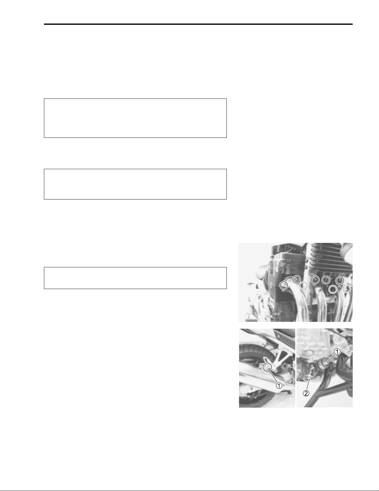
• Tighten the exhaust pipe bolts and muffler bolts to the specified torque.
& Exhaust pipe bolt: 23 N·m (2.3 kgf-m)
& Muffler mounting bolt
Muffler connecting bolt
1: 23 N·m (2.3 kgf-m)
2: 23 N·m (2.3 kgf-m)
2-8 PERIODIC MAINTENANCE
MarMark
Mark
AIR CLEANER
Inspect every 6 000 km (12 months) and replace every
18 000 km (36 months).
• Remove the fuel tank. (!4-3)
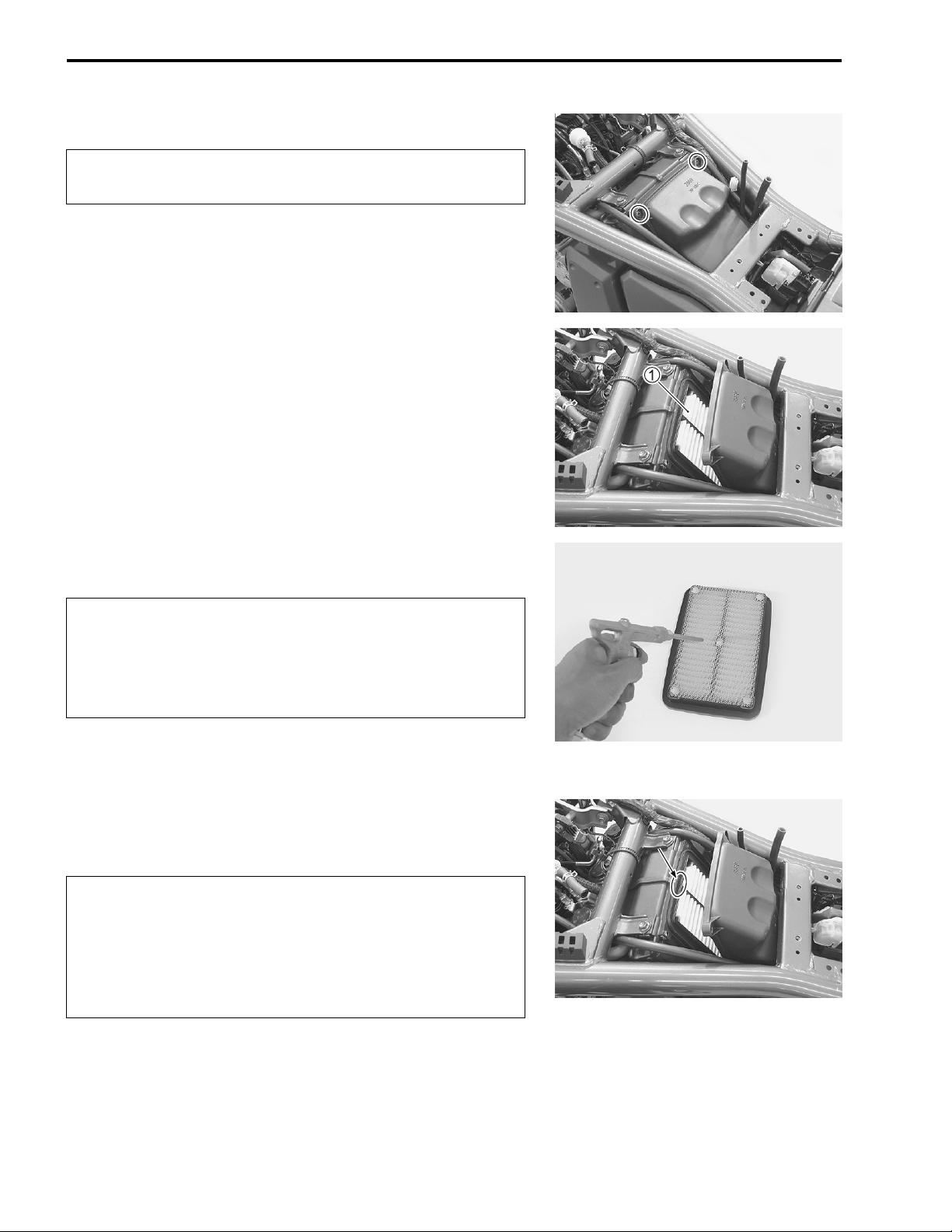
• Remove the screws.
• Remove the air cleaner element
1.
• Carefully use compressed air to clean the air cleaner element.
$
Always apply compressed air to the inside of the air
cleaner element. If compressed air is applied to the
outside, dirt will be forced into the pores of the air
cleaner element, restricting air flow through the air
cleaner element.
• Reinstall the cleaned or new air cleaner element in the
reverse order of removal.
• When installing the air cleaner element into the air cleaner
box, make sure that the mark points up.
$
If driving under dusty conditions, clean the air cleaner
element more frequently. The surest way to accelerate
engine wear is to operate the engine without the element or to use a torn element. Make sure that the air
cleaner is in good condition at all times. Life of the
engine depends largely on this component.
• Remove the drain plug from the air cleaner drain hose to
allow any water to drain out.
ENGINE OIL AND OIL FILTER
(ENGINE OIL)
Replace initially at 1 000 km (2 month) and every 6 000
km (12 months) thereafter.
(OIL FILTER)
Replace initially at 1 000 km (2 month) and every 12 000
km (24 months) thereafter.
PERIODIC MAINTENANCE 2-9
The oil should be changed while the engine is warm. Oil filter
replacement at the above intervals, should be done together
with the engine oil change.
ENGINE OIL REPLACEMENT
• Keep the motorcycle upright.
• Place an oil pan below the engine, and drain engine oil by
removing the oil drain plug
• Tighten the oil drain plug
new oil through the oil filler. When performing an oil change
(without oil filter replacement), the engine will hold about 3.3 L
of oil. Use SF/SG or SH/SJ with JASO MA in API (American
Petroleum Institute) classification.
1 and filler cap
1 to the specified torque, and pour
2.
& Oil drain plug: 23 N·m (2.3 kgf-m)
2-10 PERIODIC MAINTENANCE
• Start up the engine and allow it to run for several minutes at
idling speed.
• Turn off the engine and wait about three minutes, then check
the oil level through the inspection window
below the “L” mark, add oil to the “F” mark. If the level is
above the “F” mark, drain the oil until the level reaches the “F”
mark.
OIL FILTER REPLACEMENT
• Drain engine oil as described in the engine oil replacement
procedure.
• Remove the oil filter
• Apply engine oil lightly to the O-ring of new oil filter, before
installation.
# 09915-40610: Oil filter wrench
1 using the special tool.
3. If the level is
• Install the new oil filter. Turn it by hand until you feel that the
oil filter O-ring has contacted the oil filter mounting surface.
Then, tighten the oil filter two full turns using the special tool.
NOTE:
* Before installing the oil filter, apply a light coat of engine oil
onto its O-ring.
* To properly tighten the oil filter, use the special tool. Never
tighten the oil filter by hand only.
• Add new engine oil and check the oil level as described in the
engine oil replacement procedure.
" NECESSARY AMOUNT OF ENGINE OIL
Oil change: 3.3 L
Oil and filter change: 3.5 L
Engine overhaul: 4.6 L
$
ONLY USE A GENUINE SUZUKI MOTORCYCLE OIL
FILTER.
Other manufacturer’s oil filters may differ in thread
specifications (thread diameter and pitch), filtering
performance and durability which may lead to engine
damage or oil leaks. Also, do not use a genuine Suzuki
automobile oil filter on this motorcycle.
FUEL LINE
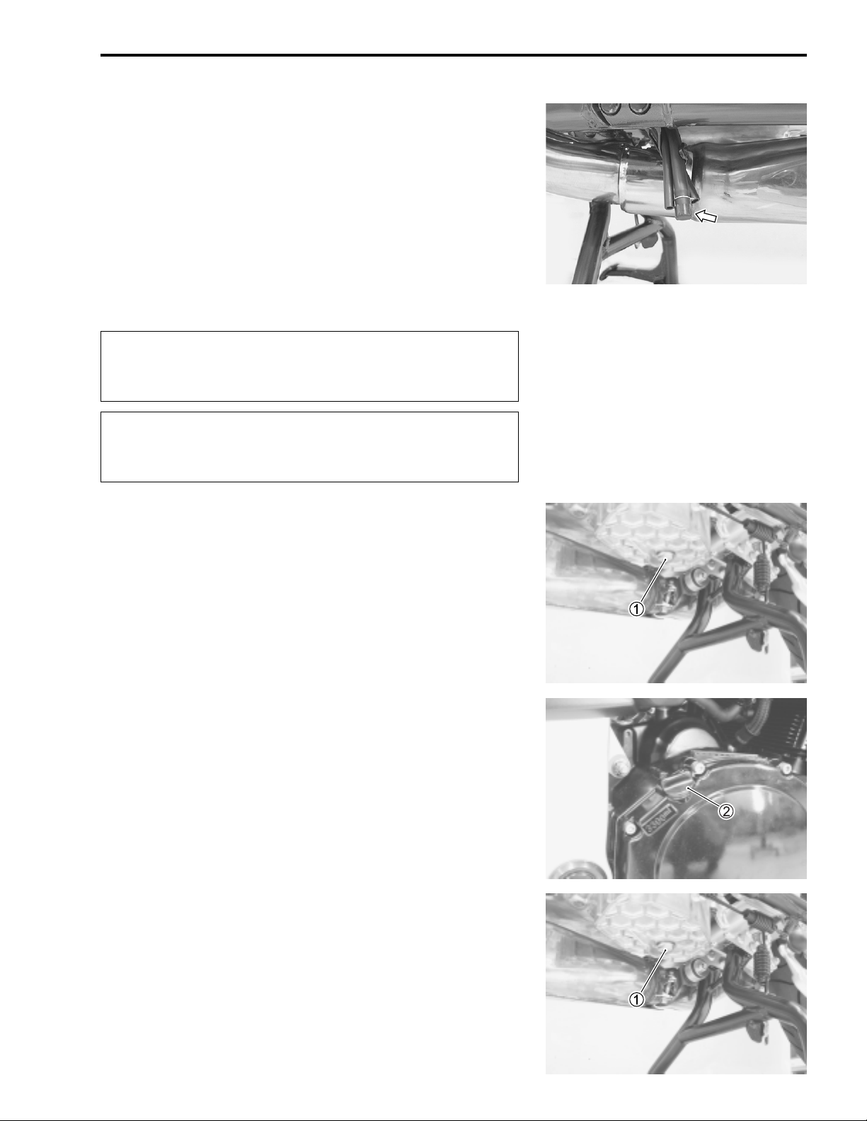
Inspect every 6 000 km (12 months).
• Remove the seat.
• Remove the fuel tank mounting bolts. (!4-3)
• Lift up the fuel tank.
Inspect the fuel hoses
defects are found, the fuel hoses must be replaced.
1 for damage and fuel leakage. If any
ENGINE IDLE SPEED
Inspect initially at 1 000 km (2 month) and every 6 000
km (12 months) thereafter.
NOTE:
Make this adjustment when the engine is hot.
PERIODIC MAINTENANCE 2-11
• Start the engine, turn the throttle stop screw
engine idle speed between 1 100 and 1 300 r/min.
" Engine idle speed: 1 200 ± 100 r/min
1 and set the
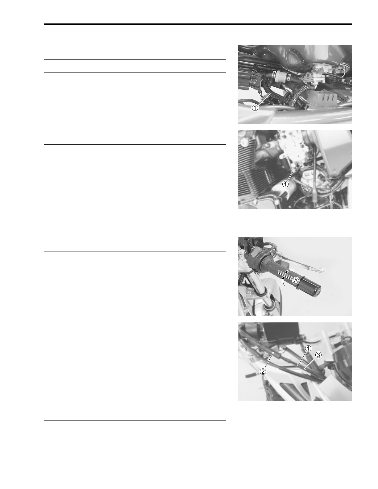
THROTTLE CABLE PLAY
Inspect initially at 1 000 km (2 month) and every 6 000
km (12 months) thereafter.
Adjust the throttle cable play
• Loosen the locknut
• Turn the adjuster
the throttle grip)
• Tighten the locknut
" Throttle cable play
1 of the throttle pulling cable
3 in or out until the throttle cable play (at
A is between 2 – 4 mm.
1 while holding the adjuster
A as follows.
2.
3.
A: 2 – 4 mm
'
After the adjustment is completed, check that handlebar movement does not raise the engine idle speed
and that the throttle grip returns smoothly and automatically.
NOTE:
Major adjustment can be made at the carburetor side adjusters.
(!4-24)
2-12 PERIODIC MAINTENANCE
CARBURETOR SYNCHRONIZATION
Inspect initially at 1 000 km (2 month) and every 12 000
km (24 months).
(!4-25)
PAIR (AIR SUPPLY) SYSTEM
Inspect every 12 000 km (24 months).
(!3-97)
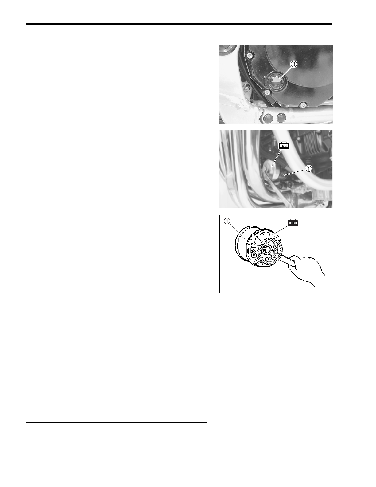
FUEL FILTER
Inspect every 6 000 km (12 months) and replace every
12 000 km (24 months).
• Lift up the fuel tank. (!2-10)
Check the fuel filter
present, replace the fuel filter with a new one. (!4-6)
1 for evidence of dirt and contamination. If
CLUTCH CABLE PLAY
Inspect every 6 000 km (12 months).
• Loosen the locknut
the clutch lever assembly.
• Remove the clutch release cover.
• Loosen the locknut
or three rotations.
• Then, slowly turn in the adjusting screw
felt.
• Then, turn out the adjusting screw
the locknut
• Loosen the locknut
10 – 15 mm of free play
• Tighten the locknut
3.
1 and turn the adjuster
3, and turn out the adjusting screw
4 1/4 of a turn, and tighten
5, and turn the cable adjuster
A at the clutch lever end.
5.
2 all the way into
4 until resistance is
6 to obtain
4 two
" Clutch cable play
A: 10 – 15 mm
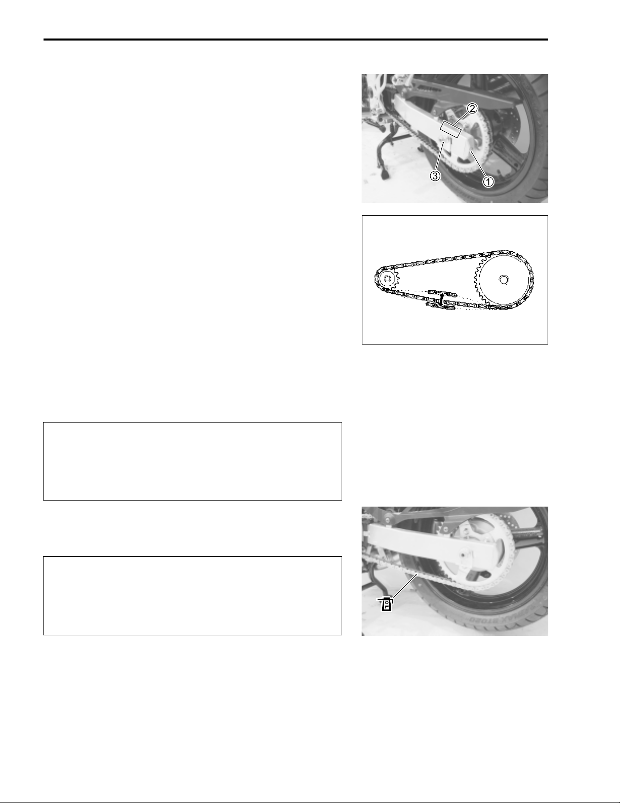
DRIVE CHAIN
Inspect initially at 1 000 km (2 month) and every 6 000
km (12 months) thereafter.
Lubricate every 1 000 km.
With the transmission in neutral, support the motorcycle using
the center-stand and turn the rear wheel slowly by hand. Visually check the drive chain for the possible defects listed below.
* Loose pins * Excessive wear
* Damaged rollers * Improper chain adjustment
* Dry or rusted links * Missing O-ring seals
* Kinked or binding links
A O-ring
B Grease
If any defects are found, the drive chain must be replaced.
NOTE:
When replacing the drive chain, replace the drive chain and
sprockets as a set.
PERIODIC MAINTENANCE 2-13
CHECKING
• Remove the cotter pin. (E-28)
• Loosen the axle nut
1.
• Tense the drive chain fully by turning both chain adjuster bolts
2.
• Count out 21 pins (20 pitches) on the chain and measure the
distance between the two points. If the distance exceeds the
service limit, the chain must be replaced.
" Drive chain 20-pitch length
Service Limit: 319 mm
123 19 20
21
2-14 PERIODIC MAINTENANCE
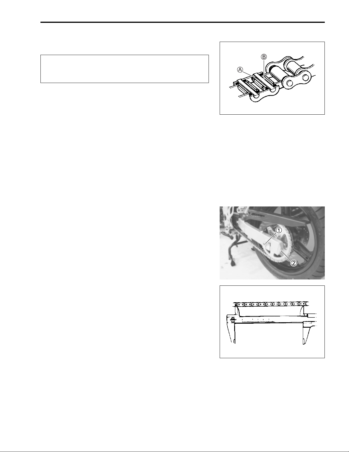
20 – 30 mm
ADJUSTING
• Loosen or tighten both chain adjuster bolts
1 until there is 20
– 30 mm of slack at the middle of the chain between the
engine and rear sprockets as shown. The reference marks
on both sides of the swingarm and the edge of each chain
adjuster must be aligned to ensure that the front and rear
wheels are correctly aligned.
• Place the motorcycle on its side-stand for accurate adjustment.
• After adjusting the drive chain, tighten the axle nut
3 to the
specified torque.
• Tighten both chain adjuster bolts
1 securely.
& Rear axle nut: 100 N·m (10.0 kgf-m)
• Replace the cotter pin with a new one. (E-28)
2
CLEANING AND LUBRICATING
• Clean the drive chain with kerosine. If the drive chain tends to
rust quickly, the intervals must be shortened.
$
Do not use trichloroethylene, gasoline or any similar
solvent.
These fluids have too great a dissolving power for this
chain and they can damage the O-rings. Use only kerosine to clean the drive chain.
• After cleaning and drying the chain, oil it with a heavyweight
motor oil.
$
* Do not use any oil sold commercially as “drive chain
oil”. Such oil can damage the O-rings.
* The standard drive chain is a RKFS50SMOZ1.
SUZUKI recommends to use this standard drive
chain as a replacement.
DRIVE CHAIN CUTTING AND RECONNECTING (!5-70)
BRAKES
(BRAKE)
Inspect initially at 1 000 km (2 month) and every 6 000
km (12 months) thereafter.
(BRAKE HOSE AND BRAKE FLUID)
Inspect every 6 000 km (12 months).
Replace hoses every 4 years. Replace fluid every 2
years.
BRAKE FLUID LEVEL
• Keep the motorcycle upright and place the handlebar straight.
• Check the brake fluid level by observing the lower limit line on
the front and rear brake fluid reservoirs.
• When the brake fluid level is below the lower limit line, replenish with brake fluid that meets the following specification.
PERIODIC MAINTENANCE 2-15
( Specification and classification: DOT 4
'
* The brake system of this motorcycle is filled with a
glycol-based brake fluid. Do not use or mix different
types of fluid such as silicone-based and petroleum-based fluids. Do not use any brake fluid taken
from old, used or unsealed containers. Never re-use
brake fluid left over from the last servicing or stored
for a long period of time.
* Brake fluid, if it leaks, will interfere with safe running
and immediately discolor painted surfaces. Check
the brake hoses and hose joints for cracks and oil
leakage before riding.
2-16 PERIODIC MAINTENANCE
BRAKE PADS
The extent of brake pad wear can be checked by observing the
grooved limit line
grooved limit line, replace the pads with new ones. (!5-47)
$
Replace the brake pads as a set, otherwise braking
performance will be adversely affected.
1 on the pad. When the wear exceeds the
BRAKE PEDAL HEIGHT
• Loosen the locknut
• Turn the push rod
the top of the footrest.
• Tighten the locknut
" Brake pedal height
Standard: 60 mm
& Master cylinder push rod locknut: 18 N·m (1.8 kgf-m)
BRAKE LIGHT SWITCH
Adjust the rear brake light switch so that the brake light will
come on just before pressure is felt when the brake pedal is
depressed.
1.
2 until the brake pedal is 60 mm
1 securely.
A
A below
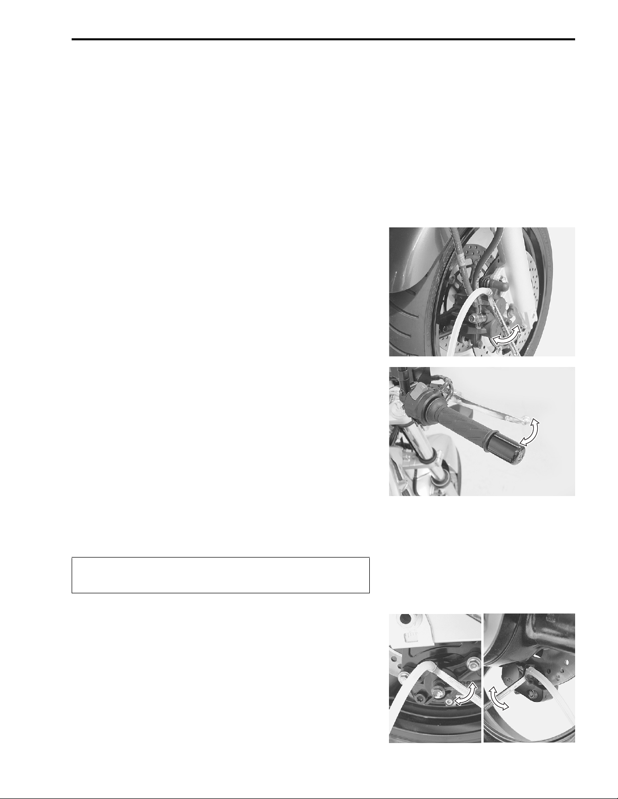
AIR BLEEDING THE BRAKE FLUID CIRCUIT
Air trapped in the brake fluid circuit acts like a cushion to absorb
a large proportion of the pressure developed by the master cylinder and thus interferes with the full braking performance of the
brake caliper. The presence of air is indicated by “sponginess”
of the brake lever and also by lack of braking force. Considering
the danger to which such trapped air exposes the machine and
rider, it is essential that, after remounting the brake and restoring the brake system to the normal condition, the brake fluid circuit be purged of air in the following manner:
Front brake
• Fill the master cylinder reservoir to the top of the inspection
window. Place the reservoir cap to prevent dirt from entering.
• Attach a hose to the air bleeder valve, and insert the free end
of the hose into a receptacle.
• Squeeze and release the brake lever several times in rapid
succession and squeeze the lever fully without releasing it.
Loosen the air bleeder valve by turning it a quarter of a turn so
that the brake fluid runs into the receptacle, this will remove
the tension of the brake lever causing it to touch the handlebar grip. Then, close the air bleeder valve, pump and squeeze
the lever, and open the valve. Repeat this process until the
fluid flowing into the receptacle no longer contains air bubbles.
PERIODIC MAINTENANCE 2-17
NOTE:
While bleeding the brake system, replenish the brake fluid in the
reservoir as necessary. Make sure that there is always some
fluid visible in the reservoir.
• Close the air bleeder valve, and disconnect the hose. Fill the
reservoir with brake fluid to the top of the inspection window.
& Air bleeder valve: 8 N·m (0.8 kgf-m)
$
Handle brake fluid with care: the fluid reacts chemically with paint, plastics, rubber materials, etc.
Rear brake
NOTE:
Rear brake caliper has two bleeder valves.
 Loading...