


OWNER’S MANUAL
INSTALLATION • OPERATION • MAINTENANCE
SAFETY PRECAUTIONS • REPAIR PARTS
X9
12 & 24 Volt DC Electric Winch
Models 1901, 1902
READ AND UNDERSTAND THIS MANUAL BEFORE INSTALLATION
AND OPERATION OF YOUR SUPERWINCH PRODUCT.
90-17371 Rev - 5/10/04
Superwinch, Inc. Superwinch, Ltd.
Winch Drive Abbey Rise, Whitchurch Road
Putnam, CT 06260 Tavistock, Devon PL 19 9DR
U.S.A. England
Tel. (860) 928-7787 Tel. +44 (0) 1822 614101
Fax (860) 963-0811 Fax +44 (0) 1822 615204
VALABLE A TRAVERS LE MONDE
GARANTIE LIMITÉE. Superwinch, Inc. (le “Vendeur”) garantit à l’acheteur d’origine (“vous”) que
toutes les pièces et composants, à l’exception du câble métallique, sont sans vice de matériaux ou
de fabrication, et ce, pendant une période d’un (1) an à compter de la date d’achat prouvable.
Tout produit Superwinch défectueux sera réparé ou remplacé sans dépenses de votre part si vous
respectez ces procédures. Les garanties énoncées par les présentes sont exclusives tiennent lieu de
toutes autres garanties expresses ou implicites.
PROCÉDURE DE RECOURS À LA GARANTIE LIMITEE.
Dès découverte d’un produit Superwinch défectueux, vous devrez envoyer à Superwinch, à l’usine
ou à un Centre de réparation autorisé par l’usine, une notification écrite dudit défaut et vous
devrez envoyer par courrier ou autre service de livraison le Superwinch défectueux, port et frais
postaux payés à l’avance. Les réparations ou remplacements par le Vendeur conformément à la
présente Garantie s’effectueront normalement dans les quinze (15) jours ouvrables suivant réception du Superwinch défectueux. Le Vendeur ou ses Agents autorisés peut facturer des frais
raisonnables pour les pièces et la main d’oeuvre en cas de réparation non couverte par la présente
Garantie limitée.
LIMITATIONS ET EXCLUSIONS EN CE QUI CONCERNE LA GARANTIE ET LES REMÈDES.
La réparation et/ou le remplacement de tout Superwinch défectueux ou de tout composant d’un
tel Superwinch tel que convenu par les présentes est votre remède exclusif. Les exclusions et limitations de garanties et les limitations de REMEDES ci-dessous seront expressément applicables :
A. Garanties expresses . Le Vendeur garantit que le Superwinch est tel qu’il est décrit dans le
“Mode d’emploi Superwinch” fourni avec la présente; aucune autre garantie expresse n’est donnée en ce qui concerne le Superwinch. Si un modèle ou échantillon vous a été montRé, ledit modèle ou échantillon a été utilisé à des fins d’illustration uniquement et ne sera pas considéré une
garantie que le Superwinch sera conforme au modèle ou à l’échantillon. LE VENDEUR NE DONNE
AUCUNE GARANTIE EXPRESSE EN CE QUI CONCERNE LE CABLE MÉTALLIQUE INCORPORÉ AU PRODUIT.
B. Garantie implicite . LA GARANTIE IMPLICITE DE L’APTITUDE À LA VENTE ET TOUTE AUTRE
GARANTIE IMPLICITE S’APPLIQUERA UNIQUEMENT POUR UNE DURÉE D’UN (1) AN À COMPTER DE
LA DATE D’ACHAT PROUVABLE. LE CABLE MÉTALLIQUE EST VENDU “TEL QUEL” SANS AUTRE
GARANTIE IMPLICITE. CERTAINS ÉTATS AMÉRICAINS NE PERMETTENT PAS DE LIMITER LA DURÉE
DES GARANTIES IMPLICITES; IL EST DONC POSSIBLE QUE LA LIMITATION CI-DESSUS NE S’APPLIQUE
PAS À VOTRE CAS.
C. Dommages indirects. SUJET AUX OBLIGATIONS DE LA GARANTIE LIMITÉE DU VENDEUR
ÉNONCÉES DANS LE PRÉSENT DOCUMENT, LE VENDEUR NE SERA AUCUNEMENT RESPONSABLE DE
DOMMAGES INDIRECTS, DE QUELQUE NATURE QUE CE SOIT, NI DE DOMMAGES INDIRECTS À LA
PROPRIÉTÉ, NI DE PERTES DE PROFITS, NI DE PERTES D’UTILISATION POUVANT SURVENIR À CAUSE
D’UN DÉFAUT, D’UN MAUVAIS FONCTIONNEMENT OU D’UNE PANNE QUELCONQUE DU SUPERWINCH CI-JOINT. CERTAINS ÉTATS AMÉRICAINS NE PERMETTENT PAS D’EXCLURE OU DE LIMITER
LES DOMMAGES INDIRECTS; IL EST DONC POSSIBLE QUE LA LIMITATION CI-DESSUS NE S’APPLIQUE
PAS À VOTRE CAS.
D. Condition de la garantie. Le Vendeur ne sera pas tenu de se conformer aux obligations de
garantie fournies par les présentes si la cause du défaut, du mauvais fonctionnement ou de la
panne du Superwinch est un dommage (ne résultant pas de composants défectueux ou qui fonctionnent mal) ou une utilisation déraisonnable par vous. Le terme Utilisation déraisonnable comprend mais ne est pas limité au manquement à la maintenance, à l’installation et à l’utilisation
raisonnables et nécessaires conformément aux consignes contenues dans le Mode d’emploi
Superwinch, et à l’utilisation du Superwinch pour des charges supérieures à celle figurant dans le
Mode d’emploi pour le modèle en question. La responsabilité du Vendeur sous la présente
garantie ou pour toute perte du produit Superwinch ou dommage à celui-ci ne dépassera pas le
coût de correction des défauts du produit Superwinch ou de remplacement de celui-ci, et lors de
l’expiration de la période de garantie, toute telle responsabilité prendra fin. Les agents, distributeurs et employés du Vendeur ne sont pas autorisés à modifier la présente garantie ni à donner
d’autres garanties complémentaires obligatoires pour le Vendeur. Toute déclaration supplémen-
taire, qu’elle soit écrite ou orale, ne constituera donc pas une garantie et ne devra pas être considérée comme valable.
REMEDES LÉGAUX DE L’ACHETEUR. Cette garantie limitée vous donne des droits légaux spéci-
fiques et il est possible que vous ayez d’autres droits qui varient d’un état à l’autre aux Etats-Unis
et d’un pays à l’autre. Vous avez également des droits de garantie implicite. En cas de problème
avec le service ou la performance suivant la garantie limitée, il est possible que vous puissiez intenter une action en justice devant la Cour des Prudhommes (“small claims court”), devant le tribunal
d’état ou devant le tribunal fédéral des Etats-Unis ou dans une autre juridiction appropriée en
dehors des Etats-Unis.
QUESTIONS. Toute question en ce qui concerne le respect des garanties énoncées dans les
présentes doit être envoyée, par écrit, à : Superwinch, Inc., Winch Drive, Putnam, CT 08260 U.S.A.
ou à Superwinch Limited, Abbey Rise, Whitchurch Road, Tavistock, Devon PL 19 9DR, England
GARANTIE LIMITÉ E
CAUTION
!
2
Thank you for purchasing an X9 winch from Superwinch. It has been designed and manufactured to provide years of trouble-free operation. We hope you will be pleased with its performance. If you are not, for any reason, please contact our Customer Service Department:
(860) 928-7787 USA; +44 (0) 1822 614101 England.
When requesting information or ordering replacement parts; always give the
following information:
1. Winch Part Number (1901, 1902)
2. Serial Number (found on motor adapter casting)
3. Part Number (found in Replacement Parts List section)
4. Part Description
Please read and understand this Owner’s Manual prior to installing and using your winch.
Pay particular attention to the General Safety Information. Your winch is a very powerful
machine. If used unsafely or improperly, there is a possibility that property damage or personal injury can result. We have included several features in this winch to minimize this possibility; however, your safety ultimately depends on your caution when using this product.
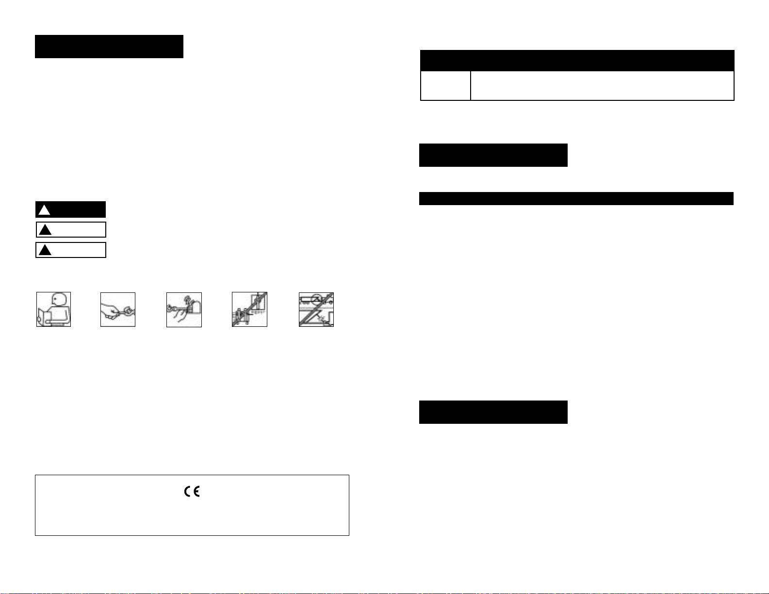
Throughout this manual, you will find notations with the following headings:
Indicates an imminently hazardous situation which, if not avoided,
will result in death or serious injury.
Indicates a potentially hazardous situation which, if not avoided,
could result in death or serious injury.
Indicates a potentially hazardous situation which, if not avoided,
may result in minor or moderate injury. This notation is also used
to alert against unsafe practices.
The following symbols on the product and in the Owner's manual are used:
Note:
Indicates additional information in the installation and operation procedures
of your winch.
Correct installation of your X9 winch is a requirement for proper operation. If you install
your X9 winch on the front end of your vehicle,
use the X9 mounting (fitting) kit which
has been designed and manufactured by Superwinch to accommodate your winch and fit
your vehicle.
Please Note: The Superwinch model X9 winch is designed primarily for front mount vehicle
use and for other intermittent applications. This winch is not designed to be used in hoisting
applications and Superwinch does not warrant it to be suitable for such use. Please contact
our Customer Service Department for further information. Note the electrical requirements
of the X9 winch you have purchased:
Part No. 1901 12-volt DC system Only
Part No. 1902 24-volt DC system Only
Congratulations on your choice!
Description Quantity
Winch assembly with wire rope 1
Solenoid assembly 1
Solenoid mounting bracket 1
1/4-20 Hex head bolts 4
1/4-20 Hex nuts 2
1/4 External tooth lock washer 4
Terminal boots 3
3/8-16 Square nuts 4
3/8 Lock washers 4
3/8-16 x 1 Hex head bolts, grade 8 4
Hand saver 1
7" Wire ties 6
Long lead wire assembly (color coded black) 1
Remote pendant 1
Clevis hook 1
Owner’s manual 1
INTRODUCTION
Electric Motor – 4.2 peak hp (3.1 kw)
12V Series Wound or 3.5 peak hp (2.6
kw) 24V Series Wound.
Braking – A one way drag brake will
hold a 4,500 lb. (2041 kg) load on the
first wrap.
Drum – Fabricated steel running
in copolymer maintenance free
bearings.
Freespool Clutch – Operated by an
easy action lever which disengages
the gearbox to allow the wire rope
to be pulled out without using electric
power. A spring-loaded drag mechanism
reduces backlash and snarling when
pulling out the wire rope.
Remote Switch – 15' (4.5m) hand
held pendant switch assembly.
Mounting – Optional custom-engi-
neered mounting kits are available
for vehicle frame attachment.
FEATURES
This carton contains the following items. Please unpack carefully.
Read instructions before beginning.
UNPACKING
3
European Union
Noise The noise level for this winch in operation is below 92 dB(A).
Wire Rope Winches that conform to Machinery Directive 89/392/EEC, are fitted with a 3/8" x 75 ft. wire rope
(p/n 90-20136-03), in lieu of standard 5/16" x 100 ft. wire rope.
Emergency Stop In order to conform to Machinery Directive 89/392/EEC, each machine installation must be
fitted with an Isolator switch (p/n 1562) whereby the machine can be brought safely to a complete stop.
Read Owner's
Manual
Always Use
Handsaver
Keep clear of winch,
wire rope and hook
while operating
Never use winch
to lift or move
people
Never use
winch to hold
loads in place
Grade** 10% (6º) 20% (11º) 30% (17º) 60% (31º) 100% (45º)
Lbs.
kg
45,225
20514
30,600
13880
23,500
10659
15,000
6804
11,575
5250
* Ratings assume a 10% coefficient of friction.
** A 10% grade is a rise of one foot in ten feeet. Slope in approximate degrees is also shown.
ROLLING LOAD CAPACITIES*
Superwinch is not responsible for printing errors inadvertently made in the production of this manual.
DANGER
!
WARNING
!
CAUTION
!
5
PERFORMANCE
Your X9 winch is a very powerful
machine. Treat it with respect, use it
with caution and always follow these
safety guidelines.
The responsibility
for safe installation and operation of the winch and
prevention of personal injury and
property damage ultimately rests
with you, the operator. There is
no substitute for the use of good
judgement and caution in operating
a winch.
The wire rope
may break before
the winch stalls. For heavy loads, use
a pulley block to reduce the load on
the wire rope.
1. The X9 winch is rated at 9,000
pounds (4082 kg) (single line)
capacity on the wire rope layer
closest to the drum. DO NOT
OVERLOAD. DO NOT ATTEMPT
PROLONGED PULLS AT HEAVY
LOADS. Do not maintain power
to the winch if the motor stalls.
Overloads can damage the winch
and/or the wire rope and create
unsafe operating conditions. FOR
LOADS OVER 6,000 POUNDS (2721
KG), WE RECOMMEND THE USE OF
THE OPTIONAL PULLEY BLOCK TO
DOUBLE LINE THE WIRE ROPE
(Figures 1 & 14). This reduces the
load on the winch and the strain
on the wire rope by approximately
50%. If attaching back to vehicle,
attach to the frame or other load
bearing part.
The vehicle engine
should be running during winch
operation to minimize battery
drain and maximize winch
power and speed.
If considerable
winching is performed with the
engine off, the battery may be
too weak to restart the engine.
2. AFTER READING AND UNDERSTANDING THIS MANUAL, LEARN
TO USE YOUR WINCH. After
installing the winch, practice
using it so you will
be familiar
with it when the
need arises.
3.
DO NOT “move” your vehicle to
assist the winch in pulling a load.
The combination of the winch and
vehicle pulling together could overload the wire rope and the winch
itself.
4. KEEP WINCHING AREA CLEAR. Do
not allow people to remain in the
area during winching operations.
ALWAYS STAND CLEAR OF WIRE
ROPE/HOOK AND WINCH. IN THE
UNLIKELY EVENT OF ANY COMPONENT FAILURE IT‘S BEST TO BE OUT
OF HARM‘S WAY.
5. INSPECT WIRE ROPE AND EQUIPMENT FREQUENTLY.
A FRAYED
WIRE ROPE WITH BROKEN
STRANDS SHOULD BE REPLACED
IMMEDIATELY.
Always replace
wire rope with the manufacturer‘s
identical replacement part (see
Replacement Parts List). Periodically
check the winch installation to
ensure that all bolts are tight.
6. USE HEAVY LEATHER GLOVES when
handling wire rope. DO NOT LET
WIRE ROPE SLIDE THROUGH YOUR
HANDS EVEN WHEN WEARING
GLOVES.
GENERAL SAFETY
INFORMATION
Wire Rope Max. Pulling Capacity
Layer lbs kg
1 9,000 4082
2 7,365 3340
3 6,230 2825
4 5,400 2450
5 4,765 2161
INTERMITTENT DUTY
Working Load* . . . 9,000 lbs. (4082 kg)
Stall Load 12V*, 24V* . . . . .12,700 lbs.
(5760 kg)
Wire Rope . . . . . . . . . . 5/16" x 100'
12V Motor . . . 4.2 hp (3.1 kw) peak
24V Motor . . . 3.5 hp (2.6 kw) peak
Gear Ratio . . . . . . . . . . . . . . . 253:1
*Based on first layer performance
SPECIFICATIONS
4
An electric winch is like any other
motor driven power tool such as an
electric drill or saw. The electric
motor should not be allowed to
become excessively hot. Normal precautions will extend the life of your
motor. Keep the duration of pulls as
short as possible.
If the end of the
motor becomes uncomfortably
hot to touch, stop winching and
allow the motor to cool down.
If the winch
motor stalls,
do not continue to apply power
to the winch.
Figure 1
Single Line
Double Line
Speed* Speed* Motor
Load 12V 24V Current (Amps)*
lbs kg ft/min m/min ft/min m/min 12V 24V
0 0 38.2 11.6 38.0 11.6 73 42
1,000 454 18.0 5.5 21.7 6.6 130 72
2,000 907 13.8 4.2 17.1 5.2 165 90
4,000 1814 9.0 2.7 12.0 3.6 240 133
6,000 2722 6.0 1.8 8.3 2.5 316 181
9,000 4082 2.5 0.8 3.5 1.0 420 252
CAUTION
!
WARNING
!
WARNING
!
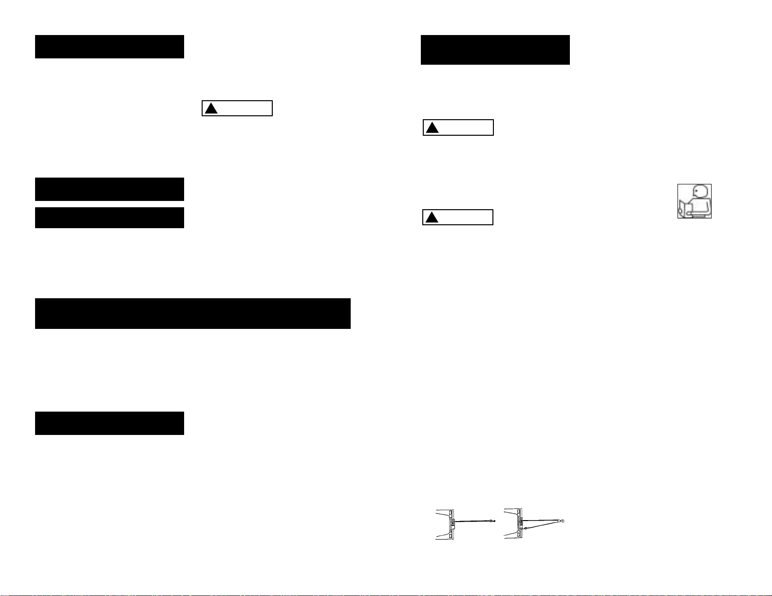
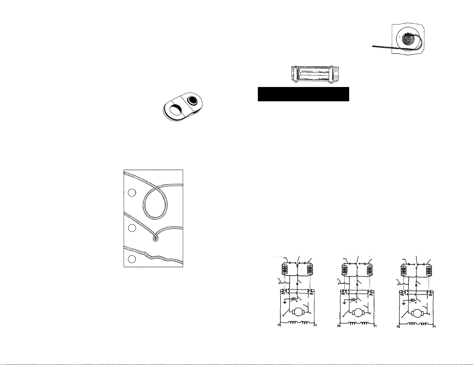
7. NEVER WINCH WITH LESS THAN 5
TURNS of wire rope AROUND THE
WINCH DRUM since the wire rope
end fastener will NOT withstand
a load. Your X9 winch wire rope
has a ten-foot red “warning indicator” on each end. The “warning indicator” at the winch end
warns you that the wire rope is
near or less than 5 turns. The
“warning indicator” at the hook
end of the wire rope warns you
that the hook is approaching the
winch. ALWAYS USE THE HANDSAVER when guiding the wire
rope in or out (see Figure 2). As
you use your winch, the red paint
will wear off due to normal use.
When this happens, renew the
red paint as it is
a
safety feature of
the winch.
8. KEEP CLEAR OF WINCH, TAUT
WIRE ROPE AND HOOK WHEN
OPERATING WINCH. Never put
your finger through the hook. If
your finger should become
trapped in the hook, you could
be injured.
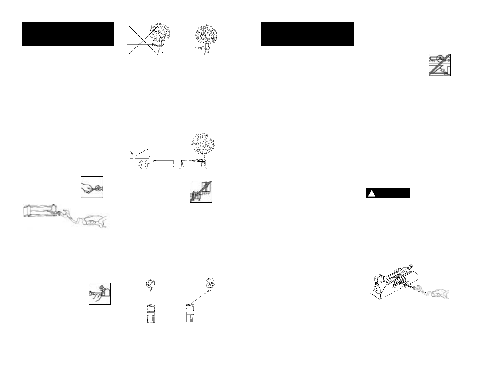
Never
guide a wire rope
onto the drum with
your hand.
9. NEVER HOOK THE WIRE ROPE
BACK ONTO ITSELF. You could
damage the wire rope. Use a
nylon sling (Figure 3).
10. Lay a heavy blanket or jacket
over the wire rope near the
hook end when pulling heavy
loads (Figure 4). Should a wire
rope failure occur, the cloth will
act as a damper and help prevent the rope from whipping.
Raise the hood of the vehicle
for added protection.
11. NEVER USE YOUR
WINCH FOR LIFTING
PEOPLE OR MOVING
PEOPLE.
12. Your winch is not intended for
overhead hoisting operations.
13. AVOID CONTINUOUS PULLS
FROM EXTREME ANGLES as this
will cause the wire rope to pile
up at one end of the drum
(Figure 5). This can jam the wire
rope in the winch, causing damage
to the wire rope or winch itself.
14. NEVER OBSCURE THE WARNING
INSTRUCTION LABELS.
15. Always operate winch with an
unobstructed view of the winching operation.
16. Equipment such as tackle, hooks,
pulley blocks, straps, etc. should
be sized to the winching task
and should be periodically
inspected for damage that could
reduce their strength.
17. NEVER RELEASE FREESPOOL
CLUTCH WHEN THERE IS A LOAD
ON THE WINCH.
18. STORE THE REMOTE PENDANT
ASSEMBLY IN A SAFE PLACE
when not in use to prevent use
by children or other unauthorized persons who could injure
themselves or others.
19. DO NOT OPERATE WINCH
WHEN UNDER THE INFLUENCE
OF DRUGS, ALCOHOL OR
MEDICATION.
20. ALWAYS UNPLUG THE REMOTE
PENDANT BEFORE WORKING IN
OR AROUND THE FAIRLEAD OR
WINCH DRUM (THE DANGER
ZONE) so that the winch cannot
be turned on accidentally.
21. When moving a load, slowly
take up the wire rope slack until
it becomes taut. Stop, recheck
all winching connections. Be
sure the hook is properly seated.
If a nylon sling is used, check the
attachment to the load.
22. When using your winch to move
a load, place the vehicle transmission in neutral, set vehicle
parking brake, and chock all
wheels.
23. DO NOT USE THE WINCH TO
HOLD LOADS IN PLACE. Use
other means of securing loads
such as tie down straps.
Superwinch offers a
wide variety of tie
downs. Contact your
local Superwinch
dealer.
24. USE ONLY FACTORY APPROVED
SWITCHES, REMOTE CONTROLS
AND ACCESSORIES. Use of nonfactory approved components
may cause injury or property
damage and could void your
warranty.
25. DO NOT MACHINE OR WELD
ANY PART OF THE WINCH. Such
alterations may weaken the
structural integrity of the winch
and will void your warranty.
26. To avoid overheating the motor,
do not power the winch out
longer than 2 minutes.
The drum and
wire rope will
get very hot (Figure 6).
27. DO NOT CONNECT WINCH TO
EITHER 110 VOLT AC HOUSE
CURRENT OR 220V MAINS AS
WINCH BURNOUT OR FATAL
SHOCK MAY OCCUR.
28. Never allow shock loads to be
applied to winch or wire rope.
6
7
Figure 2
GENERAL SAFETY
INFORMATION
(CONT.)
Wrong Right
GENERAL SAFETY
INFORMATION
(CONT.)
Right
Wrong
Figure 5
Figure 3
Figure 4
Figure 6
HOT
HOT
DANGER
!
9
29. Always operate your winch in an
underwound orientation only.
MOUNTING YOUR WINCH
Superwinch mounting (fitting) kits are
available for most popular vehicles. If
you can‘t locate a kit locally, contact
Superwinch at the address listed on
the front of this manual for the name
of a Superwinch dealer near you.
Detailed mounting instructions are
provided with each mounting kit.
Read and install carefully to ensure
proper winch alignment and troublefree operation.
If a Superwinch mounting plate is not
used, refer to Figure 7 for a guide to
construct a mounting system.
Note: The winch can be mounted
foot down or foot forward. See page
11 for details. The preferred mounting position is feet forward. This
winch MUST be mounted with the
wire rope in the underwind direction.
Improper
mounting could
damage your winch, void the
warranty, and cause personal
injury.
MINIMUM ELECTRICAL
REQUIREMENTS
For 12 Volt winches, a 60 amp alternator and battery with 440 coldcranking amperes capacity are the
minimum recommended power
sources. If the winch is in heavy use,
an auxiliary battery and heavy duty
alternator with battery isolator are
recommended.
TOOLS REQUIRED
Open End Wrenches (Spanners):
*(2) 3/8", *(2) 1/2", *(2) 7/16",
*(2) 9/16"
(1) 1/4 inch Hex socket wrench or
straight blade screwdriver
*Adjustable (Crescent) Wrenches may be substituted.
1. Install mounting kit or structural
support for winch.
2. Change the foot orientation (if
required) see page 11.
3. Attach the long black color coded
wire and the ground wire from
solenoid pack to the motor case.
Mount the winch to the mounting kit base plate or to the
mount that you designed (see
Figure 7).
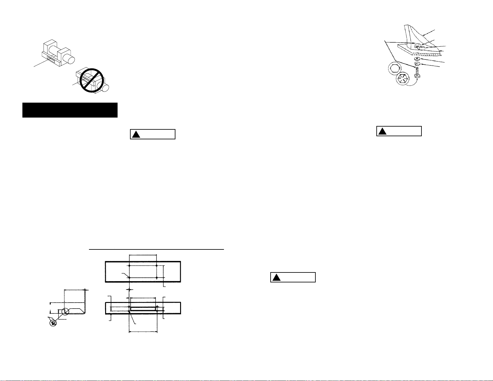
The 3/8-16 mounting bolts supplied are the correct length for
use with a 1/4" thick Superwinch
mounting plate.
The end of the
mounting bolts
must not contact the opposite side
of the support casting’s mounting
pocket (see Figure 8).
Such contact could lead to a damaged
casting, catastrophic failure of the
winch and void the warranty. Adjust
bolt length accordingly if a thicker
plate is used. The bolt threads must
engage all the nut threads.
Always place the square nuts (provided) in the casting pockets when
mounting your winch.
Do not sub-
stitute any
strength grade weaker than SAE
Grade 8 (ISO 10.9). Grade marking
is found on the bolt head and is
pictured in Figure 8.
4. Mount the solenoid pack to the
solenoid pack bracket with the
1/4-20 bolts provided (see Figure
22). Do not mount the bracket to
the mounting plate at this time.
5. Recheck all wire connections that
you just made to be sure they are
correct. If you are using a
Superwinch mounting plate, bolt
the solenoid bracket to the
mount plate with the bolts, external tooth lock washers, and nuts
provided.
Note: If a Superwinch
mounting plate is not used, the
solenoid pack must be mounted
in a way that will provide an electrical ground path from the solenoid case to the battery negative
terminal. Without this ground
path the winch will not work.
If you choose to relocate the solenoid pack or the winch at a
greater distance than wires provided will permit, it may be necessary to purchase a larger gauge
INSTALLATION
8
Support Casting
Mounting Pocket
Square Nut
Flat Washer
Lock Washer
(Must not
touch)
Grade 8 Bolt
Mounting
Plate
10.9
Figure 8
Figure 7
NOTES:
1. All dimensions are in inches
(millimeters).
2. Winch is mounted with 3/8-16
(M 10) hardware. Using 1/4
inch (6.4) thick steel baseplate,
bolt length to be 1 inch (25.4).
Bolts to be SAE Grade 8
(ISO 10.9) or stronger.
3. Use only square nuts in casting
for mounting. (See Figure 8.)
MOUNTING DIMENSIONS
10 (254.0)
4 1/2
(114.3)
1 13/32 (35.7)
13/32 (10.3)
Dia. Holes
(4) Places
Alternate Construction of
Structural Reinforcement
Weld
4 1/8 (104.8)
7 1/2 (190.5)
1/4 (6.4)
1 3/8 (34.9)
1/2 (12.7)
Max. Rad.
1 9/16 (39.7)
5/32 (4.0)
19/32
(15.1)
7/8
(22.2)
13/32 (10.3) Dia.
10 5/16 (261.9)
3/16 (4.8)
Opening
1 3/16 (30.2)
9 (228.6) Opening
Underwind
Overwind
Fig. 2
WARNING
!
CAUTION
!
WARNING
!

wire to get the best performance
from the winch. If the total
length added exceeds 10 ft. (3m),
use a larger wire gauge size.
6. Disconnect the vehicle battery
leads.
Automobile bat-
teries contain
gasses which are flammable and
explosive. Wear eye protection
during installation and remove
all metal jewelry. Do not lean over
battery while making connections.
7. Route the long red and long black
color coded wires to the battery. To
ensure against insulation abrasion
and/or cutting, apply several layers
of electrical tape where wiring may
come in contact with sharp parts on
the vehicle. Attach the red color
coded wire to the battery positive
terminal, and reattach the terminal
to the battery.
If your vehicle is equipped with side
pole terminals, it may be necessary
to obtain auxiliary side terminal
bolts from your local auto parts
dealer to make these connections.
Connect the long black color coded
wire to the battery negative terminal, then connect the terminal to
the battery.
8. Turn the freespool clutch lever to
the “free” position. Pull several
feet of wire rope off the drum.
Return the clutch lever back to
the “Engage” position. Plug in
remote pendant control. Slide the
lever to “Rope Out” position to
check the wire rope drum rotation direction. If drum rotates
in the wrong direction, recheck
your wiring.
To prevent
unauthorized
use of the winch, remove pendant
control and store in a clean dry area
such as the glove box.
Under some circumstances it may
|be appropriate to install additional
circuit protection devices (circuit
breakers). If in doubt, seek appropriate expert advice. Superwinch
recommends that all winch electrical systems can be readily and
quickly isolated from their electrical
supply in the event of an emergency. The winch electrical system
should always be isolated when
the winch is not in use.
PENDANT OPERATION
The handheld pendant switch
activates a solenoid that activates
power to the winch motor.
To connect the pendant control,
remove the cover on the plug receptacle and insert the plug end of
remote switch. The plug on the pendant control cord is keyed and will
fit into the socket only one way.
The switch trigger returns to the
“Off” position when released.
To change direction, move the
toggle in the other direction.
The switch
assembly must
be kept free of dirt and moisture
to ensure safe operation.
10 11
PULLING OUT THE WIRE ROPE
The wire rope has been installed on
your winch under minimal load at
the factory. The wire rope must be
respooled onto the drum under
load so that the outer layers will
not draw down into the inner ones
thereby damaging the wire rope.
Rotate the clutch lever to the “Free
position as shown in Figure 11. If
there is a load on the wire rope,
the clutch lever may not turn easily.
DO NOT FORCE THE CLUTCH LEVER.
Release tension on the wire rope by
jogging out some of the wire rope,
then try releasing the clutch. Pull
out the wire rope and secure to
anchor or load. Check that there
are at least five (5) turns of wire
rope left on the drum. Re-engage
the drum by rotating the clutch
lever to the “Engaged” position
(see Figure 11).
Lever must be in
the engaged posi-
tion and locked before winching.
INSTRUCTIONS FOR CHANGING
WINCH CONFIGURATION
The X9 winch may be used in either
the foot down or foot forward configuration. For convenience of oper-
ation, the Gearbox Housing can be
rotated to position the Clutch Lever
to the top of the winch.
To reposition, remove the (4) screws
holding the Gearbox Housing to the
Gearbox Support Housing. Rotate
the Gearbox Housing to the position that you would like the Clutch
Lever. Replace all (4) screws.
Be careful
to keep the
Gearbox Housing against the
Gearbox Support Housing during
the time the (4) screws are loose
or removed. This will prevent parts
inside the Gearbox Housing from
becoming disengaged.
Be Prepared
Figure 9
Gearbox Screws
Gearbox Support
Housing
Gearbox Housing
Foot Down Configuration
Figure 11
Gearbox Screws
Gearbox Support
Housing
Gearbox Housing
Foot Forward Configuration
Figure 10
Rope In
Rope Out
Figure 12
Figure 13
DANGER
!
CAUTION
!
CAUTION
!
CAUTION
!
CAUTION
!
6. EQUIPPING THE WINCH WITH A
ROLLER FAIRLEAD will substantially
reduce wear on the wire rope
during angle pulls (Figure 16).
The rollers eliminate heavy rubbing and abrasion to the wire rope.
Periodically check tightness of
mounting bolts and electrical connections. Remove any dirt or corrosion that may have accumulated on
the electrical connections.
Repairs should be done by
Authorized Superwinch Repair
Centers ONLY. Do not attempt
to disassemble the gearbox.
Disassembly will void warranty.
LUBRICATION
The gearbox and drum bearing are
permanently lubricated with a high
performance gear lube. If relubrication is necessary (after repair or
disassembly) only use factory
approved grease (Superwinch
Part No. 90-15020).
REPLACING THE WIRE ROPE
Never substitute a heavier or lighter
wire rope. Never use rope made of
any other material other than wire.
Always replace damaged wire
rope with manufacturer’s identi-
cal replacement part
(see
Replacement Parts list). Pass attaching end of wire rope through the
fairlead (if equipped) and attach it
to the drum. When inserting the
wire rope into the drum, insert it
into the correct end of the hole
provided (Figure 17). Tighten the
set screw securely.
It is important that the wire rope
be wound tightly onto the drum. A
good way to do this is to attach the
wire rope hook to a fixed object at
the top of a slight incline, then
winch the vehicle up the incline.
12
13
TIPS FOR EXTENDING THE LIFE OF
THE WINCH
1. KEEP A TIGHTLY WOUND WIRE
ROPE DRUM. Do not allow the
wire rope to become loosely
wound. A loosely-wound drum
allows a wire rope under load to
work its way down into the layers
of wire rope on the drum. When
this happens, the wire rope may
become wedged within the body
of the windings damaging the
wire rope. To prevent this problem, keep the wire rope tightly
and evenly wound on the drum at
all times. A good practice is to
rewind the wire rope under tension after each use. One way to
do this is to attach the hook to a
stationary object at the top of a
gradual incline and winch your
vehicle up the incline.
2. DO NOT ALLOW WINCH MOTOR
TO OVERHEAT. Remember, the
winch is for intermittent use only.
During long or heavy pulls the
motor will get hot. The internal
parts will be hotter than the case.
To check the motor temperature,
stop winching and carefully touch
the motor case, if the motor is
uncomfortable to touch, allow
the motor to cool before continuing. KEEP THE ENGINE RUNNING
TO RECHARGE THE BATTERY during this break.
3. To maximize winch and wire rope
life, use a pulley block to double
line heavier loads (Figure 14).
4. The pull required to start a load
moving is often much greater
than the pull required to keep it
moving. AVOID FREQUENT STOPPING AND STARTING during pull.
5. PREVENT KINKS BEFORE THEY
OCCUR.
Figure 14
MAINTENANCE
Figure 15
a
b
c
a. This is the start
of a kink. Wire
rope should be
straightened.
b. Wire rope was
pulled and loop
has tightened into
a kink. Wire rope
is now permanently damaged and
must be replaced.
c. Result of kinking is that each
strand pulls a different amount causing strands under
greatest tension
to break and
reduce load capacity of wire rope.
The wire rope
must be replaced.
Figure 16
Figure 17
Figure 18
HANDHELD REMOTE
DIRECTIONAL SWITCH
(Spring to Center)
HANDHELD REMOTE
DIRECTIONAL SWITCH
(Rope-In Position)
HANDHELD REMOTE
DIRECTIONAL SWITCH
(Rope-Out Position)
BLUE BLUE BLUE
YELLOWYELLOWYELLOW
BLACK
GROUND
BLACK
GROUND
BLACK
GROUND
RED
RED
RED
WHITE
WHITE
WHITE
BLACK
BLACK
BLACK
MOTOR
MOTOR
MOTOR
FIELD WINDINGS
FIELD WINDINGS
FIELD WINDINGS
OFF WIRE ROPE IN
WIRE ROPE OUT
BLUE
BLUE
BLUE
YELLOW
YELLOW
YELLOW
RED
RED
RED

HOT
HOT
BRAKE OPERATION
Your X9 winch has a drag brake
that stops and holds loads up to
4,500 lbs. (2041 kg) on the first
layer of wire rope closest to the
drum. Each additional layer of wire
rope reduces brake capacity approximately 10%. When powering the
winch in, the brake is disengaged
and does not become activated
until the motor is turned off and
the load tries to pull the wire rope
off the drum. When the winch is
powered out, as in releasing a load,
the brake is engaged and the motor
must overpower the brake drag to
rotate the drum. Therefore, it is
normal for the winch to operate
faster in one direction than the
other. The brake is designed for the
wire rope to be used in the underwind position only. DO NOT OVERWIND. Drum must turn clockwise,
looking from motor end, when
winching in. Powering against the
brake will cause heat to build up in
the drum and may transfer heat to
the wire rope (Figure 19). DO NOT
POWER OUT FOR MORE THAN 20
FEET (6m) OR 2 MINUTES.
The drum and
wire rope may
get very hot.
When wire rope is removed from
the drum, as in bringing the hook
to the load, the freewheel feature
of the winch should be used.
Figure 19
14
15
NOTES
DANGER
!
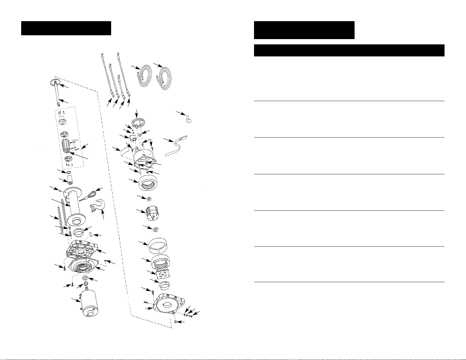
1 12 VDC Motor (inc. thru bolts) 90-33333 1
24 VDC Motor (inc. thru bolts) 90-33334 1
2 Motor Spacer 90-10354 1
3 Ball Bearing 94-23079-05 1
4 1/4-20 x 5/8 Self tapping hex head screw 90-23039-10 3
5 1/4-20 x 3/4 Socket Head Cap Screw 90-23055-06 2
6 Motor Adapter 90-32165 1
7 Outboard Drum Support w/ 10 90-32255 1
8 Drum Bearing 90-12575 1
9 Not applicable this model ——
10 Winding Direction Label 92-10211 1
11 Drag Button Spring 90-23152-08 1
12 Drag Button 90-22612 1
13 Tie Rod 90-20033 2
14 Drum 90-31069-04 1
15 M8 x 10 Socket Set Screw 94-23164-09 1
16 Drive Shaft Coupling 90-22110 1
17 Washer 90-23120-08 2
D Brake Assembly 90-25036 1
18 Not applicable this model ——
19 Not applicable this model ——
20 Not applicable this model ——
21 Not applicable this model ——
22 Not applicable this model ——
23 Not applicable this model ——
24 Not applicable this model ——
25 Not applicable this model ——
26 Not applicable this model ——
27 Drive Shaft Assembly 90-22254 1
28 Thrust Washer 90-12574 1
29 5/16 x 100 ft. Wire Rope w/o Hook 1580 1
30 Clevis Hook Assembly 94-20116 1
31 Inboard Drum Support 90-32168 1
32 Not applicable this model ——
33 3/8-16 Square Nut 90-23084-04 4
34 3/8 Flat Washer 92-23027-05 4
35 3/8 Lock Washer 92-23057-01 4
36 3/8-16 x 1 Hex Head Bolt, Grade 8 90-23226-01 4
37 1/4-20 x 3/4 Socket Head Cap Screw 90-23055-06 2
38 Drum Bearing 90-12575 1
39 Drum Driving Plate 90-22183 1
40 Output Ring Gear 90-32232-01 1
REPLACEMENT
PARTS LIST
Reference
Number Description Part Number Qty
WINCH ASSEMBLY
57
67
31
37
38
39
40
41
42
43
44
49
50
51
52
53
54
55
33
34
35
36
61
62
63
64
56
46
60
59
58
65
66
28
27
NOTE GROOVE
ORIENTATION
29
30
8
7
6
17
16
15
14
13
12
11
10
5
4
3
2
1
45
53
68
D
Figure 20
16
17
Reference
Number Description Part Number Qty
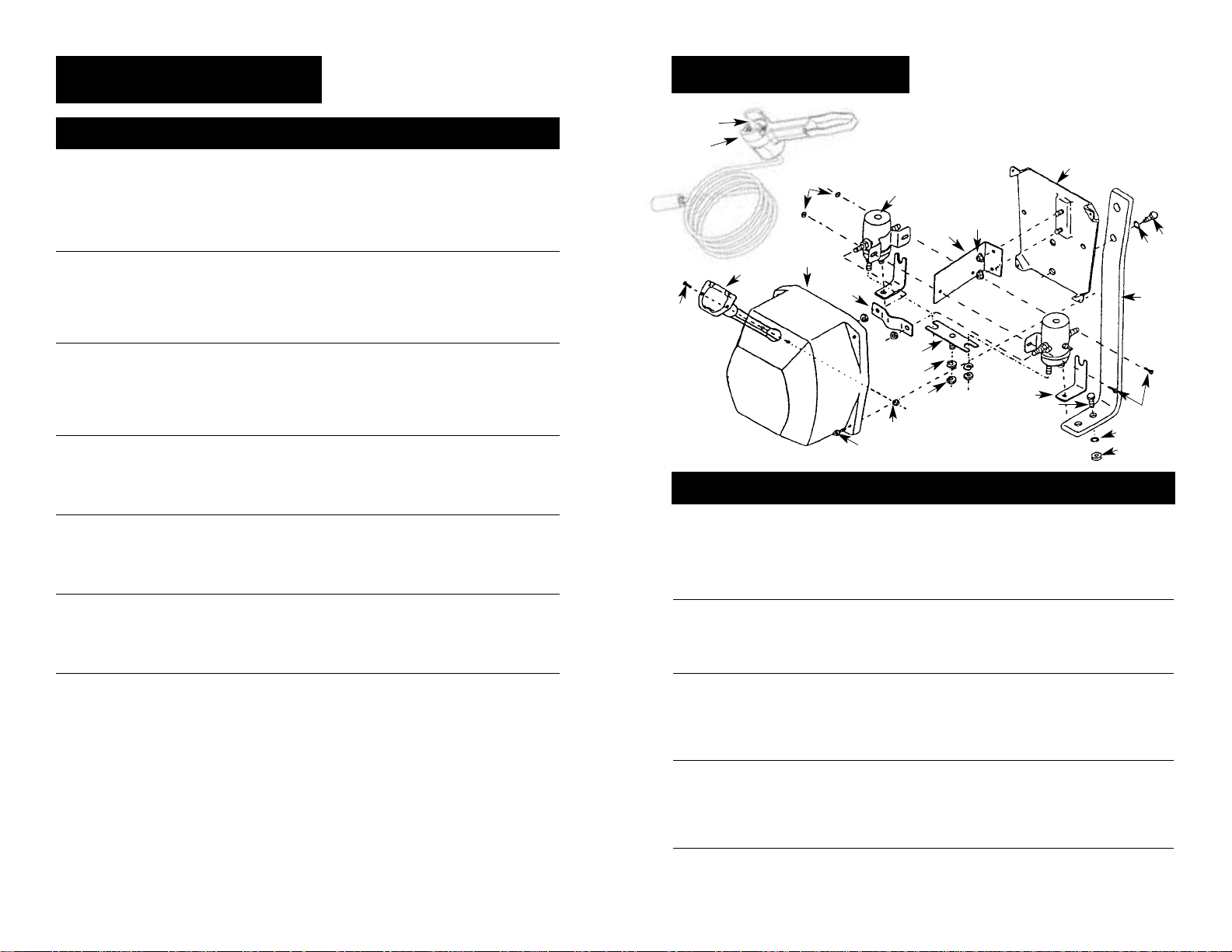
70 Remote Switch Pendant (15') 90-33450-01 1
71 Toggle Switch 90-14141 1
72 #8-32 x 3/4 Screw 90-23032-22 2
73 Connector Assembly w/ Wires 90-14140 1
74 Solenoid Cover (w/ Logo) 90-32187 1
75 #8-32 Hex Flanged Nut 90-23149-06 2
77 12VDC Solenoid 90-20329 2
24VDC Solenoid 90-20331 2
78 Top Bus Bar 92-12383 1
79 8-32 x 1/2 Self Tapping Screw 92-23039-01 4
80 5/16-18 Hex Nut 92-23034-04 1
81 5/16 Lock Washer 92-23057-03 1
82 Front Buss Bar w/ Stud 92-12384 1
83 Solenoid Bracket 94-20118 1
84 10-32 Flange Nut 90-23149-01 4
85 Solenoid Base Plate w/ Studs 90-22627-02 1
86 1/4-20 x 3/4 Hex Head Bolt 90-23226-10 4
87 1/4-20 Hex Flange Nut 90-23149-02 4
88 Solenoid Pack Bracket 90-31027-02 1
89 10-32 x 1/2 Machine Screw 92-23125-01 2
90 Buss Bar #1 92-20126 1
91 1/4 External Tooth Lock Washer 90-23227-02 2
NS X9 Logo 90-20065 1
NS Control Pack, X9 12V (includes 72-85, 89, 90) 90-32271 1
NS Control Pack, X9 24V (includes 72-85, 89, 90) 90-32272 1
SOLENOID ASSEMBLY
70
71
77
84
74
73
72
78
82
81
80
75
90
91
87
79
86
86
89
88
91
85
84
83
Figure 21
41 Ring Gear Bearing 90-22607 1
42 Carrier Bushing 90-10417 1
43 Planet Carrier Assembly 90-32238 1
44 Gearbox Bushing 90-10418 1
45 Plastic Closure 90-23171-05 2
46 8/32 x 3/8 Pan Head Screw 90-23032-17 1
47 Not applicable this model ——
48 Not applicable this model ——
49 Fixed Ring Gear 90-32233-01 1
50 Lock Pin 90-22252-01 1
51 Gearbox Housing (w/ 52, 56–58, 60
specify model no. when ordering) 90-32256 1
52 Warning/Clutch Operation Label
(specify model no.) 90-22263 1
53 1/4-20 x 5/8 Self Tapping Hex Head Screw 90-23039-10 4
54 Clutch Lever 90-32248 1
55 #8 Int. Tooth Lock Washer 90-23048-03 1
56 Dust Cover 90-22103 1
57 Plug 90-23171-07 1
58 Rubber Washer 92-10194 2
59 Clutch Spring 90-23152-07 1
60 Push-On Retainer 90-23213-04 2
61 2 AWG x 16" Lead Wire Assembly (yellow) 90-22695-26 1
62 2 AWG x 13" Lead Wire Assembly (blue) 90-22695-25 1
63 2 AWG x 10" Lead Wire Assembly (white) 90-22695-27 1
64 10 AWG x 24" Lead Wire Assembly 90-22635-33 1
65 2 AWG x 8' Lead Wire Assembly (black) 90-22635-47 1
66 2 AWG x 8' Lead Wire Assembly (red) 90-22695-46 1
67 2 AWG Boot Terminal 90-23247-04 3
68 Handsaver nylon cord 87-31120 1
NS 7" Long Wire Tie 94-23058-04 6
NS Grease (for one relube) 90-15020 1
NS Motor Brush Repair Kit 90-10414-05 1
ACC Roller Fairlead 2539 1
ACC Pulley Block, 20,000 lbs. 7750A 1
ACC Circuit Breaker Kit - 12 V 2232 1
ACC Circuit Breaker Kit - 24 V 2232A 1
NS Not Shown
ACC Accessory
REPLACEMENT
PARTS LIST
Reference
Number Description Part Number Qty
18
19
70
71

USA
Superwinch Inc.
Winch Drive
Putnam, CT 06260
phone: 860-928-7787
repair@superwinch.com
Electric Motor Repair
2010 North 4th Street
Minneapolis, MN 55411
phone: 612-588-4693
Berens & Associates
124 Hegenberger Loop
Oakland, CA 94621
phone: 800-540-2858
berens94621@yahoo.com
Zorko’s Alternator Service
241 Wells Road
Home, PA 15747
phone: 800-468-5055
zasapw@microserve.net
Electric Motors of Iowa City
50 Commercial Court
Iowa City, IA 52246
phone: 319-354-4040
emic4040@aol.com
CANADA
Demand Electric
228-39th St. N.E.
Calgary, AB T2E 2M5
403-230-2709
Harold Supply
3 Southerland Ave.
Sudbury, Ont. P3C 3A7
705-761-4455
Explora Industries Ltd.
9605-5th Ave.
Edmonton, AB T6E 0B2
780-430-8591
Dayworth Sales
1 Saunders Rd. Unit 2
Barrie, Ont. 9A7 9A7
705-726-7778
Les Equipment Twin
10401 Parkway Blvd.
Ville D’Anjou, PQ H1J 1R4
514-353-1190
Buffalo Industries
251-253 Princess Street
Winnipeg, Manitoba R2C 1M1
204-942-1951
Power Plus Tool Repair
57 Millenium Ave.
Moncton, NB E1E 2G2
560-855-8665
Muskoka Auto Parts
11 King William St.
Huntsville, Ont. P1H 2K8
705-789-2321
Lou Dennis Auto
Hiway 11 South
Sundridge, Ont. P0A 1Z0
705-384-5345
Outdoors Plus
128 Regional St.
P.O. Box 1349
Port Aux Basques, NF A0M 1C0
709-695-7533
Bobcaygeon Auto and Marine
91 Main St.
Bobcaygeon, Ont. K0M 1A0
705-738-2317
MAP Bracebridge
19 Taylor Rd.
Bracebridge, Ont. P1L 1W3
705-645-8785
MAP Fenelon Falls
165 Lindsay St.
Fenelon Falls, Ont. K0M 1N0
705-887-6232
Central Electric Motor Rewind
#1-1960 Windsor Rd.
Kelowna, NC V1Y 2Y3
250-860-4415
jnelsoncentral@netscape.net
Delta Tool Repair Limited
114-7533, 135th St.
Surrey, BC V3W 0N6
604-591-3230
Ted's Power Tool Repair
426-44th St. East
Saskatoon, SK S7K OW1
306-934-6155
Bob's Electric Truck Servise
845-B Macdonald Ave.
Regina, SK S4N 2X5
306-721-4148
Off Road Canada
251-12th St. "B" North
Lethbridge, AB T1H 2K8
403-327-7722
Gary's Starter & Alternator
P.O.Box 7 Site 4
RR 1 Mount Uniacke B0N 1Z0
Contact: Gary Thorne
902-757-2388
Power Blitz Mftg. & Maintenance
577 Edgeley Blvd. Unit 6
Concord, Ont. L4K 4B2
905-669-8209
ali@powerblitz.com
Bruce's Recreaction
92 Balbo Dr.
Shoal Harbour Nfld A5A 4A8
709-466-3355
Atlantic Recreation & Marine
5 School St.
Sydney, Nova Scotia
B1S 3G1
902-567-1697
sbidart@thearm.ca
UNITED KINGDOM
Superwinch, LTD
Abbey Rise, Whitchurch road
Tavistock, Devon PL19 9DR
+44 (0) 1822 614101
WORLDWIDEContact your Local
Superwinch Distributor or callSuperwinch.
TROUBLESHOOTING
CHART
Motor will not operate 1. Damaged or stuck 1.
CAUTION:
Disengage
or runs in one direction solenoid; most likely clutch before performonly caused by not holding ing this test to prevent
the inner nut to keep the powering the wire rope
stud from turning when drum. If a solenoid sticks
attaching wire to solenoid once, it is likely to stick
again and must be
replaced immediately.
Tap solenoid to free
stuck contacts. Check
by applying voltage to
the small solenoid terminal. Be sure solenoid
is grounded back to
source. A solenoid that
is not stuck will make an
audible “click” when first
energized
2. Switch inoperative 2. Replace Switch
3. Broken wires or bad 3. Check for poor connectconnection tions.
CAUTION: Always
use two wrenches
(spanners). (See Figure 10)
4. Damaged motor 4. Replace or repair motor
5. Solenoids not grounded 5. Check the ground path
between battery
negative and solenoid base
Winch will not shut off 1. Solenoid stuck “on” 1. If solenoid sticks on,
reverse direction and hold
trigger switch on until the
power lead can be disconnected. A safety on-off
switch is available as an
accessory
Motor runs extremely hot 1. Long period of operation 1. Allow to cool
2. Damaged motor 2. Replace or repair motor
3. Damaged brake 3. Replace or repair brake
Motor runs but with 1. Weak battery 1. Recharge or replace
insufficient power or battery. Check charging
line speed system
2. Battery to winch wire 2. Use larger gauge wire
too long
3. Poor battery connection 3. Check battery terminals for
corrosion. Clean as
required
4. Poor ground 4. Check and clean connections
5. Damaged brake 5. Repair or replace brake
Motor runs but drum 1. Clutch not engaged 1. Engage clutch
does not turn
Winch runs backwards 1. Motor wires reversed 1. Recheck wiring
2. Solenoids wired incorrectly 2. Recheck wiring
Will not hold load 1. Excessive load 1. Reduce load or double line
2. Worn or damaged brake 2. Repair or replace brake
Symptom Possible Cause(s) Corrective Action
If a problem arises, contact your nearest
Superwinch dealer or repair center.
20
21
WARRANTY REPAIR CENTERS
 Loading...