

Page 1
Owners Manual 5-201-001 Issue 3 1Page
Superwinch LTD.
Union Mine Road, Pitts Cleave
Tavistock, Devon. PL19 0NS
Tel: +44 (0) 1822 614101
Fax: +44 (0) 1822 615204
E-mail: [email protected]
Superwinch LLC.
359 Lake Road, Dayville
CT06241 U.S.A.
Tel: 01 800 323 2031
Fax: 01 860 963 0811
E-mail: [email protected]
w w w . s u p e r w i n c h . c o m
EN 14492-1
EN 14492-1
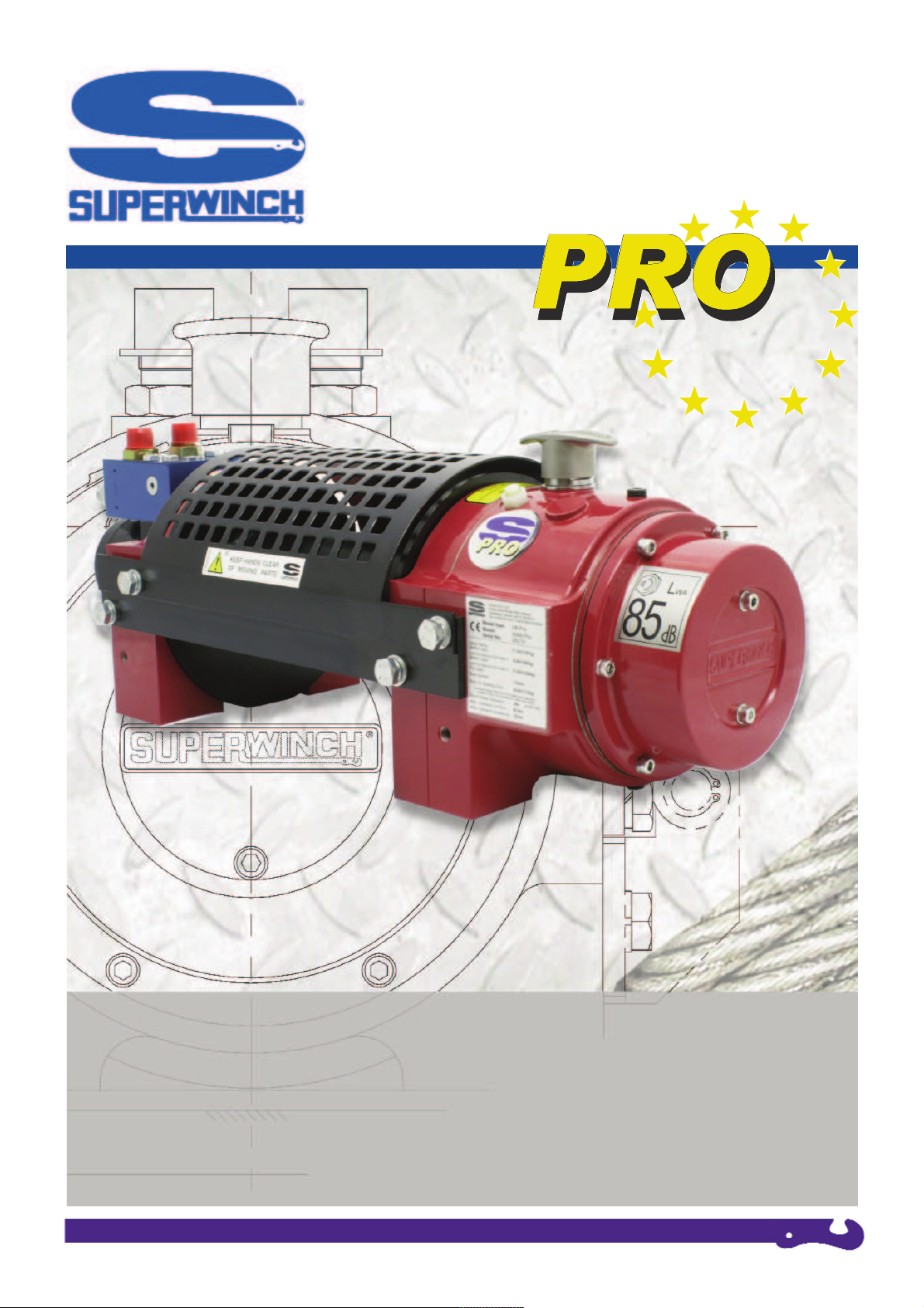
OWNER’S MANUAL
H8P-PRO / H10P-PRO
HYDRAULICALLY POWERED WINCHES
Winch shown for
illustration purposes only
Page 2

Owners Manual 5-201-001 Issue 3 2Page
Owner’s Manual
5050-PRO, H8P
5060-PRO, H8P
650006-PRO, H8P
5170-PRO, H10P
5172-PRO, H10P
These instructions cover kits from
01/01/2010
01 INTRODUCTION
02 GENERAL SPECIFICATION DATA
03 INSTALLATION
HYDRAULIC SYSTEM
WINCH
CABLE
04 MAINTENANCE AND USE
FREESPOOL USE
RUNNING IN, MAINTENANCE & SERVICING
TIPS FOR EXTENDING THE LIFE OF YOUR WINCH
05 SPARES & ACCESSORIES
06 WARRANTY
07 NOTES
For all your requirements please contact your Superwinch agent
i
Page 3

Owners Manual 5-201-001 Issue 3 3Page
Thank you for purcha sin g a Superwinch Pro. It has
been designed and manufactured to meet BS EN 14492-1,
Power Driven Winches Standard, and provide years of
trouble-free operation.
Please read and understand this Owner’s handbook before
using your winch. Your winch is a very powerful machine. If
used unsafely or improperly, there is a possibility that property
damage or personal injury can result. We have included
several unique features in the winch to minimize this
possibility, however, your safety ultimately depends on your
caution when using the product. Correct installation of your
winch is a requirement for correct operation. Pay particular
attention to the winch installation section in this handbook.
Congratulations on your choice.
These instructions are designed to assist skilled technicians in
the efficient installation of a Superwinch, using the
appropriate trade tools. Superwinch reserve the right to alter
model specification without prior notice.
PLEASE RETAIN THIS HANDBOOK WITH THE WINCH
WARNINGS, CAUTION AND NOTES
These are given through these instructions in the following
form :
WARNING : Procedures which must be followed
precisely in order to avoid the possibility of
personal injury.
CAUTION : This calls attention to procedures
which must be followed to avoid damage to
components.
NOTE : This calls attention to methods which make
a job easier or gives helpful information.
USAGE OF WINCH
This winch is designed for use in applications such as Pulling,
Hauling, and other associated uses.
REPAIRS AND REPLACEMENTS
Before you contact Superwinch or your nearest Dealer please
have ready the following information: Kit No, Serial No, and
Part No. required
POISONOUS SUBSTANCES
Many liquids and other substances used should under no
circumstances be consumed, and should be kept away from
open wounds. These substances include (amoung others)
hydraulic oil.
SYNTHETIC RUBBER
Many ‘O’ ring seals, flexible pipes and similar items, when
subjected to fire or heat can become highly corrosive. Handle
with seamless gloves only. Should skin contact occur, remove
contaminated clothing immediately and obtain medical
assistance without delay. Meanwhile, wash the affected area
with copious amounts of cold water or limewater for 15 to 60
minutes.
RECYCLING AND THE ENVIRONMENT
It is illegal to dispose of used oil in the ground, down sewers
or drains or into waterways. Dispose of used oil through
authorised waste disposal contractors. If in doubt contact your
local Authority for advice on disposal facilities.
GENERAL DESCRIPTION
The winch is hydraulically driven from a hydraulic system.
See Hydraulic Installation section. The drum can be
disengaged, to enable the rope to be pulled out easily and
quickly. The winch is equipped with an adjustable freespooling damper to help alleviate the possibility of wire rope
over-run on the drum.
The automatic disc brake is housed in the planetary gearbox.
The brake will activate automatically to prevent the load from
causing the winch to ‘back-drive’. The brake itself is self
adjusting for wear and is oil immersed for optimum heat
dissipation. The brake lining are of high performance nonasbestos material.
The winch is reversible with ‘power-in’ and ‘power-out’ via a
directional control valve mounted on the vehicle. The standard
unit is supplied with, counter-clockwise drum rotation on
‘winch-in’ when viewed from the gearbox end. The winch can
be used in both ‘over-wound’ and ‘under-wound’ conditions.
01
INTRODUCTION
IMPORTANT: Superwinch winches are not to
be used to lift, support or otherwise transport
personnel. Any such use shall be considered
to invalidate the warranty and Superwinch
shall not be responsible for any claims arising
from such use.
Page 4

Owners Manual 5-201-001 Issue 3 4Page
Model Designation H8P H8P H10P H10P
Standard Drum Long Drum Standard Drum Long Drum
Part No: 5050PRO 5060PRO 5170PRO 5172PRO
650006PRO
Weight (Less Rope): 42 kg 45 kg 42 kg 45kg
Recommended Rope Diameter: 10 mm 10 mm 11 mm 11mm
Drum Capacity: 27 M 36 M 20 M 26 M
Drum Diameter (10:1 D:d ratio): 90mm 90mm 101.6mm 101.6mm
Line Speed (1st Layer, No Load): 14.7 M/min 14.7 M/min 10.0 M/min 10.0 M/min
Line Pull (Bottom Layer): 34.9 kN 34.9 kN 42.16 kN 42.16 kN
Maximum Oil Pressure: 155 bar 155 bar 155 bar 155 bar
Maximum Oil Flow: 60 L/min 60 L/min 60 L/min 60 L/min
Freespool Manual Manual Manual Manual
To ensure that winches are compliant with the European standard, BS-EN14492-1 Superwinch recommends that wire ropes
should be as follows:
10mm dia for H8P winch with a tensile grade of 1960 and a min break figure of 7,119kg (69.8kN)
11mm dia for H10P winch with a tensile grade of 1960 and a min break figure of 8,608kg (84.4kN)
02
SPECIFICATION DATA
Gear Reduction: High efficiency planetary for optimum reliability.
Drum: Fabricated steel mounted on maintenance free plain bearings.
Braking: Full Load Holding.
Mounting: Designed to most industry standard dimensions, this winch can be side,
foot or angle mounted, flat bed or low mount.
Pneu. Freespool Supply Pressure: 5.5 bar.
Load Limiter: Hydraulic system relief valve on vehicle (installers responsibility).
Labelling: Rating Plate showing 1st layer and top layer figures.
Roller Fairlead warning label.
Page 5
Owners Manual 5-201-001 Issue 3 5Page
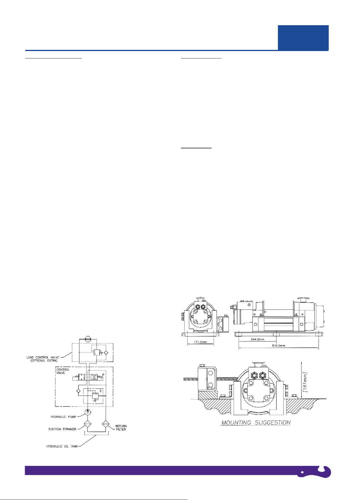
HYDRAULIC SYSTEM
System Type: Open system with filtered return line
Relief Valve: IMPORTANT - Set at winch operating pressure
Pump: With a maximum oil supply of 60 l/min at top motor rpm. The
pump must be capable of delivering a pressure of 170 bar.
Reservoir: Must be fitted with an oil filter device comprising strainer
and air filter and a dip stick. The capacity of the tank should be at
least 60 litres (16 U.S. gal). Note: Do not fill the tank to the top, since
there must be space for expansion in the tank. Suitable hydraulic oil
is Castrol CRML or equivalent (150 LHM 32 - 68). Typical viscosity
rating of 150 - 175 cSt at 100°c.
Hoses: Should have the minimum following dimensions:
Pump inlet line: 32 - 38mm (1 1/4” - 1 1/2”)
Nominal Bore (N.B.)
(reservoir to pump)
Return line: 25mm (1”) N.B.
(control valve to reservoir)
Pressure hoses: 13mm (1/2”) N.B.
(control valve to load control valve)
Pressure and flow loss is increased as hose length increases and/or
bore size decreases. Pressure and return lines in excess of 3.5 meters
should be compensated with an increase in nominal bore size.
Control Valve 4 - way, 3 - position with spring centred, open centre
(ports A & B open when in centre position) and built in relief valve.
The relief valve must be set to the winch operating pressure. The
valve should be mounted as close to the winch as possible
Load Control Valve: A single overcentre valve is fitted to the winch
to give smoothly controlled winch out when under load and to
provide full dynamic braking.
Oil Suction Strainer Rating: Approximately 250 microns
Return Line Filter Rating: 10 - 40 microns
INSTALLATION
As a general rule:
Bigger Nominal Bore Hose = Better Winch Performance
In all installation work on a hydraulic system, cleanliness and
accuracy are essential so that the hydraulic system functions
properly.
All winch systems must be protected by an efficient Emergency
Stop system, hydraulic winches should be fitted with a highly
visible engine kill system to stop the vehicle engine driving the
hydraulic system.
MOUNTING
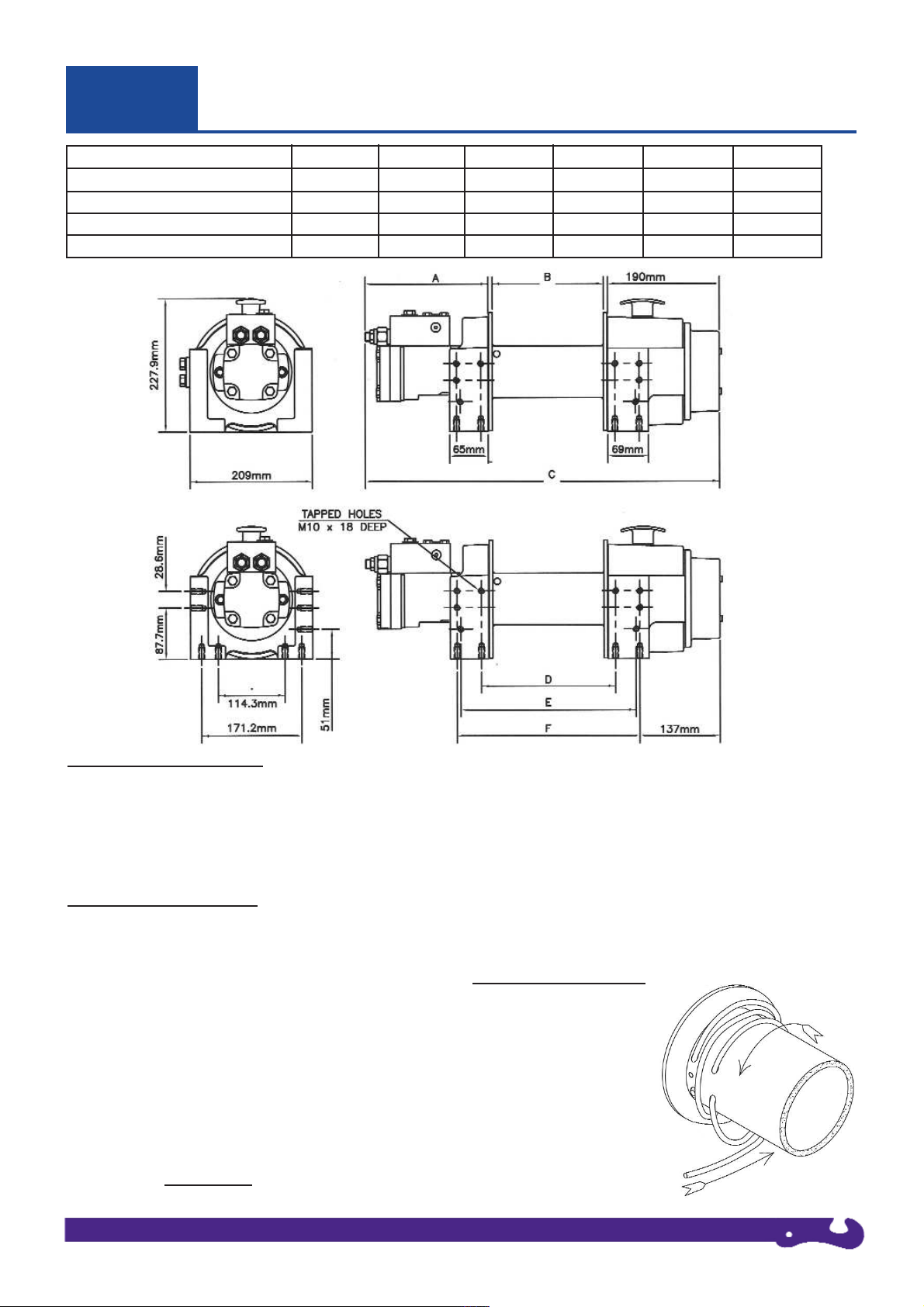
The diagrams on page 6 show the mounting dimensions for the
Superwinch H8 and H10P.
The side and feet mounting hole positions are designed to allow the
winch to be interchangeable with the most popular 8000 - 10000 lbs
units currently available. The diagram below shows the H8P or H10P
mounted on a Superwinch flatbed mounting kit (Part No. 5625),
shown with Roller Fairlead. If a Superwinch mounting plate is not
used, the surface must be flat within 0.5 mm and sufficiently stiff to
prevent flexing. A minimum of 6.0 mm thick steel plate should be
used. The thicker the plate, the better the alignment between motor
mounting, drum and gearbox housing.
It is important that the winch is mounted securely so that the motor
mounting, drum and gearbox housing are accurately aligned. Be sure
the winch will not move under load, otherwise you may cause
misalignment in the winch, causing the drum to bind up.
The tie bars supplied with the winch must remain attached when the
winch is foot mounted. Angle mounting is possible and
recommended for maximum flexibility in mounting. These mounts
allow the winch to be low-mounted. See the diagram below.
Mounting / Fixing hole details:
M10 thread, depth of full thread: 20mm.
Please ensure depth of thread engagement: 15mm.
03
WINCH INSTALLATION
Page 6
Owners Manual 5-201-001 Issue 3 6Page
03
WINCH INSTALLATION
VERSION A B C D* E F*
H8P - 190mm DRUM LENGTH 207.0mm 190.0mm 602.0mm 228.5mm 298.5mm 311.0mm
H8P - 253mm DRUM LENGTH 207.0mm 253.0mm 665.0mm 291.5mm 361.5mm 374.0mm
H10P -190mm DRUM LENGTH 214.0mm 190.0mm 609.0mm 228.5mm 298.5mm 311.0mm
H10P - 253mm DRUM LENGTH 207.0mm 253.0mm 665.0mm 291.5mm 361.5mm 374.0mm
WIRE ROPE SPECIFICATION
The rope must be of good quality, have a steel core and meet the
specification detailed on the certificate of conformity.
Avoid pulling a load at more than a 15 degree angle in relation to
the winch. This will reduce wear and tear on the winch and the
cable.
WIRE ROPE INSTALLATION
1. Remove Rope Drum safety guard.
2. Unwind the cable by rolling it out along the ground
with the tapered end nearest to the winch. NEVER wind the cable
straight onto the drum from a coil.
3. Raise the cable tensioner away from the rope drum (if supplied
as part of your kit), and lock in position through the corresponding
holes in the tensioner frame and bracket using a suitable pin or bolt.
4. Rotate the rope drum under power until the rope fixing holes run
vertically at the front of the winch.
5. Pass the rope end through the roller fairlead, under the drum and
back over the top of the drum to pass through the rope hole furthest
way from the drum flange. Keep feeding the rope through to wrap
around the drum FOUR TIMES
and into the rope fixing hole
nearest the drum flange.
6. Tighten the retaining screw ensuring that the rope end is flush
with the exit of the hole and not protruding.
7. Feed back any excess slack to tighten the four wraps neatly on
the drum.
8. Remove the locking pin from the cable tensioner to allow the
rollers to rest on the rope. Note: This assembly is under tension.
Special care should be taken to avoid trapping fingers, clothing etc.
9. Apply moderate tension to the rope. Take care to ensure the
layers are neatly wrapped, as this will minimise damage to the
lower layers of rope when a load is applied.
PULLING OUT THE ROPE
Dis-engage the freespool. With
a pair of gloves on, pull out the
rope and secure to anchor or
load. Re-engage the freespool.
Note: Two wraps illustrated
for clarity.
Page 7
Owners Manual 5-201-001 Issue 3 7Page
04
MAINTENANCE & USE
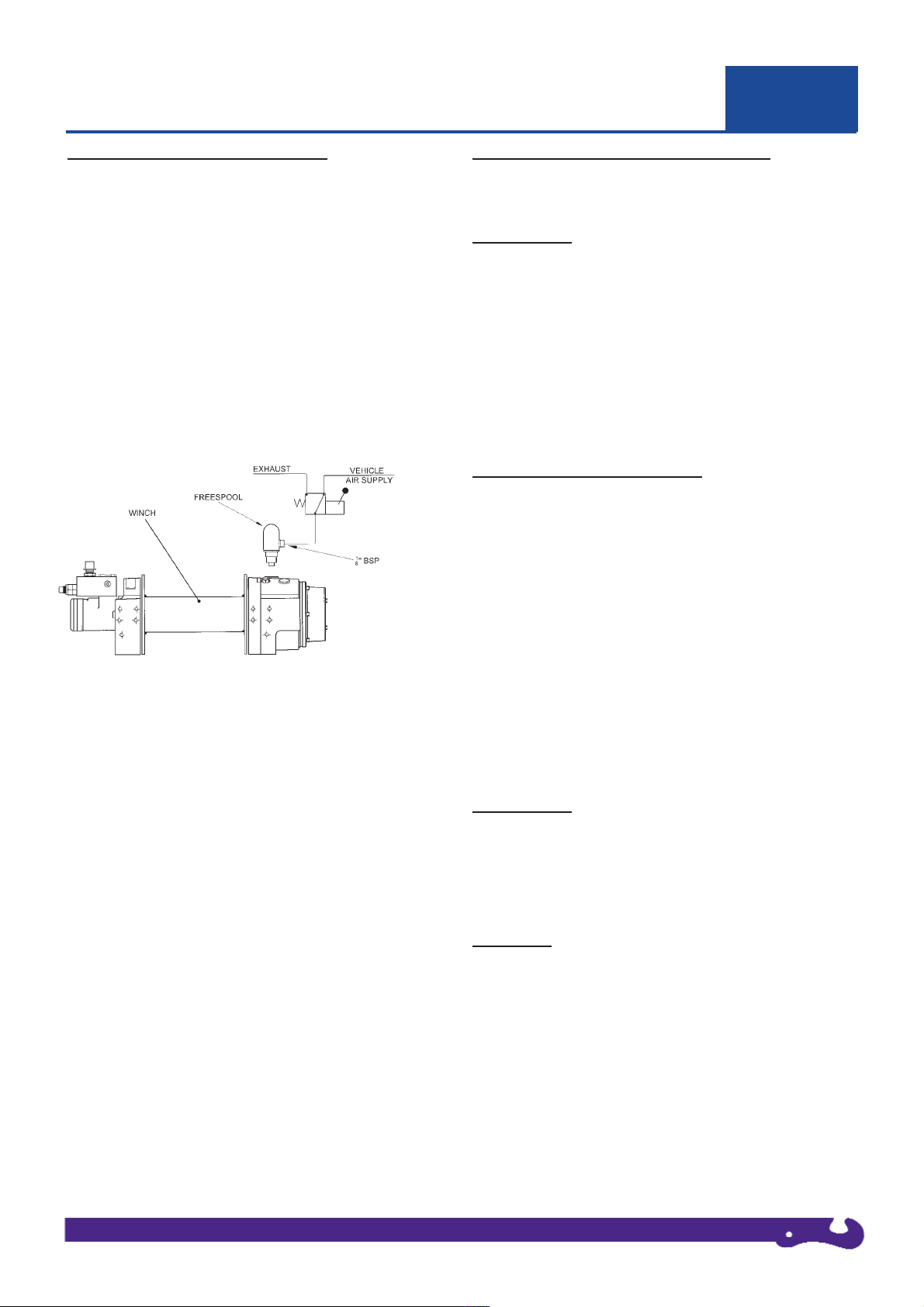
PNEUMATIC FREESPOOL OPERATION
1. Dis-engage the drum by operating the pneumatic control valve.
2. Pull out the cable by hand, but leave at least 5 wraps on the drum.
3. Attach the load.
4. Engage the drum by moving the control valve lever to the
appropriate position. The freespool mechanism will spring return
but the drum will not engage until it has been rotated a little, by
hand. Do not attempt to pull a load until the drum is properly
engaged.
Note: The mechanism is designed such that it cannot be disengaged when the drum is underload.
5. Operate the winch.
MANUAL FREESPOOL OPERATION
1. To dis-engage the freespool (if engaged) pull the knob and turn
90° ensuring that the knob stays out.
2. Pull out the cable by hand, but leave at least 5 wraps on the drum.
3. Attach the load.
4. Engage the freespool by turning the knob 90° and then rotating
the drum by hand until the knob springs in.
Do not attempt to pull a load until the drum is properly engaged.
5. Operate the winch.
RUNNING IN, MAINTENANCE & SERVICING
For optimum performance all hydraulic motors need running in. Run
for approximately 1 hour at 30% of maximum oil pressure.
LUBRICATION
Freespool Handle (manual freespool version) lubricate regularly
with light oil.
Drum Bearings - These are self-lubricating but are lubricated with
molydisulphide loaded bearing grease when assembled.
Gearbox - The gearbox is prefilled with BP Energol GR-XP 150 or
equivalent at the factory, this is suitable for temperate climate use. If
the winch is to be used in a different ambient temperature range then
please consult the list below and select and use the appropriate grade
oil.
ROUTINE SERVICE INSPECTIONS
IMPORTANT - Ensure your winch has been filled with oil before
use.
The following inspections should be carried out during routine
vehicle servicing:
1. Check the oil level in planetary gear box. Oil level should be
maintained. The oil specification recommended is BP Energol GRXP150 or equivalent, using approximately 0.5 litre.
2. Check the tightness of mounting bolts and all hydraulic
connections; remove any dirt or corrosion that may have
accumulated. Check the winch for operation in both directions.
3. Repairs should be carried out by authorised Superwinch repair
centres only. Do not attempt disassembly of the gearbox.
Disassembly will void warranty.
LUBRICATION
CLIMATE TEMPERATURE PLANETARY
GEARBOX
Arctic -20°C to 25°C Energol GR-XP100
Temperate 5°C to 40°C Energol GR-XP150
Tropical 13°C to 65°C Energol GR-XP220
SERVICING
Before you contact Superwinch or your nearest Dealer for parts,
please have ready the following information:
* Kit No. * Serial No. of Winch * Part No. Required
When ordering spare parts from these lists, always quote the winch
serial number and the part number not item number of the spare part
required. This will ensure the correct part is despatched to you. The
serial number of your winch is located on the data plate on the motor
support casting.
Page 8
Owners Manual 5-201-001 Issue 3 8Page
04
MAINTENANCE & USE
TIPS FOR EXTENDING THE LIFE OF YOUR WINCH
1. Note: Installing the wire rope is not included in the running-in
period. Check tightness of all mounting bolts after running-in
period.
2. Keep a tightly wound rope drum. Do not allow the windings
on the drum to become loosely wound. A loosely wound spool
allows a rope under load to work its way down into the layers of
the wire rope on the drum. When this happens, the lower layers
become damaged and the rope may become wedged within the
body of the windings. To prevent this problem, keep tension on
the rope at all times. A good practise is to rewind the rope under
tension after each use.
3. Prevent kinks before they occur.
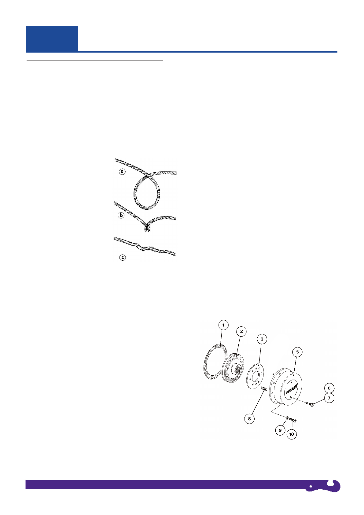
a) This is a start of a kink. At this
time, the rope should be
straightened.
b) The rope was pulled and the
loop has tightened to a kink. The
rope is now permanently
damaged.
c) The result of kinking is that
each strand pulls a different
amount causing the strands under
greatest tension to break and
reduce load capacity of the wire
rope.
4. Use a snatch block for heavy loads. To keep wear to a
minimum, use a snatch block to double line heavy loads. Double
lining reduces the work required of the gears by one half which
in turn reduces wear.
5. The pull required to start a load moving is often much greater
than the load to keep it moving. Try to avoid stopping and
starting during a pull.
FRICTION PLATE ASSEMBLY REPLACEMENT
1. Drain gearbox oil.
2. Remove two screws, Item 7, in Clutch Cover, Item 5.
3. Replace with two screws, M5 x 0.8 pitch x 40mm long,
shortened to 38mm long.
4. Unscrew six screws, Item 10, and remove Clutch Cover, Item 5
complete with Clutch Plate, Item 3.
Do not remove clutch plate from clutch cover.
5. Slide Friction Plate Assembly, Item 2, from Input Shaft.
6. Replace Friction Plate Assembly, Item 2, ensuring that boss is
facing away from gearbox.
Ensure Roll Pins in Clutch Housing Cover (Item 5), align holes
in clutch plate.
7. Replace gasket, Item 1, and Clutch Cover Assembly.
8. Tighten six screws, Item 10.
9. remove two screws securing the Clutch Plate to Clutch Cover,
and replace two screws, Item 7, complete with seals.
CLUTCH SPRING REPLACEMENT/REMOVAL
1. Follow steps 1 to 4 under the procedure for Friction Plate
Assembly Replacement, described above.
2. Slacken the two Clutch Plate holding screws, carefully. Remove
the Plate, Item 3, to reveal six springs, Item 8.
3. Replace springs.
4. Replace Clutch Plate, Item 3, ensuring roll pins, Item 4, align
with holes in Clutch Plate.
5. Replace the two Clutch Plate holding screws, tighten to draw
plate down on the springs, ensuring roll pins align with holes in
Clutch Plate.
6. Follow steps 7 to 9 under the procedure for Friction Plate
Assembly Replacement, described above.
Item Qty PART No. Description
1 2 10063 Gasket
2 1 10028 Friction Plate Assembly
Drawn Cup Clutch
3 1 10002 Clutch Plate
5 1 50-90622-01 Clutch Cover Assy
6 2 4-23-063 Thread Seal
7 2 4-36-0601022 Cap Head Screw M6 x 10
8 6* 4-31-1403030403 Spring
9 6 4-51-0623 Spring Washer M6
10 6 4-36-0603022 Cap Head Screw M6 x 30
* Model 5072H = 2 Springs
Page 9
Owners Manual 5-201-001 Issue 3 9Page
05
SPARES & ACCESSORIES
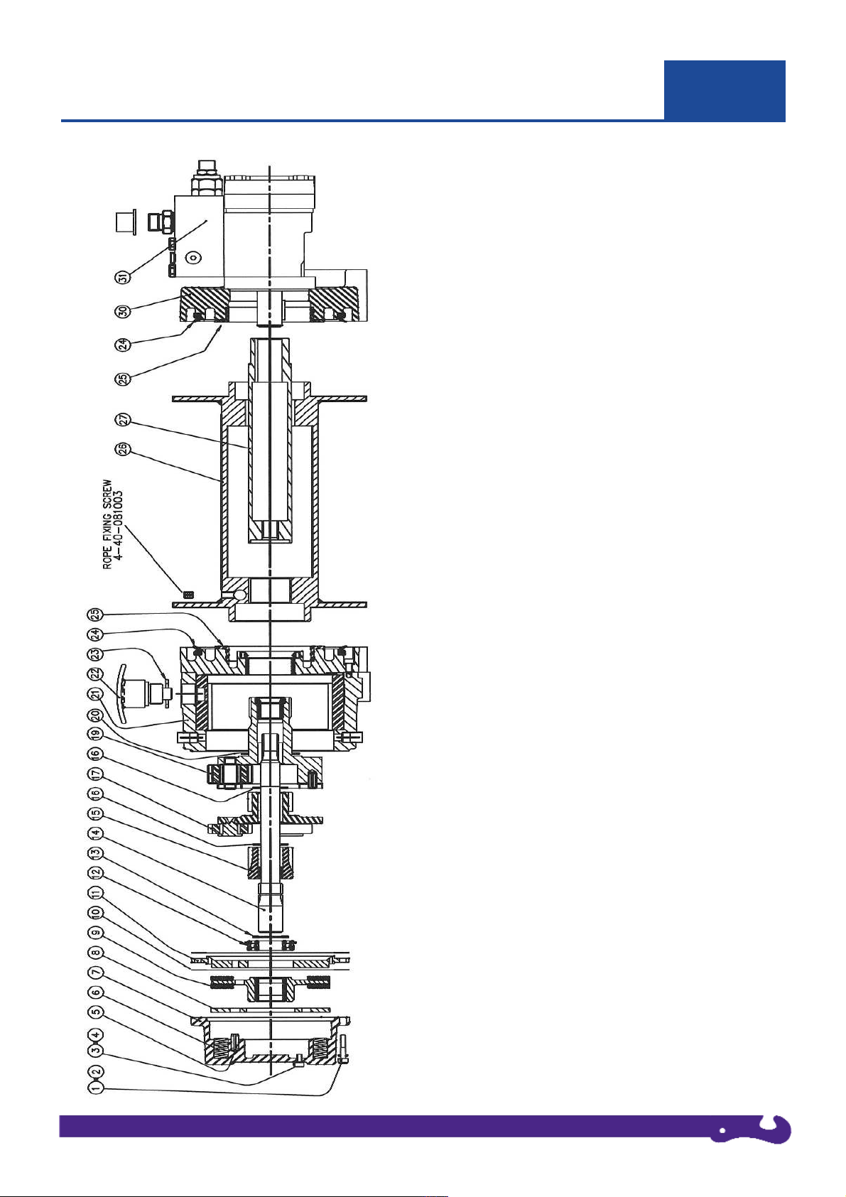
H8P / H10P SERIES WINCHES, GENERAL ASSEMBLY, WITH LOAD CONTROL VALVE
Item Description Part No. Qty.
1 Cap Hd Screw 4-36-0603022 6
2 Spring Washer 4-51-0623 6
3 Cap Hd Screw 4-36-0601022 2
4 Screw Seal 4-23-063 2
5 Roll Pin 4-56-802003 3
6 Spring 4-31-1403030403 6
7 Brake Housing 50-90622-01 1
7 Brake Housing, (5052Gg, only) 50-25160 1
8 Pressure Plate 10002 1
9 Friction Plate Assy 10028 1
10 Gasket 10063 2
11 Bearing Plate & Ball Bearing 50-95074 1
12 Ball Bearing Part of 50-95074 1
13 Snap Ring 4-26-2517123 1
14 Drive Shaft 50-50056 1
15 Sun Gear 50-54013 1
16 Thrust Washer 10006 2
17 1st Stage Carrier Assy 10061 1
19 2nd Stage Carrier Assy 10011 1
20 Thrust Washer 10051 1
21 Gear Housing Assy 50-90547 1
22 F / Spool Assy, Manual 10076 1
22 F / Spool Assy, Air 5603 1
22 No F / Spool Plug 10280 1
23 Washer 10295 1
24 Face Seal 4-22-140161123 2
25 Drum Bearing 10049 1
26 Drum Assy, 190mm (H8P) 50-90684 1
26 Drum Assy, 253mm (H8P) 50-90685 1
26 Drum Assy, 190mm (H10P) 50-90708 1
26 Drum Assy, 253mm (H10P) 50-90688 1
27 Coupling Tube, 190mm 50-90014 1
27 Coupling Tube, 253mm 50-90015 1
30 Support Housing 50-90424 1
31 Motor / Block Assembly (H8P) 50-90425 1
32 Motor / Block Assembly (H10P) 50-90604 1
n/s Tie Bar, 190mm 50-52006 2
n/s Tie Bar, 253mm 50-52007 2
Page 10

Optional accessories, designed by Superwinch exclusively for the H8 and H10P:
Owners Manual 5-201-001 Issue 3 10Page
05
OPTIONAL ACCESSORIES
Winch accessory kit
Part No. 0505
Stowage Bag (nylon)
Pulley Block
Nylon Sling
Bow Shackles x 2
Pair of Leather Gloves (Heavy Duty)
Flatbed Mount Plate
Part No. 5625 with mounting bolts
For illustration purposes only
Pulley Block, 9000kg
Part No. 7750
Roller Fairlead
Part No. 5600
Standard Drum
190 mm Drum Length
Roller Fairlead
Part No. 5610
Long Drum
253 mm Drum Length
Pneumatic Freespool
Part No. 5603
Bow Shackles
Part No. 0509
Wire Rope, 10mm x 23m
Part No. 0561S
Wire Rope, 10mm x 30m
Part No. 0563S
Wire Rope, 10mm x 40m
Part No. 0582
Wire Rope, 11mm x 23m
Part No. 0545
Synthetic Rope
10mm x 30m
Part No. 771030
Synthetic Rope,
11mm x 30m
Part No. 771230
Cable Tensioner
Part No. 5606
Short Drum
190 mm Drum Length
Cable Tensioner
Part No. 5607
Long Drum
253 mm Drum Length
Rope Drum Safety Guard
Part No. 50-30171, Standard Drum
Part No. 50-30172, Long Drum
Page 11

Owners Manual 5-201-001 Issue 3 11Page
SUPERWINCH LIMITED WARRANTY VALID WORLD WIDE
Limited Warranty. Superwinch (“seller”) warrants the original buyer (“you”) all parts and components except wire rope to be
free from defects in materials and workmanship for a period of (one) 1 year from the provable date of purchase. Any Superwinch
product which is defective will be repaired or replaced without charge to you, upon compliance with these procedures. The
warranties set forth herein are exclusive and inlieu of all other warranties, whether oral or written, express or implied.
Limited Warranty Performance Procedure. Upon discovery of a defective Superwinch product, you shall mail to the seller
at his factory or any factory authorised service centre written notice of such defect and mail, ship or otherwise deliver the
defective Superwinch, postage or shipping prepaid. Repairs or replacements by seller under this Limited Warranty will normally
be accomplished within (fifteen) 15 business days after receipt of the defective Superwinch. Seller or its authorised agents may
make reasonable charges for parts and labour not covered by this Limited Warranty.
Warranty and Remedy Limitations and Exclusions. Repair and/or replacement of the defective Superwinch or component
thereof as provided herein is the exclusive remedy for the buyer. The following exclusions or limitations of warranties and
limitations of remedies shall be expressly applicable:
A. Express Warranties. Seller warrants that the Superwinch is as described in the “Superwinch Owner’s Manual” provided
herein; no other express warranty is made in respect to the Superwinch. If any model or sample was shown to the buyer, such
model or sample was used for illustrative purposes only, and shall not be constructed as a warranty that the Superwinch will
conform to the sample or model. Seller makes no express warranty with respect to wire rope incorporated in the product.
B. Implied Warranties. The implied warranty of merchantability and all other implied warranties shall only extend from
the provable date of purchase for (one) 1 year. The wire rope is sold “as is”, without any implied warranties. Some States
within the USA do not allow limitations on how long an implied warranty lasts, so the above limitation may not apply to
you.
C. Incidential and Consequential Damages. Subject to seller’s Limited Warranty obligations set forth herein, seller shall
not be responsible for incidential damages of any kind, or the consequential damages to property, loss of profits and loss
of use which may be caused by any defect in, or malfunction, or failure of enclosed Superwinch. Some States within the
USA do not allow exclusion or limitation of incidential or consequential damages, so the above limitation or exclusion
may not apply to you.
D. Condition of Warranty. Seller shall not be required to comply with its warranty duties provided herein if the defect,
malfunction, or failure of the Superwinch was caused by damage (not resulting from defective or malfunctioning components)
or unreasonable use by you. Unreasonable use shall includem but it not limited to, installation or use of the Superwinch wihtout
compliance with the instructions contained in the Superwinch Owner’s Manual for the particular model number. Seller’s liability
under this warranty or for any loss or damage to the Superwinch product shall not exceed the cost of correcting defects in or
replacing the Superwinch product, and upon expiration of the warranty period, all such liatbility shall terminate. The agents,
dealers and employees of the seller are not authorised to make modifications to this warranty, or additional warranties binding
on the seller. According additional statements, whether oral or written, do not constitute warranties and should not be relied
upon.
Legal Remedies of Buyer. This Limited Warranty gives you specific legal rights, and you may also have other right which vary
from State to State within the USA and from country to country. You may also have implied warranty rights. In the event of a
problem with Limited Warranty service or performance, the buyer may be able to go to small claims court, a state court or a
federal district court in the USA or to appropriate jurisdictions outside the USA.
Inquiries. Any enquires regarding compliance with the warranties provided herein may be addressed in writing to:
06
Superwinch Ltd.
Union Mine Road, Pitts Cleave
Tavistock, Devon. PL19 0NS
Tel: +44 (0) 1822 614101
Fax: +44 (0) 1822 615204
E-mail: [email protected]
Superwinch LLC.
359 Lake Road, Dayville
CT06241 U.S.A.
Tel: 01 800 323 2031
Fax: 01 860 963 0811
E-mail: [email protected]
Page 12

Owners Manual 5-201-001 Issue 3 12Page
07
NOTES
 Loading...