


|
|
|
|
|
|
|
|
|
|
|
|
|
|
|
|
|
G A R A N TI I L I M T É E |
|
|
|
|
|
|
||||||||||||||||
|
|
|
|
|
|
|
|
|
|
|
|
|
|
|
|
|
|
|
|
|
|
|
|
|
|
|
|
|
|
||||||||||
|
|
|
|
|
|
|
|
|
|
|
|
|
|
|
|
|
|
|
|
|
|
|
|
|
|
|
|
|
|
|
|
|
|
|
|
|
|
|
|
L |
VALAB E A TRAVE S LE MONDE |
|
|
|
|
|
|
|
|
|
|
|
|
|
|
|
|
|
|
|
|
|
|
|
|
|
|
|
|||||||||||
E |
|
GARANTII LIM TÉE,.nchSuperwi |
|
|
|
Inc. (le “Vendeu |
t |
|
r”) garantiu |
à l’achete ir d’orig neu(“vo |
s”) que |
|
|
||||||||||||||||||||||||||
s |
|
toutes le |
pièces |
o |
et comp,tssan |
àil’except on du câble métalliq |
, |
|
ue |
sontn saes vic |
de matériaux |
|
|
ou |
|||||||||||||||||||||||||
|
|
i de fabr cation, e,t cedanpen |
|
une période |
|
|
d’un (1) an àe compt |
r deela data d’achu t prob va le. |
|
|
|
||||||||||||||||||||||||||||
|
t Touo pr duitnSuperwi ch défectue |
|
|
ux sera réparé oua rempl cé sanss dépense ede votr |
par |
usi vo |
s |
|
|||||||||||||||||||||||||||||||
z |
|
respectes |
ce |
procédures. Lei |
garant es énoncées par les présentes |
|
|
|
sontls exc usivet |
tiennenu |
lie |
de |
|||||||||||||||||||||||||||
e |
touts |
s autrei garant es expressi s ou implics te . |
|
|
|
|
|
|
|
|
|
|
|
|
|
|
|
|
|
|
|
|
|
|
|||||||||||||||
|
O PR RCÉDU ERDEOUREC |
S À LAR GAT AN IE LIMIT E. |
|
|
|
|
|
|
|
|
|
|
|
|
|
|
|
|
|
|
|
||||||||||||||||||
|
|
Dèsvdécoue ert d’un produiti Superwh nc |
|
défectue |
|
, |
ux |
vousv dez reo |
envr |
yee à Supn |
rwi, |
ch ànl’usi |
e |
||||||||||||||||||||||||||
|
|
ou à un Centre |
deoréparati n autor sér ,pa |
l’usine iune notif cat oniécri te dud t défaut etu vo s |
|
|
|
||||||||||||||||||||||||||||||||
z |
|
devre |
en oyer paru corierr |
ou autre |
eservic |
dei livran so |
ile Superwh nc |
défectu |
eux,t por |
iet fra s |
|
|
|||||||||||||||||||||||||||
u |
|
posta |
x payés à l’avance.s oLe |
réparati ns oua remple cems |
ntr |
paule Vende r confo nméme |
t à la |
|
|
|
|||||||||||||||||||||||||||||
|
|
eprésent |
Garanetiro ues’effecte |
t normal |
|
ment da |
s lesi que nz |
|
(15) bjours ouvra |
lesitsu van |
préce |
- |
|
||||||||||||||||||||||||||
|
n |
tio |
duhncSuperwi |
x |
|
défectueu . LedVenr |
eu |
ou ses Agsi nt autortsésr peu factures |
|
dei |
fra s |
|
|
|
|
||||||||||||||||||||||||
|
o |
rais |
nnables pour les pièces |
etila ma nud’oee vr |
|
en casode réparati enn ertnouvco |
r |
pa la présente |
|||||||||||||||||||||||||||||||
e |
|
Garantii |
lim tée. |
|
|
|
|
|
|
|
|
|
|
|
|
|
|
|
|
|
|
|
|
|
|
|
|
|
|
|
|
|
|
|
|
||||
I |
LIM TATIONSSET ONEXCLUSI |
|
|
ENE ICE QU |
CONCERNI |
LA GARANT E ETS LE REMÈDES |
|
|
. |
|
|
|
|
|
|
|
|||||||||||||||||||||||
|
n |
La réparatio |
et/oua le rempl |
cem nt de toutwSuperh |
inc |
défectue |
|
|
|
ux ou de tout composa |
nt d’un |
|
|||||||||||||||||||||||||||
n |
l |
te Superwi |
chl te quen uco |
venr |
pa |
les présentes |
|
|
es |
votre |
remèdelexc. usif Le |
exclus on aet limit |
- |
||||||||||||||||||||||||||
s |
tion |
dei garant es eti les limitatsSon de REMEDEs |
|
ci-dessout serone |
expr ssémenti appl cables : |
|
|
|
|
||||||||||||||||||||||||||||||
s |
ie |
A. Garant |
expresse |
s . Le Vendeur |
t |
|
|
garanti |
que ile Superwh nct esl |
te |
qu’ilt es |
décrit |
|
s |
dan |
le |
|
|
|
|
|||||||||||||||||||
|
e |
“Mod |
d’emploinSuperwi |
ch”i fourn |
avec la prés;ente |
aucune |
autr gare nti express |
tn’esn do |
- |
|
|||||||||||||||||||||||||||||
|
|
née en ce quin co |
ecerni lperwSu |
h nc |
. Si un modèle ou échaint llo |
|
vous a étén mo |
tRé, ledit mod- |
|||||||||||||||||||||||||||||||
|
|
èle ouanéchlo ntil |
a été utilisésà de |
finso d’illustrati |
neuniqut |
men |
et ne seras pan co |
sidéré une |
|
|
|||||||||||||||||||||||||||||
e |
|
garanti |
quehlencSuperwi |
|
sera conform |
au modèle ou à l’échantil |
|
|
Rlo . LE VENDEU NNE DON |
E |
|
||||||||||||||||||||||||||||
E |
|
AUCUNR EGA ANTI EEXPRESS |
|
ENE ICE QU CONCERN |
LEB CA ELE MÉTALLIQUCOIN |
ORP |
RÉ AUO PR |
|
- |
||||||||||||||||||||||||||||||
|
I |
DU T. |
|
|
|
|
|
|
|
|
|
|
|
|
|
|
|
|
|
|
|
|
|
|
|
|
|
|
|
|
|
|
|
|
|
|
|
|
|
|
|
aB. Gare nti |
implici |
I te . LA GARANTC E IMPLIE IT |
DETL’APE ITUD |
|
ÀTLA VEN ETET TOUR E AUT E |
|
|
|
|
||||||||||||||||||||||||||||
E |
|
GARANTI IMPLICIT |
EQS’APPLI |
R |
UET I A UN QUEMEN |
POURE UN |
DURÉE D’UN (1)R |
AN À COMPTE |
DE |
||||||||||||||||||||||||||||||
|
|
LA DATEHD’AC AT PROUVABLE. LE CABL |
MÉTALL E |
|
IQUUEST VEND L“TE QUEL”S SANR |
AUT E |
|
|
|
|
|||||||||||||||||||||||||||||
I |
|
GARANT E IMPLICITE. |
CERTAINS ÉTATS AMÉRICAINS |
|
|
|
|
NET PERMET |
TEN |
PASTDE LIMI |
|
ER LA DURÉE |
|
|
|||||||||||||||||||||||||
S IES |
DE GARANT |
IMPLICITES |
|
; ILCEST DON |
|
POSSIB |
|
|
ELE QU |
LA LIMITATIONS |
|
|
CI-DESSU |
|
NEI S’APPL QUE |
||||||||||||||||||||||||
|
|
PAS ÀRVOTSE CA . |
|
|
|
|
|
|
|
|
|
|
|
|
|
|
|
|
|
ANI IE LIM TÉUE DU VENDE |
R |
|
|
|
|
||||||||||||||
s ge |
C. Domma |
. indirectsESUJXT AU |
OBLIG |
|
SATION |
DE LAR GAT |
|
|
|
|
|
||||||||||||||||||||||||||||
|
N ÉNO |
|
CÉESS DAN |
LE PRÉSENT |
C |
DOE UM NT, RLE VENDEU E NE SERA AUCUNEM PENT RES ONSABL |
DE |
||||||||||||||||||||||||||||||||
E |
|
DOMMAGRS INDI ECTS, DEE QUE LQU ENATURE |
QU |
CEI SO T, NIEDE DOMMAGI SSIND RECT |
À LA |
|
|
||||||||||||||||||||||||||||||||
R |
|
PROP |
IÉTÉ, NI DE PERTES DEO PRT FI S, NI DE PERTESID’UTS LI ATIONU POT VAN ISURVENSR À CAU E |
||||||||||||||||||||||||||||||||||||
|
|
D’UN DÉFAUT, D’UN MAI VAIST FONCT ONNEMEN |
OUED’UNE |
|
PANNC QUELE ONQU RDU SUPE - |
|
|
||||||||||||||||||||||||||||||||
H |
|
WINC |
CIJOINT. CERTAINS ÉTATS AMÉRICAINS |
|
|
|
|
NET PERMET EN EPAS D’EXCLUR |
OU DE LIMITER |
|
|
||||||||||||||||||||||||||||
S |
S |
LE DOMMAGER |
INDI ECTS; IL EST DONCS POL SIBEE QU |
LA LIMITATIONS |
|
|
CI-DESSU |
|
NEI S’APPL QUE |
||||||||||||||||||||||||||||||
|
|
PAS À VOTRE |
S |
CA . |
|
|
|
|
|
|
|
|
|
|
|
|
|
|
|
|
|
|
|
|
|
|
|
|
|
|
|
|
|
|
|
|
|||
n io |
D. Condit |
de lai garant e. LedVenr |
eu |
ne seras pa |
tenu der se conformex ausl |
ob igation |
de |
|
|
|
|||||||||||||||||||||||||||||
e |
|
garantiu fo |
rnies par les présentes |
|
|
si la ecaus |
du défaut, |
|
|
duimauvan s fonction eme t ou de la |
|
|
|
||||||||||||||||||||||||||
e |
|
pann |
duhncSuperwi |
|
gest un domma |
e (ne résultan |
|
|
t pasnde composa |
ts défectu |
eux oui qu fonc- |
|
|||||||||||||||||||||||||||
n |
|
tionne t mal) |
ou unei ut lisation |
|
déraison |
|
l |
nabre pa |
vous. |
Leetermi |
Util sation déraison |
|
|
nable |
|
com- |
|
||||||||||||||||||||||
d |
pren |
|
mais |
ne est pasi lim té aun mae tqu men |
àila man nte ance, |
|
l |
à l’instal atio eta à l’utilisoti |
n |
|
|
|
|||||||||||||||||||||||||||
n |
raisole |
nab |
etanécessr ire |
confo nméme |
t auxgconsi |
ne ncontes |
ues |
dan le Modepd’em |
loi |
|
|
|
|
||||||||||||||||||||||||||
n |
|
Superwi, |
ch |
et ài l’ut lisation dui Superwh ncu |
po |
|
r desecharg |
s supéries |
ureellà ce a figursnt dan |
le |
|
||||||||||||||||||||||||||||
e |
Mod |
|
d’emploi |
r pou |
le modèle ene quo sti |
nb. La responsai il té du Vendeur sous la présen |
|
te |
|
|
|
|
|||||||||||||||||||||||||||
e |
|
garanti |
our pouu to |
te perte |
|
du produi wSuperh |
|
incg |
ou domma e làice ui-c ane dépasser |
pa |
le |
|
|
||||||||||||||||||||||||||
|
|
coûtede corr cti |
n des défau |
tts du produi wSuperh |
inc |
ou dea remplnceme t delice ui-c , ets lor |
de |
|
|
||||||||||||||||||||||||||||||
o |
|
l’expirati |
n de la pério |
de dei garant e, etout |
tbell |
responsai il té prendr. fin,s Le |
agentsi |
distr bu- |
|
||||||||||||||||||||||||||||||
s |
teur |
et employés du Vendeu |
|
r ne sontsi pa |
autor sés à emodifi |
|
r la présen |
n te garaeti |
ni à don |
er |
|
|
|||||||||||||||||||||||||||
|
e |
d’autr is garantpes com lémentair |
|
|
|
esl oba ig |
tos re |
|
pour ledVen |
|
eur. Toute |
|
odéclarati |
|
n supplémen- |
|
|
||||||||||||||||||||||
, |
|
taire |
qu’ellei so tiécr te, ou orale |
|
ne constituern |
do sc pae |
uni garant e etane devrs |
|
pa eêtrn codsi |
- |
|||||||||||||||||||||||||||||
|
eérée comm |
valabl |
e. |
|
|
|
|
|
|
|
|
|
|
|
|
|
|
|
|
|
|
|
|
|
|
|
|
|
|
|
|
|
|
|
|||||
S |
|
REMEDEX LÉGAU .DE L’ACHETEUR |
Cette |
i garant e limitée evousnndo |
s |
deo drs itx légau |
spéci- |
|
|
|
|||||||||||||||||||||||||||||
s |
|
fique |
et il esti poss ble ques vou |
ayez d’autres |
|
s |
droit |
qui nvarie |
t d’un étateà l’autrx |
auia Et |
ts-Un s |
|
|||||||||||||||||||||||||||
|
|
et d’unspay |
àel’autr |
. Vouszave l néga emestsde |
|
droit |
dei garantpe ime |
licit . Ens ca |
deo pr blème |
|
|
||||||||||||||||||||||||||||
|
c |
avei le serv ce ou laoperfa |
rme |
nc |
|
nsuivae t la garanti |
limitée, tilbes |
possi ele qus z vou puissie ninte |
- |
||||||||||||||||||||||||||||||
|
r |
te un oacti |
n eni justtceandev |
|
la Courso de Prudhs |
mmel |
(“smal claims court”),a dev |
nt lei tr bunal |
|||||||||||||||||||||||||||||||
|
|
d’état |
|
ou devantlleinatrbu |
fédéral-des Etats Uni |
ou dans unee autrd jurin ictio |
appr |
priée en |
|
|
|
||||||||||||||||||||||||||||
s |
|
dehor |
desi Etats-Un s. |
|
|
|
|
|
|
|
|
|
|
|
|
|
|
|
|
|
|
|
|
|
|
|
|
|
|
|
|
|
|
|
|||||
S |
|
QUESTION . Touten iostque |
en cei que |
concern |
let respesc |
de |
|
garanti |
ns éno céess dan les |
|
|
|
|
|
|||||||||||||||||||||||||
|
|
eprésent stdoi eêtr envoyée,r pa, |
|
écrit |
à :wSuper, |
|
inch |
Inc,. Winch |
|
v |
Dria |
e, Putn m,6CT 062A 0 U.S. . |
|
||||||||||||||||||||||||||
|
|
ourpeàSu |
winchd Limite , Abb y ,Risei |
Whu tchh rca |
Ro |
d, Tavisto |
|
,n ck |
Devo PL, 19 9DRl |
Eng and |
|
|
|
||||||||||||||||||||||||||
|
|
|
|
|
|
|
|
|
|
|
|
|
|
|
|
|
|
|
|
|
|
|
|
|
|
|
|
|
|
|
|
|
|
|
|
|
|
|
|
O W NAE R ’ M A N U L
T INSA ALL TION • OPERATION • MAINTENANCE
SAFETY PRECAUTIONS • REPAIRRPA TS
S4000d an S5000
12 & 24tVol DCi Electrnc Wi ches h Wit RemoteoContr l
! CAUTION
READ AND UNDERSTAND THIS MANUAL BEFORET INS ALLATION AND OPERATION OF YOUR SUPETWINCH PRODUC .

I N T R O D U C T I O N
Thank you for purchasing an S series winch from Superwinch. It has been designed and manufactured to provide years of trouble-free operation. We hope you will be pleased with its performance. If you are not, for any reason, please contact our Customer Service Department: (860) 928-7787 USA; (1822) 614101 England.
When requesting information or ordering replacement parts; always give the following information:
1.Winch Part Number
2.Serial Number (found on housing)
3.Part Number (found in Replacement Parts List section)
4.Part Description
Please read and understand this Owner’s Manual before installing your winch. Pay particular attention to the General Safety Information. Your winch is a very powerful machine. If used unsafely or improperly, there is a possibility that property damage or personal injury could result. We have included several features in the winch to minimize this possibility; however, your safety ultimately depends on your caution when using this product.
S A F E T Y P R E C A U T I O N S
The responsibility for safe operation of this winch ultimately rests with you, the operator. Read and understand all safety precautions and operating instructions before installing and operating the winch. Careless winch operation can result in serious injury and/or property damage.
Throughout this manual, you will find notations with the following headings:
!DANGER 
!WARNING
!CAUTION
Indicates an imminently hazardous situation which, if not avoided, will result in death or serious injury.
Indicates a potentially hazardous situation which, if not avoided, could result in death or serious injury.
Indicates a potentially hazardous situation which, if not avoided, may result in minor or moderate injury. This notation is also used to alert against unsafe practices.
The following symbols on the product and in the Owner's manual are used:
Read Owner's |
Always Use |
Keep clear of winch, |
Never use winch |
Never use |
Manual |
Handsaver |
wire rope and hook |
to lift or move |
winch to hold |
|
|
while operating |
people |
loads in place |
Note: Indicates additional information in the installation and operation procedures of your winch.
Correct installation of your winch is a requirement for proper operation.
Please Note: The Superwinch S series winch is designed primarily for intermittent duty general use. This winch is not designed to be used in industrial or hoisting applications and Superwinch does not warrant it to be suitable for such use. Superwinch manufactures
a separate line of winches for industrial/commercial use. Please contact our Customer Service Department for further information.
Congratulations on your choice!
2
GENERAL DESCRIPTION
Integrated Solenoids
Freespool Clutch
Permanent
Magnet Motor
In-Drum Brake
Roller Fairlead
Remote Switch
Receptacle
Figure 1
S P E C I F I C AT I O N S
S4000
Working Load* . . . . . . . . . . . . . . . . . . . . . . . . . . . . . . . . . . . . . . . . . 4,000 lb. (1814 kg) Wire Rope . . . . . . . . . . . . . . . . . . . . . . . . . . . . . . . . . . . . . . . . . . . . 7/32" x 60' Motor . . . . . . . . . . . . . . . . . . . . . . . . . . 12V or 24VDC 1.8 hp (1.34 kW) peak Gear Ratio . . . . . . . . . . . . . . . . . . . . . . . . . . . . . . . . . . . . . . . . . . . . . . . . 159:1
S5000
Working Load* . . . . . . . . . . . . . . . . . . . . . . . . . . . . . . . . . . . . . . . . . 5,000 lb. (2268 kg) Wire Rope . . . . . . . . . . . . . . . . . . . . . . . . . . . . . . . . . . . . . . . . . . . . 1/4" x 50' Motor . . . . . . . . . . . . . . . . . . . . . . . . . . 12V or 24VDC 2.1 hp (1.57 kW) peak Gear Ratio . . . . . . . . . . . . . . . . . . . . . . . . . . . . . . . . . . . . . . . . . . . . . . . . 159:1
* Based on first layer performance
ROLLING LOAD CAPACITIES
S4000
Slope* |
10% (6º) |
20% (11º) |
30% (17º) |
100% (45º) |
|
|
|
|
|
Lbs.** |
17,588 |
11,905 |
9,138 |
4,499 |
kg** |
7,978 |
5,400 |
4,145 |
2,041 |
|
|
|
|
|
S5000 |
|
|
|
|
|
|
|
|
|
Slope* |
10% (6º) |
20% (11º) |
30% (17º) |
100% (45º) |
|
|
|
|
|
Lbs.** |
22,613 |
15,306 |
11,749 |
5,784 |
kg** |
10,257 |
6,943 |
5,329 |
2,624 |
|
|
|
|
|
Ratings assume a 10% coefficient of friction.
* A 10% slope is a rise of one foot in ten feet. Slope in approximate degrees is also shown above. ** All loads shown are for single-line operation. Double-line operation with optional pulley block
(see Figure 3) approximately doubles capacity of winch.
3

U N P A C K I N G
This carton contains the following items. Please unpack carefully.
Read instructions before beginning.
Description |
Quantity |
Winch assembly with wire rope including lead wires |
1 |
Circuit breaker assembly with hardware |
1 |
Handsaver |
1 |
Mounting hardware kit |
1 |
Remote pendant |
1 |
Owner’s manual |
1 |
D I M E N S I O N S
S4000, S5000
DRUM SUPPORT
PLATE SCREWS
6.0
(152)
|
|
|
|
|
|
|
|
|
|
|
|
|
|
|
|
|
|
|
|
|
|
|
|
|
|
|
|
|
|
|
|
|
|
|
|
|
|
|
|
|
|
|
|
|
|
|
|
|
|
|
|
|
|
|
|
|
|
|
|
|
|
|
|
|
|
|
|
|
|
|
|
|
|
|
|
|
|
|
|
|
|
|
|
|
|
|
|
|
|
|
|
|
|
|
|
|
|
|
|
|
|
|
|
|
|
|
|
|
|
|
|
|
|
|
|
|
|
|
|
|
|
|
|
|
|
|
|
|
|
|
|
|
|
|
|
|
|
|
|
|
|
|
|
|
|
|
|
|
|
|
|
|
|
|
|
|
|
|
|
|
|
|
|
|
|
|
|
|
|
|
|
|
|
|
|
|
|
|
|
|
|
|
|
|
|
|
|
|
|
|
|
|
|
|
|
|
|
|
|
|
|
|
MOTOR |
|
|||
|
|
|
ROLLER FAIRLEAD |
|
|||||||||||||||||||||
|
|
|
|
|
|
|
|
|
|
|
|
SCREWS |
|
||||||||||||
|
|
|
SCREWS |
|
|
|
|
|
|
|
|
|
|
||||||||||||
|
|
|
|
|
|
|
|
|
|
|
|
|
|
|
|
|
|||||||||
|
|
|
|
|
|
|
|
|
|
|
|
|
|
|
|
|
|
|
|
|
|
|
|
|
|
|
|
|
|
|
|
|
|
|
|
|
|
|
|
|
|
|
|
|
|
|
|
|
|
|
|
|
|
|
|
|
|
|
|
|
|
|
|
|
|
|
|
|
|
|
|
|
|
|
|
|
|
1.
(31
3.
(93.
5.9
(150) 
|
|
|
|
|
|
|
|
|
|
|
|
Figure 2 |
|
|
|
|
|
|
|
|
|
||
|
|
|
|
|
|
|
|
|
|||
|
|
|
|
|
|
|
|
|
|||
|
|
|
|
|
|
|
|
DRUM SUPPORT |
|||
|
|
|
|
|
|
|
|
|
|
|
|
|
|
|
|
|
|
|
|
|
|
|
PLATE |
|
|
|
|
|
|
|
|
|
|
|
|
NOTES
1.All dimensions are in inches [millimeters].
2.Typical mount is to flat surface capable of handling the loads. Bolts to be Grade 5 or better.
P E R F O R M A N C E
S4000
Wire Rope |
Max. Pulling Capacity |
|
Layer |
lbs. |
kg |
|
|
|
1 |
4,000 |
1814 |
2 |
3,000 |
1361 |
3 |
2,600 |
1179 |
4 |
2,000 |
907 |
S5000
Wire Rope |
Max. Pulling Capacity |
|
Layer |
lbs. |
kg |
|
|
|
1 |
5,000 |
2268 |
2 |
4,000 |
1814 |
3 |
3,500 |
1588 |
4 |
2,900 |
1315 |
* Based on first layer performance
|
|
|
|
Motor |
Load |
|
Speed |
Current |
|
lbs. |
kg |
ft/min |
m/min |
Amps |
0 |
0 |
21.6 |
6.6 |
30 |
1,000 |
454 |
16.0 |
4.9 |
90 |
2,000 |
907 |
12.4 |
3.8 |
155 |
2,500 |
1134 |
10.6 |
3.2 |
180 |
3,000 |
1361 |
8.8 |
2.7 |
215 |
3,500 |
1588 |
6.2 |
1.9 |
250 |
4,000 |
1814 |
4.5 |
1.4 |
311 |
|
|
|
|
|
|
|
|
|
Motor |
Load |
|
Speed |
Current |
|
lbs. |
kg |
ft/min |
m/min |
Amps |
0 |
0 |
17.5 |
5.3 |
36 |
1,000 |
454 |
14.5 |
4.4 |
80 |
2,000 |
907 |
12.0 |
3.7 |
135 |
3,000 |
1361 |
9.5 |
2.9 |
200 |
4,000 |
1814 |
7.3 |
2.2 |
265 |
5,000 |
2268 |
4.5 |
1.4 |
350 |
4 |
5 |

I N T E R M I T T E N T D U T Y |
|
F E AT U R E S |
|
|
|
An electric winch is like any other motor driven power tool such as an electric drill or saw. The electric motor should not be allowed to become excessively hot. Normal precautions will extend the life
of your motor. Keep the duration of pulls as short as possible. If the end of the motor becomes uncomfortably hot to touch, stop winching and allow the motor to cool down.
! |
CAUTION |
If the winch |
|
motor stalls, |
|||
|
|
||
|
|
do not continue to apply power to the winch.
Electric Motor – 1.8 (S4000), 2.1 (S5000) peak hp, 1.34 (S4000), 1.57 (S5000) kW) 12V or 24V Permanent Magnet.
Braking – A wrap spring brake which will hold 50% of rated load on the first wrap. Reducing by approximately 10% per layer thereafter.
Drum – Die cast aluminum running in maintenance free bearings.
Freespool Clutch – Operated by an easy action lever which disengages the gearbox to allow the wire rope to be pulled out without using electric power. A tension plate reduces backlash and snarling when pulling out the wire rope.
Remote Switch – 30' (9.14 m) handheld pendant switch assembly with toggle switch.
Mounting – Optional custom engineered mounting kits are available for vehicle frame attachment.
European Union
Noise The noise level of this winch in operation is below 92 dB(A).
Battery Isolator In order to conform to Machinery Directive 89/392/EEC, each machine installation must be fitted with an Isolator (Part Number 8370) whereby the machine can be brought safely to a complete stop.
G E N E R A L S A F E T Y I N F O R M AT I O N
Your S series winch is a very powerful machine. Treat it with respect, use it with caution and always follow the safety guidelines.
The wire rope ! WARNING may break
before the winch stalls. For heavy loads, use a pulley block to reduce the load on the wire rope.
1.The S4000 and S5000 winch is rated at 4,000 and 5,000 pounds (1814 and 2268 kg) (single line) capacity on the wire rope layer closest to the drum. DO NOT OVERLOAD. DO NOT ATTEMPT PROLONGED PULLS AT HEAVY LOADS. Do not maintain power to the winch if the motor stalls. Overloads can damage the winch and/or the wire rope and create unsafe operating conditions. FOR
LOADS OVER 2/3 RATED CAPACITY, WE RECOMMEND THE USE OF THE OPTIONAL PULLEY BLOCK TO DOUBLE LINE THE WIRE ROPE (Figures 3 & 15). This reduces the load on the winch and the strain on the wire rope by approximately 50%. If attaching back to vehicle, attach to the frame or other load bearing part. The vehicle engine should be running during winch operation to minimize battery drain and maximize winch power and speed. If considerable winching is performed with the engine off, the battery may be too weak to restart the engine.
2.AFTER READING AND UNDERSTANDING THIS MANUAL, LEARN TO USE YOUR WINCH.
After installing the winch, practice using it so you
will be familiar with it when the need arises.
Single Line
Double Line
Figure 3
3.DO NOT “move” your vehicle to assist the winch in pulling the load. The combination of the winch and vehicle pulling together could overload the wire rope and the winch.
4.KEEP WINCHING AREA CLEAR. Do not allow people to remain in the area during winching operations. ALWAYS STAND CLEAR OF WIRE ROPE, HOOK AND WINCH. IN THE UNLIKELY EVENT OF ANY COMPONENT FAILURE, IT IS BEST TO BE OUT OF HARM‘S WAY.
5.INSPECT WIRE ROPE AND EQUIPMENT FREQUENTLY. A FRAYED WIRE ROPE WITH BROKEN STRANDS SHOULD BE REPLACED IMMEDIATELY. Always replace wire rope with the manufacturer‘s identical replacement part (see Replacement Parts List). Periodically check the winch installation to ensure that all bolts are tight.
6.USE HEAVY LEATHER GLOVES when handling wire rope. DO NOT LET WIRE ROPE SLIDE THROUGH YOUR HANDS EVEN WHEN WEARING GLOVES.
6 |
7 |

G E N E R A L S A F E T Y I N F O R M AT I O N
( C O N T. )
Figure
Wrong |
|
Right |
Figure 5
Figure 6
Right Wrong
Figure 7
8
7.NEVER WINCH WITH LESS THAN 5 TURNS of wire rope AROUND THE WINCH DRUM since the wire rope end fastener will NOT withstand a load. ALWAYS USE THE HANDSAVER
when guiding the wire rope in or out (see Figure 4).
8.KEEP CLEAR OF WINCH, TAUT WIRE ROPE AND HOOK WHEN OPERATING WINCH. Never put your finger through the hook. If your finger should become trapped in the hook, you could lose your finger.
Never guide a wire rope onto the drum with your hand.
9.NEVER HOOK THE WIRE ROPE BACK ONTO ITSELF because you could damage the wire rope. Use a nylon sling (Figure 5).
10.It is a good idea to lay a heavy blanket or jacket over the wire rope near the hook end when pulling heavy loads (Figure 6). If a wire rope failure should occur, the cloth will act as a damper and help prevent the rope from whipping. Raise the hood of the vehicle for added protection.
11.NEVER USE YOUR WINCH FOR LIFTING OR MOVING PEOPLE.
12.Your winch is not designed or intended for overhead hoisting operations.
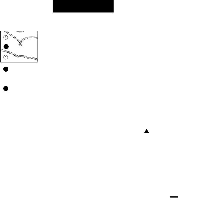
13.AVOID CONTINUOUS PULLS FROM EXTREME ANGLES as this will cause the wire rope to pile up at one end of the drum (Figure 7). This can jam the wire rope in the winch, causing damage to the rope or the winch.
G E N E R A L S A F E T Y I N F O R M AT I O N
( C O N T. )
14.NEVER OBSCURE THE WARNING INSTRUCTION LABELS.
15.Always operate winch with an unobstructed view of the winching operation.
16.Equipment such as tackle, hooks, pulley blocks, straps, etc. should be sized to the winching task and should be periodically inspected for damage that could reduce their strength.
17.NEVER RELEASE FREESPOOL CLUTCH WHEN THERE IS A LOAD ON THE WINCH.
18.STORE THE REMOTE PENDANT ASSEMBLY IN A SAFE PLACE when not in use to prevent use by children or other unauthorized persons.
19.DO NOT OPERATE WINCH WHEN UNDER THE INFLUENCE OF DRUGS, ALCOHOL OR MEDICATION.
20.ALWAYS UNPLUG THE REMOTE PENDANT BEFORE WORKING IN OR AROUND THE FAIRLEAD OR WINCH DRUM (THE DANGER ZONE) so that the winch cannot be turned on accidentally.
21.When moving a load, slowly take up the wire rope slack until it becomes taut. Stop, recheck all winching connections. Be sure the hook is properly seated. If a nylon sling is used, check the attachment to the load.
22.When using your winch to move a load, place the vehicle transmission in neutral, set vehicle parking brake and chock all wheels.
23.DO NOT USE THE WINCH TO HOLD LOADS IN PLACE.
Use other means of securing
loads such as tie down straps. Superwinch offers a
wide variety of tie downs. Contact your local Superwinch dealer.
24.USE ONLY FACTORY APPROVED SWITCHES, REMOTE CONTROLS AND ACCESSORIES. Use of nonfactory approved components may cause injury or property damage and could void your warranty.
25.DO NOT MACHINE OR WELD ANY PART OF THE WINCH. Such alterations may weaken the structural integrity of the winch and could void your warranty.
26.Do not power the winch out for more than 50 feet (15.2m) or longer than 2 minutes.
! |
WARNING |
The drum |
and wire rope |
may get very hot (Figure 8).
27.DO NOT CONNECT WINCH TO EITHER 110V AC HOUSE CURRENT OR 220V MAINS AS WINCH BURNOUT OR FATAL SHOCK MAY OCCUR!
28.Never allow shock loads to be applied to winch or wire rope.
29.Use caution when pulling or lowering a load up and down a ramp or incline. Keep people, pets and property clear of the path of the load.
HOT!
Figure 8
9

N M O U T I N G
U Y O R W I N C H
Superwinch mounting (fitting) kits are available for most popular vehicles. If you can‘t locate a kit locally
contac |
t Superwinch at the address |
elist |
d on theo fr nt of this manual |
for the name of a Superwinch dealer near you.
Detailed Mountingu instr ctions are provided with each mounting kit. Read and follow directi ons careful ly to ensureo pr per winch alignment ando tr uble fr ei operat on.
This winch
! WARNING MUST be mounted with the wire rope in thee und r- wind direction. Impropert moun ing
lcou d damage your winch and void your warranty.
DRUM SUPPORT
PLATE SCREWS
6.0
(152)
ROLLER FAIRLEAD
SCREWS
Figure 9
1.
(31
3.
(93.
5.9
(150) 
NOTES
1. All dimensionsr a e in inches [millimeters].
I N S TA L L AT I O N
MINIMUM ELECTRI AL REQUIREMENTS
For 12 volt winches, a 60 ampere alterna tor and battery with 440 cold-crankingp am eres capacity are the minimum recommended power esourc s. If the winch is in heavy use, ani aux liarye batt ry and heavy duty alternator are recommended.
Step (1)
Insta ll mounting kit or st uctural support for winch.
Step (2)
When mounting the winch, pull the
e fr espool clutch lever into the freespool position. Unwind 25-30 feet of rope
o fr m the. drum This will provide the access eneed d toa inst ll the mounting boltsoint the base plate mounting holes. Mount the winch to the mount that you have designed. Mounting bolts
supplied are the correct length for use with up to a 1/4”(6.3 mm)
thick plate.
MOTOR
SCREWS
DRUM SUPPORT
PLATE
2. Typical mount is to flat surface capable of handling the loads. Bolts to be Grade 5 or better.
I N S TA L L AT I O N
C O N T.
|
Do not sub- |
|
! WARNING |
||
stitute any |
strength grade weaker than grade 5.
When attaching wires to the motor terminals and solenoid (relay), hold the inner nut when tightening the outer nut. Do not allow the motor terminals to rotate for it may cause
rinte nal wirer b eakage or part misalignment. Be especially careful in
r p eventing the solenoid (relay) terminalsrf om rotating. Any rotation can damage the solenoid (see Figure 10).
Figure 10
Step (3)
Disconnect the vehicl etbat ery leads.
! DANGER Automobile batteries
contain gasses whichr a e flammable and explosive. Wear eyer p otection during installation and remove all metaly jewelr . Do not lean over battery while making connections.
Be Prepared
Figure 11
Step (4)
Route the two (2) wires through the vehicle grille toy the batter . To ensure against insulation abrasion and/or cutting, apply several layers of electrical tape where wiring may come in contact with sharp metal parts of the vehicle. Attach the circuit breaker assembly to the end of the red wire. Wrap the circuit
breaker assembly with electrical tape to prevent accidental short circuits. Attach other end of circuit breaker assembly to battery positive terminal.
10 |
11 |

I N S T A L L A T I O N
C O N T.
Note: If you choose to locate the winch at a greater distance than the wires provided will permit,
it may be necessary to purchase a larger gauge wire to get the
best performance from your winch. If the total length of additional wire to be added to the system exceeds 10' (3m), use a larger wire gauge size.
Attach the circuit breaker directly to the battery positive terminal, and reattach the terminal to the battery. If your vehicle is equipped with side pole terminals, it may be necessary to obtain auxiliary side terminal bolts from your localauto parts dealer to make these connections.
Connect the remaining wire to the battery negative terminal, and connect the terminal to the battery.
Step (5)
Lift the freespool clutch lever to the “Free” position. Pull several feet of wire rope off the drum. Return the clutch lever back to the “Engaged” position. Plug in the remote pendant control. Press the switch trigger to the “RopeOut” position momentarily to check wire rope drum rotation and direction. If the drum rotates in the wrong direction, recheck your wiring. The Handheld pendant switch activates a solenoid that activates power to the winch motor. One solenoid is for “Rope Out” motor direction and the other is for the “Rope In” motor direction (Fig. 12).
To prevent
! CAUTION unauthorized use of the winch, remove pendant control and store in a clean dry area such as the glove box.
A |
B |
Cable Out |
Cable In |
Figure
PENDANT OPERATION
The handheld pendant switch activates a solenoid that activates power to the winch motor. To connect the pendant control, remove the cover on the plug receptacle (Figure 13) and insert the plug end of remote switch. The plug on the pendant control cord is keyed and will fit into the socket only one way. The switch trigger
returns to the “Off” position when released. To change direction, move the toggle in the other direction. (Fig.12)
! |
CAUTION |
The switch |
|
assembly must |
|||
|
|
be kept free of dirt and moisture to ensure safe operation.
Figure 13

 DUST
DUST
COVER
PULLING OUT THE WIRE ROPE
The wire rope has been installed on your winch under minimal load at the factory. The wire rope must be respooled onto the drum under load so that the outer layers will not draw down into the inner ones, thereby damaging the wire rope.
Lift the clutch lever to the “Free” position as shown in Figure 13. If there is a load on the wire rope, the clutch lever may not turn easily. DO NOT FORCE THE CLUTCH LEVER. Release tension on the wire rope by jogging out some of the wire rope. Releasing the clutch and pull out the wire rope and secure to anchor or load. Check that there are at least five (5) turns of wire rope left on the drum. Re-engage the drum by returning the clutch lever to the “Engaged” position (see Figure 14).
Lever must
! CAUTION be in the
“Engaged” position and locked before winching.
FREE
ENGAGED
Figure 14
TIPS FOR EXTENDING THE LIFE OF YOUR WINCH
1.KEEP THE WIRE ROPE TIGHTLY WOUND ON THE DRUM. Do not allow the wire rope to become loosely wound. A loosely-wound spool allows a wire rope under load to work its way down into the layers of wire rope on the drum. When this happens, the wire rope may become wedged within the body of the windings damaging the wire rope. To prevent this problem, keep the wire rope tightly and evenly wound on the drum at all times. A good practice is to rewind the wire rope under tension after each use. One way to do this is to attach the hook to a stationary object at the top of a gradual incline and winch your vehicle up the incline.
2.DO NOT ALLOW WINCH MOTOR TO OVERHEAT. Remember, the winch is for intermittent use only. During long or heavy pulls the motor will get hot. For pulling
at rated capacity, allow motor to cool after 20 seconds of “On” time. At loads less than 50% of
rated capacity, allow to cool after 2 minutes of “On” time. KEEP THE ENGINE RUNNING TO RECHARGE THE BATTERY during this break.
3.USE A PULLEY BLOCK FOR HEAVY LOADS. To maximize winch and wire rope life, use a pulley block to double line heavier loads (Figure 15).
Figure 15
12 |
13 |
4.The pull required to start a load moving is often much greater than the pull required to keep it moving. AVOID FREQUENT STOPS AND STARTS during pull.
5.PREVENT KINKS BEFORE THEY OCCUR.
a
b
c
Figure 16
a.This is the start of a kink. At this time, the wire rope should be straightened.
b.The wire rope was pulled and the loop has tightened to a kink. The wire rope is now permanently damaged and must be replaced.
c.Kinking causes the wire strands under the greatest tension to break and thus reduces the load capacity of the wire rope. The wire rope must be replaced.
6.EQUIPPING THE WINCH WITH A ROLLER FAIRLEAD will substantially reduce wear on the wire rope during angle pulls (Figure 17). The rollers eliminate heavy rubbing and abrasion to the wire rope.
Figure 17
14
M A I N T E N A N C E
A N D R E PA I R S
Periodically check tightness of mounting bolts and electrical connections. Remove any dirt or corrosion that may have accumulated on the electrical connections.
Repair should be done by Authorized Superwinch Repair Centers ONLY. Do not attempt to disassemble the gearbox. Disassembly will void warranty.
LUBRICATION
The gearbox and drum bearing are permanently lubricated with a high performance gear lube. If relubrication is necessary (after repair or disassembly) only use Shell Alvenia EP2 or equivalent.
REPLACING THE WIRE ROPE
Figure 18
Never substitute a heavier or lighter wire rope. Never use rope made of any material other than wire.
Always replace damaged wire rope with manufacturer’s identical replacement part (see Replacement Parts list). Pass attaching end of wire rope through the fairlead (if equipped) and attach it to the drum. When inserting the wire rope into the drum, insert it into the correct end of the hole provided (Figure 18). Tighten the set screw securely.
It is important that the wire rope be wound tightly onto the drum. A good way to do this is to attach the wire rope hook to a fixed object at the top of a slight incline, then winch the vehicle up the incline.
BRAKE OPERATION
Your S Series winch has a wrap spring brake that stops and holds loads up to 50% rated capacity on the first layer of wire rope closest to drum.
Each additional layer of wire rope reduces brake capacity approximately 10%. When powering the winch in, the brake is disengaged and does not become activated until the motor is turned off and the load tries to pull the wire rope off the drum. When the winch is powered out, as in releasing a load, the brake is engaged and the motor must over power the brake drag to rotate the drum. Therefore, it is normal for the winch to operate faster in one direction than the other. The brake is designed for the wire rope to be used in the underwind position only. DO NOT OVERWIND. Powering against the brake will cause heat to build up in the drum and may transfer heat to the wire rope (Figure 19). DO NOT POWER OUT FOR MORE THAN 50 FEET (15.2m) OR 2 MINUTES.
! WARNING |
The drum and |
|
wire rope may |
|
|
|
get very hot. |
When wire rope is removed from the drum, as in bringing the hook to the load, the freewheel feature of the winch should be used.
HOT!
Figure 19
15

CW I N HB A S S E M LY
52 |
Safety |
|
30
R E P L A C E M E T
PA R T S L I S T
|
|
|
|
|
|
Reference |
|
|
|
|
|
|
|
|
|
|
|
Number |
Description |
|
Part Number |
Qty |
|
1 |
Base |
|
89-52021 |
1 |
|
||||||
2 |
Groove Pin |
|
89-23303-01 |
2 |
|
||||||
3 |
Cable Guard |
|
89-32268 |
1 |
|
||||||
4 |
Main Bearing |
|
89-22268 |
1 |
|
||||||
|
5 |
M6 x 1 x 8mm Cup Pt. Set Screw |
2 |
90-23164-1 |
1 |
|
|||||
7 |
Drum Bearing |
|
89-22269 |
1 |
|
||||||
8 |
Drum Support |
|
89-40092 |
1 |
|
||||||
9 |
Thrust Washer |
|
90-12574 |
2 |
|
||||||
|
10 |
Drive Plate |
|
89-32263 |
1 |
|
|||||
11 |
Rotating Ring Gear |
|
89-32265 |
1 |
|
||||||
12 |
Planetary Carrier Assembly |
|
89-22141 |
1 |
|
||||||
14 |
Sun Gear |
|
89-33303 |
1 |
|
||||||
15 |
Stationary Ring Gear |
|
89-32266 |
1 |
|
||||||
16 |
Free Wheel Repair Kit |
|
89-10580 |
1 |
|
||||||
|
|
|
|
|
|
|
(Includes Shaft,r Leve , Handle, and Rivet) |
|
|
|
|
17 |
Free Wheel Spring |
|
90-23152-08 |
1 |
|
||||||
18 |
M6 x 1 x 16mm Flat Head Screw |
1 |
89-22291-0 |
4 |
|
||||||
20 |
Housing Assembly (includes 21 & 22) |
4 |
89-4010 |
1 |
|
||||||
21 |
Needle Bearing (.8125 x 1.125 x .750) |
3 |
89-23263-0 |
1 |
|
||||||
|
22 |
Motor Shaft Bearing |
|
89-12002 |
1 |
|
|||||
23 |
S5000 Logo |
|
89-17332 |
1 |
|
||||||
|
|
|
|
|
|
|
S4000 Logo |
|
89-17331 |
1 |
|
27 |
M6 x 1 x 13mm Button Head Screw |
|
89-22290-01 |
2 |
|
||||||
29 |
Cable Tension Spring |
|
89-32295 |
1 |
|
||||||
|
30 |
Handsaver |
|
87-31120 |
1 |
|
|||||
13 |
Wire Rope Assembly w/hook 1/4"x50' (S5000) |
1577A |
1 |
|
|||||||
|
|
|
|
|
|
|
Wire Rope Assembly w/hook 7/32"x60' (S4000) |
1514A |
1 |
|
|
23 |
M6 x 1 x 16mm Button Head Screw |
2 |
89-22290-0 |
5 |
|
||||||
33 |
12 Volt Complete Motor (S5000) |
4 |
90-3329 |
1 |
|
||||||
|
|
|
|
|
|
|
24 Volt Complete Motor |
|
89-33298 |
1 |
|
|
|
|
|
|
|
|
12 Volt Complete Motor (S4000) |
5 |
90-3329 |
1 |
|
|
|
|
|
|
|
|
24 Volt Complete Motor |
|
90-33318 |
1 |
|
37 |
Motor Cover |
|
89-52024 |
1 |
|
||||||
38 |
Superwinch“ ” Nameplate |
|
89-22277 |
1 |
|
||||||
93 |
M4 x 0.7 x 6mm Hex Washer Head Screw |
|
89-22292-01 |
4 |
|
||||||
42 |
Drum |
|
89-40085 |
1 |
|
||||||
|
43 |
Brake Spring |
|
89-22342 |
1 |
|
|||||
44 |
Brake Adapter |
|
89-22287 |
1 |
|
||||||
45 |
Roller Fairlead |
|
2235 |
1 |
|
||||||
|
|
|
|
|
|
|
|
|
|
|
|
|
|
49 |
5/8 x 2.352 Roller |
|
90-12568-04 |
2 |
|
||||
|
|
|
|||||||||
|
|
|
|
50 |
5/8 x 4.735 Roller |
|
90-12568-06 |
2 |
|
||
|
|
|
|
51 |
Roller Fairlead Shaft (Short) |
|
89-22334-01 |
2 |
|
||
|
|
|
52 |
Safety Label |
|
89-20330 |
1 |
|
|||
|
|
|
|
|
|||||||
|
|
|
|
||||||||
|
|
|
|
|
|
|
|
|
|
|
|
|
|
|
|
|
|
|
|
|
|
|
|
16 |
17 |

|
S O L E N O I D A S S E M B LY |
|
|
|
R E P L A C E M E N T |
|
|
|
|||||||||||||||||
|
|
|
|
|
|
|
|
|
|
|
|
|
|
|
|
|
|
|
|
|
|
PA R T S L I S T |
|
|
|
|
|
|
|
|
|
|
|
|
|
|
|
|
|
|
|
|
|
|
|
|
|
|
|
|
|
|
|
|
|
|
|
|
|
|
|
|
|
|
|
|
|
|
|
|
|
|
|
|
|||
|
|
|
|
|
|
|
|
|
|
|
|
|
|
|
|
|
|
|
|
Reference |
|
|
|||
|
|
|
|
|
|
|
|
|
|
|
|
|
|
|
|
|
|
|
|
Number |
Description |
Part Number |
Qty |
||
|
|
|
|
|
|
|
|
|
|
|
|
|
|
|
|
|
|
|
|
|
|
|
|
|
|
|
|
|
|
|
|
|
|
|
|
|
|
58 |
|
|
|
|
53 |
|
Leadwire spacer kit |
89-24430 |
1 |
||||
|
|
|
|
|
|
|
|
|
|
|
|
|
|
|
|
|
|
|
|
||||||
|
|
|
|
|
|
|
|
|
|
|
|
|
|
|
|
|
|
|
54 |
|
Buss bar kit |
89-24431 |
1 |
||
|
|
|
|
|
|
|
|
|
|
|
|
|
|
|
|
|
|
|
55 |
|
Black 2 gage wire (-), S5000 12V |
89-22635-61 |
1 |
||
|
53 |
|
|
|
|
|
|
|
|
||||||||||||||||
|
|
|
|
|
|
|
|
|
|
|
|
|
|
|
|
|
|
|
|
|
|
Black 6 gage wire (-), S4000, S5000 24V |
89-23292-38 |
1 |
|
|
|
|
|
|
|
|
|
|
|
|
|
|
|
|
|
|
|
|
|
|
|
||||
|
|
|
|
|
|
|
|
|
54 |
|
|
|
|
|
|
|
|
|
|
|
|
||||
|
|
|
|
|
|
|
|
|
|
|
|
|
|
|
|
|
|
|
|
|
|||||
|
|
|
|
|
|
|
|
|
|
|
|
|
|
|
|
57 |
|
Band clamp |
89-14459 |
2 |
|||||
|
62 |
|
|
|
|
|
|
|
|
|
|
|
|
|
|
|
|
|
|||||||
|
|
|
|
|
|
|
|
|
|
|
|
|
|
|
|
|
|
|
|||||||
|
|
|
|
|
|
|
|
|
|
|
|
|
|
|
|
|
|
|
58 |
|
Red 2 gage wire (+), S5000 12V |
89-22635-60 |
1 |
||
|
|
|
|
|
|
|
|
|
|
|
|
|
|
|
|
59 |
|
|
|
||||||
|
|
|
|
|
|
|
|
|
|
|
Red 6 gage wire (+), S4000, S5000 24V |
89-23292-37 |
1 |
||||||||||||
|
|
|
|
|
|
|
|
|
|
|
|
|
|
|
|
|
|
|
|
|
|
||||
|
|
|
|
|
|
|
|
|
|
|
|
|
|
|
|
|
|
|
59 |
|
Socket |
90-14140 |
1 |
||
|
|
|
|
|
|
|
|
|
|
|
|
|
|
|
|
|
|
|
60 |
|
Type 6 solenoid with bracket, 12V |
89-24429 |
1 |
||
|
|
63 |
|
|
|
|
|
|
|
|
|
|
|
|
|
|
|
Type 6 solenoid with bracket, 24V |
89-24467 |
1 |
|||||
|
|
|
|
|
|
|
|
|
|
|
|
|
|
|
|
|
|
|
|
|
|
||||
|
|
|
|
|
|
|
|
|
|
|
|
|
|
|
|
|
|
|
|
|
|
||||
|
|
|
|
|
|
|
|
|
|
|
|
|
|
|
|
|
|
|
|
|
|
|
|||
|
|
|
|
|
|
|
|
|
|
|
|
|
|
|
|
|
61 |
|
Handheld remote control |
90-33450-02 |
1 |
||||
|
55 |
|
|
|
|
|
|
|
|
|
|
|
|
||||||||||||
|
|
|
|
|
|
|
|
|
|
|
|
|
|
|
|
|
|
60 |
62 |
|
Ground jumper wire 18 gage |
89-23283 |
1 |
||
|
|
|
|
|
|
|
|||||||||||||||||||
|
|
|
|
|
|
|
|
|
|
|
|
|
|
|
|
|
|
|
63 |
|
Terminal adapter |
89-14458 |
1 |
||
|
|
|
|
|
|
|
|
|
|
|
|
|
|
|
|
|
|
|
|
|
|
|
|
|
|
61
TORQUE SPECIFICATIONS
|
TORQUE SPECIFICATIONS |
|
57 |
||
|
Drum Support Plate |
50-60 lb in |
|
||
|
Screws |
|
|
Hawse (Roller Fairlead) |
45-55 lb in |
|
Screws |
|
|
Base Screws |
65-75 lb in |
|
Motor |
35-40 lb in |
DRUM SUPPORT 
PLATE SCREWS
ROLLER FAIRLEAD |
|
|
|
|
|
MOTOR |
||
SCREWS |
|
|
|
|
|
SCREWS |
||
|
|
|
|
|
|
|
|
|
|
|
|
|
|
|
|
|
|
|
|
|
|
|
|
|
|
|
! |
WARNING |
Over torquing |
|
could damage |
|||
|
|
your winch and void your warranty.
DRUM SUPPORT  PLATE SCREWS
18 |
19 |
 Loading...