

Superwinch TALON SERIES WINCH Installation [en, es, fr]

INSTALLATION GUIDE
TALON SERIES
®
WINCH
+-
READ AND UNDERSTAND THIS MANUAL BEFORE
INSTALLATION AND OPERATION OF YOUR
SUPERWINCH.
Superwinch LLC.
359 Lake Road
Dayville, CT 06241, USA
tel: 1.800.323.2031
fax: 1.860.963.0811
info@superwinch.com
www.superwinch.com
90-14510 Rev B 8/21/11
Superwinch LTD.
Union Mine Road
Pitts Cleave
Tavistock, Devon
PL19 0NS, UK
tel: +44 (0) 1822 614101
fax: + 44 (0) 1822 615204
sales@superwinch.net
www.superwinch.com
1
SAFETY PRECAUTIONS
The responsibility for safe installation and operation of this winch ultimately rests with
you, the operator. Read and understand all safety precautions and operating instructions before installing and operating the winch. Careless winch operation can result
in serious injury and/or property damage. Never obscure or remove the warning or
instruction labels.
Throughout this manual, you will nd notations with the following headings:
(NOTES,
NOTAS)
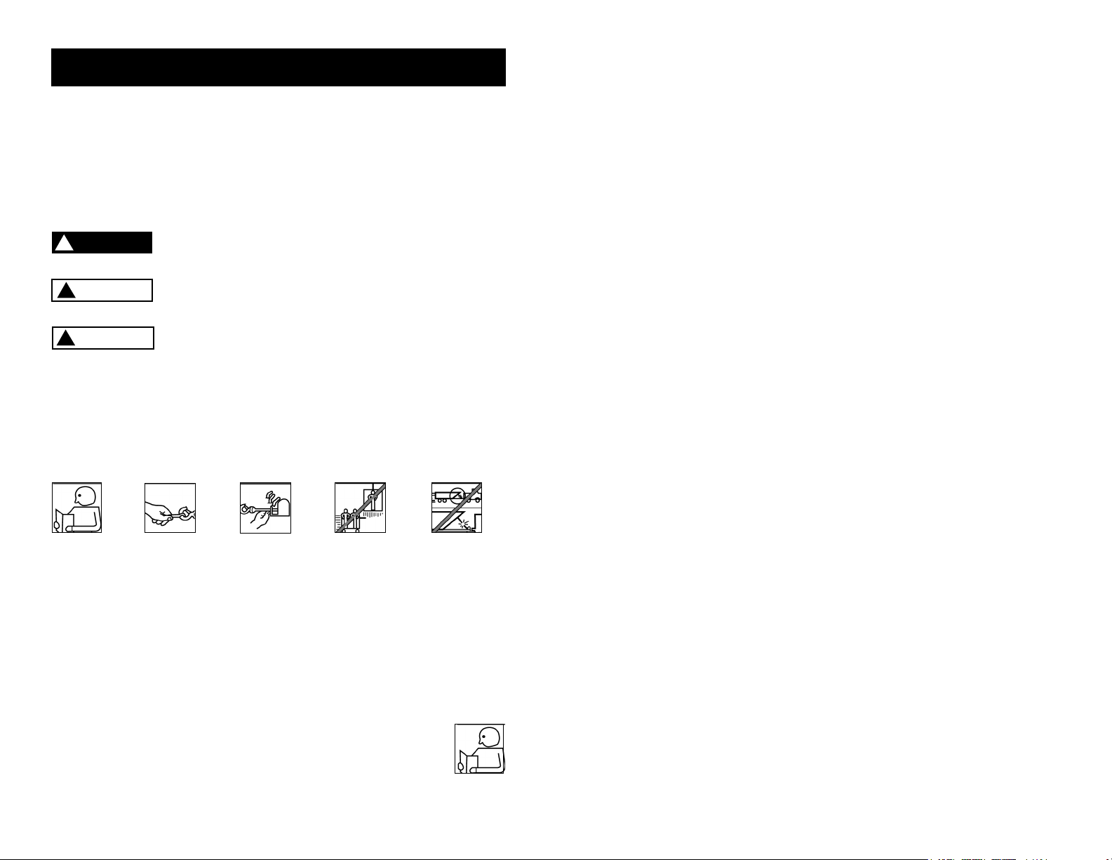
DANGER
!
WARNING
!
CAUTION
!
Indicates an imminently hazardous situation which, if not
avoided, will result in death or serious injury.
Indicates a potentially hazardous situation which, if not
avoided, could result in death or serious injury.
Indicates a potentially hazardous situation which, if not
avoided, may result in minor or moderate injury. This notation
is also used to alert against unsafe practices.
Note: Indicates additional information in the installation and operation procedures of
your winch.
The following symbols on the product and in the Owners manual are used:
Read Owner's
Manual
Always Use
Handsaver
Keep clear of winch,
rope and hook
while operating
Never use winch
to lift or move
people
Never use
winch to hold
loads in place
Correct installation of your winch is a requirement for proper operation.
Please Note: Winch is designed primarily for intermittent applications. This winch is not
designed to be used in industrial or hoisting applications and Superwinch does not
warrant it to be suitable for such use. Superwinch manufactures a separate line of
winches for industrial/commercial use. Please contact Customer Service Department
for further information.
Congratulations on you choice!
AFTER READING AND UNDERSTANDING THIS MANUAL, LEARN TO USE
YOUR WINCH. After installing the winch, practice using it so you will be
familiar with it when the need arises.
2
27
(NOTES,
NOTAS)
MOUNTING YOUR WINCH
MOUNTING KITS
SUPERWINCH RECOMMENDS THE USE OF A MOUNT KIT FOR SECURE MOUNTING TO
YOUR VEHICLE. For information on available kits, contact your Superwinch product
dealer or go to www.superwinch.com for the most current list of kits.
If you choose not to purchase a mounting kit, your Superwinch needs to be attached
to a secure and at mounting location. Note that your winch may not be able to be
operated safely without some equipment included in the kit. If you choose not to
purchase a mounting kit, contact Superwinch for recommended accessories and the
name of a dealer near you.
Detailed mounting instructions for your specic vehicle are provided with each mounting kit. Read and follow directions carefully.
D R
CAUTION
!
and void your warranty.
!
Fig. 1
Note: Your winch is designed to ROPE IN and ROPE OUT in one direction. Do not at-
tempt to reverse the operation of your winch.
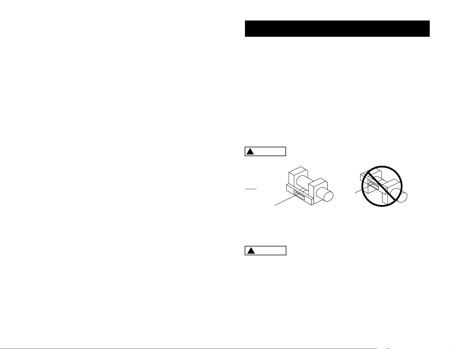
Do not mount winch inverted (base upward) or put the
CAUTION
!
winch mounting hardware in direct tension condition. In all
installations, the unit must be mounted so the rope feeds through the hawse or
roller fairlead on the front of the winch and does not rub across housings.
For winch capacities, a complete parts list, and an exploded diagram of your specic
Superwinch, refer to the Technical Data Sheet included in this package.
For instructions on safe winch operation and tips for prolonging the life of your winch,
refer to the User’s Guide included in this package.
This winch must be mounted with the rope in the under wound
direction ( Fig. 1 ) Improper mounting could damage your winch
Underwind
Overwind
26
3
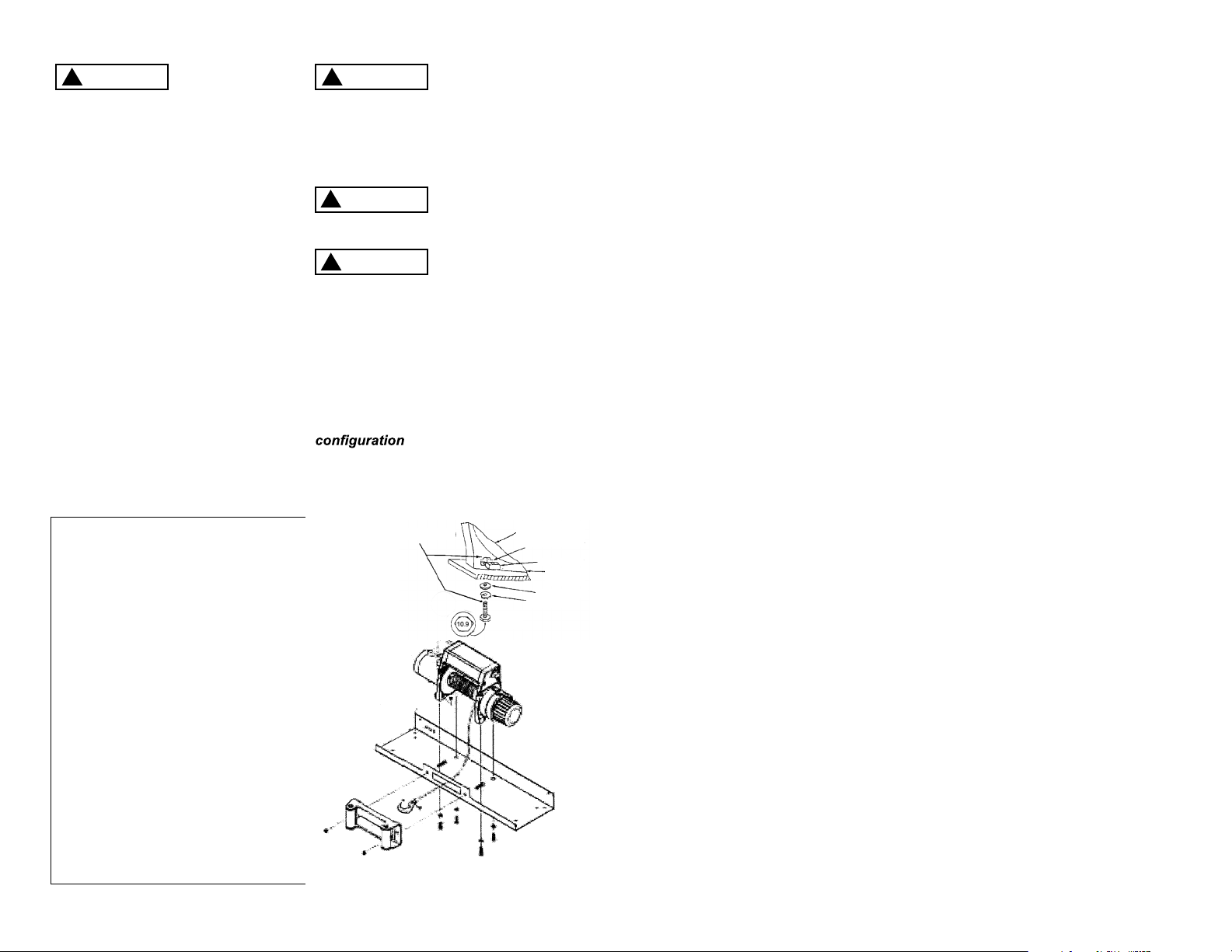
Improper mounting
WARNING
!
can cause personal
!
injury. Improper mounting could
damage your winch and void the warranty.
MINIMUM ELECTRICAL REQUIREMENTS
A 60 amp. alternator and battery with
440 cold-cranking amperes capacity
are the minimum recommended power
sources. If the winch is in heavy use, an
auxiliary battery is recommended.
Under some circumstances, it may be
appropriate to install additional circuit
protection devices (circuit breakers). If
in
doubt, seek appropriate advice.
Superwinch recommends that all winch
electrical systems can be readily and
quickly isolated from their electrical supply in the event of an emergency. The
winch electrical’s system should always
be isolated when the winch is not in use.
1. Install mounting kit or structural sup-
port for the winch.
2. Mount the winch to a mounting plate
or to a mount that you have properly
designed.
If not using a Superwinch mounting
accessory, follow the general
guidelines listed below.
For 9.5 and 12.5 models:
Mounting plate must be minimum 1/4”
(6.3mm) thick. Mounting bolt threads must
fully engage nut, but bolt must not contact
opposite side of nut pocket in casting. All 4
mounting bolts must be used to secure the
winch.
(see Fig 2 insert)
Your winch is a very
WARNING
!
!
powerful machine.
(NOTES,
NOTAS)
To protect yourself and property, the
winch must be properly mounted to a
structural support capable of withstanding the high pulling capacity of
the winch.
Do not substitute
WARNING
!
!
any strength grade
weaker than SAE Grade 8 (ISO 10.9).
CAUTION
!
When mounting
- forward position, the solenoid pack
can be rotated to be on top of the
motor or can be remote-mounted. To
rotate the solenoid box, remove the
two motor screws and solenoid box
bracket screws. Rotate the motor and
solenoid box upwards and reinstall
the screws. If remote mounting, the
solenoid pack may be mounted in any
EXCEPT inverted
(i.e. solenoid studs facing down).
Inverted mounting may cause erratic
operation. Use properly sized wire or
contact Superwinch for remote mount
kit options.
M
(Must not touch)
Bolt
Support Casting
Mounting Pocket
Nut
Mounting Plate
Flat Washer
Lock Washer
For 14.0 and 18.0 models:
Mounting hardware suppied with winch is
sized for a 5/16” (8mm) thick mounting plate.
For thicker mounting plates, minimum 18mm
(0.700”) bolt engagement in casting is
required. Bolts must not bottom out in the
tapped holes before being fully tightened. All
8 mounting bolts should be used when
possible. Minimum of 4 bolts required.
6.5” x 10” (165.1mm x 254mm) pattered is prefered
4.5“ x 10” (114.3mm x 254mm) pattern is acceptable.
4
INSTALLATION
Figure 2
25
Treuil de la Série Talon
LE POUVOIR
ROUGE + 12V DC 2 AWG
ROUGE DE
DOUILLE
T E L E G R A P H I E R D I A G R A M
DOUILLE
ROUGE
LE SOL
24
Bleve
JAUNE
NEGATIF
PILE
POSITIF
SOL NOIR 2AWG
LA VIS DE SOL
DE MOTEUR
DE TREUIL
LE SOL NOIR
DE SOLENOIDE
LE SOL
NOIR DE
DOUILLE
)
Bleve
Contrôle de poche :
Noir-à-le jaune = EN
(LED rouge sur
Noir-à-le marron = HORS
(LED verte sur
2AWG
TRANSPORTE LA BARRE
If different length
WARNING
!
!
bolts, nuts, washers
and other hardware are required for
your installation, always use hardware that equals or exceeds the
PENDANT OPERATION
OPERATION
Rope
Out
Rope
In
strength grade of the supplied hardware. In no circumstance should the
end of the mounting bolts touch the
inside of the casting mount pockets.
DANGE
Figure 3
WARNING
!
!
which are and explosive.
Wear eye protection during installation and remove all metal jewelry.
Do not lean over battery while making connections.
Automobile batteries
contain gasses
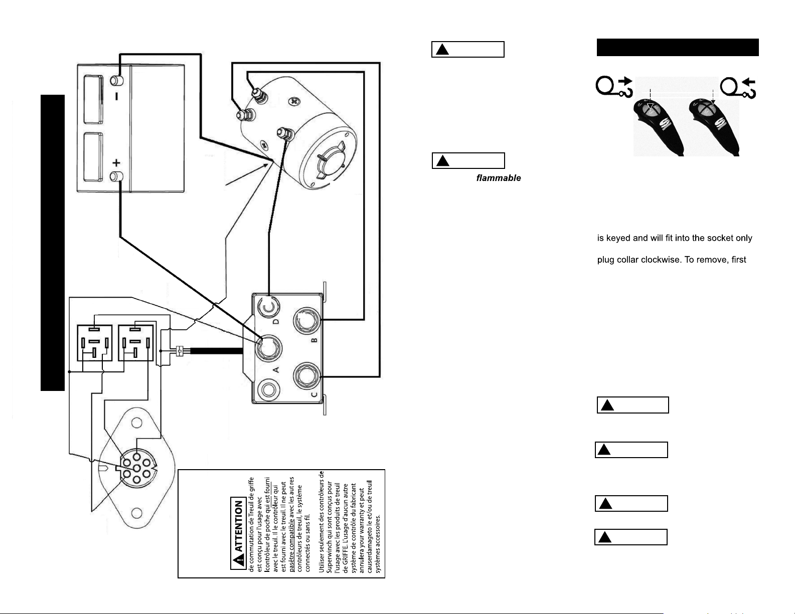
The handheld pendant switch activates
a solenoid that activates power to the
winch motor.
To connect pendant control, remove the
cover on the plug receptacle and insert
the plug end of the remote switch.
The plug on the pendant control cord
3. Disconnect the vehicle negative and
positive battery leads. Route the long
one way. Lock the plug by rotating the
red and black color coded wires to the
battery. To ensure against insulation
abrasion and/or cutting, apply several
D
2AWG
TRANSPORTE LA BARRE
layers of electrical tape where wiring
may come in contact with sharp parts
on the vehicle. Attach the red color
coded wire to the battery positive and
2AWG
TRANSPORTE LA BARRE
reattach the terminal to the battery.
If your vehicle is equipped with side
pole terminals, it may be necessary
to obtain auxiliary side terminal bolts
from your local auto parts dealer to
make these connections.
Connect the black color coded wire to
the battery negative terminal, then
connect the terminal to the battery.
4.
Pull and turn the freespool clutch lever
to the, “disengaged” position. Pull sev-
eral feet of wire rope off the drum.
Return the clutch lever back to the,
“engaged” position. Plug in remote
pendant control. Push button momen tarily to check rope drum rotation
direction. If drum rotates in the wrong
direction, recheck your wiring.
unlock the plug by rotating collar in the
opposite direction. The switch returns
to the “off” position when released. To
change direction, press the button for
the other direction.
PENDANT BATTERY INSTALLATION
!
To install the AAA batteries into the handheld pendant, remove the battery door
on the back of the pendant and insert the
batteries as noted on the graphic inside
the battery compartment. Replace the
battery door.
The switch assem-
CAUTION
!
free of dirt and moisture to ensure
safe operation.
W
ARNING
!
break before the
winch stalls. For heavy loads use a
pulley block to reduce the load on
the wire rope.
If the winch motor
CAUTION
!
stalls, do not con-
tinue to apply power to the winch.
CAUTION
!
orized use of
To prevent unauth-
the
winch, remove the pendant control
and store it in a clean dry area such
as the glove box.
5
 Loading...