

S101622 Rev. 1 superwinch.com | info@superwinch.com 1
User’s Manual
SI Series, Hydraulic 8,000 & 10,000
Safety Precautions

S101622 Rev. 1 superwinch.com | info@superwinch.com 2
READ AND UNDERSTAND THIS MANUAL BEFORE INSTALLATION AND
OPERATION OF YOUR SUPERWINCH
Table of Contents
1 INTRODUCTION
2 GENERAL SPECIFICATION DATA
INSTALLATION
3 HYDRAULIC SYSTEM
4 WINCH
5 ROPE
COMMISSIONING AND USE
6 FREESPOOL USE
7 TIPS FOR EXTENDING THE LIFE OF YOUR WINCH
MAINTENANCE
8 RUNNING IN, MAINTENANCE & SERVICING
9 HYDRAULIC SYSTEM TROUBLESHOOTING
PARTS
10 ACCESSORIES
11 WARRANTY
S101622 Rev. 1 superwinch.com | info@superwinch.com 3
1. INTRODUCTION
From all of us at Superwinch, “thank you.” We’ve built this winch to perform and
we’ve built this manual to help you get the most from your Superwinch.
Please read and understand this owner’s manual before installing your SI Series winch. You
industrial winch is a very powerful machine. If used unsafely or improperly, there is a possibility
that property damage or personal injury can result. We have included several unique features in
the Hydraulic Industrial winch to minimize this possibility; however, your safety ultimately
depends on your caution when using the product.
Pay particular attention to the caution notes preceded with the symbol shown here. The notes
contain advice for your safety and protection.
Please Note: The Superwinch SI Series winches are designed for total reliability. This winch is not
designed to be used in hoisting applications and Superwinch does not warrant it to be suitable
for such use.
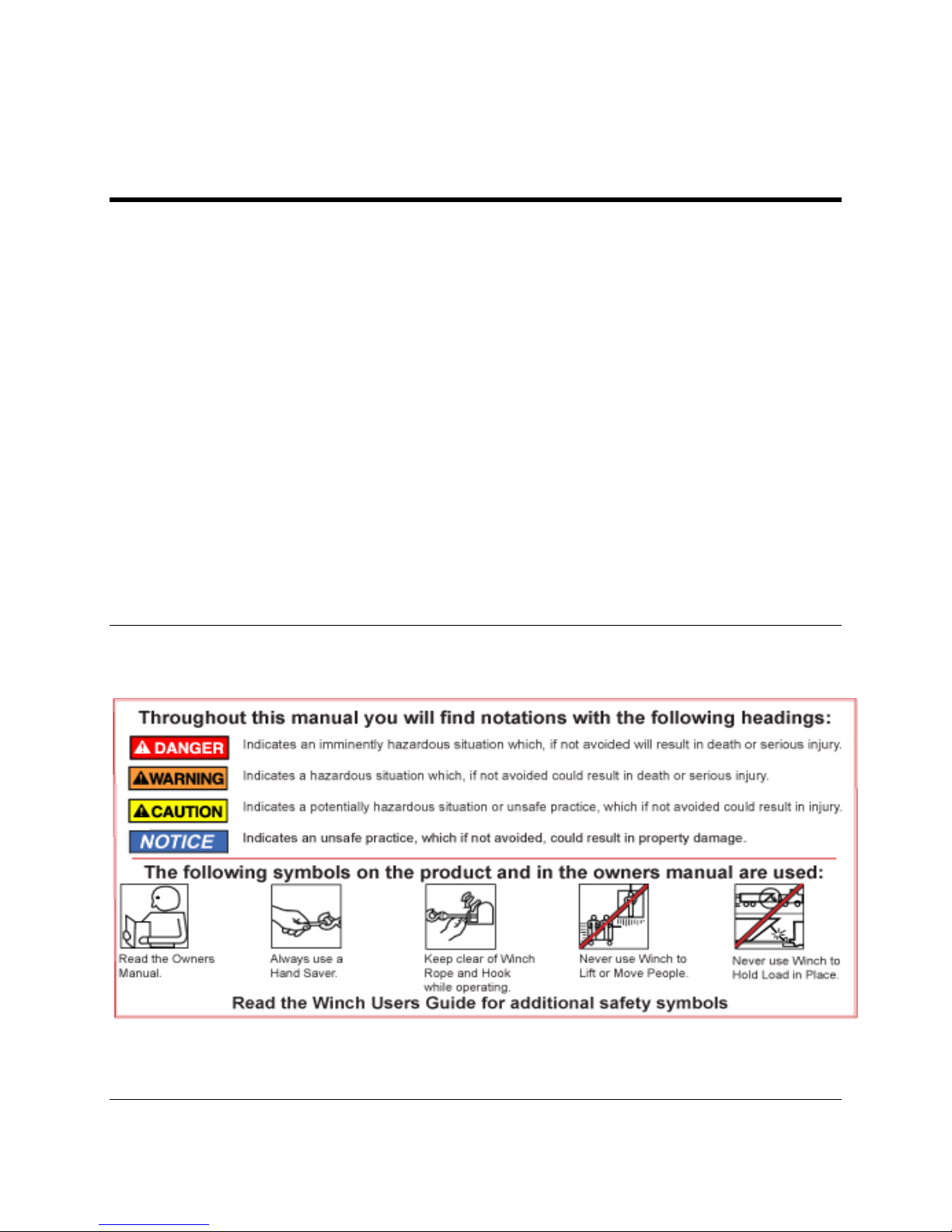
WARNING, CAUTIONS AND NOTES
These warnings, cautions and notes are given throughout these instructions in the following
forms:
REPAIRS AND REPLACEMENTS
S101622 Rev. 1 superwinch.com | info@superwinch.com 4
Before contacting Superwinch or your nearest authorized Superwinch dealer, please have the
following information:
Part Number:
Serial Number of the Winch:
POISONOUS SUBSTANCES
Many liquids and other substances used should under no
circumstances be consumed, and should be kept away from
open wounds. These substances include (among others)
hydraulic oil.
SYNTHETIC RUBBER
Many ‘O’ ring seals, flexible pipes and similar items, when
subjected to fire or heat can become highly corrosive. Handle
with seamless industrial gloves only. Should skin contact occur,
remove contaminated clothing immediately and obtain medical assistance without delay.
RECYCLING AND THE ENVIROMENT
It is illegal to dispose of used oil in the ground, down sewers or
drains, or into waterways.
Dispose of used oil through an authorized waste disposal
contractor or recycling center. If in doubt contact your local authority for advice on how to
dispose of the oil or disposal facilities.

S101622 Rev. 1 superwinch.com | info@superwinch.com 5
2. GENERAL SPECIFICATION DATA
Type: Hydraulic Industrial
Gear Reduction: Planetary
Gear Ratio: 16:1
Drum: Steel Drum
Braking: Integral bi-directional, full load holding, hydraulically released,
spring applied brake.
Load Control: Optional Superblock Load Control Valve provides dynamic brake to
give a controlled stop on winch-out, under load. Brake opening
also assisted by Superblock.
Freespool: Operated either by an ergonomically designed handle, a cable
system, or by integral pneumatic device. Can be mounted to winch
side or top.
Mounting: Designed to meet most industry standard dimensions, 4 ½” x 10”
(254mm x 114.3mm). See 4) Winch Installation section of this
manual for more information.
STANDARD DRUM MODELS
Model Designation
SI- 8K Hyd.
SI- 10K Hyd.
Part Number
S100419
S100420
Weight (Less Rope)
107 lbs. / 48.5 kg
109 lbs. / 49.4 kg
Recommended Rope Diameter
3/8" / 9.5mm
3/8" / 9.5mm
Drum Capacity
169' / 51.5m
169' / 51.5m
Drum Diameter
3.5"/ 88.9mm
3.5"/ 88.9mm
Line Speed (1st Layer, No Load)
52 FPM / 15.8 MPM
31.5 FPM/ 9.6 MPM
Line Pull (Bottom Layer)
8,000 lbs. / 3628 kg.
10,000 lbs. / 4536 kg.
Operating Pressure
2200 PSI / 152 Bar
2050 PSI / 141 Bar
Oil Flow
15 GPM / 56.8 LPM
15 GPM / 56.8 LPM
LONG DRUM MODELS
Model Designation
SI- 8K Hyd.
SI- 10K Hyd.
Part Number
S100425
S100426
Weight (Less Rope)
111 lbs. / 50.3 kg
113 lbs. / 51.3 kg
Recommended Rope Diameter
3/8" / 9.5mm
3/8" / 9.5mm
Drum Capacity
202' / 61.5m
202' / 61.5m
Drum Diameter
3.5"/ 88.9mm
3.5"/ 88.9mm
Line Speed (1st Layer, No Load)
52 FPM / 15.8 MPM
31.5 FPM/ 9.6 MPM

S101622 Rev. 1 superwinch.com | info@superwinch.com 6
Line Pull (Bottom Layer)
8,000 lbs. / 3628 kg.
10,000 lbs. / 4536 kg.
Operating Pressure
2200 PSI / 152 Bar
2050 PSI / 141 Bar
Oil Flow
15 GPM / 56.8 LPM
15 GPM / 56.8 LPM
SHORT DRUM MODELS
Model Designation
SI- 8K Hyd.
SI- 10K Hyd.
Part Number
S100422
S100423
Weight (Less Rope)
105 lbs. / 47.6 kg
107 lbs. / 48.5 kg
Recommended Rope Diameter
3/8" / 9.5mm
3/8" / 9.5mm
Drum Capacity
135' / 41.1m
135' / 41.1m
Drum Diameter
3.5"/ 88.9mm
3.5"/ 88.9mm
Line Speed (1st Layer, No Load)
52 FPM / 15.8 MPM
31.5 FPM/ 9.6 MPM
Line Pull (Bottom Layer)
8,000 lbs. / 3628 kg.
10,000 lbs. / 4536 kg.
Operating Pressure
2200 PSI / 152 Bar
2050 PSI / 141 Bar
Oil Flow
15 GPM / 56.8 LPM
15 GPM / 56.8 LPM
HYDRAULIC SYSTEM RECOMMENDATIONS
Note: These parts are listed as minimum expectations for the Superwinch SI Series to perform to
its fullest.
System Type Open system with filtered return line
Relief Valve Set at winch operating pressure
Pump A max oil supply of 15 gallons per minute (57 Liters/ per minute) at top
motor RPM. The pump must be capable of delivering a pressure of 2320
PSI or 160 bar.
Reservoir Must be fitted with an oil filler device comprising of a strainer, an air filter,
and a dip stick. The capacity of the tank should be at least 15.8 gal (60 L).
Note: Do not fill the tank to the top, since there must be space for
expansion in the tank. Suitable hydraulic oil is Castrol CRML or
equivalent. Typical viscosity rating of 150 – 175 CST at 100 degrees C
Hoses Hoses should have a working pressure of 2900 psi (200 bar) or greater.
Pressure and flow loss is increased as hose length increases and/or bore
sizes decreases. Pressure and return lines in excess of 11.5 ft. (3.5 m)
should be compensated with an increase in nominal bore size.
Control Valve 4- way, 3- position self-centering with ports A & B to tank in the neutral
position and built in relief valve. The relief valve must be set at the winch
operating pressure. The valve should be mounted as close to the winch
as possible.
 Loading...