

OWNER’S MANUAL
INSTALLATION • OPERATION • MAINTENANCE
SAFETY PRECAUTIONS • REPAIR PARTS
S9000
12 & 24 Volt DC Electric Winch
Model 1916, 1918
READ AND UNDERSTAND THIS MANUAL BEFORE INSTALLATION
AND OPERATION OF YOUR SUPERWINCH PRODUCT.
90-17372 Rev - 5/12/04
Superwinch, Inc. Superwinch, Ltd.
Winch Drive Abbey Rise, Whitchurch Road
Putnam, CT 06260 Tavistock, Devon PL 19 9DR
U.S.A. England
Tel. (860) 928-7787 Tel. +44 (0) 1822 614101
Fax (860) 928-1143 Fax +44 (0) 1822 615204
VALABLE A TRAVERS LE MONDE
GARANTIE LIMITÉE. Superwinch, Inc. (le “Vendeur”) garantit à l’acheteur d’origine (“vous”) que
toutes les pièces et composants, à l’exception du câble métallique, sont sans vice de matériaux ou
de fabrication, et ce, pendant une période d’un (1) an à compter de la date d’achat prouvable.
Tout produit Superwinch défectueux sera réparé ou remplacé sans dépenses de votre part si vous
respectez ces procédures. Les garanties énoncées par les présentes sont exclusives tiennent lieu de
toutes autres garanties expresses ou implicites.
PROCÉDURE DE RECOURS À LA GARANTIE LIMITEE.
Dès découverte d’un produit Superwinch défectueux, vous devrez envoyer à Superwinch, à l’usine
ou à un Centre de réparation autorisé par l’usine, une notification écrite dudit défaut et vous
devrez envoyer par courrier ou autre service de livraison le Superwinch défectueux, port et frais
postaux payés à l’avance. Les réparations ou remplacements par le Vendeur conformément à la
présente Garantie s’effectueront normalement dans les quinze (15) jours ouvrables suivant réception du Superwinch défectueux. Le Vendeur ou ses Agents autorisés peut facturer des frais
raisonnables pour les pièces et la main d’oeuvre en cas de réparation non couverte par la présente
Garantie limitée.
LIMITATIONS ET EXCLUSIONS EN CE QUI CONCERNE LA GARANTIE ET LES REMÈDES.
La réparation et/ou le remplacement de tout Superwinch défectueux ou de tout composant d’un
tel Superwinch tel que convenu par les présentes est votre remède exclusif. Les exclusions et limitations de garanties et les limitations de REMEDES ci-dessous seront expressément applicables :
A. Garanties expresses . Le Vendeur garantit que le Superwinch est tel qu’il est décrit dans le
“Mode d’emploi Superwinch” fourni avec la présente; aucune autre garantie expresse n’est donnée en ce qui concerne le Superwinch. Si un modèle ou échantillon vous a été montRé, ledit modèle ou échantillon a été utilisé à des fins d’illustration uniquement et ne sera pas considéré une
garantie que le Superwinch sera conforme au modèle ou à l’échantillon. LE VENDEUR NE DONNE
AUCUNE GARANTIE EXPRESSE EN CE QUI CONCERNE LE CABLE MÉTALLIQUE INCORPORÉ AU PRODUIT.
B. Garantie implicite . LA GARANTIE IMPLICITE DE L’APTITUDE À LA VENTE ET TOUTE AUTRE
GARANTIE IMPLICITE S’APPLIQUERA UNIQUEMENT POUR UNE DURÉE D’UN (1) AN À COMPTER DE
LA DATE D’ACHAT PROUVABLE. LE CABLE MÉTALLIQUE EST VENDU “TEL QUEL” SANS AUTRE
GARANTIE IMPLICITE. CERTAINS ÉTATS AMÉRICAINS NE PERMETTENT PAS DE LIMITER LA DURÉE
DES GARANTIES IMPLICITES; IL EST DONC POSSIBLE QUE LA LIMITATION CI-DESSUS NE S’APPLIQUE
PAS À VOTRE CAS.
C. Dommages indirects. SUJET AUX OBLIGATIONS DE LA GARANTIE LIMITÉE DU VENDEUR
ÉNONCÉES DANS LE PRÉSENT DOCUMENT, LE VENDEUR NE SERA AUCUNEMENT RESPONSABLE DE
DOMMAGES INDIRECTS, DE QUELQUE NATURE QUE CE SOIT, NI DE DOMMAGES INDIRECTS À LA
PROPRIÉTÉ, NI DE PERTES DE PROFITS, NI DE PERTES D’UTILISATION POUVANT SURVENIR À CAUSE
D’UN DÉFAUT, D’UN MAUVAIS FONCTIONNEMENT OU D’UNE PANNE QUELCONQUE DU SUPERWINCH CI-JOINT. CERTAINS ÉTATS AMÉRICAINS NE PERMETTENT PAS D’EXCLURE OU DE LIMITER
LES DOMMAGES INDIRECTS; IL EST DONC POSSIBLE QUE LA LIMITATION CI-DESSUS NE S’APPLIQUE
PAS À VOTRE CAS.
D. Condition de la garantie. Le Vendeur ne sera pas tenu de se conformer aux obligations de
garantie fournies par les présentes si la cause du défaut, du mauvais fonctionnement ou de la
panne du Superwinch est un dommage (ne résultant pas de composants défectueux ou qui fonctionnent mal) ou une utilisation déraisonnable par vous. Le terme Utilisation déraisonnable comprend mais ne est pas limité au manquement à la maintenance, à l’installation et à l’utilisation
raisonnables et nécessaires conformément aux consignes contenues dans le Mode d’emploi
Superwinch, et à l’utilisation du Superwinch pour des charges supérieures à celle figurant dans le
Mode d’emploi pour le modèle en question. La responsabilité du Vendeur sous la présente
garantie ou pour toute perte du produit Superwinch ou dommage à celui-ci ne dépassera pas le
coût de correction des défauts du produit Superwinch ou de remplacement de celui-ci, et lors de
l’expiration de la période de garantie, toute telle responsabilité prendra fin. Les agents, distributeurs et employés du Vendeur ne sont pas autorisés à modifier la présente garantie ni à donner
d’autres garanties complémentaires obligatoires pour le Vendeur. Toute déclaration supplémentaire, qu’elle soit écrite ou orale, ne constituera donc pas une garantie et ne devra pas être considérée comme valable.
REMEDES LÉGAUX DE L’ACHETEUR. Cette garantie limitée vous donne des droits légaux spécifiques
et il est possible que vous ayez d’autres droits qui varient d’un état à l’autre aux Etats-Unis et d’un
pays à l’autre. Vous avez également des droits de garantie implicite. En cas de problème avec le
service ou la performance suivant la garantie limitée, il est possible que vous puissiez intenter une
action en justice devant la Cour des Prudhommes (“small claims court”), devant le tribunal d’état
ou devant le tribunal fédéral des Etats-Unis ou dans une autre juridiction appropriée en dehors des
Etats-Unis.
QUESTIONS. Toute question en ce qui concerne le respect des garanties énoncées dans les
présentes doit être envoyée, par écrit, à : Superwinch, Inc., Winch Drive, Putnam, CT 08260 U.S.A.
ou à Superwinch Limited, Abbey Rise, Whitchurch Road
GARANTIE LIMITÉE
CAUTION
!

2
Thank you for purchasing an S9000 winch from Superwinch. It has been designed and
manufactured to provide years of trouble-free operation. We hope you will be pleased
with its performance. If you are not, for any reason, please contact our Customer Service
Department: (860) 928-7787 USA; (1822) 614101 England.
When requesting information or ordering replacement parts; always give the following
information:
1. Winch Part Number (1916, 1918)
2. Serial Number (found on drum support casting)
3. Part Number (found in Replacement Parts List section)
4. Part Description
Please read and understand this Owner’s Manual prior to installing and using your winch.
Pay particular attention to the General Safety Information. Your winch is a very powerful
machine. If used unsafely or improperly, there is a possibility that property damage or
personal injury can result. We have included several features in this winch to minimize
this possibility; however, your safety ultimately depends on your caution when using this
product.
Throughout this manual, you will find notations with the following headings:
Indicates an imminently hazardous situation which, if not avoided,
will result in death or serious injury.
Indicates a potentially hazardous situation which, if not avoided,
could result in death or serious injury.
Indicates a potentially hazardous situation which, if not avoided,
may result in minor or moderate injury. This notation is also used
to alert against unsafe practices.
The following symbols on the product and in the Owner's manual are used:
Note: Indicates additional information in the installation and operation procedures
of your winch.
Correct installation of your winch is a requirement for proper operation. If you intend
to install your winch on the front end of your vehicle use the mounting (fitting) kit
which has been designed and manufactured by Superwinch to accommodate your winch
and fit your vehicle.
Please Note: The Superwinch model S9000 winch is designed primarily for front mount
vehicle use and for other intermittent duty general use. This winch is not designed to be
used in hoisting applications and Superwinch does not warrant it to be suitable for such
use. Please contact our Customer Service Department for further information. Note the
electrical requirements of the S9000 winch you have purchased:
Part No. 1916 12-volt DC system Only
Part No. 1918 24-volt DC system Only
Congratulations on your choice!
Description Quantity
Winch assembly with wire rope 1
1/4-20 hex socket head cap screws 4
3/8-16 square nuts 4
3/8 flat washers 4
3/8 lock washers 4
3/8-16 hex head cap screw 4
Hand saver 1
7" Wire Ties 6
Clevis hook 1
Remote pendant assembly 1
Long lead wire assembly (color coded black) 1
INTRODUCTION
Electric Motor – 4.2 peak hp
(3.1 kw) 12 Volt Series Wound
or 3.5 peak hp (2.6 kw) 24 Volt
Series Wound.
Braking – A one way drag brake
will hold a 4,500 lb. (2041 kg) load
on the first wrap.
Drum – Fabricated steel running
in copolymer maintenance free
bearings.
Freespool Clutch – Operated by
an easy action lever which disengages the gearbox to allow the
wire rope to be pulled out without
using electric power. A springloaded drag mechanism reduces
backlash and snarling when pulling
out the wire rope.
Remote Switch – 15' (4.5m) hand
held pendant switch assembly.
Mounting – Optional custom engineered mounting kits are available
for vehicle frame attachment.
FEATURES
This carton contains the following items. Please unpack carefully.
Read instructions before beginning.
UNPACKING
3
Grade** 10% (6º) 20% (11º) 30% (17º) 60% (31º) 100% (45º)
Lbs.
kg
45,225
20514
30,600
13880
23,500
10659
15,000
6804
11,575
5250
* Ratings assume a 10% coefficient of friction.
** A 10% grade is a rise of one foot in ten feeet.Slope in approximate degrees is also shown.
ROLLING LOAD CAPACITIES*
Read Owner's
Manual
Always Use
Handsaver
Keep clear of winch,
wire rope and hook
while operating
Never use winch
to lift or move
people
Never use
winch to hold
loads in place
Superwinch is not responsible for printing errors inadvertently made in the production of this manual.
DANGER
!
WARNING
!
CAUTION
!

5
PERFORMANCE
Your S9000 winch is a very powerful
machine. Treat it with respect, use it
with caution and always follow
these safety guidelines.
The responsibility
for safe installation and operation of the winch and
prevention of personal injury and
property damage ultimately rests
with you, the operator. There is
no substitute for the use of good
judgement and caution in operating
a winch.
The wire rope
may break before
the winch stalls. For heavy loads,
use a pulley block to reduce the
load on the wire rope.
1. The S9000 winch is rated at 9,000
pounds (4082 kg) (single line) capacity
on the wire rope layer closest to the
drum. DO NOT OVERLOAD. DO NOT
ATTEMPT PROLONGED PULLS AT
HEAVY LOADS. Do not maintain
power to the winch if the motor
stalls. Overloads can damage the
winch and/or the wire rope and create unsafe operating conditions. FOR
LOADS OVER 6,000 POUNDS (2721
KG), WE RECOMMEND THE USE OF
THE OPTIONAL PULLEY BLOCK TO
DOUBLE LINE THE WIRE ROPE
(FIGURES 1 & 14). This reduces the
load on the winch and the strain on
the wire rope by approximately 50%.
If attaching back to vehicle, attach to
the frame or other load bearing part.
The vehicle engine should be running during winch operation to
minimize battery drain and maximize winch power and speed.
If considerable winching is performed
with the engine off, the battery may
be too weak to restart the engine.
2. AFTER READING AND
UNDERSTANDING THIS
MANUAL, LEARN TO USE
YOUR WINCH. After
installing the winch, practice using
it so you will be familiar with it
when the need arises.
3. DO NOT “move” your vehicle to assist
the winch in pulling a load. The combination of the winch and vehicle
pulling together could overload the
wire rope and the winch itself.
4. KEEP WINCHING AREA CLEAR. Do not
allow people to remain in the area
during winching operations. ALWAYS
STAND CLEAR OF WIRE ROPE/HOOK
AND WINCH. IN THE UNLIKELY EVENT
OF ANY COMPONENT FAILURE IT‘S
BEST TO
BE OUT OF HARM‘S WAY.
5. INSPECT WIRE ROPE AND EQUIPMENT
FREQUENTLY. A FRAYED WIRE ROPE
WITH BROKEN STRANDS SHOULD
BE REPLACED IMMEDIATELY.
Always replace wire rope with the
manufacturer‘s identical replacement
part (see Replacement Parts List).
Periodically check the winch installation to ensure that all bolts are tight.
6. USE HEAVY LEATHER GLOVES when
handling wire rope.
DO NOT LET WIRE ROPE SLIDE
THROUGH YOUR HANDS EVEN WHEN
WEARING GLOVES
.
GENERAL SAFETY
INFORMATION
Wire Rope Max. Pulling Capacity
Layer lbs kg
1 9,000 4082
2 7,365 3340
3 6,230 2825
4 5,400 2450
5 4,765 2160
Speed Speed Motor
Load* 12V 24V Current (Amps)
lbs kg ft/min m/min ft/min m/min 12V 24V
0 0 38.2 11.6 38.0 11.6 73 42
1,000 454 18.0 5.5 21.7 6.6 130 72
2,000 907 13.8 4.2 17.1 5.2 165 90
4,000 1814 9.0 2.7 12.0 3.6 240 133
6,000 2721 6.0 1.8 8.3 2.5 316 181
9,000 4082 2.5 0.8 3.5 1.0 420 252
INTERMITTENT DUTY
Working Load* . . . 9,000 lbs. (4082 kg)
Stall Load 12V*, 24V* . . . . . 12,700 lbs.
(5760 kg)
Wire Rope . . . . . . . . . . 5/16" x 100'
*Based on first layer performance.
12 V Motor . . 4.2 hp (3.1 kw) peak
24 V Motor . . 3.5 hp (2.6 kw) peak
Gear Ratio . . . . . . . . . . . . . . . 253:1
SPECIFICATIONS
4
An electric winch is like any other
motor driven power tool such as an
electric drill or saw. The electric
motor should not be allowed to
become excessively hot. Normal precautions will extend the life of your
motor. Keep the duration of pulls as
short as possible. If the end of the
motor becomes uncomfortably
hot to touch, stop winching and
allow the motor to cool down.
If the winch
motor stalls,
do not continue to apply power
to the winch.
Figure 1
Single Line
Double Line
CAUTION
!
WARNING
!
DANGER
!
7. NEVER WINCH WITH LESS THAN 5
TURNS of wire rope AROUND THE
WINCH DRUM since the wire rope
end fastener will NOT withstand
a load. Your S9000 winch wire
rope has a ten-foot red “warning
indicator” on each end. The
“warning indicator” at the winch
end warns you that the wire rope
is near or less than 5 turns. The
“warning indicator” at the hook
end of the wire rope warns you
that the hook is approaching the
winch. ALWAYS USE THE HANDSAVER when guiding the wire
rope in or out (see Figure 2). As
you use your winch, the red paint
will wear off due to normal use.
When this happens,
renew the red paint
as it is a safety feature of the winch.
8. KEEP CLEAR OF WINCH, TAUT
WIRE ROPE AND HOOK WHEN
OPERATING WINCH. Never put
your finger through the hook. If
your finger should become
trapped in the hook, you could
lose your finger.
Never guide a wire
rope onto the drum
with your hand.
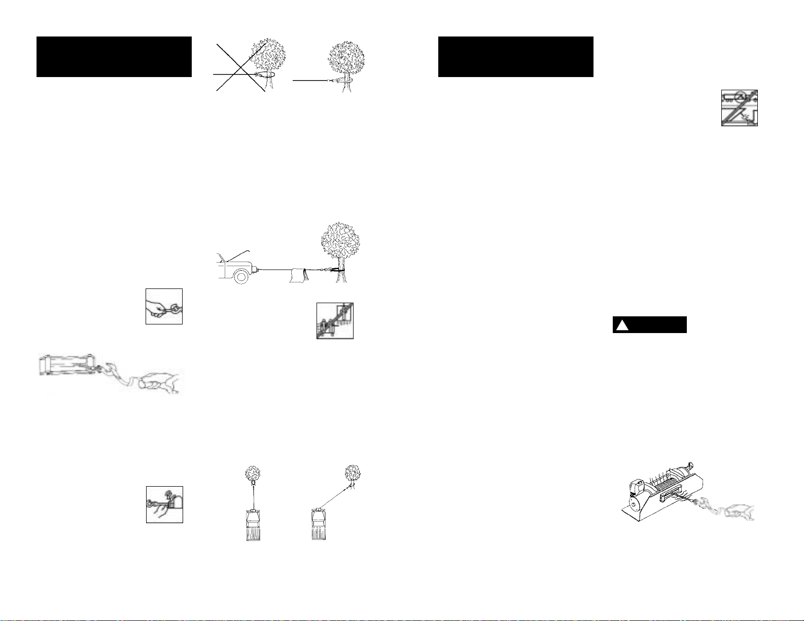
9. NEVER HOOK THE WIRE ROPE
BACK ONTO ITSELF because you
could damage the wire rope. Use
a nylon sling (Figure 3).
10. It is a good idea to lay a heavy
blanket or jacket over the wire
rope near the hook end when
pulling heavy loads (Figure 4). If
a wire rope failure should occur,
the cloth will act as a damper
and help prevent the rope from
whipping. Raise the hood of the
vehicle for added protection.
11. NEVER USE YOUR
WINCH FOR LIFTING
PEOPLE OR MOVING
PEOPLE.
12. Your winch is not intended for
overhead hoisting operations.
13. AVOID CONTINUOUS PULLS
FROM EXTREME ANGLES as this
will cause the wire rope to pile
up at one end of the drum
(Figure 5). This can jam the wire
rope in the winch, causing damage
to the wire rope or winch itself.
14. NEVER OBSCURE THE WARNING
INSTRUCTION LABELS.
15. Always operate winch with an
unobstructed view of the winching operation.
16. Equipment such as tackle, hooks,
pulley blocks, straps, etc. should
be sized to the winching task
and should be periodically
inspected for damage that could
reduce their strength.
17. NEVER RELEASE FREESPOOL
CLUTCH WHEN THERE IS A LOAD
ON THE WINCH.
18. STORE THE REMOTE PENDANT
ASSEMBLY IN A SAFE PLACE
when not in use to prevent use
by children or other unauthorized persons who could injure
themselves or others.
19. DO NOT OPERATE WINCH
WHEN UNDER THE INFLUENCE
OF DRUGS, ALCOHOL OR
MEDICATION.
20. ALWAYS UNPLUG THE REMOTE
PENDANT BEFORE WORKING IN
OR AROUND THE FAIRLEAD OR
WINCH DRUM (THE DANGER
ZONE) so that the winch cannot
be turned on accidentally.
21. When moving a load, slowly
take up the wire rope slack until
it becomes taut. Stop, recheck
all winching connections. Be
sure the hook is properly seated.
If a nylon sling is used, check the
attachment to the load.
22. When using your winch to move
a load, place the vehicle transmission in neutral, set vehicle
parking brake, and chock all
wheels
23. DO NOT USE THE WINCH TO
HOLD LOADS IN PLACE. Use
other means of securing loads
such as tie down straps.
Superwinch offers a
wide variety of tie
downs. Contact your
local Superwinch
dealer.
24. USE ONLY FACTORY APPROVED
SWITCHES, REMOTE CONTROLS
AND ACCESSORIES. Use of nonfactory approved components
may cause injury or property
damage and could void your
warranty.
25. DO NOT MACHINE OR WELD
ANY PART OF THE WINCH. Such
alterations may weaken the
structural integrity of the winch
and could void your warranty.
26. To avoid overheating the motor,
do not power the winch out
longer than 2 minutes.
The drum and
wire rope may
get very hot (Figure 6).
27. DO NOT CONNECT WINCH TO
EITHER 110 VOLT AC HOUSE
CURRENT OR 220V MAINS AS
WINCH BURNOUT OR FATAL
SHOCK MAY OCCUR!
28. Never allow shock loads to be
applied to winch or wire rope.
6
7
Figure 2
GENERAL SAFETY
INFORMATION
(CONT.)
Wrong Right
GENERAL SAFETY
INFORMATION
(CONT.)
Right
Wrong
Figure 5
Figure 3
Figure 4
Figure 6
HOT
HOT
DANGER
!

NOTES:
1. All dimensions are in inches
(millimeters).
2. Winch is mounted with 3/8-16
(M 10) hardware. Using 1/4
inch (6.4) thick steel baseplate,
bolt length to be 1 inch (25.4).
Bolts to be SAE Grade 8
(ISO 10.9) or stronger.
3. Use only square nuts in casting
for mounting. (See Figure 8.)
MOUNTING DIMENSIONS
10 (254.0)
4 1/2
(114.3)
1 13/32 (35.7)
13/32 (10.3)
Dia. Holes
(4) Places
Alternate Construction of
Structural Reinforcement
Weld
4 1/8 (104.8)
7 1/2 (190.5)
1/4 (6.4)
1 3/8 (34.9)
1/2 (12.7)
Max. Rad.
1 9/16 (39.7)
5/32 (4.0)
19/32
(15.1)
7/8
(22.2)
13/32 (10.3) Dia.
10 5/16 (261.9)
3/16 (4.8)
Opening
1 3/16 (30.2)
9 (228.6) Opening
9
29. Always operate your winch in
an underwound orientation
only.
MOUNTING YOUR WINCH
Superwinch mounting (fitting) fits
are available for most popular vehicles. If you can‘t locate a kit locally,
contact Superwinch at the address
listed on the front of this manual
for the name of a Superwinch dealer near you.
Detailed mounting instructions are
provided with each mounting kit.
Read and install carefully to ensure
proper winch alignment and trouble-free operation.
If a Superwinch mounting plate is
not used, refer to Figure 7 for a
guide to construct a mounting system.
Note: This winch MUST be mounted with the wire rope in the underwind direction.
Improper
mounting
could damage your winch, void
the warranty, and cause personal
injury.
MINIMUM ELECTRICAL
REQUIREMENTS
For 12 Volt winches, a 60 amp alternator and battery with 440 coldcranking amperes capacity are the
minimum recommended power
sources. If the winch is in heavy use,
an auxiliary battery and heavy duty
alternator with battery isolator are
recommended.
TOOLS REQUIRED
Open End Wrenches (Spanners):
*(2) 3/8", *(2) 1/2", *(2) 7/16",
*(2) 9/16"
(1) 1/4 inch Hex socket wrench or
straight blade screwdriver
*Adjustable (Crescent) Wrenches may be substituted.
1. Install mounting kit or structural
support for winch.
2. Attach the long black color-coded
wire to the motor case (see
Figure 10). Mount the winch to
the mounting kit base plate or
to the mount that you designed
(see Figure 7).
The 3/8-16 mounting bolts supplied are the correct length for
use with a 1/4" thick Superwinch
mounting plate.
The end of the
mounting bolts
must not contact the opposite side
of the support casting’s mounting
pocket (see Figure 8).
Such contact could lead to a damaged
casting, catastrophic failure of the
winch and void the warranty. Adjust
bolt length accordingly if a thicker
plate is used. The bolt threads must
engage all the nut threads.
Always place the square nuts (provided) in the casting pockets when
mounting your winch.
Do not sub-
stitute any
strength grade weaker than SAE
Grade 8 (ISO 10.9). Grade marking
is found on the bolt head and is
pictured in Figure 8.
3. If you choose to locate the winch
at a greater distance than the
wires provided will permit, it may
be necessary to purchase a larger
gauge wire to get the best performance from your winch. If the
total length of additional wire to
be added to the system exceeds
10 ft. (3m), use a larger wire
gauge size.
When attaching
wires to the
motor terminals and solenoids
(relays), hold the inner nut when
tightening the outer nut. Do not
allow the motor terminals to rotate
causing internal wire breakage or
part misalignment. Be especially
careful in preventing the solenoid
(relay) terminals from rotating. Any
rotation can damage the solenoid
(see Figure 9).
4. Disconnect the vehicle battery
leads.
Automobile bat-
teries contain
gasses which are flammable and
explosive. Wear eye protection
during installation and remove
all metal jewelry. Do not lean over
battery while making connections.
(Fig. 11).
INSTALLATION
Figure 10
Support Casting
Mounting Pocket
Square Nut
Flat Washer
Lock Washer
(Must not
touch)
Grade 8 Bolt
Mounting
Plate
10.9
Figure 9
8
Figure 8
Figure 7
Red
Black
Be Prepared
Figure 11
Overwind
Underwind
CAUTION
!
CAUTION
!
WARNING
!
CAUTION
!
DANGER
!
5. Route the long red and long
black coded wires through the
vehicle grille to the battery. To
ensure against insulation abrasion and/or cutting, apply several
layers of electrical tape where
wiring may come in contact with
sharp metal parts of the vehicle.
Attach the red color coded wire
to the battery positive terminal,
and reattach the terminal to the
battery.
If your vehicle is equipped with
side pole terminals, it may be
necessary to obtain auxilliary side
terminal bolts from your local
auto parts dealer to make these
connections.
Connect the long black color
coded wire to the battery negative terminal, and connect the
terminal to the battery.
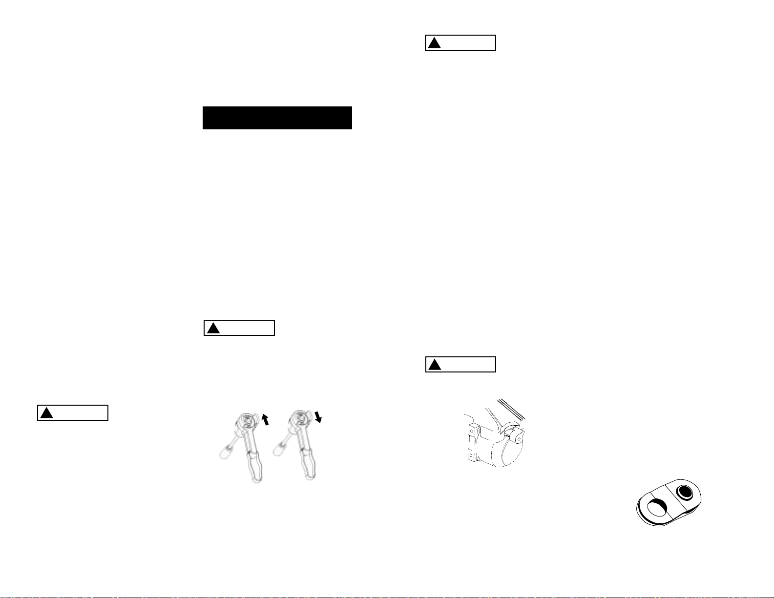
6. Turn the freespool clutch lever to
the “Free” position. Pull several
feet or wire rope off the drum.
Return the clutch lever back to
the “Engaged” position. Plug in
the remote pendant control.
Activate the toggle switch
momentarily to check wire rope
drum rotation and direction. If
the drum rotates in the wrong
direction, recheck your wiring.
To prevent unau-
thorized use of
the winch, remove pendant control
and store in a clean dry area such
as the glove box.
Under some circumstances it may
|be appropriate to install additional
circuit protection devices (circuit
breakers). If in doubt, seek appropriate expert advice. Superwinch
recommends that all winch electri-
cal systems can be readily and
quickly isolated from their electrical
supply in the event of an emergency. The winch electrical system
should always be isolated when
the winch is not in use.
The handheld pendant switch
activates a solenoid that activates
power to the winch motor.
To connect the pendant control,
remove the cover on the plug
receptacle and insert the plug end
of remote switch. The plug on the
pendant control cord is keyed and
will fit into the socket only one
way.
The toggle switch returns to the
“Off” position when released.
To change direction, move the
toggle in the other direction.
The switch
assembly must
be kept free of dirt and moisture
to ensure safe operation.
The switch
assembly must
be kept free of dirt and moisture
to ensure safe operation.
PULLING OUT THE WIRE ROPE
The wire rope has been installed on
your winch under minimal load at
the factory. The wire rope must be
respooled onto the drum under
load so that the outer layers will
not draw down into the inner ones
thereby damaging the wire rope.
Rotate the clutch lever to the “Free
position as shown in Figure 13. If
there is a load on the wire rope, the
clutch lever may not turn easily. DO
NOT FORCE THE CLUTCH LEVER.
Release tension on the wire rope by
jogging out some of the wire rope,
then try releasing the clutch. Pull
out the wire rope and secure to
anchor or load. Check that there
are at least five (5) turns of wire
rope left on the drum. Re-engage
the drum by rotating the clutch
lever to the “Engaged” position
(see Figure 13).
Lever must be
in the engaged
position and locked before winching
TIPS FOR EXTENDING THE LIFE OF
YOUR WINCH
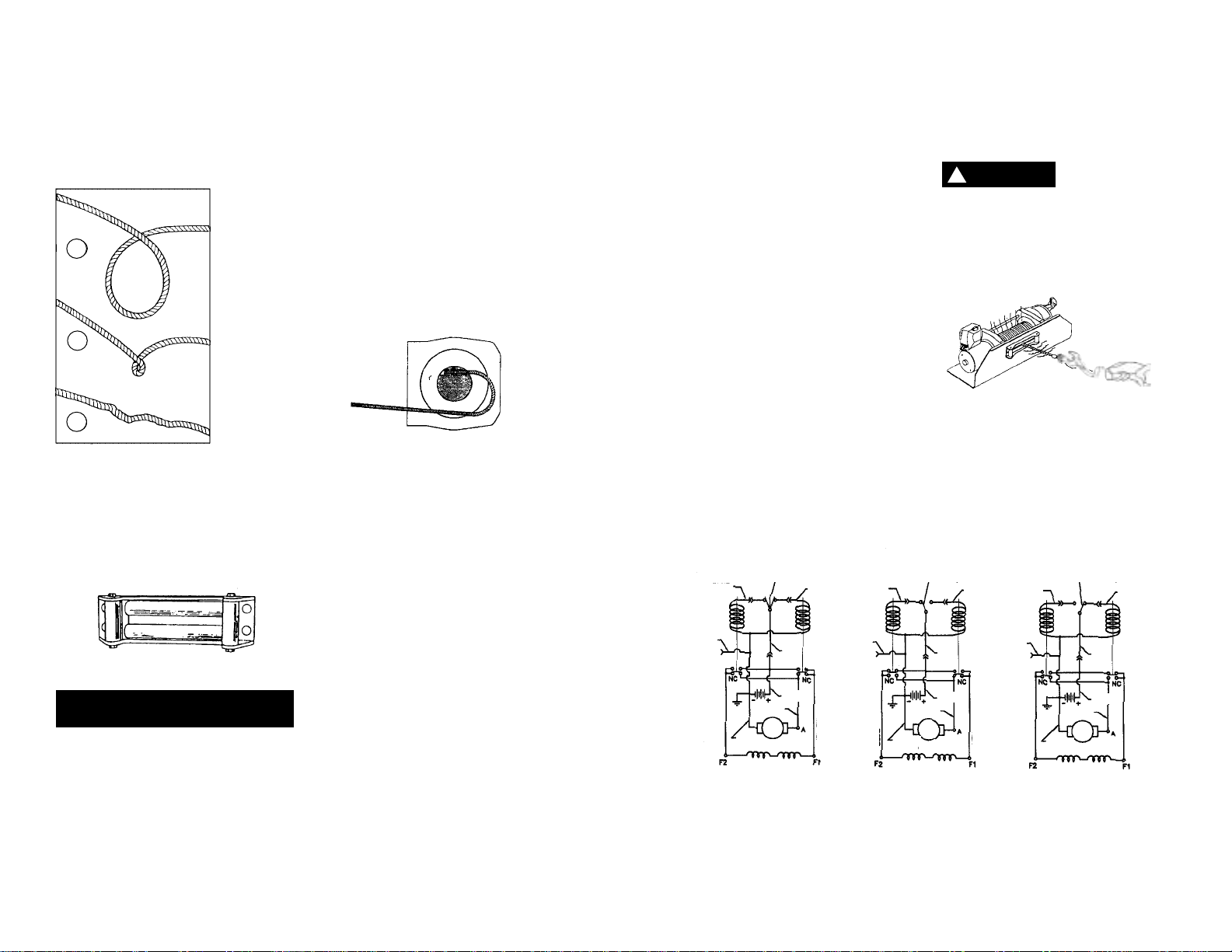
1. KEEP A TIGHTLY WOUND WIRE
ROPE DRUM. Do not allow the
wire rope to become loosely
wound. A loosely-wound spool
allows a wire rope under load to
work its way down into the layers
of wire rope on the drum. When
this happens, the wire rope may
become wedged within the body
of the windings damaging the
wire rope. To prevent this problem, keep the wire rope tightly
and evenly wound on the drum
at all times. A good practice is to
rewind the wire rope under tension after each use. One way to
do this is to attach the hook to a
stationary object at the top of a
gradual incline and winch your
vehicle up the incline.
2. DO NOT ALLOW WINCH MOTOR
TO OVERHEAT. Remember, the
winch is for intermittent use only.
During long or heavy pulls the
motor will get hot. The internal
parts will be hotter than the case.
To check the motor temperature,
stop winching and carefully touch
the motor case, if the motor is
uncomfortably warm, allow the
motor to cool before continuing.
KEEP THE ENGINE RUNNING TO
RECHARGE THE BATTERY during
this break.
3. To maximize winch and wire rope
life, use a pulley block to double
line heavier loads (Figure 14).
10
Figure 12
11
Figure 13
ENGAGED
FREE
Figure 14
OPERATION
Rope In
Rope Out
CAUTION
!
CAUTION
!
CAUTION
!
CAUTION
!
12
4. The pull required to start a load
moving is often much greater
than the pull required to keep it
moving. AVOID FREQUENT STOPPING AND STARTING during pull.
5. PREVENT KINKS BEFORE THEY
OCCUR.
6. EQUIPPING THE WINCH WITH A
ROLLER FAIRLEAD will substantially reduce wear on the wire rope
during angle pulls (Figure 16).
The rollers eliminate heavy rubbing and abrasion to the wire rope.
Periodically check tightness of
mounting bolts and electrical connections. Remove any dirt or corrosion that may have accumulated on
the electrical connections.
Repairs should be done by
Authorized Superwinch Repair
Centers ONLY. Do not attempt to
disassemble the gearbox.
Disassembly will void warranty.
LUBRICATION
The gearbox and drum bearing are
permanently lubricated with a high
performance gear lube. If relubrication is necessary (after repair or
disassembly) only use factory
approved grease (Superwinch Part
No. 90-15020).
REPLACING THE WIRE ROPE
Never substitute a heavier or lighter
wire rope. Never use rope made of
any other material other than wire.
Always replace damaged wire
rope with manufacturer’s identical replacement part (see
Replacement Parts list). Pass attaching end of wire rope through the
fairlead (if equipped) and attach it
to the drum. When inserting the
wire rope into the drum, insert it
into the correct end of the hole
provided (Figure 17). Tighten the set
screw securely.
It is important that the wire rope be
wound tightly onto the drum. A
good way to do this is to attach the
wire rope hook to a fixed object at
the top of a slight incline, then
winch the vehicle up the incline.
MAINTENANCE
13
Figure 15
a
b
c
a. This is the start
of a kink. Wire
rope should be
straightened.
b. Wire rope was
pulled and loop
has tightened into
a kink. Wire rope
is now permanently damaged and
must be replaced.
c. Result of kinking is that each
strand pulls a different amount causing strands under
greatest tension
to break and
reduce load capacity of wire rope.
The wire rope
must be replaced.
Figure 16
Figure 17
BRAKE OPERATION
Your S9000 winch has a drag brake
that stops and holds loads up to
4,500 lbs. (2041 kg) on the first layer
of wire rope closest to drum. Each
additional layer of wire rope
reduces brake capacity approximately 10%. When powering the
winch in, the brake is disengaged
and does not become activated
until the motor is turned off and
the load tries to pull the wire rope
off the drum. When the winch is
powered out, as in releasing a load,
the brake is engaged and the motor
must over power the brake drag to
rotate the drum. Therefore, it is
normal for the winch to operate
faster in one direction than the
other. The brake is designed for the
wire rope to be used in the underwind position only. Drum must turn
clockwise, looking from motor
end, when winching in. Do NOT
overwind.
Powering against the brake will
cause heat to build up in the drum
and may transfer heat to the wire
rope (Figure 18). DO NOT POWER
OUT FOR MORE THAN 20 FEET (6m)
OR 2 MINUTES.
The drum and
wire rope may
get very hot.
When wire rope is removed from
the drum, as in bringing the hook
to the load, the freewheel feature
of the winch should be used.
Figure 19
Figure 18
HOT
HOT
HANDHELD REMOTE
DIRECTIONAL SWITCH
(Spring to Center)
HANDHELD REMOTE
DIRECTIONAL SWITCH
(Rope-In Position)
HANDHELD REMOTE
DIRECTIONAL SWITCH
(Rope-Out Position)
BLUE BLUE BLUE
YELLOWYELLOWYELLOW
BLACK
GROUND
BLACK
GROUND
BLACK
GROUND
RED
RED
RED
WHITE
WHITE
WHITE
BLACK
BLACK
BLACK
MOTOR
MOTOR
MOTOR
FIELD WINDINGS
FIELD WINDINGS
FIELD WINDINGS
OFF WIRE ROPE IN
WIRE ROPE OUT
BLUE
BLUE
BLUE
YELLOW
YELLOW
YELLOW
RED
RED
RED
DANGER
!

15
1
2
3
4
37
10
5
13
11
12
8
45
6
30
32
77
78
70
9
29
N
O
TE G
RO
O
V
E
O
RIEN
TATIO
N
D
15
16
17
27
28
56
55
54
57
53
58
53
60
51
50
49
44
43
42
41
40
39
38
68
65
36
35
34
81
33
80
7
31
46
59
14
1 12 VDC Motor 90-33333 1
24 VDC Motor 90-33334 1
2 Motor Spacer 90-10354 1
3 Ball Bearing 94-23079-05 1
4 1/4-20 x 5/8 Self tapping hex head screw 90-23039-10 3
6 Motor Adapter 90-32165 1
7 Outboard Drum Support w/ (10 & 37) 90-32257 1
8 Drum Bearing 90-12575 1
10 Winding Direction Label 92-10211 1
11 Drag Button Spring 90-23152-08 1
12 Drag Button 90-22612 1
13 Cover w/ Labels (specify model # when ordering) 90-40088 1
14 Drum 90-31069-04 1
15 M8 x 10 Socket Set Screw 94-23164-09 1
16 Drive Shaft Coupling 90-22110 1
17 Washer 90-23120-08 2
D Brake Assembly 90-25036 1
18 Not applicable this model ——
19 Not applicable this model ——
20 Not applicable this model ——
21 Not applicable this model ——
22 Not applicable this model ——
23 Not applicable this model ——
24 Not applicable this model ——
25 Not applicable this model ——
26 Not applicable this model ——
27 Drive Shaft Assembly 90-22254 1
28 Thrust Washer 90-12574 1
29 5/16 x 100 ft. Wire Rope w/o Hook 1580 1
30 Clevis Hook Assembly 94-20116 1
31 Inboard Drum Support w/ 37 90-32258 1
32 1/4-20 x 3 1/4 Socket Head Cap Screw 90-23015-05 4
33 3/8-16 Square Nut 90-23084-04 4
34 3/8 Flat Washer 92-23027-05 4
35 3/8 Lock Washer 92-23057-01 4
36 3/8-16 x 1 Hex Head Bolt, Grade 8 90-23226-01 4
38 Drum Bearing 90-12575 1
39 Drum Driving Plate 90-22183-01 1
40 Output Ring Gear 90-32232-01 1
REPLACEMENT
PARTS LIST
Reference
Number Description Part Number Qty
79
14
73

41 Ring Gear Bearing 90-22607 1
42 Carrier Bushing 90-10417 1
43 Planet Carrier Assembly 90-32238 1
44 Gearbox Bushing 90-10418 1
45 Plastic Closure 94-23171-05 2
46 8-32 x 3/8 Pan Head Screw 90-23032-17 1
47 Not applicable this model ——
48 Not applicable this model ——
49 Fixed Ring Gear 90-32233-01 1
50 Lock Pin 90-22252-01 1
51 Gearbox Housing (inc. 56-58, 60) 90-32296 1
53 1/4-20 x 5/8 Self Tapping Hex Head Screw 90-23039-10 4
54 Clutch Lever 90-32248 1
55 #8 Int Tooth Lock Washer 90-23048-03 1
56 Dust Cover 90-22103 1
57 Plug 94-23171-04 1
58 Rubber Washer 92-10194 2
59 Clutch Spring 90-23152-07 1
60 Push-on Retainer 90-23213-04 2
65 2 AWG x 8' Lead Wire Assembly (black) 90-22635-47 1
68 Handsaver 87-31120 1
NS 7" Long Wire Tie 94-23058-04 6
NS Grease (for one relube) 90-15020 1
ACC Roller Fairlead 2539 1
70 Remote Switch Pendant (15') 90-33450-01 1
71 Toggle Switch 90-14141 1
73 Connector Assembly w/ Wires 90-14140 1
77 12VDC Solenoid 90-14452 1
24VDC Solenoid 90-14454 1
78 Solenoid Mounting Plate w/ Studs 90-32436 1
79 10-32 x 1/2 Self Tapping Hex Washer Head Screw 92-23039-02 4
80 Tie Rod 90-20033 1
81 1/4-20 x 3/4 Socket Head Cap Screw 90-23055-06 2
NS 12V Motor Brush Repair Kit 90-10414-05 1
ACC 12V Circuit Breaker Assembly 2232 1
ACC 24V Circuit Breaker Assembly 2232A 1
NS Not Shown
ACC Accessory
REPLACEMENT
PARTS LIST
Reference
Number Description Part Number Qty
17
16
NOTES

USA
Superwinch Inc.
Winch Drive
Putnam, CT 06260
phone: 860-928-7787
repair@superwinch.com
Electric Motor Repair
2010 North 4th Street
Minneapolis, MN 55411
phone: 612-588-4693
Berens & Associates
124 Hegenberger Loop
Oakland, CA 94621
phone: 800-540-2858
berens94621@yahoo.com
Zorko’s Alternator Service
241 Wells Road
Home, PA 15747
phone: 800-468-5055
zasapw@microserve.net
Electric Motors of Iowa City
50 Commercial Court
Iowa City, IA 52246
phone: 319-354-4040
emic4040@aol.com
CANADA
Demand Electric
228-39th St. N.E.
Calgary, AB T2E 2M5
403-230-2709
Harold Supply
3 Southerland Ave.
Sudbury, Ont. P3C 3A7
705-761-4455
Explora Industries Ltd.
9605-5th Ave.
Edmonton, AB T6E 0B2
780-430-8591
Dayworth Sales
1 Saunders Rd. Unit 2
Barrie, Ont. 9A7 9A7
705-726-7778
Les Equipment Twin
10401 Parkway Blvd.
Ville D’Anjou, PQ H1J 1R4
514-353-1190
Buffalo Industries
251-253 Princess Street
Winnipeg, Manitoba R2C 1M1
204-942-1951
Power Plus Tool Repair
57 Millenium Ave.
Moncton, NB E1E 2G2
560-855-8665
Muskoka Auto Parts
11 King William St.
Huntsville, Ont. P1H 2K8
705-789-2321
Lou Dennis Auto
Hiway 11 South
Sundridge, Ont. P0A 1Z0
705-384-5345
Outdoors Plus
128 Regional St.
P.O. Box 1349
Port Aux Basques, NF A0M 1C0
709-695-7533
Bobcaygeon Auto and Marine
91 Main St.
Bobcaygeon, Ont. K0M 1A0
705-738-2317
MAP Bracebridge
19 Taylor Rd.
Bracebridge, Ont. P1L 1W3
705-645-8785
MAP Fenelon Falls
165 Lindsay St.
Fenelon Falls, Ont. K0M 1N0
705-887-6232
Central Electric Motor Rewind
#1-1960 Windsor Rd.
Kelowna, NC V1Y 2Y3
250-860-4415
jnelsoncentral@netscape.net
Delta Tool Repair Limited
114-7533, 135th St.
Surrey, BC V3W 0N6
604-591-3230
Ted's Power Tool Repair
426-44th St. East
Saskatoon, SK S7K OW1
306-934-6155
Bob's Electric Truck Servise
845-B Macdonald Ave.
Regina, SK S4N 2X5
306-721-4148
Off Road Canada
251-12th St. "B" North
Lethbridge, AB T1H 2K8
403-327-7722
Gary's Starter & Alternator
P.O.Box 7 Site 4
RR 1 Mount Uniacke B0N 1Z0
Contact: Gary Thorne
902-757-2388
Power Blitz Mftg. & Maintenance
577 Edgeley Blvd. Unit 6
Concord, Ont. L4K 4B2
905-669-8209
ali@powerblitz.com
Bruce's Recreaction
92 Balbo Dr.
Shoal Harbour Nfld A5A 4A8
709-466-3355
Atlantic Recreation & Marine
5 School St.
Sydney, Nova Scotia
B1S 3G1
902-567-1697
sbidart@thearm.ca
UNITED KINGDOM
Superwinch, LTD
Abbey Rise, Whitchurch road
Tavistock, Devon PL19 9DR
+44 (0) 1822 614101
WORLDWIDEContact your Local
Superwinch Distributor or callSuperwinch.
TROUBLESHOOTING
CHART
Motor will not operate 1. Damaged or stuck 1.
CAUTION:
Disengage
or runs in one direction solenoid; most likely clutch before performonly caused by not holding ing this test to prevent
the inner nut to keep the powering the wire rope
stud from turning when drum. If a solenoid sticks
attaching wire to solenoid once, it is likely to stick
again and must be
replaced immediately.
Tap solenoid to free
stuck contacts. Check
by applying voltage to
the small solenoid terminal. Be sure solenoid
is grounded back to
source. A solenoid that
is not stuck will make an
audible “click” when first
energized
2. Switch inoperative 2. Replace Switch
3. Broken wires or bad 3. Check for poor connectconnection tions. CAUTION: Always
use two wrenches
(spanners). (See Figure 9)
4. Damaged motor 4. Replace or repair motor
5. Solenoids not grounded 5. Check the ground path
between battery
negative and solenoid base
Winch will not shut off 1. Solenoid stuck “on” 1. If solenoid sticks on,
reverse direction and hold
trigger switch on until the
power lead can be disconnected. A safety on-off
switch is available as an
accessory
Motor runs extremely hot 1. Long period of operation 1. Allow to cool
2. Damaged motor 2. Replace or repair motor
3. Damaged brake 3. Replace or repair brake
Motor runs but with 1. Weak battery 1. Recharge or replace
insufficient power or battery. Check charging
line speed system
2. Battery to winch wire 2. Use larger gauge wire.
too long
3. Poor battery connection 3. Check battery terminals for
corrosion. Clean as
required
4. Poor ground 4. Check and clean connections
5. Damaged brake 5. Repair or replace brake
Motor runs but drum 1. Clutch not engaged 1. Engage clutch
does not turn
Winch runs backwards 1. Motor wires reversed 1. Recheck wiring
2. Solenoids wired incorrectly 2. Recheck wiring
Will not hold load 1. Excessive load 1. Reduce load or double line
2. Worn or damaged brake 2. Repair or replace brake
Symptom Possible Cause(s) Corrective Action
19
18
If a problem arises, contact your nearest
Superwinch dealer or repair center.
WARRANTY REPAIR CENTERS

MANUAL DEL PROPIETARIO
INSTALACIÓN • OPERACIÓN • MANTENIMIENTO
PRECAUCIONES DE SEGURIDAD • PIEZAS DE
REPUESTO
Cabrestante eléctrico S9000
de 12 y 24 Voltios CD Modelos
1916 y 1918
LEA Y ENTIENDA ESTE MANUAL ANTES DE INSTALAR Y
OPERAR SU PRODUCTO SUPERWINCH
Superwinch, Inc. Superwinch, Ltd.
Winch Drive Abbey Rise, Whitchurch Road
Putnam, CT 06260 Tavistock, Devon PL 19 9DR
U.S.A. England
Tel. (860) 928-7787 Tel. +44 (0) 1822 614101
Fax (860) 928-1143 Fax +44 (0) 1822 615204
PRECAUCION
!
VALID WORLDWIDE
LIMITED WARRANTY
Superwinch Inc. (“Seller”) warrants to the original buyer (“YOU”) all parts and components except
wire rope to be free of defects in materials and workmanship for a period of ONE (1) year from
provable date of purchase. Any Superwinch product which is defective will be repaired or replaced
without charge to you, upon compliance with these procedures. The warranties set forth herein
are exclusive and in lieu of all other warranties, whether oral or written, express or implied.
LIMITED WARRANTY PERFORMANCE PROCEDURE
Upon discovery of a defective Superwinch product, you shall mail to the Seller at his factory or to
any Factory Authorized Service Center written notice of such defect and mail, ship or otherwise
deliver the defective Superwinch, postage or shipping prepaid. Repairs or replacements by Seller
under this Limited Warranty will normally be accomplished within fifteen (15) business days after
receipt of the defective Superwinch. Seller or its Authorized Agents may make reasonable charges
for parts and labor for repairs not covered by this Limited Warranty.
WARRANTY AND REMEDY LIMITATIONS AND EXCLUSIONS
Repair and/or replacement of the defective Superwinch or component part thereof as provided
herein is the exclusive remedy for you. The following exclusions or limitations of warranties and
limitations of remedies shall be expressly applicable:
A. Express Warranties. Seller Warrants that the Superwinch is as described in the ”Superwinch
Owner’s Manual” provided herewith; no other express warranty is made in respect to the
Superwinch. If any model or sample was shown to you, such model or sample was used for illustrative purposes only, and shall not be construed as a warranty that the Superwinch will conform to
the sample or model. SELLER MAKES NO EXPRESS WARRANTY WITH RESPECT TO THE WIRE ROPE
INCORPORATED IN THE PRODUCT.
B. Implied Warranty. The implied warranty of merchantability and all other implied warranties
shall only extend from the provable date of purchase for one (1) year. The wire rope is sold ”as is,”
without any implied warranties. Some states within the U.S.A. do not allow limitations on how
long an implied warranty lasts, so the above limitation may not apply to you.
C. Incidental and Consequential Damages. SUBJECT TO THE SELLER’S LIMITED WARRANTY OBLIGATIONS SET FORTH HEREIN, SELLER SHALL NOT BE RESPONSIBLE FOR INCIDENTAL DAMAGES OF
ANY KIND, OR FOR CONSEQUENTIAL DAMAGES TO PROPERTY, LOSS OF PROFITS AND LOSS OF USE
WHICH MAY BE CAUSED BY ANY DEFECT IN, OR MALFUNCTION, OR FAILURE OF THE ENCLOSED
SUPERWINCH. SOME STATES WITHIN THE USA DO NOT ALLOW THE EXCLUSION OR LIMITATION OF
INCIDENTAL OR CONSEQUENTIAL DAMAGES, SO THE ABOVE LIMITATION OR EXCLUSION MAY
NOT APPLY TO YOU.
D. Condition of Warranty. Seller shall not be required to comply with its warranty duties provided
herein if the defect, malfunction, or failure of the Superwinch was caused by damage (not resulting
from defective or malfunctioning components) or unreasonable use by you. Unreasonable use shall
include, but not be limited to, the failure to provide reasonable and necessary maintenance or
installation or use of the Superwinch without compliance with the instructions contained in the
Superwinch Owner’s Manual, and subjecting the Superwinch to loads in excess of the load listed in
the Owner’s Manual for the particular model number. Seller’s liability under this warranty or for any
loss or damage to the Superwinch product shall not exceed the cost of correcting the defects in or
replacing the Superwinch product, and upon expiration of the warranty period, all such liability
shall terminate. The agents, dealers and employees of the Seller are not authorized to make modifications to this warranty, or additional warranties binding on the Seller. Accordingly, additional statements, whether oral or written, do not constitute warranties and should not be relied upon.
LEGAL REMEDIES OF BUYER
This Limited Warranty gives you specific legal rights, and you may also have other rights which
may vary from state to state within the USA and from country to country. You also have implied
warranty rights. In the event of a problem with Limited Warranty service or performance, you may
be able to go to small claims court, a state court, or federal district court in the USA or to appropriate jurisdictions outside the USA.
INQUIRIES
Any inquiries regarding compliance with warranties provided herein may be addressed in writing
to: Superwinch Inc., Winch Drive, Putnam, CT 06260, USA or to: Superwinch Ltd., Abbey Rise,
Whitchurch Road, Tavistock, Devon PL 19 9DR, England.
LIMITED WARRANTY

Gracias por comprar un cabrestante S9000 de Superwinch. Éste ha sido diseñado y fabricado
para proporcionarle años de operación sin problemas. Esperamos que esté satisfecho con su
rendimiento. Si no lo está por cualquier motivo, por favor comuníquese con nuestro
Departamento de Servicio al Cliente al: (860) 928-7787 en E.U.A.; +44 (0) 1822 614101
en Inglaterra.
Cuando solicite información o piezas de repuesto, siempre dé la siguiente información:
1. Número de Pieza del cabrestante (1916, 1918)
2. Número de Serie (se encuentra en la pieza de fundición del soporte del tambor.)
3. Número de Pieza (se encuentra en la Lista de piezas de repuesto)
4. Descripción de la Pieza
Por favor lea y entienda este Manual del propietario antes de instalar y usar su cabrestante.
Ponga particular atención a la Información General de Seguridad. Su cabrestante es una
máquina muy poderosa. Si se usa sin precaución o inadecuadamente, existe la posibilidad
de causar daños a bienes o lesiones personales. Hemos incluido varias características en este
cabrestante para reducir esta posibilidad. No obstante, su seguridad depende en última
instancia en su precaución al usar este producto.
Indica una situación de peligro inminente que, de no evitarse,
dará como resultado muerte o lesiones graves.
Indica una situación de peligro potencial que, de no evitarse,
podría dar como resultado muerte o lesiones graves.
Indica una situación de peligro potencial que, de no evitarse,
puededar como resultado lesiones leves o moderadas. Esta nota
se utiliza también para alertarle sobre prácticas inseguras
.
Se usan los siguientes símbolos en el producto y en el Manual del Propietario:
Nota: Indica información adicional en los procedimientos de instalación y operación
de su cabrestante.
La instalación correcta de su cabrestante S9000 es un requisito para su operación correcta.
Si piensa instalar su cabrestante X9 en el extremo delantero de su vehículo, use el juego de
montaje (adaptación) S9000 que ha sido diseñado y manufacturado por Superwinch para
recibir su cabrestante y adaptarse a su vehículo.
Por favor tome nota: El cabrestante Superwinch modelo X9 está diseñado principalmente
para usarse montado al frente de un vehículo y para otro servicio intermitente de uso general. Este cabrestante no está diseñado para usarse en aplicaciones de grúa ni Superwinch
garantiza que sea idóneo para tal uso. Para mayor información, por favor comuníquese con
nuestro Departamento de Servicio al Cliente.
Tome nota de los requisitos eléctricos del cabrestante S9000 que compró:
Núm. de pieza 1916 Sistema de CD 12 Voltios Solamente
Núm. de pieza 1918 Sistema de CD 24 Voltios Solamente
¡Felicidades por su elección!
22
Descripción Cantidad
Conjunto del cabrestante con cable de alambre 1
Tornillos allen 1/4''-20 4
Tuercas cuadradas de 3/8''-16 4
Rondanas planas de 3/8” 4
Rondanas de presión de 3/8'' 4
Tornillo de cabeza hexagonal de 3/8”-16 4
Barra protectora para manos 1
Tiras para atar cables de 17.78 cm (7'') 6
Gancho de horquilla 1
Conjunto de pendiente remoto 4
Conjunto de cables conductores largos (codificados amarillo) 1
INTRODUCCIÓN
Motor eléctrico – De 4.2 hp pico
(3.1 kw) Embobinado Serie 12V
o 3.5 hp pico (2.6 kw) Embobinado
Serie 24V.
Frenado – El freno de arrastre de
una dirección retendrá una carga
de 2,041 kg (4,500 lb) en la primera
capa.
Tambor – Acero maquinado
que gira sobre rodamientos de
copolímero sin mantenimiento.
Embrague de carrete libre – Operado
por una palanca de acción fácil que
desembraga el motoreductor para
permitir que el cable de alambre sea
sacado sin usar corriente eléctrica.
Un mecanismo de arrastre con
resorte reduce el latigueo y el tironeo cuando se tira del cable de
alambre.
Interruptor remoto – 4.5 m (15')
Conjunto de interruptor de mano
tipo pendiente con interruptor de
reversa con interbloqueo y gatillo.
Montaje – Se ofrecen juegos de
montaje opcionales, diseñados a la
medida, para instalaciones sobre el
chasís del vehículo.
CARACTERÍSTICAS
Esta caja contiene los siguientes artículos. Por favor desempáquelos cuidadosamente. Lea las instrucciones antes de comenzar.
DESEMPAQUE
23
Pendiente**
10% (6º) 20% (11º) 30% (17º) 60% (31º) 100% (45º)
Lbs.
kg
45,225
20514
30,600
13880
23,500
10659
15,000
6804
11,575
5250
* Las especificaciones asumen un 10% de coeficiente de fricción.
** Una pendiente de 10% es una elevaciónn de 30.5 cm en 3.05 m (1 pie en 10 pies) También muestra una pendiente
en grados aproximados.
CAPACIDADES DE CARGA RODANTE*
Leer el Manual
del Propietario
Siempre use la
barra protectora
para manos
Manténgase alejado
del cabrestante, el
cable de alambre y
el gancho durante
la operación
Nunca use el
cabrestante para
levantar o mover
personas
Nunca use el
cabrestante para
sostener cargas
Superwinch no es responsable de errores de impresión hechos inadvertidamente durante la producción de este manual
PELIGRO
!
ADVERTENCIA
!
PRECAUCION
!

25
RENDIMIENTO
Su cabrestante S9000 es una
máquina muy poderosa. Trátelo
con respeto, úselo con precaución
y siempre siga estos lineamientos
de seguridad.
La respons-
abilidad
para la instalación y operación
seguras del cabrestante y la prevención de lesiones personales y daños
a la propiedad es, en última instancia, suya, el operador. No existe sustituto para el buen juicio y la precaución al operar el cabrestante.
El cable de
alambre puede
romperse antes de que el cabrestante
entra en pérdida. Para cargas pesadas,
use un bloque de poleas para reducir
la carga sobre el cable de alambre.
1. El S9000 tiene una clasificación de
4,082 kg (9,000 lb)(línea sencilla) en la
capa de cable más cercana al tambor.
NO LO SOBRECARGUE. NO TRATE DE
TIRAR CARGAS PESADAS DE FORMA
PROLONGADA. No mantenga encendido el cabrestante si el motor entra
en pérdida. Las sobrecargas pueden
dañar el cabrestante y/o el cable de
alambre y causar condiciones de
operación inseguras. PARA CARGAS
MAYORES DE 2,721 KG (6,000
LIBRAS), RECOMENDAMOS EL USO
DEL BLOQUE DE POLEAS OPCIONAL
PARA DUPLICAR EL CABLE DE ALAMBRE (Figuras 1 y 14). Esto reduce la
carga sobre el cabrestante y la tensión
sobre el cable de alambre en un 50%
aproximadamente. Si lo monta en la
parte trasera del vehículo, sujételo al
chasís u otra parte que soporte carga.
El motor del vehículo debe estar funcionando durante la operación del
cabrestante para reducir la descarga
de la batería y aumentar la potencia
y velocidad del cabrestante. Si se acti-
va el cabrestante durante períodos
considerables de tiempo con el motor
apagado, la batería podría descargarse y ya no podría arrancar el motor.
2. DESPUÉS DE LEER Y ENTENDER ESTE
MANUAL, APRENDA A USAR
SU CABRESTANTE. Después
de instalar el cabrestante,
practique usándolo para
familiarizarse con su
operación cuando surja la
necesidad de usarlo.
3. NO «mueva» su vehículo para ayudar
al cabrestante a tirar de la carga. La
combinación del cabrestante y el
vehículo tirando a la vez puede sobrecargar el cable de alambre y el
cabrestante.
4. MANTENGA EL ÁREA DE MANIOBRAS
LIBRE DE OBSTRUCCIONES. No permita que haya personas en el área
durante las operaciones de tiro.
SIEMPRE MANTÉNGASE ALEJADO DEL
CABLE DE ALAMBRE, EL GANCHO Y
EL CABRESTANTE. EN EL REMOTO
CASO DE FALLA DE CUALQUIER COMPONENTE, ES MEJOR ESTAR LEJOS DEL
PELIGRO.
5. INSPECCIONE FRECUENTEMENTE EL
CABLE DE ALAMBRE Y EL EQUIPO. UN
CABLE DE ALAMBRE DESHILACHADO
CON HILOS ROTOS DEBE REEMPLAZARSE INMEDIATAMENTE.
Siempre reemplace el cable de alambre con la pieza de repuesto idéntica
del fabricante (vea la lista de piezas
de repuesto). Revise pe- riódicamente
la instalación del cabrestante para
asegurarse que todos los tornillos
estén firmes.
6. USE GUANTES DE CUERO PESADO al
manejar el cable de alambre. NO DEJE
QUE EL CABLE DE ALAMBRE SE
DESLICE EN SUS MANOS NI AÚN
CUANDO USE GUANTES.
INFORMACIÓN GENERAL
DE SEGURIDAD
Capa del Cable Capacidad Máxima de Tiro
de Alambre lb kg
1 9,000 4082
2 7,365 3340
3 6,230 2825
4 5,400 2450
5 4,765 2160
Velocidad Velocidad Voltaje
Carga* 12 Voltios 24 Voltios del Motor Amps.
lbs kg ft/min m/min ft/min m/min 12V 24V
SERVICIO
INTERMITENTE
Carga de trabajo* . .4082 kg (9,000lbs)
Carga de pérdida 12 v*, 24 v*
. . . . . . . . . . . . . . . . 5760 kg (12,700 lb)
Cable de alambre . . . . (5/16" x 100')
Motor 12 v . . . . . . . . . . . . . . 4.2 hp
(3.1 kW) pico
Motor 24 v . . . . . . . . . . . . . . 3.5 hp
(2.6 kW) pico
Relación de engranes . . . . . . . 253:1
*En base al rendimiento de la primera capa
ESPECIFICACIONES
24
Un cabrestante eléctrico es como
cualquier otra herramienta eléctrica, como por ejemplo un taladro o
una sierra. No se debe permitir que
el motor eléctrico se caliente excesivamente. Las precauciones normales extenderán la vida de su
motor. Mantenga la duración de los
tiros tan breve como sea posible. Si
el extremo del motor se calienta de
modo que resulte incómodo
tocarlo, deje de operar el
cabrestante y permita que
el motor se enfríe.
Si el motor del
cabrestante entra
en pérdida, no siga aplicándole energía.
Figura 1
Línea sencilla
Línea doble
0 0 38,2 11,6 38,0 11,6 73 42
1,000 454 18,0 5,5 21,7 6,6 130 72
2,000 907 13,8 4,2 17,1 5,2 165 90
4,000 1814 9,0 2,7 12,0 3,6 240 133
6,000 2721 6,0 1,8 8,3 2,5 316 181
9,000 4082 2,5 0,8 3,5 1.0 420 252
PRECAUCION
!
ADVERTENCIA
!
PELIGRO
!

7. Nunca use el cabrestante con
menos de 5 vueltas de cable de
alambre en el tambor de
cabrestante, ya que el sujetador
del extremo del cable de alambre
no resistirá la carga. El cable de
alambre de su cabrestante S9000
tiene un «indicador de advertencia» rojo en cada extremo. El «indicador de advertencia» del extremo
del cabrestante le advierte que el
cable de alambre está en la vuelta
5 o cerca de ella. El «indicador de
advertencia» del extremo del gancho del cable de alambre le
advierte que el gancho está acercándose al cabrestante. Siempre
use la protectora para manos cuando guíe el cable de alambre hacia
adentro o afuera (vea la Figura 2).
Al usar su cabrestante,
la pintura roja se desgastará con
el uso normal. Cuando esto suceda,
renueve la pintura roja
ya que ésta es una característica de seguridad
del cabrestante.
8. Manténgase alejado del
cabrestante, el cable tenso y el gancho al operar el cabrestante. Nunca
introduzca su dedo a través del
gancho. Si su dedo queda atrapado
en el gancho, podría
perderlo. Nunca guíe el
cable hacia el tambor
con la mano.
9. Nunca enganche el cable de alambre sobre sí mismo porque podría
dañarlo. Use una eslinga
de nilón
(Figura 3).
10. Es una buena idea poner una
frazada pesada o abrigo sobre
el cable de alambre cerca del
ex-tremo del gancho al tirar de car
gas pesadas (Figura 4). Si falla el
cable de alambre, la tela actuará
como atenuador y evitará
que el cable de alambre latiguee.
Le-vante la capota del motor del
vehículo para aumentar la protec-
ción.
11. Nunca use su
cabrestante para levantar o mover gente.
12. Su cabrestante no ha sido
di- señado para operaciones
de izado.
13. Evite tirar continuamente desde
ángulos extremos, ya que esto
causará que el cable de alambre
se apile en un extremo del tambor
(Figura 5). Esto puede atorar
el cable de alambre en el
cabrestante, dañando tanto
el cable de alambre como el
cabrestante.
14. Nunca tape las etiquetas de
instrucciones de advertencia.
15. Siempre opere el cabrestante
teniendo una vista sin obstrucciones del área de maniobras.
16. Los equipos como aparejos, ganchos, bloques de poleas, tirantes,
etc., deben ser del tamaño de la
tarea de tiro y debe inspeccionar
periódicamente que no tengan
daños que puedan reducir su
resistencia.
17. Nunca suelte el embrague de
carrete libre CUANDO HAYA
una carga en el cabrestante.
18. GUARDE EL CONJUNTO DEL PENDIENTE REMOTO EN UN LUGAR
SEGURO cuando no lo use, para
evitar que lo usen los niños u
otras personas sin auto-rización
que puedan lesionarse
a sí mismas o a los demás.
19. No opere el cabrestante bajo
la influencia de drogas, alcohol
o medicamentos.
20. Siempre desconecte EL PENDIENTE REMOTO antes de trabajar
en EL ESCOBéN O el tambor del
cabrestante o a su alrededor (la
zona de peligro), para que el
cabrestante no se pueda encender
accidentalmente.
21. Cuando mueva una carga, recoja
con cuidado el exceso de cable
de alambre hasta que esté tenso.
Deténgase, vuelva a verificar todas
las conexiones de tiro. Asegúrese
de que el gancho esté bien asentado. Si se usa una eslinga de nilón,
revise la sujeción a la carga.
22. Cuando use su cabrestante para
mover una carga, ponga la transmisión de su vehículo en neutral,
ponga el freno de mano y bloquee
todas las ruedas.
23. No use el cabrestante para retener
cargas en un sólo sitio. Use otros
medios para asegurar cargas,
como tirantes para atar.
Superwinch ofrece una
amplia variedad de
ataduras. Comuníquese
con su distribuidor local
Superwinch.
24. Sólo use interruptores, controles
remotos y accesorios aprobados
por la fábrica. El uso de componentes no aprobados por la fábrica puede ocasionar lesiones o
daños a bienes y puede anular
su garantía
25. No maquine ni suelde parte
alguna del cabrestante. Tales
alteraciones pueden debilitar
la integridad estructural del
cabrestante y pueden anular
su garantía.
26. Para evitar sobrecalentar el motor,
no opere el cabrestante durante
más de 2 minutos.
El tambor
y el cable
pueden calentarse mucho
(Figura 6).
27. No conecte el cabrestante a la corriente residencial de 110 ó 220
VCA, ya que se puede quemar el
cabrestante o ¡recibir un choque
eléctrico fatal!
28. Nunca permita que se apliquen
cargas de choque al cabrestante
o al cable de alambre.
26
27
Figura 2
INFORMACIÓN GENERAL
DE SEGURIDAD (CONT.)
Incorrecto Correcto
INFORMACIÓN GENERAL
DE SEGURIDAD (CONT.)
Correcto
Incorrecto
Figura 5
Figura 3
Figura 4
Figura 6
CALIENTE
CALIENTE
PELIGRO
!

29
29. Siempre recuerde que su
cabrestante debe operarse
con el cable de alambre en
una orientación de arrollado
por abajo en el tambor de
cable de alam bre.
MONTAJE DE SU CABRESTANTE
Se ofrecen juegos de montaje
(adaptación) de Superwinch para la
mayoría de los vehículos más populares. Si usted no puede localizar un
juego localmente, comuníquese con
Superwinch a la dirección anotada al
frente de este manual para obtener
el nombre del distribuidor
Superwinch más cercano.
Se proporcionan instrucciones de
montaje detalladas con cada juego
de montaje. Lea y siga las instrucciones cuidadosamente para asegurar
la alineación correcta del cabrestante
y su operación sin problemas.
Si no se usa una placa de montaje
Superwinch, consulte en la Figura
7 una guía para contruir un sistema
de montaje.
Nota: La posición de montaje preferida es con la pata hacia adelante. Este
cabrestante DEBE montarse con el
cable de alambre en la dirección de
desenrollado por abajo.
Un montaje
inadecuado
podría dañar su cabrestante,
anular la garantía y causar
lesiones personales.
REQUISITOS ELÉCTRICOS MÍNIMOS
La capacidad mínima recomendada
de las fuentes de energía para un
cabrestante de 12 voltios, es un alternador de 60 amperes y una batería
con 440 amperes de arranque en frío.
Si el cabrestante tiene uso pesado, se
recomiendan una batería auxiliar y un
alternador de servicio pesado con aislador de batería.
HERRAMIENTAS REQUERIDAS
Llaves abiertas (españolas):
*(2) 3/8'', *(2) 1/2'', *(2) 7/16'' y
*(2) 9/16''
(1) Dado de 1/4'' o destornillador
de punta plana
* Se pueden sustituir por llaves ajustables (pericas).
1. Instale el juego de montaje o el
soporte estructural para el
cabrestante.
2. Conecte el cable largo codificado
negro a la caja del motor (vea la
Figura 10). Monte el cabrestante a la
base del juego de montaje o al montaje que usted destinó para el efecto
(vea la Figura 7).
Los tornillos de montaje de 3/8''-16
incluidos son del largo correcto para
usarse con la placa de montaje
Superwinch de 1/4'' de espesor.
El extremo de los
tornillos de montaje no debe tocar el lado opuesto de
las cavidades de montaje del soporte
fundido (vea la Figura 8).
Si hay contacto, puede dañar la pieza de
fundición, causar una falla catastrófica
del cabrestante y puede anular la garantía. Ajuste el largo de los tornillos si se
usa una placa de mayor espesor. La rosca
del tornillo debe atornillarse a lo largo
de toda la rosca de la tuerca. Coloque
siempre las tuercas cuadradas (incluidas)
en las cavidades de la pieza de fundición
al montar su cabrestante.
No sustituya
por tornillos
de grado más débil que Grado 8 de
SAE (ISO 10.9). La marca de grado se
encuentra en la cabeza del tornillo y
se muestra en la Figura 8.
3. Si decide colocar el cabrestante a una
distancia mayor a la que permitan los
cables proporcionados, posiblemente
será necesario comprar cable de
mayor calibre para obtener un mejor
rendimiento de su cabrestante. Si la
longitud total del cable adicional
para agregar al sistema execede los
3 metros (10ft), use un cable de
mayor calibre.
Al conectar
cables a las terminales del motor y solenoides (relevadores), sujete la tuerca interna al
apretar la tuerca exterior. No permita
que giren las terminales del motor
porque puede romper los cables internos o desalinear la pieza. Tenga especial cuidado en evitar que giren las
terminales del solenoide (relevador).
Cualquier giro puede dañar el solenoide
(vea la Figura 9.
4. Desconecte los conductores de
la batería del vehículo.
Las baterías
automotrices
contienen gases inflamables y explosivos. Use protección para los ojos
durante la instalación y quítese toda
la joyería metálica. No se incline sobre
la batería al hacer las conexio- nes.
INSTALLACIÓN
Figura 10
Soporte fundido
Cavidad de montaje
Tuerca cuadrada
Rondana plana
Rondana de
presión
No deben
tocarse
Tornillo de
grado 8
Placa de
montaje
10.9
Figura 9
28
Figura 8
Figura 7
Rojo
Negro
Notas:
1. Todas las dimensiones están en pulgadas.
2. El cabrestante se monta con herrajes de
3/8” - 16 (M10) . Si usa una placa base de
1/4” (6.4) de espesor, el largo de los
tornillos debe ser de 1 pulgada (25.4).
Los tornillos deben ser SAE, Grado 8 (ISO
10.9) o más fuertas.
3. Use solemente tuercas cuadradas en la
pieza fundida para la instalación. Vea la
fig.9)
DIMENSIONES
DE MONTAJE
10 (254.0)
4 1/2
(114.3)
1 13/32 (35.7)
13/32 (10.3)
de diámetro
(4) lugares
Contrucción alternativa del
refuerza estructural
Suelde
4 1/8 (104.8)
7 1/2 (190.5)
1/4 (6.4)
1 3/8 (34.9)
1/2 (12.7)
radio max.
1 9/16 (39.7)
5/32 (4.0)
19/32
(15.1)
7/8
(22.2)
13/32 (10.3) Dia.
10 5/16 (261.9)
3/16 (4.8)
Abertura
1 3/16 (30.2)
9 (228.6) Abertura
Arrollado por arriba
nderwind
Arrollado por abajo
Overwind
F
ADVERTENCIA
!
PRECAUCION
!
ADVERTENCIA
!
PRECAUCION
!
PRECAUCION
!

El conjunto
del interruptor
debe mantenerse libre de tierra y
humedad para garantizar una
operación segura.
CÓMO SACAR EL CABLE
DE ALAMBRE
El cable de alambre ha sido instalado en su cabrestante en la fábrica
bajo carga mínima. El cable de
alambre debe ser enrollado al
tambor bajo carga de modo que
las capas exteriores no se inserten
a las interiores, dañándose.
Gire la palanca de embrague a
la posición «Free» (Libre) como se
muestra en la Figura 13. Si hay en
el cable de alambre, es possible que
la palanca de embrague no gire
fácilmente. NO FUERCE LA PALANCA DE EMBRAGUE. Suelte la tensión sobre el cable de alambre,
sacando lentamente un poco de
cable de alambre. Suelte el
embrague, saque el cable de alambre y asegúrelo al anclaje o a la
carga. Revise que queden por lo
menos cinco (5) vueltas de cable
de alambre en el tambor. Vuelva a
engranar el tambor devolviendo la
palanca de embrague a la posición
de «Engaged» (Engranado) (vea la
Figura 13).
La palanca debe
estar en la posición de «Engranado» y estar cerrada
antes de operar el cabrestante.
CONSEJOS PARA INCREMENTAR LA
VIDA ÚTIL DE SU CABRESTANTE
1. MANTENGA EL CABLE DE ALAM-
BRE ARROLLADO FIRMEMENTE
EN EL TAMBOR. No permita que
se afloje el cable de alambre. Un
carrete arrollado flojamente pe
mite que el cable de alambre
tenso baje por las capas de cable
de alambre del tambor. Cuando
esto sucede, el cable de alambre
puede deformarse como cuña
dentro del cuerpo del enrollado
dañándose. Para evitar este problema, mantenga siempre el
cable de alambre enrollado firme
y uniformemente en el tambor
en todo momento. Una forma de
hacerlo es enrollarlo bajo tensión
después de cada uso. Una manera
de hacerlo es sujetar el gancho a
un objeto estacionario hasta arriba de una pendiente gradual y
tirar de su vehículo hacia arriba
en la pendiente.
2. NO PERMITA QUE EL MOTOR
DEL CABRESTANTE SE SOBRECALIENTE. Recuerde, el cabrestante
está diseñado sólo para uso intermitente. El motor se calentará
durante sesiones de tiro largas
o pesadas. Las piezas internas
estarán más calientes que la caja.
Para revisar la temperatura del
motor, detenga el tiro y toque
cuidadosamente la caja del
motor. Si no se puede tocar
cómodamente el motor, deje
que se enfríe antes de continuar.
MANTENGA ENCENDIDO EL
MOTOR DEL VEHÍCULO PARA
RECARGAR LA BATERÍA durante
esta pausa.
3. Para aumentar al máximo la vida
del cabrestante y del cable de
alambre, use un bloque de poleas
para tirar con línea doble las cargas más pesadas (Figura 14).
4. El tirón requerido para comenzar
a mover una carga a menudo
es mucho mayor que el que se
requiere para mantenerla en
movimiento. EVITE PARADAS
Y COMIENZOS FRECUENTES
durante el tiro.
5. Dirija los cables largos codificados rojo y negro a través de
la rejilla del vehíclo hasta la
batería. Para garantizar que
no se desgaste el aislante de
los cables ni haya cortes, aplique
varias capas de cinta eléctrica
aislante donde el cableado
pueda rozar contra piezas
metálicas afiladas del vehículo.
Conecte el cable codificado
rojo a la terminal positiva de l
a batería y vuelva a conectar
la terminal a la batería.
Si su vehículo está equipado con
terminales laterales, es posible
que tenga que obtener tornillos
auxiliares para terminales laterales de su refaccionaria local
para hacer estas conexiones.
Conecte el cable largo codificado color negro a la terminal
negativa de la batería y conecte
la terminal a la batería.
6. Gire la palanca del embrague de
carrete libre a la posición «Free»
(Libre). Jale hacia afuera varios
pies de cable de alambre del
tambor. Coloque nuevamente la
palanca del embrague en posición «Engaged» (Engranado).
Enchufe el control de pendiente
remoto. Activar el interruptor de
palanca momentáneamente
para verificar la rotación y dirección del tambor del cable de
alambre. Si el tambor gira en
la dirección equivocada, revise
nuevamente la instalación de
los cables.
Para evitar el
uso no autorizado del cabrestante, quite el control
pendiente y almacénelo en un lugar
limpio y seco, como la guantera.
En algunos casos podría ser apropiado instalar dispositivos de protección
de circuitos adicionales (cortacircuitos). En caso de duda, busque el
consejo experto adecuado.
Superwinch recomienda que todos
los sistemas eléctricos del cabrestante
puedan ser aislados fácilmente y ráp-
idamente de su alimentación eléctrica en el caso de una emergencia. El
sistema ele´ctrico del cabrestante
siempre debería estar aislado cuando
el cabrestante no está en uso.
El interruptor pendiente de mano
activa un solenoide que le aplica corriente al motor del cabrestante.
Para conectar el control del pendiente, levante la tapa del receptáculo
del enchufe e inserte el extremo del
enchufe del interruptor remoto. La
clavija del cable de control del pendiente está codificada y entrará en el
enchufe solamente en una dirección.
El interruptor de palanca vuelve a la
posición «Off» (Apagado) cuando es
liberado. Para cambiar de dirección,
mueva la palanca articulada en la
otra dirección.
El conjunto
del interruptor
debe mantenerse libre de tierra y
humedad para garantizar una
operación segura.
30 31
Figura 13
Engranado
Libre
Figura 14
OPERACIÓN
Cable hacia adentro
Cable hacia afuera
Figura 12
Figura 11
Esté
preparado
PRECAUCION
!
PRECAUCION
!
PRECAUCION
!
PRECAUCION
!

32
5. EVITE TORCEDURAS ANTES DE
QUE OCURRAN.
6. EQUIPAR EL CABRESTANTE CON
UN ESCOBÉN CON RODILLOS
reducirá sustancialmente el desgaste del cable de alambre
durante sesiones de tiro en ángulo (Figura 16). Los rodillos eliminan el roce pesado y la abrasión
del cable de alambre.
Revise periódicamente la firmeza de
los tornillos de montaje y las conexiones eléctricas. Quite toda la tierra o corrosión que se haya acumulado en las conexiones eléctricas.
Las reparaciones deben hacerlas
sólo los centros autorizados de
reparaciones Superwinch. No trate
de desarmar el motoreductor. Si lo
hace, anulará la garantía.
LUBRICACIÓN
El motoreductor y el rodamiento del
tambor están lubricados permanentemente con un lubricante de
engranajes de alto rendimiento. Si
necesita volver a lubricarlo (luego
de una reparación o desarmado),
sólo use la grasa aprobada por la
fábrica (Nº de pieza Superwinch 90-
15020).
REEMPLAZO DEL CABLE DE
ALAMBRE
Nunca sustituya por un cable de
mayor o menor capacidad. Nunca
use cable hecho de ningún otro
material que no sea alambre.
Siempre reemplace el cable de
alambre con la pieza de repuesto
idéntica del fabricante (vea la lista
de piezas de repuesto). Pase el
extremo de sujeción del cable de
alambre por el escobén (si lo tiene)
y sujételo al tambor. Al insertar el
cable de alambre al tambor, inserte
el extremo correcto al orificio provisto (Figura 17). Apriete bien el
tornillo prisionero.
Es importante que el cable de alambre esté firmemente arrollado al
tambor. Una buena manera de hacerlo es sujetar el gancho del cable
de alambre a un punto fijo en una
pendiente ligera y tirar del vehículo
hacia arriba de la pendiente.
MAINTENIMIENTO
33
Figura 15
a
b
c
a. Éste es el comienzo de una torcedura.
El cable de alambre
debe enderezarse en
este momento.
b. Se ha tirado del
cable de alambre y el
rizo se ha apretado a
una torcedura. Ahora
el cable de alambre
ya está dañado permanentemente y
debe ser reemplazado.
c. El resultado de las
torceduras es que
cada hilo tira diferentemente y hacen
que los hilos de alambre bajo mayor tensión se rompan y sí
reducen la capacidad
de carga del cable de
alambre. El cable de
alambre debe ser
reemplazado.
Figura 16
Figure 17
OPERACIÓN DEL FRENO
Su cabrestante S9000 tiene un freno
de arrastre que detiene y retiene
cargas de hasta 2,041 kg (4,500 lb)
en la primera capa del cable de
alambre más cercana al tambor.
Cada capa adicional de cable de
alambre reduce la capacidad de frenado en un 10% aproximadamente.
Al meter el cable de alambre con el
motor, el freno no está activo y no
se activa sino hasta que se apaga el
motor y la carga trata de sacar el
cable de alambre del tambor.
Cuando se apaga el cabrestante,
como al soltar una carga, el freno se
activa y el motor deberá sobreponerse a la resistencia del freno para
girar el tambor. Por lo tanto, es normal que el cabrestante opere más
rápidamente en una dirección que
en la otra. El freno se ha diseñado
para que el cable de alambre se use
sólo en la posición de enrollado por
debajo. El tambor debe girar hacia
la derecha viendo desde el extremo
del motor, cuando tire hacia adentro. NO LO ENROLLE POR ENCIMA.
Tirar contra el freno hará que se
acumule el calor en el tambor y es
posible que éste se transmita al
cable de alambre (Figura 18). NO
SAQUE CABLE CON EL MOTOR POR
MÁS DE 6 METROS (20 PIES) O POR
2 MINUTOS.
El tambor y
el cable de
alambre pueden calentarse mucho.
Figura 19
Figura 18
CALIENTE
CALIENTE
INTERRUPTOR DIRECCIONAL
PARA CONTROL REMOTO
(Resorte en el centro)
INTERRUPTOR DIRECCIONAL
PARA CONTROL REMOTO
(Posición cable hacia adentro)
INTERRUPTOR DIRECCIONAL
PARA CONTROL REMOTO
(Posición cable hacia afuera)
AZUL AZUL AZUL
AMARILLOAMARILLOAMARILLO
NEGRO
CONEXIÓN A
TIERRA
ROJO
ROJO
ROJO
BLANCO
BLANCO
BLANCO
NEGRO
NEGRO
NEGRO
MOTOR
MOTOR
MOTOR
BOBINADOS DE
CAMPO
DESCONECTADO
ENROLLAR CABLE
DE ALAMBRE
AZUL
AZUL
AZUL
AMARILLO
AMARILLO
AMARILLO
ROJO
ROJO
ROJO
BOBINADOS DE
CAMPO
BOBINADOS DE
CAMPO
SACAR CABLE
DE ALAMBRE
NEGRO
CONEXIÓN A
TIERRA
NEGRO
CONEXIÓN A
TIERRA
PELIGRO
!

35
N
O
TE GRO
O
V
E
O
RIEN
TATIO
N
34
1 Motor de 12 VCD 90-33333 1
Motor de 24 VCD 90-33334 1
2 Separador de motor 90-10354 1
3 Rodamiento de bolas 94-23079-05 1
4 Tornillo autoroscante de cabeza hexagonal 90-23039-10 3
de 1/4''-20 x 5/8''
6 Adaptador para motor 90-32165 1
7 Soporte de tambor fuera de borda con 10 y 37 90-32257 1
8 Rodamiento del tambor 90-12575 1
10 Calcomanía de dirección de enrollado 92-10211 1
11 Resorte del botón de arrastre 90-23152-08 1
12 Botón de arrastre 90-22612 1
13
Tapa c/etiquetas (especifique Node modelo al perdirla)
90-40088 1
14 Tambor 90-31069-04 1
15 Tornillo de seguridad allen M8 x 10 94-23164-09 1
16 Acoplamiento de la flecha impulsora 90-22110 1
17 Rondana 90-23120-08 2
D Conjunto del freno 90-25036 1
18 No aplicable a este modelo - 19 No aplicable a este modelo - -
20 No aplicable a este modelo - 21 No aplicable a este modelo - 22 No aplicable a este modelo - 23 No aplicable a este modelo - 24 No aplicable a este modelo - 25 No aplicable a este modelo - 26 No aplicable a este modelo - -
27 Conjunto de la flecha impulsora 90-22254 1
28 Rondana de impulso 90-12574 1
29 Cable de alambre de (5/16'' x 100 ft) sin gancho 1580 1
30 Conjunto del gancho de horquilla 94-20116 1
31 Soporte del tambor dentro de borda con 37 90-32258 1
32 Tornillo allen de 1/4-2x 3 1/4 90-23015-05 4
33 Tuerca cuadrada de 3/8''-16 90-23084-04 4
34 Rondana plana de 3/8'' 92-23027-05 4
35 Rondana de presión de 3/8'' 92-23057-01 4
36
Tornillo de cabeza hexagonal de 3/8''-16 x 1'', Grado 8 90-23226-01 4
38 Rodamiento del tambor 90-12575 1
39 Placa de impulso del tambor 90-22183-01 1
40 Engrane anular de salida 90-32232-01 1
PIEZAS DE REPUESTO
Numéro de Numéro de
référece Descripción Piéce Qté
1
2
3
4
37
10
5
13
11
12
8
45
6
30
32
77
78
70
9
29
D
15
16
17
27
28
56
55
54
57
53
58
53
60
51
50
49
44
43
42
41
40
39
38
68
65
36
35
34
81
33
80
7
31
46
59
79
14
73

41 Rodamiento del engrane anular 90-22607 1
42 Cojinete del transporte 90-10417 1
43 Conjunto del transporte planetario 90-32238 1
44 Cojinete de la caja de engranes 90-10418 1
45 Tapa plástica 94-23171-05 2
46 Tornillo de cabeza plana de 8/32'' x 3/8'' 90-23032-17 1
47 No aplicable a este modelo - -
48 No aplicable a este modelo - 49 Engrane anular fijo 90-32233-01 1
50 Chaveta 90-22252-01 1
51 Carcasa de la caja de engranes (con 56-58 y 60) 90-32296 1
53 Tornillo autoroscante de cabeza hexagonal de 1/4''-20 x 5/8'' 90-23039-10 4
54 Palanca del embrague 90-32248 1
55 Rondana de corona de No8 Int 90-23048-03 1
56 Guardapolvos 90-22103 1
57 Tapón 94-23171-04 1
58 Rondana de caucho 92-10194 2
59 Resorte del embrague 90-23152-07 1
60 Retenedor de presión 90-23213-04 2
65 Conjunto de cable conductor 2 AWG x 2.5 m 90-22635-47 1
(negro)
68 Protectora para manos 87-31120 1
NSM Tiras para atar cables de 17.78 cm (7'') de largo 94-23058-04 6
NSM Grasa (para una lubricación) 90-15020 1
ACC Escobén con rodillos 2539 1
70 Pendiente del interruptor remoto (4.6m) 90-33450-01 1
71 Interruptor de palanca de dirección 90-14141 1
73 Conjunto de conexión con cables 90-14140 1
77 Solenoide de 12 VDC 90-14452 1
Solenoide de 24 VDC 90-14454 1
78 Placa base para el solenoide con pernos 90-32436 1
79 Tornillo autoroscante de cabeza de brida hexagonal 92-23039-02 4
de 10-32 x 1/2''
80 Tirante 90-20033 1
80 Tornillo allen de 1/4 - 20 x 3/4 90-23055-06 2
NSM Juego de reparación de escobillas del motor 90-10414-05 1
ACC Conjunto de cortacircuitos - 12V 2232 1
ACC Conjunto de cortacircuitos - 24V 2232A 1
NSM No se muestra
ACC Accesorio
PIEZAS DE REPUESTO
Numéro de Numéro de
référece Descripción Piéce Qté
37
36
NOTES

EUA
Superwinch Inc.
Winch Drive
Putnam, CT 06260
phone: 860-928-7787
repair@superwinch.com
Electric Motor Repair
2010 North 4th Street
Minneapolis, MN 55411
phone: 612-588-4693
Berens & Associates
124 Hegenberger Loop
Oakland, CA 94621
phone: 800-540-2858
berens94621@yahoo.com
Zorko’s Alternator Service
241 Wells Road
Home, PA 15747
phone: 800-468-5055
zasapw@microserve.net
Electric Motors of Iowa City
50 Commercial Court
Iowa City, IA 52246
phone: 319-354-4040
emic4040@aol.com
CANADA
Demand Electric
228-39th St. N.E.
Calgary, AB T2E 2M5
403-230-2709
Harold Supply
3 Southerland Ave.
Sudbury, Ont. P3C 3A7
705-761-4455
Explora Industries Ltd.
9605-5th Ave.
Edmonton, AB T6E 0B2
780-430-8591
Dayworth Sales
1 Saunders Rd. Unit 2
Barrie, Ont. 9A7 9A7
705-726-7778
Les Equipment Twin
10401 Parkway Blvd.
Ville D’Anjou, PQ H1J 1R4
514-353-1190
Buffalo Industries
251-253 Princess Street
Winnipeg, Manitoba R2C 1M1
204-942-1951
Power Plus Tool Repair
57 Millenium Ave.
Moncton, NB E1E 2G2
560-855-8665
Muskoka Auto Parts
11 King William St.
Huntsville, Ont. P1H 2K8
705-789-2321
Lou Dennis Auto
Hiway 11 South
Sundridge, Ont. P0A 1Z0
705-384-5345
Outdoors Plus
128 Regional St.
P.O. Box 1349
Port Aux Basques, NF A0M 1C0
709-695-7533
Bobcaygeon Auto and Marine
91 Main St.
Bobcaygeon, Ont. K0M 1A0
705-738-2317
MAP Bracebridge
19 Taylor Rd.
Bracebridge, Ont. P1L 1W3
705-645-8785
MAP Fenelon Falls
165 Lindsay St.
Fenelon Falls, Ont. K0M 1N0
705-887-6232
Central Electric Motor Rewind
#1-1960 Windsor Rd.
Kelowna, NC V1Y 2Y3
250-860-4415
jnelsoncentral@netscape.net
Delta Tool Repair Limited
114-7533, 135th St.
Surrey, BC V3W 0N6
604-591-3230
Ted's Power Tool Repair
426-44th St. East
Saskatoon, SK S7K OW1
306-934-6155
Bob's Electric Truck Servise
845-B Macdonald Ave.
Regina, SK S4N 2X5
306-721-4148
Off Road Canada
251-12th St. "B" North
Lethbridge, AB T1H 2K8
403-327-7722
Gary's Starter & Alternator
P.O.Box 7 Site 4
RR 1 Mount Uniacke B0N 1Z0
Contact: Gary Thorne
902-757-2388
Power Blitz Mftg. & Maintenance
577 Edgeley Blvd. Unit 6
Concord, Ont. L4K 4B2
905-669-8209
ali@powerblitz.com
Bruce's Recreaction
92 Balbo Dr.
Shoal Harbour Nfld A5A 4A8
709-466-3355
Atlantic Recreation & Marine
5 School St.
Sydney, Nova Scotia
B1S 3G1
902-567-1697
sbidart@thearm.ca
REINO UNIDO
Superwinch, LTD
Abbey Rise, Whitchurch road
Tavistock, Devon PL19 9DR
+44 (0) 1822 614101
EN TODO EL MUNDO
Comuníquese con su Distribuidor local de
Superwinch o llame a Superwinch
TABLA DE BÚSQUEDA
DE SOLUCIONES
Síntoma Cause Probable Acción Correctiva
39
38
Si surge algún problema, cominíquese
con su distribuidor Superwinch o centro
de reparación más crcano.
El motor no funciona, o
funciona solamente en una
dirección
El cabrestante no se apaga
El motor funciona
extremadamento caliente
El motor funciona pero el
tambor no gira
El cabrestante gira al revés
El cabrestante no sostiene la
carga
El motor funciona pero con
poca potencia o velocidad
de línea
1. Solenoide atascado o daña-
do; muy probablemente
causado por no retener la
tuerca interior para evitar
que el perno girase cuando
se conectó el cable al solenoide
1. PRECAUCIÓN: Desengrane el
embrague antes de realizar
esta prueba para evitar conectar el tambor del cable de
alambre. Si el solenoide se
atasca una vez, es muy probable que se vuelva a atascar y
debe ser reemplazado inmediatamente. Golpee el solenoide para liberar los contactos atascados. Revise aplicando corriente a la terminal
pequeña del solenoide.
Asegúrese que el solenoide
esté conectado de vuelta a la
fuente. Un solenoide que no
esté atascado hará un clic
audible al ser conectado.
2. Interruptor inoperativo
4. Motor dañado
5. Solenoides sin conexión a tierre
1. Solenoide atascado en
«Encendido»
1. Largo período en operación
2. Motor dañado
1. Embrague no engranado
1. Engrane el embrague
1. Batería descargada
2. El cable de la batería al
cabrestante es demasiado
largo
3. Mala conexión a la batería
4. Mala conexión a tierra
5. Freno dañado
3. Cables rotos o mal contacto
2. Reemplace el interruptor
4. Reemplace o repare el motor
5. Revise la ruta de conexión a
tierra entre el negativo de la
batería y la base del solenoide
1. Si el solenoide se atasca en
encendido, invierta la dirección
y mantenga encendido el interruptor de gatillo hasta que el
cable de corriente pueda
desconectarse. Contamos con
un interruptor de encendidoapagado de seguridad como
accesorio.
1. Permita que se enfríe
2. Reemplace o repare el motor
3. Reemplace o repare el freno
1. Recargue o reemplace la
batería. Revise el sistema de
carga
2. Use cable de mayor calibre.
3. Revise que las terminales de la
batería no tengan corrosión.
Limpie como sea necesario.
4. Revise y limpie las conexiones
5. Repare o reemplace el freno
3. Revise que no haya malas
conexiones. PRECAUCIÓN:
Siempre use dos llaves
españolas (abiertas)
3. Freno dañado
1. Los cables del motor están
invertidos
2. Solenoides cableados incorrectamente
1. Revise nuevamente el
cableado
2. Revise nuevamente el
cableado
1. Carga excesiva
2. Freno desgastado o dañado
1. Reduzca la carga o duplique
la línea
2. Repare o reemplace el freno
CENTROS DE REPARACIÓN
DE GARANTÍA

MODE D’ EMPLOI
INSTALLATION • FONCTIONNEMENT
ENTRETIEN • PRÉCAUTIONS DE SÉCURITÉ • PIÈCES DE RÉPARATION
Treuil électrique S9000
de 12 & 24 Volt DC
Modèle 1916 et 1918
LISEZ ET COMPRENEZ CE MODE D‘EMPLOI AVANT D’INSTALLER ET
DE FAIRE FONCTIONNER VOTRE PRODUIT SUPERWINCH.
Superwinch, Inc. Superwinch, Ltd.
Winch Drive Abbey Rise, Whitchurch Road
Putnam, CT 06260 Tavistock, Devon PL 19 9DR
U.S.A. England
Tel. (860) 928-7787 Tel. +44 (0) 1822 614101
Fax (860) 928-1143 Fax +44 (0) 1822 615204
ATTENTION
!
Válida en Todo el Mundo
GARANTÍA LIMITADA. Superwinch Inc. (“Vendedor”) le garantiza al comprador original (“UD.”)
que todas las partes y componentes excepto el cable están libres de defectos en materiales y mano
de obra, durante un periodo de (UN) 1 año a partir de la fecha de compra demostrable. Cualquier
producto Superwinch que sea defectuoso será reparado o reemplazado sin costo a Ud., al acatar
estos procedimientos. Las garantías establecidas en la presente son exclusivas y sustituyen toda
otra garantía, ya sea oral o escrita, expresa o implícita.
Procedimiento de Cumplimiento con la Garantía Limitada.
Al descubrir un producto Superwinch defectuoso, debiera enviarle por correo al Vendedor, a su
fábrica o a cualquier Centro de Servicio Autorizado por la Fábrica, notificación por escrito de dicho
defecto, y enviar por correo, embarcar o de otra forma entregar el Superwinch defectuoso, con el
porte o el flete pre-pagado. La reparación o el reemplazo por parte del Vendedor bajo esta
Garantía limitada normalmente se efectuarán dentro de los quince (15) días laborales a partir del
recibo del Superwinch defectuoso. El Vendedor o sus Agentes Autorizados podrán cobrar cargos
razonables en concepto de repuestos y mano de obra, por reparaciones que no estén cubiertas por
esta Garantía Limitada.
Limitaciones y Exclusiones a esta Garantía y Recurso.
La reparación y / o el reemplazo del Superwinch defectuoso o de la parte componente del mismo
como se establece en la presente es el recurso exclusivo su yo. Las siguientes exclusiones o limitaciones de garantías y limitaciones de recursos serán expresamente aplicables:
A. Garantías expresas. El Vendedor Garantiza que el Superwinch es como se describe en el
“Manual del Dueño de Superwinch” provisto con la presente; no se hace ninguna otra garantía
expresa con respecto al Superwinch. Si cualquier modelo o muestra se le mostró a Ud., dicho modelo o muestra se usó con fines ilustrativos solamente, y no será considerado como una garantía de
que el Superwinch estará en conformidad con la muestra o el modelo. EL VENDEDOR NO EMITE
GARANTÍA EXPRESA EN LO REFERENTE AL CABLE INCORPORADO AL PRODUCTO.
B. Garantía Implícita. LA GARANTÍA IMPLÍCITA DE APTITUD PARA LA VENTA Y TODAS LAS DEMÁS
GARANTÍAS IMPLÍCITAS SÓLO TENDRÁN VIGENCIA A PARTIR DE LA FECHA DE COMPRA
DEMOSTRABLE, DURANTE UN (1) AÑO. EL CABLE SE VENDE “EN SU ESTADO ACTUAL”, SIN
GARANTÍA IMPLÍCITA ALGUNA. ALGUNOS ESTADOS DE LOS E.U.A. NO PERMITEN LIMITACIONES
EN LO REFERENTE A CUÁNTO DURA UNA GARANTÍA IMPLÍCITA, DE MODO QUE LA LIMITACIÓN
DE MÁS ARRIBA PODRÍA NO APLICARSE A UD.
C. Daños Incidentales y Consecuentes. EN SUJECIÓN A LAS OBLIGACIONES PROPIAS A LA
GARANTÍA LIMITADA DEL VENDEDOR ESTABLECIDAS EN LA PRESENTE, EL VENDEDOR NO SERÁ
RESPONSABLE POR DAÑOS INCIDENTALES DE ÍNDOLE ALGUNA, O POR DAÑOS CONSECUENTES A
LA PROPIEDAD, PÉRDIDA DE GANANCIAS Y PÉRDIDA DEL USO QUE PUEDAN SER OCASIONADOS
POR CUALQUIER DEFECTO EN, O MAL FUNCIONAMIENTO, O FALLA DEL SUPERWINCH ADJUNTO.
ALGUNOS ESTADOS DE LOS E.U.A. NO PERMITEN LA EXCLUSIÓN O LIMITACIÓN DE DAÑOS INCIDENTALES O CONSECUENTES, DE MODO QUE LA LIMITACIÓN O EXCLUSIÓN DE MÁS ARRIBA
PODRÍA NO APLICARSE A UD.
D. Condición de la Garantía. Al Vendedor no se le requerirá cumplir con sus deberes establecidos
bajos los términos de la garantía contenida en la presente si el defecto, el mal funcionamiento, o
la falla del Superwinch fue causado por daños (no resultantes de componentes defectuosos o en
mal estado de funcionamiento) o uso irrazonable ocasionados por Ud. El uso irrazonable incluirá,
pero no estará limitado el no proporcionar mantenimiento o instalación razonables y necesarios, o
el uso del Superwinch sin acatar las instrucciones contenidas en el Manual del Dueño de
Superwinch, y el someter al Superwinch a cargas en exceso de la carga establecida en el Manual
del Dueño para el número del modelo particular. La responsabilidad del Vendedor bajo esta
garantía, o por cualquier pérdida o daño al producto Superwinch, no excederá el costo de corregir
los defectos o reemplaza, el producto Superwinch, y al expirar el plazo de la garantía, toda responsabilidad tal terminará. Los agentes, concesionarios y empleados del Vendedor no están autorizados a realizar modificaciones a esta garantía, o garantías adicionales obligatorias al Vendedor. Por
lo tanto, declaraciones adicionales, ya sean orales o escritas, no constituyen garantías y no se
debiera confiar en ellas.
RECURSOS LEGALES DEL COMPRADOR. Esta garantía limitada le otorga derechos legales específicos, y Ud. podría tener otros derechos que pueden variar de Estado a Estado dentro de los E.U.A. y
de país en país. Ud. también tiene derechos propios a una garantía implícita. En el caso de que
surja un problema con el servicio o el cumplimiento de la Garantía Limitada, Ud. quizá pueda
recurrir a un juzgado de instancia menor, un juzgado estatal, o un juzgado federal de distrito en
los E.U.A., o a jurisdicciones apropiadas fuera de los E.U.A.
AVERIGUACIONES. Cualquier averiguación referente al acato de las garantías establecidas mediante la presente podrán dirigirse por escrito a: Superwinch Inc., Winch Drive, Putnam, CT 06260,
E.U.A. o a: Superwinch Ltd., Abbey Rise, Whitchurch Road, Tavistock, Devon PL19 9DR, Inglaterra.
GARANTÍA LIMITADA

Merci de votre achat du treuil S9000 de Superwinch. Il a été conçu et fabriqué de manière à
vous fournir des années de fonctionnement sans ennui. Nous espérons que vous serez satisfait de sa performance. Si vous ne l‘êtes pas, pour quelque raison que ce soit, veuillez contacter le Service Clientèle au : + (860) 928-7787 pour les États-Unis et au +44 (0) 1822 614101 en
Angleterre.
Lorsque vous demandez des renseignements ou lorsque vous commandez des pièces de
rechange, ayez toujours les informations suivantes à votre disposition :
1. Numéro de pièce du treuil (1916, 1918)
2. Numéro de série (figure sur le moulage du support de tambour)
3. Le numéro de pièce (se trouve dans la rubrique Liste de pièces de rechange)
4. Description de la pièce
Veuillez lire et comprendre ce Mode d'emploi avant d'installer votre treuil. Faites particulièrement attention aux Informations générales de sécurité. Votre treuil est une machine
très puissante. S’il est utilisé de manière dangereuse ou incorrecte, des dommages physiques
ou corporels pourraient s'ensuivre. Nous avons incorporé plusieurs fonctions au S9000 afin
de minimaliser cette possibilité; néanmoins, en fin de compte, votre sécurité dépend des
précautions que vous prenez lors de l’utilisation de ce produit.
Indique une situation dangereuse imminente qui, si elle n'est
pas évitée, entraînera la mort ou des blessures graves.
Indique une situation potentiellement dangereuse qui, si elle
n'est pas évitée,entraînera la mort ou des blessures graves.
Indique une situation potentiellement dangereuse qui, si elle
n'est pas évitée, peut entraîner des blessures légères ou
moyennes. Cette notation est également utilisée pour alerter
contre les pratiques non sécuritaires.
Les symboles suivants sont utilisés sur le produit et dans le manuel de l'opérateur :
N.B. Indique des renseignements supplémentaires pour l'installation et les procédures de fonctionnement de votre treuil.
Une installation correcte de votre treuil S9000 est requise pour qu’il fonctionne correctement.
Si vous avez l’intention d’installer votre S9000 sur l’avant de votre véhicule, utilisez le kit
(d’adaptation) de montage S9000 qui a été conçu et fabriqué par Superwinch pour adapter
votre treuil à votre véhicule.
NOTA BENE : Le modèle S9000 de Superwinch est conçu principalement pour installation sur
l’avant de véhicules et pour une utilisation générale intermittente. Ce treuil n’est pas conçu
pour être utilisé dans des applications de levage et Superwinch ne garantit pas son aptitude
à une telle utilisation.
Veuillez contacter notre Service Clientèle pour de plus amples renseignements.
Rappel des exigences électriques du treuil S9000 que vous avez acheté :
Pièce 1916 - Système 12 volts DC uniquement
Pièce 1918 - Système 24 volts DC uniquement
Félicitations sur votre choix !
Description Quantité
Assemblage du treuil avec câble métallique 1
Boulons a tête hexagonale creuse 1/4 x 20 1
Ecrous carres 3/8 - 16 4
Rondalles plates 3/8 4
Rondelles d’arrêt 3/8 4
Boulons à tête hexagonale 3/8-16 4
Protège-mains 1
Attaches-câbles de 7 po. (17,78 cm) 6
Crochet de levage 1
Commande à distance suspendue 1
Assemblage de fil conducteur long (de couleur noir) 1
INTRODUCTION
Moteur électrique – puissance de
pointe : 4,2 cv (3,1 kw) sur Série
embobinée de 12 V ou 3,5 cv (2,6
kw) sur Série embobinée de 24 V.
Freinage – Un frein à résistance de
sens unique retient une charge de
4 500 livres (2 041 kg) sur le premier
tour d’embobinage.
Tambour – Construction en acier
tournant dans des roulements de
copolymère n’ayant pas besoin
d’entretien.
Embrayage de bobinage libre –
Fonctionne grâce à une manette
d’action aisée qui désembraye la
boîte de vitesses pour permettre le
déroulement du câble métallique
sans courant électrique. Un mécan-
isme de résistance chargé par
ressort réduit l’effet de fouet et de
vrille lors du déroulement du câble.
Commande à distance – Un assemblage de commutation suspendu,
tenu à la main, de 15 pieds (4,5 m).
Montage – Des kits de montage
à conception spécialisée sont
disponibles en option pour adapter
le treuil au cadre du véhicule.
FONCTIONS
Ce carton contient les composants suivants. Veuillez déballer soigneusement.
Lisez les consignes avant de commencer.
DÉBALLAGE DU CARTON
Inclinaison* 10% (6º) 20% (11º) 30% (17º) 60% (31º) 100% (45º)
Livres.**
kg**
45.225
20.514
30.600
13.880
23.500
10.659
15.000
6804
11.575
5250
* Les valeurs nominales supposent un coefficient de friction de 10%.
** Une inclinaison de 10% équivaut a une montée de 1 pied (30,5cm) en dix pieds (3,05m). Les inclinaisons en degrés
approximatifs sont donnés ci-dessus.
43
42
CAPACITÉS DE CHARGE ROULANTE
AVERTISSEMENT
!
ATTENTION
!
DANGER
!
Lisez le manuel
de l'opérateur
Toujours utiliser
la barre protègemains
Restez éloigné du
treuil, du câble et
du crochet durant
le fonctionnement
N'utilisez jamais
le treuil pour lever
ou déplacer des
personnes
Ne jamais utiliser
le treuil pour retenir
des charges en place
Superwinch n'est pas responsable des erreurs d'impression accidentelles dans la production de ce manuel

PERFORMANCE
Votre treuil S9000 est une machine
de grande puissance. Traitez-le avec
respect, utilisez-le avec précaution,
et suivez toujours les consignes de
sécurité.
La respons-
abilité
d'une installation et d'une utilisation
sécuitaires du treuil ainsi que la
prévention des blessures et des dommages à la propriété repose en fait
sur vous, l’opérateur. Rien ne peut
remplacer le bon jugement et la
prudence dans le fonctionnement
du treuil.
Le câble
métallique
peut rompre
avant que le treuil ne cale. Pour les
charges lourdes, utilisez un palan
pour réduire la charge sur le câble.
1. Le S9000 a une capacité nominale
de 9000 livres (4082 kg) (à câble
unique) sur la couche de câble
située la plus près du tambour. NE
SURCHARGEZ PAS LE TREUIL. N’ESSAYEZ PAS DES TREUILLAGES
PROLONGÉS AVEC DES CHARGES
LOURDES. Ne maintenez pas l’alimentation au treuil si le moteur
cale. Les surcharges peuvent
endommager le treuil et/ou le câble
et peuvent créer des conditions
dangereuses. POUR LES CHARGES
DE PLUS DE 6000 LIVRES (2721 kg),
NOUS RECOMMANDONS D’UTILISER LE PALAN FACULTATIF AFIN DE
DÉDOUBLER LE CÂBLE (Fig. 1 et 14).
Ceci réduit la charge appliquée au
treuil et au câble d’environ
50%. En cas d’attache au même
véhicule, fixez le treuil au cadre ou
à un autre point de porte-charge.
Le moteur du véhicule doit être en
marche pendant le fonctionnement
du treuil pour minimaliser l’épuisement de la batterie et maximiser la
force et la vitesse du treuil. Si un
treuillage important est effectué
sans que le moteur ne soit en
marche, il se peut que la batterie
soit trop faible pour faire re-démarrer le moteur.
2. APRÈS AVOIR LU ET COMPRIS CE
MANUEL, APPRENEZ À UTILISER
VOTRE TREUIL. Une fois le treuil
installé, exercez-vous à l’utiliser
pour vous familiariser avec son
fonctionnement en cas
de besoin.
3. NE “déplacez” PAS
votre véhicule pour
aider le treuil à tirer la charge. La
combinaison de la traction du treuil
et de la traction du véhicule pourrait surcharger
le câble ainsi que le treuil.
4. DÉGAGEZ LA ZONE DE TREUILLAGE.
Ne permettez pas aux gens de
rester dans la zone de fonctionnement du treuil. TENEZ-VOUS
TOUJOURS À L’ÉCART
DU CÂBLE, DU CROCHET ET DU
TREUIL. DANS LE CAS PEU PROBABLE D’UNE PANNE, MIEUX
VAUT ÊTRE À DISTANCE.
5. INSPECTEZ FRÉQUEMMENT
LE CÂBLE MÉTALLIQUE ET
L’ÉQUIPEMENT. UN CÂBLE USÉ
AYANT DES FILS CASSÉS DOIT ÊTRE
REMPLACÉ IMMÉDIATEMENT.
Remplacez toujours le câble par
une pièce de rechange identique
du fabriquant (voir la Liste de
pièces de rechange). Vérifiez périodiquement
l’installation du treuil
pour vous assurer que tous les
boulons sont bien serrés.
6. PORTEZ DES GANTS EN CUIR ÉPAIS
lorsque vous manipulez
le câble. NE PERMETTEZ PAS AU
CÂBLE DE GLISSER ENTRE VOS
MAINS, MÊME LORSQUE VOUS
PORTEZ DES GANTS.
INFORMATIONS
GÉNÉRALES DE SÉCURITÉ
Couche Capacité de traction max.
de câble livres. kg
1 9.000 4082
2 7.365 3340
3 6.230 2825
4 5.400 2450
5 4.765 2160
Vitesse Vitesse Cour. moteur
Charge du Treuil 12V 24V (Amps)
livress kg pi/min m/min pi/min m/min 12V 24V
FONCTIONNEMENT
INTERMITTENT
Charge de travail* . . . . . . . . . . .4082 kg
(9000 livres)
Charge de blocage 12 V*, 24V*
. . . . . . . . . . . . . 5760 kg (12.700 livres)
Câble métallique . (5/16" x 100 pds.)
Moteur de 12 V . . . . . . . . . . 4.2 CV.
max. (3.1 kW)
Moteur de 24 V . . . . . . . . . . 3.5 CV.
max. (2.6 kW)
Rapport d’engrenage . . . . . . . 253:1
*Basé sur le rendement de la première couche
SPECIFICATIONS
Un treuil électrique est comme tout
autre outil entraîné par moteur tel
qu’une scie ou perceuse électrique.
Il ne faut pas permettre la surchauffe du moteur électrique. Des
précautions normales prolongeront
la vie de votre moteur. Gardez les
temps de traction aussi courts que
possible. Si le moteur devient trop
chaud pour le toucher conforta-
blement, arrêtez le treuillage et
permettez au moteur de refroidir.
Si le moteur
du treuil
cale,arrêtez l’alimentation de
courant au treuil.
Figure 1
Câble unique
Câble double
45
44
0 0 38,2 11,6 38,0 11,6 73 42
1,000 454 18,0 5,5 21,7 6,6 130 72
2,000 907 13,8 4,2 17,1 5,2 165 90
4,000 1814 9,0 2,7 12,0 3,6 240 133
6,000 2721 6,0 1,8 8,3 2,5 316 181
9,000 4082 2,5 0,8 3,5 1.0 420 252
ATTENTION
!
AVERTISSEMENT
!
DANGER
!

7. NE TREUILLEZ JAMAIS AVEC MOINS
DE 5 TOURS de câble AUTOUR DU
TAMBOUR DU TREUIL puisque l’attache du câble NE résistera PAS à
la charge. Le câble métallique de
votre treuil S9000 comporte une
“bande indicatrice d’avertissement”
de 3 mètres de longueur, peinte
en rouge, à chaque extrémité
du câble. Cet indicateur d’avertissement du côté du treuil vous
prévient que le câble arrive à
5 tours sur le tambour ou qu’il
reste moins de 5 tours. “L’indicateur
d’avertissement” du côté du crochet vous prévient que le crochet se
rapproche du treuil. SERVEZ-VOUS
TOUJOURS DE PROTÈGE-MAINS
pour guider l’enroulement ou le
déroulement du câble (Voir Fig. 2).
Au cours de l’utilisation de votre
treuil, la peinture rouge s’usera à
la suite de l’usure normale. Lorsque
cela se produit, repeignez la bande.
Il s’agit d’une fonction
de sécurité du treuil.
8. TENEZ-VOUS À L’ÉCART DU
TREUIL, DU CÂBLE SOUS TENSION
ET DU CROCHET PENDANT LE
FONCTIONNEMENT DU TREUIL.
N’introduisez jamais votre doigt
dans le crochet. Vous pourriez perdre votre doigt s’il restait coincé
dans le crochet. Ne
guidez jamais le câble
sur le tambour à l’aide
des mains.
9. N’ATTACHEZ JAMAIS LE CÂBLE
SUR LUI-MEME car ceci pourrait
l’endommager. Utilisez une
élingue en nylon (Fig. 3)
10. Lors de la traction de charges lourdes, il est recommandé de placer
une couverture ou une veste
lourde sur le câble métallique à
proximité du crochet (Fig. 4). En
cas de rupture du câble, le tissu
amortira la rupture et empêchera
que le câble ne fouette. Pour une
protection complémentaire,
soulevez le capot du véhicule.
11. N’UTILISEZ JAMAIS
VOTRE TREUIL POUR
SOULEVER OU
DÉPLACER DES
PERSONNES.
12. Votre treuil n’est pas conçu pour
des opérations de levage.
13. ÉVITEZ LA TRACTION CONTINUE À
DES ANGLES EXTRÊMES. Ceci aura
pour conséquence l’entassement
du câble d’un seul côté du tambour (Fig. 5), ce
qui peut bloquer le câble à l’intérieur du treuil et endommager
le câble ou le treuil.
14. NE CACHEZ JAMAIS LES
ÉTIQUETTES DE CONSIGNES
ET D’AVERTISSEMENT.
15. Ayez toujours une vue bien
dégagée du fonctionnement
du treuil.
16. Tous les équipements tels que les
crochets, palans, courroies, etc.
doivent être de taille appropriée
à la tâche de treuillage et doivent
être inspectés régulièrement pour
tout dommage pouvant réduire
leur force.
17. NE DÉSEMBRAYEZ JAMAIS L’EM-
BRAYAGE DE BOBINAGE LIBRE
LORSQUE LE TREUIL EST SOUS
CHARGE.
18. RANGEZ L’ASSEMBLAGE DE LA
COMMANDE À DISTANCE SUSPENDUE DANS UN ENDROIT SÛR
lorsqu’il n’est pas utilisé afin d’empêcher son utilisation par des
enfants ou d’autres personnes
non autorisées qui pourraient
se blesser ou blesser les autres.
19. NE FAITES PAS FONCTIONNER LE
TREUIL LORSQUE VOUS ÊTES SOUS
L’INFLUENCE DE LA DROGUE, DE
L’ALCOOL OU DE MÉDICAMENTS.
20. DÉCONNECTEZ TOUJOURS LA
COMMANDE À DISTANCE AVANT
TOUT TRAVAIL SUR OU PRÈS DU
TAMBOUR DU TREUIL (LA ZONE
DE DANGER) de manière à
empêcher la mise en marche
accidentelle du treuil.
21. Lorsque vous déplacez une charge,
absorbez lentement le jeu du câble
jusqu’à ce que celui-ci se raidisse.
Arrêtez et vérifiez à nouveau
toutes les connexions de treuillage.
Assurez-vous que le crochet est
bien ancré. En cas d’utilisation
d’une élingue en nylon, vérifiez
sa fixation à la charge.
22. Lorsque vous utilisez votre treuil
pour déplacer une charge, placez
la transmission du véhicule au
point mort, mettez le frein à
main et calez les roues.
23. N’UTILISEZ PAS LE TREUIL POUR
MAINTENIR DES CHARGES EN
PLACE. Utilisez d’autres moyens
pour fixer les charges telles que
des sangles. Superwinch offre une
grande variété de dispositifs d’attache.
Contactez votre concessionnaire local
Superwinch.
24. UTILISEZ UNIQUEMENT DES COMMUTATEURS, COMMANDES À DISTANCE ET AUTRES ACCESSOIRES
APPROUVÉS PAR L’USINE.
L’utilisation de composants non
approuvés peut provoquer des
blessures ou des dommages
physiques et peut annuler
votre garantie.
25. N’USINEZ ET NE SOUDEZ AUCUNE
DES PIECES DU TREUIL. De telles
modifications peuvent affaiblir l’intégrité de la structure du treuil et
peuvent annuler votre garantie.
26. Pour éviter la surchauffe du
moteur, ne déroulez pas le treuil
pendant plus de 2 minutes.
Le tambour et le câble peuvent
devenir très
chauds (Fig 6).
27. NE BRANCHEZ PAS LE TREUIL SUR
UNE ALIMENTATION DE COURANT
RÉSIDENTIEL DE 110 VOLTS NI SUR
UN COURANT DE SECTEUR DE 220
VOLTS - LE TREUIL POURRAIT SURCHAUFFER OU UN CHOC FATAL
POURRAIT SE PRODUIRE !
28. Ne permettez jamais l’application
de charges par à-coups au treuil
ou au câble.
INFORMATIONS
GÉNÉRALES DE SÉCURITÉ
SUITE
Incorrect
Correct
INFORMATIONS
GÉNÉRALES DE SÉCURITÉ
SUITE
Correct
Incorrect
Figure 5
Figure 3
Figure 4
Figure 6
47
46
CHAUD
CHAUD
Figure 2
DANGER
!

29. N'oubliez jamais que votre treuil
doit fonctionner avec le câble
métallique en position d'embobi
nage par le dessous sur le tambour
de câble métallique.
MONTAGE DE VOTRE TREUIL
Les kits (d’adaptation) de montage
Superwinch sont disponibles pour la
plupart des véhicules courants. Si vous
ne trouvez pas le kit qu’il vous faut
dans votre région, contactez
Superwinch à l’adresse donnée sur le
devant de ce manuel pour obtenir le
nom d’un distributeur Superwinch le
plus proche.
Des consignes détaillées de montage
sont fournies avec chacun des kits de
montage. Lisez-les et suivez-les attentivement afin d’assurer un bon alignement et un bon fonctionnement du
treuil.
Si vous n’utilisez pas de plaque de
montage Superwinch, consultez la
Figure 7 pour vous aider à cons- truire un système de montage.
Note : Ce treuil DOIT être monté avec
le câble métallique embobiné par le
dessous.
Un mauvais
montage pourrait endommager votre treuil, annuler
la garantie et causer des blessures.
ÉLECTRICITÉ MINIMALE REQUISE
Pour les treuils de 12 volts, les alimentations de puissance minimales recommandées consistent en un alternateur
et une batterie de 60 ampères ayant
une capacité de démarrage à froid de
440 ampères. Si le treuil est beaucoup
utilisé, une batterie auxiliaire et un
alternateur grand rendement ainsi
qu’un isolateur de batterie sont également recommandés.
OUTILS REQUIS
Clés à fourche :
*(2) 3/8 po., *(2) 1/2 po., *(2) 7/16
po., *(2) 9/16 po.
(1) clé à douille hexagonale de 1/4
po. ou un tournevis à lame droite.
* Des clés réglables (à molette) peuvent être
substituées.
1. Installez le kit de montage ou le
support de structure du treuil.
2. Connectez le long fil de couleur
noir (voir la Fig. 10) au carter du
moteur. Montez le treuil sur la
plaque de base du kit de montage ou sur la monture que vous
avez conçue (voir la Fig. 7).
Les boulons de montage de 3/816 fournis sont de la bonne
longueur pour être utilisés avec
une plaque de montage
Superwinch de 1/4 po.
d’épaisseur.
L’extrémité
des boulons de
montage ne doit pas entrer en contact avec le côté opposé du creux
de montage du moulage de support
(voir la Fig. 8).
Un tel contact pourrait endommager le moulage et résulter en
une panne catastrophique du treuil,
annulant la garantie. Ajustez la
longueur des boulons en conséquence en cas d’utilisation d’une
plaque plus épaisse. Le filetage des
boulons doit engager tout le filetage des écrous.
Placez toujours les écrous carrés
(fournis) dans les creux du moulage
lors du montage de votre treuil.
Ne sub-
stituez pas
une classe plus faible que la SAE
classe 8. (ISO 10.9) L’indication de
la classe est située sur la tête du
boulon et est illustrée à la Figure 9.
3. Si vous choisissez de situer le
treuil à une distance plus grande
que ce que les fils permettent, il
peut être nécessaire d’acheter un fil
de calibre plus important pour
obtenir la meilleure performance de
votre treuil. Si la longueur totale de
fil supplémentaire qui doit être
ajoutée au système dépasse 10 pds.
(3 m), utilisez un fil de calibre plus
gros.
Lorsque vous
attachez les
fils aux bornes du moteur et aux
solénoïdes (relais), maintenez
l’écrou interne pendant que vous
serez l’écrou externe. Empêchez
les bornes du moteur de tourner —
ce qui provoquerait une rupture
interne des fils ou un mauvais
alignement de pièces. Soyez particulièrement attentif à empê-cher
la rotation des bornes (relais) du
solénoïde. Toute rotation peut
endommager le solénoïde (voir
la Fig. 9).
4. Déconnectez les fils conducteurs
de la batterie du véhicule.
INSTALLATION
Figure 10
Moulage de support
Soufflure de montage
Écrou carré
Rondelle plate
Rondelle d’arrêt
Ne pas
toucher
Boulon de cl. 8
Plaque de
montage
10.9
Figure 9
Figure 8
Figure 7
Rouge
Noir
NOTES :
1. Toutes les dimensions sont en
pouces. (mm)
2. Le treuil est monté à l’aide de visserie de 3/8-16 po. En cas d’utilisation d’une plaque de base en
acier de 1/4 po. (6,4), la longueur
de boulon serait de 1 po. (25.4)
Les boulons doivent être au minimum de classe 8 SAE (ISO 10.9).
3. Utilisez uniquement des écrous
carrés dans le moulage pour le
montage.
(Voir la Figure 8).
DIMENSIONS
DE MONTAGE
10 (254.0)
4 1/2
(114.3)
1 13/32 (35.7)
13/32 (10.3)
Construction alternative du
renforcement structurel
Soudage
4 1/8 (104.8)
7 1/2 (190.5)
1/4 (6.4)
1 3/8 (34.9)
1/2 (12.7)
ray. max
1 9/16 (39.7)
5/32 (4.0)
19/32
(15.1)
7/8
(22.2)
13/32 (10.3) Dia.
10 5/16 (261.9)
3/16 (4.8)
Ouverture
1 3/16 (30.2)
9 (228.6)
Ouvertuture
13/32 (10.3) Orifices de
13/32 po. de diamètre -
4 endroits
49
48
Embobinage
par le dessus
Embobinage
par le dessous
Overwind
F
ATTENTION
!
ATTENTION
!
AVERTISSEMENT
!
ATTENTION
!

Les batteries
automobiles
contiennent des gaz inflammables
et explosifs. Portez des lunettes de
protection pendant l’installation et
enlevez toute bijouterie en métal.
Ne vous penchez pas au-dessus de
la batte-rie lorsque vous établissez
les connexions.
5. Faites passer les fils longs de
couleur rouge et noir par la grille
du véhicle à la batterie. Pour
prévenir l’abrasion et/ou la
coupure de l’isolation, appliquez
plusieurs couches de ruban adhésif
électrique aux endroits où les fils
peuvent entrer en contact avec
des pièces métalliques tranchantes
du véhicule.
Connectez le fil rouge à la borne
positive de la batterie et reconnectez la borne à la batterie.
Si votre batterie est munie de
bornes latérales, il se peut que
vous ayez à vous procurer des
boulons auxiliaires destinés aux
bornes latérales auprès de votre
distributeur local de pièces auto
pour établir ces connexions.
Connectez le long fil de couleur
noir à la borne négative de la batterie et reconnectez ensuite la
borne à la batterie.
6. Faites passer la manette de l’em-
brayage de bobinage libre en position “Libre”. Sortez plusieurs pieds
de câble métallique du tambour.
Remettez la manette d’embrayage
en position “engagée”. Branchez
la commande à distance suspendue. Activez un peu le commutateur
à bascule pour vérifier la rotation
et la direction du tambour du
câble métallique. Si le tambour
tourne dans le mauvais sens,
revérifiez vos branchements électriques.
Pour empêcher
l’utilisation
interdite du treuil, retirez la commande à distance suspendue et
rangez-la dans un endroit propre
et sec tel que la boîte à gants.
Dans certains cas, il pourrait être
approprié d'installer des dispositifs de
protection de circuit supplémentaires
(disjoncteurs). Si vous avez des doutes,
vueillez consulter un expert approprié.
Superwinch recommande que tous les
systèmes électriques des treuils soient
isolés rapidement et de manière appropriée de leur alimentation électrique
dans l'éventualité d'une urgence. Le
système électrique du treuil devrait
toujours être isolé lorsque le treuil
n'est pas utilisé.
L’interrupteur suspendu à main active
un solénoïde qui active à son tour
l’alimentation du moteur du treuil.
Pour connecter la commande suspendue, retirez le couvercle sur la
fiche et introduisez l’extrémité de la
fiche de la commande à distance. La
fiche sur le cordon de la commande suspendue est clavetée et ne peut rentrer dans la prise que d’une seule
manière.
Le commutateur à bascule revient
à la position "OFF" (arrêt) dès qu'il est
relâché.
L’assemblage
du comm
tateur doit rester libre de saleté
ou d’humidité pour en assurer un
fonctionnement sans danger.
L’assemblage
du commutateur doit rester libre de saleté ou
d’humidité pour en assurer un fonctionnement sans danger.
DÉROULEMENT DU CÂBLE
MÉTALLIQUE
Le câble métallique a été installé sur
votre treuil en usine à une charge
minimale. Le câble doit être rembobiné sous charge sur le tambour
pour que les couches extérieures
ne s’enfoncent pas dans les couches
intérieures, ce qui endommagerait
le câble.
Soulevez la manette d’embrayage
en position “Libre” de la manière
indiquée à la Figure 13. S’il y a une
charge sur le câble, il est possible
qu’il soit difficile de déplacer la
manette d’embrayage. NE FORCEZ
PAS LA MANETTE D’EMBRAYAGE.
Relâchez la tension du câble en le
remuant un peu pour sortir un peu
de câble. Désembrayez l’embrayage,
déroulez le câble en tirant et
attachez-le à l’ancre ou à la charge.
Vérifiez qu’il reste un minimum de
cinq (5) tours de câble sur le tambour. Engagez à nouveau le tambour
en remettant la manette d’embrayage en position “engagée” (Fig. 13).
La manette
doit être en
position engagée et verrouillée
avant le treuillage.
CONSEILS POUR PROLONGER LA VIE
DE VOTRE TREUIL
1. GARDEZ LE CÂBLE ÉTROITEMENT
ENROULÉ AUTOUR DU TAMBOUR. Ne permettez pas que
le câble se desserre. Un enroulement qui n’est pas fermement
serré permet au câble, lorsqu’il
est sous charge, de s’enfoncer
dans les couches inférieures de
câble embobinées sur le tambour.
Lorsque cela se produit, le câble
se bloque dans le bobinage, ce
qui endommage le câble. Pour
empêcher ce problème, gardez
le câble sous tension et enroulé
de façon uniforme autour du
tambour à tous moments. Il est
recommandé de rembobiner le
câble sous tension après chaque
utilisation. Une façon de procéder
est d’attacher le crochet à un
objet immobile en haut d’une
pente et de treuiller votre
véhicule sur la pente.
2. NE PERMETTEZ PAS LA SURCHAUFFE DU MOTEUR DU
TREUIL. N’oubliez pas que le
treuil est uniquement conçu pour
un fonctionnement intermittent.
Les pièces internes peuvent être
plus chaudes que le carter. Pour
vérifier la température du
moteur, arrêtez le treuillage et
touchez prudemment le carter
du moteur. Si le moteur est inconfortablement chaud au toucher,
laissez le refroidir avant de continuer. LAISSEZ LE MOTEUR DU
VEHICULE EN MARCHE PENDANT
CETTE PAUSE AFIN DE RECHARGER LA BATTERIE.
3. Afin de maximiser la vie du treuil
et du câble, utilisez un palan
pour avoir un câble double pour
les charges plus lourdes (Fig. 14).
Figure 13
ENGAG
ÉE
LIBRE
Figure 14
FONCTIONNEMENT
51
50
DANGER
Enroulement du Câble
Déroulement du Câble
Figure 12
Figure 11
Soyez prêt
!
ATTENTION
!
ATTENTION
!
ATTENTION
!
ATTENTION
!

4. La traction requise pour commencer à faire bouger une charge
est souvent de beaucoup
supérieure à la traction requise
pour continuer le déplacement de
la charge. ÉVITEZ LES ARRÊTS ET
REMISES EN MARCHE RÉPÉTÉS
pendant le treuillage.
5. EMPÊCHEZ LES NOEUDS AVANT
QU’ILS NE SE PRODUISENT.
6. Pour réduire de manière impor-
tante l’usure du câble pendant les
treuillages sur angle, ÉQUIPEZ LE
TREUIL D’UN GUIDE-CÂBLE (Fig.
16). Les roulements éliminent
l’abrasion et le frottement excessif du câble.
Contrôlez périodiquement le degré
de serrage des boulons de montage
et des branchements électriques.
Enlevez toute saleté ou corrosion
qui aurait pu s’accumuler sur les
branchements électriques.
Les réparations ne devraient être
effectuées que par les Centres de
réparation Superwinch autorisés.
N’essayez pas de démonter la boîte
de vitesses. Le démontage annulera
la garantie.
LUBRIFICATION
La boîte de vitesses et le roulement
du tambour sont lubrifiés de
manière permanente avec un lubrifiant d’engrenage de qualité industrielle. Si la re-lubrification s’avère
nécessaire (après une réparation ou
un démontage), utilisez uniquement
de la graisse approuvée par l’usine
(No. de pièce Superwinch 90-15020.)
REMPLACEMENT DU CÂBLE
Ne substituez jamais un câble plus
lourd ou plus léger. N’utilisez jamais
un câble fait de matériel autre que
de fil métallique.
Remplacez toujours le câble endommagé avec une pièce de rechange
identique du fabricant d’origine
(voir la Liste de pièces de rechange).
Faites passer l’extrémité de fixation
du câble par le guide-câble (s’il y en
a un) et attachez-la au tambour.
Lorsque vous introduisez le câble
dans le tambour, introduisez-le du
bon côté de l’orifice fourni (Fig. 17).
Serrez à fond la vis de serrage.
Il est important que le câble soit
enroulé étroitement autour du tambour. Une bonne façon de ce faire
est d’attacher le crochet du câble à
un point fixe en haut d’une pente
douce et de treuiller votre véhicule
jusqu’au sommet.
ENTRETIEN
Figure 15
a
b
c
a. Ceci est le début
d’un noeud. À ce
moment, le câble
métallique devrait
être tendu.
b. Le câble
métallique a été
tiré et la boucle
s'est serrée pour
faire un noeud. Le
câble métallique
est maintenant
endommagé de
façon permanente
et doit être remplacé.
c. Le resultat d’un
noeud est que
chaque brin tire
une charge différente ce qui fait
que les brins sous la
plus grande tension
se cassent et ce qui
réduit la capacité
de charge du câble
métallique. Le
câble métallique
doit être remplacé.
Figure 16
Figure 17
FONCTIONNEMENT DU FREIN
Votre treuil S9000 comporte un
frein à résistance qui arrête et
retient les charges allant jusqu’à
4500 livres (2041 kilos) sur la première couche de câble située le plus
près du tambour. Chaque couche de
câble supplémentaire réduit la
capacité du frein d’environ 10%.
Lorsque le treuil est en mode de
traction, le frein est désactivé et il
ne s’active qu’au moment où le
moteur est coupé et que la charge
essaie de dérouler le câble du tambour. Lorsque le treuil fonctionne
en mode de relâche, c’est-à-dire
pour relâcher une charge, le frein
est activé et le moteur doit surmonter la résistance du frein pour faire
tourner le tambour. De ce fait, il est
normal que le treuil tourne plus vite
dans une direction que dans l’autre.
Le frein est conçu pour une utilisation en position d’enroulement par
dessous le tambour uniquement.
Lors de l’enroulement du câble, le
tambour doit tourner dans le sens
horaire, lorsque vous le regardez à
partir du côté moteur.
N’EMBOBINEZ
PAS PAR LE DESSUS.
Travailler contre
le frein provoquera une accumulation de chaleur qui peut être transférée au câble (Fig. 18). NE
DÉROULEZ PAS PLUS DE 20 PIEDS (6
M) DE CÂBLE ET NE FAITES PAS
MARCHER LE TREUIL PENDANT PLUS
DE 2 MINUTEs.
Le tambour
et le câble
peuvent devenir très chauds.
Lorsque le câble est sorti du tambour, comme lorsqu’on ramène le
crochet à la charge, il faut utiliser la
fonction de bobinage libre du treuil.
Figure 19
Figure 18
53
52
CHAUD
CHAUD
COMMUTATEUR DIRECTIONNEL
DE LA COMMANDE À
DISTANCE PORTABLE
(Ressort au centre)
COMMUTATEUR DIRECTION-
NEL DE LA COMMANDE À
DISTANCE PORTABLE
(Position câble entré)
COMMUTATEUR DIRECTION-
NEL DE LA COMMANDE À
DISTANCE PORTABLE
(Position câble sorti)
BLEU
BLEU BLEU
JAUNEJAUNEJAUNE
MISE A LA
TERRE NOIRE
MISE A LA
TERRE NOIRE
MISE A LA
TERRE NOIRE
ROUGE
ROUGE
ROUGE
BLANC
BLANC
BLANC
NOIR
NOIR
NOIR
MOTEUR
MOTEUR
MOTEUR
EMBOBINAGES
SUR LE TERRAIN
HORS TENSION
CABLE MÉTALLIQUE
ENTRÉ
BLEU
BLEU
BLEU
JAUNE
JAUNE
JAUNE
ROUGE
ROUGE
ROUGE
EMBOBINAGES
SUR LE TERRAIN
EMBOBINAGES
SUR LE TERRAIN
CABLE MÉTALLIQUE
SORTI
!
DANGER

N
O
TE G
RO
O
VE
O
RIEN
TA
TIO
N
1 Moteur 12 VDC 90-33333 1
Moteur 24 VDC 90-33334 1
2Pièce d’écartement de moteur 90-10354 1
3 Roulement à billes 94-23079-05 1
4 Vis à tête hexagonale autotaraudeuse 1/4-20 x 5/8 90-23039-10 3
6 Adaptateur moteur 90-32165 1
7 Support de moteur hors bord (avec 10 et 37) 90-32257 1
8 Roulement du tambour 90-12575 1
10 Étiquette indiquant le sens de rotation 92-10211 1
11 Ressort du bouton de résistance 90-23152-08 1
12 Bouton de résistance 90-22612 1
13 Carter avec étiquettes (spécifier No. de modèle
pour la commande) 90-40088 1
14 Tambour 90-31069-04 1
15 Vis de serrage à six pans creuse M8 x 10 94-23164-09 1
16 Accouplement de l’arbre de roue motrice 90-22110 1
17 Rondelle 90-23120-08 2
D Assemblage de frein 90-25036 1
18 Ne s’applique pas à ce modèle - -
19 Ne s’applique pas à ce modèle - 20 Ne s’applique pas à ce modèle - -
21 Ne s’applique pas à ce modèle - 22 Ne s’applique pas à ce modèle - 23 Ne s’applique pas à ce modèle - 24 Ne s’applique pas à ce modèle - -
25 Ne s’applique pas à ce modèle - 26 Ne s’applique pas à ce modèle - -
27 Assemblage de l’arbre de roue motrice 90-22254 1
28 Rondelle d’appui 90-12574 1
29 Câble métallique de 5/16 x 100 pds. sans crochet 1580 1
30 Assemblage du crochet de levage 94-20116 1
31 Support de tambour intérieur avec 37 90-32258 1
32 Boulon à six pans creux 1/4 -20 x 3 1/4 90-23015-05 4
33 Écrou carré 3/8-16 90-23084-04 4
34 Rondelle plate 3/8 92-23027-05 4
35 Rondelle d’arrêt 3/8 92-23027-01 4
36 Boulon à tête hexagonale 3/8-16 x 1, cl. 8 90-23226-01 4
38 Roulement du tambour 90-12575 1
39 Plaque d’entraînement de tambour 90-22183-01 1
40 Couronne d’entraînement de sortie 90-32232-01 1
41 Palier de la couronne d’entraînement 90-22607 1
42 Bague de réduction du porte-pignons 90-10417 1
LISTE DE PIÈCES DE
RECHANCE
Numero de Numero de
réference Description Pièce Qté
55
54
1
2
3
4
37
10
5
13
11
12
8
45
6
30
32
77
78
70
9
29
D
15
16
17
27
28
56
55
54
57
53
58
53
60
51
50
49
44
43
42
41
40
39
38
68
65
36
35
34
81
33
80
7
31
46
59
79
14
73

43 Assemblage du porte-pignons sattellites 90-32238 1
44 Bague de réduction de la boîte de vitesses 90-10418 1
45 Fermeture en plastique 94-23171-05 2
46 Vis à tête cylindrique à dépouille 8/32 x 3/8 90-23032-17 1
47 Ne s’applique pas à ce modèle - 48 Ne s’applique pas à ce modèle - -
49 Couronne d’entraînement fixe 90-32233-01 1
50 Goupille de verrouillage 90-22252-01 1
51 Carter de la boite de vitesses (avec 56 à 58, 60) 90-32296 1
53 Vis à tête hexagonale autotaraudeuse 1/4-20 x5/8 90-23039-10 4
54 Manette d’embrayage 90-32248 1
55 Rondelle d’arrêt à denture int. No. 8 90-23048-03 1
56 Protection antipoussière 90-22103 1
57 Prise 94-23171-04 2
58 Rondelle en caoutchouc 92-10194 2
59 Ressort d’embrayage 90-23152-07 1
60 Dispositif de retenue à pousser 90-23213-04 2
65
Assemblage de fil électrique (noir) 2 AWG x 2.5m 90-22635-47
1
68 Protège-mains 87-31120 1
P/I Attache-câble, de 7 po. de longueur 94-23058-04 6
P/I Graisse (pour une rélubrification) 90-15020 1
ACC Duide-câble 2539 1
70 Commande à distance suspendue (4.6m) 90-33450-01 1
71 Commutateur à bascule 90-14141 1
73 Assemblage de connecteur avec fils 90-14140 1
77 Solénoïde de 12 VDC 90-14452 1
Solénoïde de 24 VDC 90-14454 1
78 Plaque de montage du solénoïde avec boulons 90-32436 1
79 Vis à tête hexagonale autotaraudeuse 10-32 x 1/2 92-23039-02 4
80 Tige de traction 90-20033 1
81 Boulon à tête hexagonale 1/4-20 x 3/4 90-23055-06 1
P/I Kit de réparation des balais moteur 90-10414-05 1
ACC Kit de disjoncteur - 12 V 2232 1
ACC Kit de disjoncteur -24 V 2232A 1
Pas illustré - P/I
Accessoire - ACC
LISTE DE PIÈCES DE
RECHANCE
Numero de Numero de
réference Description Pièce Qté
57
56
NOTES

ÉTATS-UNIS
Superwinch Inc.
Winch Drive
Putnam, CT 06260
phone: 860-928-7787
repair@superwinch.com
Electric Motor Repair
2010 North 4th Street
Minneapolis, MN 55411
phone: 612-588-4693
Berens & Associates
124 Hegenberger Loop
Oakland, CA 94621
phone: 800-540-2858
berens94621@yahoo.com
Zorko’s Alternator Service
241 Wells Road
Home, PA 15747
phone: 800-468-5055
zasapw@microserve.net
Electric Motors of Iowa City
50 Commercial Court
Iowa City, IA 52246
phone: 319-354-4040
emic4040@aol.com
CANADA
Demand Electric
228-39th St. N.E.
Calgary, AB T2E 2M5
403-230-2709
Harold Supply
3 Southerland Ave.
Sudbury, Ont. P3C 3A7
705-761-4455
Explora Industries Ltd.
9605-5th Ave.
Edmonton, AB T6E 0B2
780-430-8591
Dayworth Sales
1 Saunders Rd. Unit 2
Barrie, Ont. 9A7 9A7
705-726-7778
Les Equipment Twin
10401 Parkway Blvd.
Ville D’Anjou, PQ H1J 1R4
514-353-1190
Buffalo Industries
251-253 Princess Street
Winnipeg, Manitoba R2C 1M1
204-942-1951
Power Plus Tool Repair
57 Millenium Ave.
Moncton, NB E1E 2G2
560-855-8665
Muskoka Auto Parts
11 King William St.
Huntsville, Ont. P1H 2K8
705-789-2321
Lou Dennis Auto
Hiway 11 South
Sundridge, Ont. P0A 1Z0
705-384-5345
Outdoors Plus
128 Regional St.
P.O. Box 1349
Port Aux Basques, NF A0M 1C0
709-695-7533
Bobcaygeon Auto and Marine
91 Main St.
Bobcaygeon, Ont. K0M 1A0
705-738-2317
MAP Bracebridge
19 Taylor Rd.
Bracebridge, Ont. P1L 1W3
705-645-8785
MAP Fenelon Falls
165 Lindsay St.
Fenelon Falls, Ont. K0M 1N0
705-887-6232
Central Electric Motor Rewind
#1-1960 Windsor Rd.
Kelowna, NC V1Y 2Y3
250-860-4415
jnelsoncentral@netscape.net
Delta Tool Repair Limited
114-7533, 135th St.
Surrey, BC V3W 0N6
604-591-3230
Ted's Power Tool Repair
426-44th St. East
Saskatoon, SK S7K OW1
306-934-6155
Bob's Electric Truck Servise
845-B Macdonald Ave.
Regina, SK S4N 2X5
306-721-4148
Off Road Canada
251-12th St. "B" North
Lethbridge, AB T1H 2K8
403-327-7722
Gary's Starter & Alternator
P.O.Box 7 Site 4
RR 1 Mount Uniacke B0N 1Z0
Contact: Gary Thorne
902-757-2388
Power Blitz Mftg. & Maintenance
577 Edgeley Blvd. Unit 6
Concord, Ont. L4K 4B2
905-669-8209
ali@powerblitz.com
Bruce's Recreaction
92 Balbo Dr.
Shoal Harbour Nfld A5A 4A8
709-466-3355
Atlantic Recreation & Marine
5 School St.
Sydney, Nova Scotia
B1S 3G1
902-567-1697
sbidart@thearm.ca
ROYAUME-UNI
Superwinch, LTD
Abbey Rise, Whitchurch road
Tavistock, Devon PL19 9DR
+44 (0) 1822 614101
À TRAVERS LE MONDE
Contactez votre concessionnaire Superwinch
local ou téléphonez à Superwinch.
Moteur ne démarre pas ou ne
marche que dans un seul sens
Treuil ne s’éteint pas
Moteur tourne extrêmement chaud
Moteur marche mais avec insuffisamment de puissance ou de vitesse
de câble
Moteur marche mais tambour ne
tourne pas
Treuil fait marche arrière
Treuil ne supporte pas la charge
1. Solénoïde endommagé ou coincé
; très probablement parce que
l’écrou intérieur n’a pas été tenu
pour empêcher le boulon de pivoter quand le fil a été fixé au
solénoïde.
2. Commutateur ne fonctionne pas
3. Fils cassés ou mauvaise
connexion
4. Moteur endommagé
5. Solénoïdes pas mis à la terre
1. Solénoïde coincé sur (On)
1. Période de fonctionnement
longue
2. Moteur endommagé
3. Frein endommagé
1. Batterie faible
2. Fil batterie-treuil trop long
3. Mauvaise connexion batterie
4. Mauvaise mise à la terre
5. Frein endommagé
1. Embrayage non engagé
1. Fils du moteur intervertis
2. Fils des solênoïdes mal installés
1. Charge excessive
2. Frein usé ou endommagé
1. ATTENTION : Désengagez l’em-
brayage avant de faire ce test
pour empêcher d’activer le tambour portant le câble. Si un
solénoïde reste coincé une fois, il
est probable que cela se reproduise, il doit donc être remplacé
immédiatement. Tapez sur le
solénoïde pour libérer les contacts coincés. Vérifiez que tout
va bien en faisant passer un
courant à la borne du petit
solénoïde. Assurez-vous que le
solénoïde est mis à la terre à la
source. Un solénoïde qui n’est
pas coincé produit un clic audible lorsqu’il est activé.
2. Remplacez le commutateur
3. Vérifiez si les connexions sont
mauvaises. ATTENTION : utilisez
toujours deux clés.
4. Remplacez ou réparez le moteur.
5. Vérifiez le cheminement de la
mise à la terre entre la borne
négative de la batterie et la base
du solénoïde
1. Si le solénoïde est coincé en position ouverte, inversez la direction et maintenez le commutateur à détente jusqu’à ce que le
fil d’alimentation soit déconnecté. Un commutateur de sécurité
marche-arrêt est disponible en
tant qu’accessoire.
1. Permettez au moteur de refroidir
2. Remplacez ou réparez le moteur.
3. Remplacez ou réparez le moteur.
1. Rechargez ou remplacez la batterie.
Vérifiez le système de charge.
2. Utilisez un fil de calibre plus impor-
tant.
3. Vérifiez si les bornes de la batterie
sont corrodées. Nettoyez, comme de
besoin
4. Vérifiez et nettoyez les connexions.
5. Réparez ou remplacez le frein
1. Engagez l’embrayage
1. Revérifiez les fils
2. Revérifiez les fils
1. Réduisez la charge ou doublez
le câble
2. Réparez ou remplacez le frein
GUIDE DE DÉTECTION DE
PROBLÈMES
Symptôme Cause Possible Correction
En cas de problème, contactez le
concessionnaire ou centre de réparation
Superwinch le plus proche
59
58
CENTRES DE REPARATION SOUS GARANTIE
 Loading...