


GARANTIE LIMIT É E
VALABLE A TRAVERS LE MONDE
GARANTIE LIMITÉE. Superwinch, Inc. (le “Vendeur”) garantit à l’acheteur d’origine (“vous”) que
toutes les pièces et composants, à l’exception du câble métallique, sont sans vice de matériaux ou
de fabrication, et ce, pendant une période d’un (1) an à compter de la date d’achat prouvable.
Tout produit Superwinch défectueux sera réparé ou remplacé sans dépenses de votre part si vous
respectez ces procédures. Les garanties énoncées par les présentes sont exclusives tiennent lieu de
toutes autres garanties
PROCÉDURE DE RECOURS À LA GARANTIE LIMITEE.
Dès découverte d’un produit Superwinch défectueux, vous devrez envoyer à Superwinch, à l’usine
ou à un Centre de réparation autorisé par l’usine, une notification écrite dudit défaut et vous
devrez envoyer par courrier ou autre service de livraison le Superwinch défectueux, port et frais
postaux payés à l’avance. Les réparations ou remplacements par le Vendeur conformément à la
présente Garantie
tion du Superwinch défectueux. Le Vendeur ou ses Agents autorisés peut facturer des frais
raisonnables pour les pièces et la main d’oeuvre en cas de réparation non couverte par la présente
Garantie limitée.
LIMITATIONS ET EXCLUSIONS EN CE QUI CONCERNE LA GARANTIE ET LES REMÈDES.
La réparation et/ou le remplacement de tout Superwinch défectueux ou de tout composant d’un
tel Superwinch tel que convenu par les présentes est votre remède exclusif. Les exclusions et limitations de garanties et les limitations de REMEDES ci-dessous seront expressément applic
A. Garanties expresses . Le Vendeur garantit que le Superwinch est tel qu’il est décrit dans le
“Mode d’emploi Superwinch” fourni avec la présente; aucune autre garantie expresse n’est donnée en ce qui concerne le Superwinch. Si un modèle ou échantillon vous a été montRé, ledit modèle ou échantillon a été utilisé à des fins d’illustration uniquement et ne sera
garantie que le Superwinch sera conforme au modèle ou à l’échantillon. LE VENDEUR NE DONNE
AUCUNE GARANTIE EXPRESSE EN CE QUI CONCERNE LE
DUIT.
B. Garantie implicite . LA GARANTIE IMPLICITE DE L’APTITUDE À LA VENTE ET TOUTE AUTRE
GARANTIE IMPLICITE S’APPLIQUERA UNIQUEMENT POUR UNE DURÉE D’UN (1) AN À COMPTER DE
LA DATE D’ACHAT PROUVABLE. LE CABLE MÉTALLIQUE EST VENDU “TEL QUEL” SANS AUTRE
GARANTIE IMPLICITE. CERTAINS ÉTATS AMÉRICAINS NE PERMETTENT PAS DE LIMITER LA DURÉE
DES GARANTIES IMPLICITES; IL EST DONC POSSIBLE QUE LA LIMITATION CI-DESSUS NE S’APPLIQUE
PAS À VOTRE CAS.
C. Dommages indirects. SUJET AUX OBLIGATIONS DE LA GARANTIE LIMITÉ
ÉNONCÉES DANS LE PRÉSENT DOCUMENT, LE VENDEUR NE SERA AUCUNEMENT RESPONSABLE DE
DOMMAGES INDIRECTS, DE QUELQUE NATURE QUE CE SOIT, NI DE DOMMAGES INDIRECTS À LA
PROPRIÉTÉ, NI DE PERTES DE PROFITS, NI DE PERTES D’UTILISATION POUVANT SURVENIR À CAUS
D’UN DÉFAUT, D’UN MAUVAIS FONCTIONNEMENT OU D’UNE PANNE QUELCONQUE DU SUPERWINCH CI-JOINT. CERTAINS ÉTATS AMÉRICAINS NE PERMETTENT PAS D’EXCLURE OU DE LIMITER
LES DOMMAGES INDIRECTS; IL EST DONC POSSIBLE QUE LA LIMITATION CI-DESSUS NE S’APPLIQUE
PAS À VOTRE CAS.
D. Condition
garantie fournies par les présentes si la cause du défaut, du mauvais fonctionnement ou de la
panne du Superwinch est un dommage (ne résultant pas de composants défectueux ou qui fonctionnent mal) ou une utilisation déraisonnable par vous. Le terme Utilisation déraisonnable comprend mais ne est pas limité au manquement à la maintenance, à l’installation et à l’utilisation
raisonnables et nécessaires conformément aux consignes contenues dans le Mode
Superwinch, et à l’utilisation du Superwinch pour des charges supérieures à celle figurant dans le
Mode d’emploi pour le modèle en question. La responsabilité du Vendeur sous la présente
garantie ou pour toute
coût de correction des défauts du produit Superwinch ou de remplacement de celui-ci, et lors de
l’expiration de la période de garantie, toute telle responsabilité prendra fin. Les agents, distributeurs et employés du Vendeur ne sont pas autorisés à modifie
d’autres garanties complémentaires obligatoires pour le Vendeur. Toute déclaration supplémentaire, qu’elle soit écrite ou orale, ne constituera donc pas une garantie et ne devra pas être considérée comme valable.
REMEDES LÉGAUX DE L’ACHETEUR. Cette garantie limitée vous donne des droits légaux spécifiques et il est possible que vous ayez d’autres droits qui varient d’un état à l’autre aux Etats-Unis
et d’un pays à l’autre. Vous avez également des droits de garantie implicite. En cas de probl
avec le service ou la performance suivant la garantie limitée, il est possible que vous puissiez intenter une action en justice devant la
d’état ou devant le tribunal fédéral des Etats-Unis ou dans une autre juridiction appropriée en
dehors des Etats-Unis.
QUESTIONS. Toute question en ce qui concerne le respect des garanties énoncées dans les
présentes doit être envoyée, par écrit, à : Superwinch, Inc., Winch Drive, Putnam, CT 06260 U.S.A.
ou à Superwinch Limited, Abbey Rise, Whitchu
de la garantie. Le Vendeur ne sera pas tenu de se conformer aux obligations de
expresses ou implicites.
s’effectueront normalement dans les quinze (15) jours ouvrables suivant récep-
ables :
pas considéré une
CABLE MÉTALLIQUE INCORPORÉ AU PRO-
E DU VENDEUR
d’emploi
perte du produit Superwinch ou dommage à celui-ci ne dépassera pas le
r la présente garantie ni à donner
ème
Cour des Prudhommes (“small claims court”), devant le tribunal
rch Road, Tavistock, Devon PL 19 9DR, England
OWNER’S MANUA L
INSTALLATION • OPERATION • MAINTENANCE
E
SAFETY PRECAUTIONS • REPAIR PARTS
S4000 and S5000
12 & 24 Volt DC Electric Winches
With Remote Control
CAUTION
!
READ AND UNDERSTAND THIS MANUAL BEFORE INSTALLATION
AND OPERATION OF YOUR SUPERWINCH PRODUCT.

Ratings assume a 10% coefficient of friction.
* A 10% slope is a rise of one foot in ten feet. Slope in approximate degrees is also shown above.
** All loads shown are for single-line operation. Double-line operation with optional pulley block
(see Figure 3) approximately doubles capacity of winch.
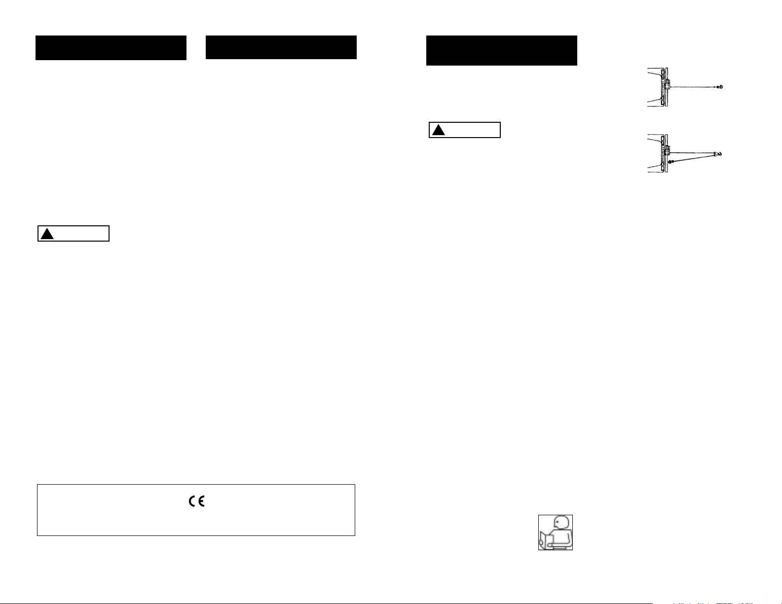
Figure 1
Freespool Clutch
In-Drum Brake
Remote Switch
Receptacle
Permanent
Magnet Motor
GENERAL DESCRIPTION
Integrated Solenoids
32
Thank you for purchasing an S series winch from Superwinch. It has been designed and
manufactured to provide years of trouble-free operation. We hope you will be pleased
with its performance. If you are not, for any reason, please contact our Customer Service
Department: (860) 928-7787 USA; (1822) 614101 England.
When requesting information or ordering replacement parts; always give the
following information:
1. Winch Part Number
2. Serial Number (found on housing)
3. Part Number (found in Replacement Parts List section)
4. Part Description
Please read and understand this Owner’s Manual before installing your winch. Pay particular
attention to the General Safety Information. Your winch is a very powerful machine. If used
unsafely or improperly, there is a possibility that property damage or personal injury could
result. We have included several features in the winch to minimize this possibility; however,
your safety ultimately depends on your caution when using this product.
The responsibility for safe operation of this winch ultimately rests with you, the operator.
Read and understand all safety precautions and operating instructions before installing
and operating the winch. Careless winch operation can result in serious injury and/or
property damage.
Throughout this manual, you will find notations with the following headings:
Indicates an imminently hazardous situation which, if not avoided,
will result in death or serious injury.
Indicates a potentially hazardous situation which, if not avoided,
could result in death or serious injury.
Indicates a potentially hazardous situation which, if not avoided,
may result in minor or moderate injury. This notation is also used
to alert against unsafe practices.
The following symbols on the product and in the Owner's manual are used:
Note
: Indicates additional information in the installation and operation procedures
of your winch.
Correct installation of your winch is a requirement for proper operation.
Please Note: The Superwinch S series winch is designed primarily for intermittent duty
general use. This winch is not designed to be used in industrial or hoisting applications
and Superwinch does not warrant it to be suitable for such use. Superwinch manufactures
a separate line of winches for industrial/commercial use. Please contact our Customer Service
Department for further information.
Congratulations on your choice!
INTRODUCTION
Roller Fairlead
ROLLING LOAD CAPACITIES
S4000
Working Load* . . . . . . . . . . . . . . . . . . . . . . . . . . . . . . . . . . . . . . . . . 4,000 lb. (1814 kg)
Wire Rope . . . . . . . . . . . . . . . . . . . . . . . . . . . . . . . . . . . . . . . . . . . . 7/32" x 60'
Motor . . . . . . . . . . . . . . . . . . . . . . . . . . 12V or 24VDC 1.8 hp (1.34 kW) peak
Gear Ratio . . . . . . . . . . . . . . . . . . . . . . . . . . . . . . . . . . . . . . . . . . . . . . . . 159:1
S5000
Working Load* . . . . . . . . . . . . . . . . . . . . . . . . . . . . . . . . . . . . . . . . . 5,000 lb. (2268 kg)
Wire Rope . . . . . . . . . . . . . . . . . . . . . . . . . . . . . . . . . . . . . . . . . . . . 1/4" x 50'
Motor . . . . . . . . . . . . . . . . . . . . . . . . . . 12V or 24VDC 2.1 hp (1.57 kW) peak
Gear Ratio . . . . . . . . . . . . . . . . . . . . . . . . . . . . . . . . . . . . . . . . . . . . . . . . 159:1
* Based on first layer performance
SPECIFICATIONS
S5000
S4000
Slope* 10% (6º) 20% (11º) 30% (17º) 100% (45º)
Lbs.**
kg**
17,588
7,978
11,905
5,400
9,138
4,145
4,499
2,041
Slope* 10% (6º) 20% (11º) 30% (17º) 100% (45º)
Lbs.**
kg**
22,613
10,257
15,306
6,943
11,749
5,329
5,784
2,624
Read Owner's
Manual
Always Use
Handsaver
Keep clear of winch,
wire rope and hook
while operating
Never use winch
to lift or move
people
Never use
winch to hold
loads in place
SAFETY PRECAUTIONS
DANGER
!
WARNING
!
CAUTION
!

Description Quantity
Winch assembly with wire rope including lead wires 1
Circuit breaker assembly with hardware 1
Handsaver 1
Mounting hardware kit 1
Remote pendant 1
Owner’s manual 1
This carton contains the following items. Please unpack carefully.
Read instructions before beginning.
UNPACKING
DIMENSIONS
S4000, S5000
Figure 2
PERFORMANCE
Wire Rope Max. Pulling Capacity
Layer lbs. kg
1 4,000 1814
2 3,000 1361
3 2,600 1179
4 2,000 907
Motor
Load Speed Current
lbs. kg ft/min m/min Amps
0 0 21.6 6.6 30
1,000 454 16.0 4.9 90
2,000 907 12.4 3.8 155
2,500 1134 10.6 3.2 180
3,000 1361 8.8 2.7 215
3,500 1588 6.2 1.9 250
4,000 1814 4.5 1.4 311
Wire Rope Max. Pulling Capacity
Layer lbs. kg
1 5,000 2268
2 4,000 1814
3 3,500 1588
4 2,900 1315
Motor
Load Speed Current
lbs. kg ft/min m/min Amps
0 0 17.5 5.3 36
1,000 454 14.5 4.4 80
2,000 907 12.0 3.7 135
3,000 1361 9.5 2.9 200
4,000 1814 7.3 2.2 265
5,000 2268 4.5 1.4 350
S4000
S5000
* Based on first layer performance
NOTES
1. All dimensions are in inches [millimeters].
2. Typical mount is to flat surface capable of handling the loads. Bolts to be Grade 5 or better.
6.0
(152)
15.1
(383)
7.2
(183)
7.1
(180)
3.1
(79)
5.9
(150)
3.69
(93.7)
1.24
(31.5)
ROLLER FAIRLEAD
SCREWS
DRUM SUPPORT
PLATE SCREWS
MOTOR
SCREWS
4 5
DRUM SUPPORT
PLATE
Your S series winch is a very powerful
machine. Treat it with respect, use it
with caution and always follow the
safety guidelines.
The wire rope
may break
before the winch stalls. For heavy
loads, use a pulley block to reduce
the load on the wire rope.
1. The S4000 and S5000 winch is
rated at 4,000 and 5,000 pounds
(1814 and 2268 kg) (single line)
capacity on the wire rope layer
closest to the drum. DO NOT
OVERLOAD. DO NOT ATTEMPT
PROLONGED PULLS AT HEAVY
LOADS. Do not maintain power
to the winch if the motor stalls.
Overloads can damage the winch
and/or the wire rope and create
unsafe operating conditions. FOR
LOADS OVER
2
/3RATED CAPACITY, WE RECOMMEND THE USE OF
THE OPTIONAL PULLEY BLOCK TO
DOUBLE LINE THE WIRE ROPE
(Figures 3 & 15). This reduces the
load on the winch and the strain
on the wire rope by approximately
50%. If attaching back to vehicle,
attach to the frame or other load
bearing part. The vehicle engine
should be running during winch
operation to minimize battery drain
and maximize winch power and
speed. If considerable winching is
performed with the engine off,
the battery may be too weak to
restart the engine.
2. AFTER READING AND UNDERSTANDING THIS MANUAL, LEARN
TO USE YOUR WINCH.
After installing the
winch, practice
using it so you
will be familiar with it when the
need arises.
3. DO NOT “move” your vehicle to
assist the winch in pulling the
load. The combination of the
winch and vehicle pulling together
could overload the wire rope and
the winch.
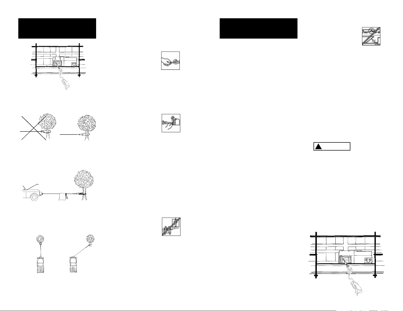
4. KEEP WINCHING AREA CLEAR. Do
not allow people to remain in the
area during winching operations.
ALWAYS STAND CLEAR OF WIRE
ROPE, HOOK AND WINCH. IN THE
UNLIKELY EVENT OF ANY COMPONENT FAILURE, IT IS BEST TO
BE OUT OF HARM‘S WAY.
5. INSPECT WIRE ROPE AND EQUIPMENT FREQUENTLY. A FRAYED
WIRE ROPE WITH BROKEN
STRANDS SHOULD BE REPLACED
IMMEDIATELY. Always replace
wire rope with the manufacturer‘s
identical replacement part (see
Replacement Parts List).
Periodically check the winch
installation to ensure that all
bolts are tight.
6. USE HEAVY LEATHER GLOVES
when handling wire rope. DO
NOT LET WIRE ROPE SLIDE
THROUGH YOUR HANDS EVEN
WHEN WEARING GLOVES.
WARNING
!
7
GENERAL SAFETY
INFORMATION
Figure 3
Single Line
Double Line
INTERMITTENT DUTY
An electric winch is like any other
motor driven power tool such as
an electric drill or saw. The electric
motor should not be allowed to
become excessively hot. Normal
precautions will extend the life
of your motor. Keep the duration
of pulls as short as possible.
If
the end of the motor becomes
uncomfortably hot to touch
,
stop winching and allow the
motor to cool down.
If the winch
motor stalls,
do not continue to apply power
to the winch.
6
FEATURES
Electric Motor – 1.8 (S4000),
2.1 (S5000) peak hp, 1.34 (S4000),
1.57 (S5000) kW) 12V or 24V
Permanent Magnet.
Braking – A wrap spring brake
which will hold 50% of rated load
on the first wrap. Reducing by
approximately 10% per layer
thereafter.
Drum – Die cast aluminum running
in maintenance free bearings.
Freespool Clutch – Operated by
an easy action lever which disengages the gearbox to allow the
wire rope to be pulled out without
using electric power. A tension
plate reduces backlash and snarling
when pulling out the wire rope.
Remote Switch – 30' (9.14 m)
handheld pendant switch assembly
with toggle switch.
Mounting – Optional custom
engineered mounting kits are available
for vehicle frame attachment.
European Union
Noise The noise level of this winch in operation is below 92 dB(A).
Battery Isolator In order to conform to Machinery Directive 89/392/EEC, each machine installation must be
fitted with an Isolator (Part Number 8370) whereby the machine can be brought safely to a complete stop.
CAUTION
!
7. NEVER WINCH WITH LESS THAN
5 TURNS of wire rope AROUND
THE WINCH DRUM since the
wire rope end fastener will NOT
withstand a load. ALWAYS USE
THE HANDSAVER
when guiding the
wire rope in or
out (see Figure 4).
8. KEEP CLEAR OF WINCH, TAUT
WIRE ROPE AND HOOK WHEN
OPERATING WINCH. Never put
your finger through the hook. If
your finger should become
trapped in the hook, you could
lose your finger.
Never guide a wire
rope onto the drum
with your hand.
9. NEVER HOOK THE WIRE ROPE
BACK ONTO ITSELF because you
could damage the wire rope.
Use a nylon sling (Figure 5).
10. It is a good idea to lay a heavy
blanket or jacket over the wire
rope near the hook end when
pulling heavy loads (Figure 6). If
a wire rope failure should occur,
the cloth will act as a damper
and help prevent the rope from
whipping. Raise the hood of the
vehicle for added protection.
11. NEVER USE YOUR
WINCH FOR LIFTING
OR MOVING PEOPLE.
12. Your winch is not designed or
intended for overhead hoisting
operations.
13. AVOID CONTINUOUS PULLS
FROM EXTREME ANGLES as this
will cause the wire rope to pile
up at one end of the drum
(Figure 7). This can jam the wire
rope in the winch, causing damage
to the rope or the winch.
14. NEVER OBSCURE THE WARNING
INSTRUCTION LABELS.
15. Always operate winch with an
unobstructed view of the winching operation.
16. Equipment such as tackle, hooks,
pulley blocks, straps, etc. should
be sized to the winching task
and should be periodically
inspected for damage that could
reduce their strength.
17. NEVER RELEASE FREESPOOL
CLUTCH WHEN THERE IS A LOAD
ON THE WINCH.
18. STORE THE REMOTE PENDANT
ASSEMBLY IN A SAFE PLACE
when not in use to prevent use
by children or other unauthorized persons.
19. DO NOT OPERATE WINCH
WHEN UNDER THE INFLUENCE
OF DRUGS, ALCOHOL OR
MEDICATION.
20. ALWAYS UNPLUG THE REMOTE
PENDANT BEFORE WORKING IN
OR AROUND THE FAIRLEAD OR
WINCH DRUM (THE DANGER
ZONE) so that the winch cannot
be turned on accidentally.
21. When moving a load, slowly
take up the wire rope slack until
it becomes taut. Stop, recheck
all winching connections. Be
sure the hook is properly seated.
If a nylon sling is used, check the
attachment to the load.
22. When using your winch to move
a load, place the vehicle transmission in neutral, set vehicle parking brake and chock all wheels.
23. DO NOT USE THE WINCH TO
HOLD LOADS IN PLACE.
Use other means of securing
loads such as tie down straps.
Superwinch offers a
wide variety of tie
downs. Contact your
local Superwinch
dealer.
24. USE ONLY FACTORY APPROVED
SWITCHES, REMOTE CONTROLS
AND ACCESSORIES. Use of nonfactory approved components
may cause injury or property
damage and could void your
warranty.
25. DO NOT MACHINE OR WELD
ANY PART OF THE WINCH. Such
alterations may weaken the
structural integrity of the winch
and could void your warranty.
26. Do not power the winch out for
more than 50 feet (15.2m) or
longer than 2 minutes.
The drum
and wire rope
may get very hot (Figure 8).
27. DO NOT CONNECT WINCH TO
EITHER 110V AC HOUSE CURRENT OR 220V MAINS AS WINCH
BURNOUT OR FATAL SHOCK
MAY OCCUR!
28. Never allow shock loads to be
applied to winch or wire rope.
29. Use caution when pulling or
lowering a load up and down a
ramp or incline. Keep people,
pets and property clear of the
path of the load.
GENERAL SAFETY
INFORMATION
(CONT.)
Figure 8
9
8
GENERAL SAFETY
INFORMATION
(CONT.)
Wrong Right
Right
Wrong
Figure 7
Figure 5
Figure 6
Figure 4
HOT!
WARNING
!

MOUN T I N G
YOU R WINCH
Superwinch mounting (fitting) kits
are available for most popular vehicles. If you can‘t locate a kit locally
contact Superwinch at the address
listed on the front of this manual
for the name of a Superwinch dealer
near you.
Detailed Mounting instructions are
provided with each mounting kit.
Read and follow directions carefully
to ensure proper winch alignment
and trouble free operation.
WARNING
!
ed with the wire rope in the underwind direction. Improper mounting
could damage your winch and void
your warranty.
DRUM SUPPORT
PLATE SCREWS
6.0
(152)
This winch
MUST be mou
nt-
I N S TA L L AT I O N
MINIMUM ELECTRICAL
REQUIREMENTS
For 12 volt winches, a 60 ampere
alternator and battery with 440
cold-cranking amperes capacity are
the minimum recommended power
sources. If the winch is in heavy use,
an auxiliary battery and heavy duty
alternator are recommended.
Step (1)
Install mounting kit or structural
s
upport for winch.
Step (2)
When mounting the winch, pull the
freespool clutch lever into the freespool
position. Unwind 25-30 feet of rope
from the drum. This will provide the
access needed to install the mounting
bolts into the base plate mounting holes.
Mount the winch to the mount that
you have designed. Mounting bolts
supplied are the
correct length for
use with up to a
1/4”(6.3 mm)
thick plate.
strength grade weaker than
grade 5.
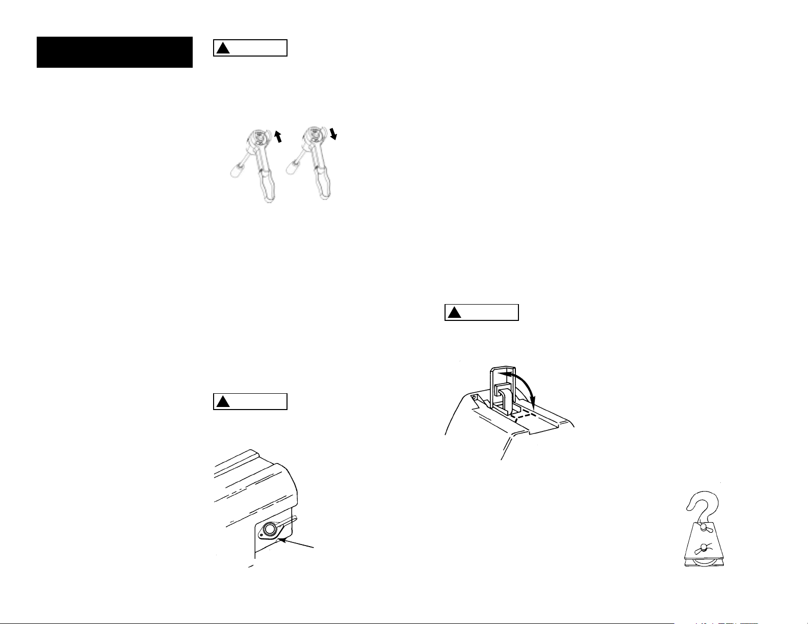
When attaching wires to the motor
terminals and solenoid (relay), hold
the inner nut when tightening the
outer nut. Do not allow the motor
terminals to rotate for it may cause
internal wire breakage or part misalignment. Be especially careful in
preventing the solenoid (relay)
terminals from rotating. Any
rotation can damage the solenoid
(see Figure 10).
Figure 10
Step (3)
Disconnect the vehicle battery
leads.
I N S TA L L AT I O N
C O N T.
WARNING
!
Do not substitute any
DANGER
!
contain gasses which are flammable
and explosive. Wear eye protection
during installation and remove all
metal jewelry. Do not lean over
battery while making connections.
Figure 11
Automobile
batteries
Be Prepared
Step (4)
Route the two (2) wires through
the vehicle grille to the battery. To
ensure against insulation abrasion
and/or cutting, apply several layers
of electrical tape where wiring may
come in contact with sharp metal
parts of the vehicle. Attach the circuit breaker assembly to the end of
the red wire. Wrap the circuit
breaker assembly with electrical tape
to prevent accidental short circuits.
Attach other end of circuit breaker
assembly to battery positive terminal.
ROLLER FAIRLEAD
SCREWS
Figure 9
1.24
(31.5)
3.69
(93.7)
5.9
(150)
3.1
(79)
7.1
NOTES
1. All dimensions are in inches [millimeters].
2. Typical mount is to flat surface capable of handling the loads. Bolts to be Grade 5 or better.
(180)
15.1
(383)
DRUM SUPPORT
PLATE
MOTOR
SCREWS
7.2
(183)
10
11
PULLING OUT THE WIRE ROPE
The wire rope has been installed on
your winch under minimal load at
the factory. The wire rope must be
respooled onto the drum under
load so that the outer layers will
not draw down into the inner ones,
thereby damaging the wire rope.
Lift the clutch lever to the “Free”
position as shown in Figure 13. If
there is a load on the wire rope,
the clutch lever may not turn easily.
DO NOT FORCE THE CLUTCH LEVER.
Release tension on the wire rope
by jogging out some of the wire
rope. Releasing the clutch and pull
out the wire rope and secure to
anchor or load. Check that there
are at least five (5) turns of wire
rope left on the drum. Re-engage
the drum by returning the clutch
lever to the “Engaged” position
(see Figure 14).
Lever must
be in the
“Engaged” position and locked
before winching.
TIPS FOR EXTENDING THE LIFE OF
YOUR WINCH
1. KEEP THE WIRE ROPE TIGHTLY
WOUND ON THE DRUM. Do not
allow the wire rope to become
loosely wound. A loosely-wound
spool allows a wire rope under
load to work its way down into
the layers of wire rope on the
drum. When this happens, the
wire rope may become wedged
within the body of the windings
damaging the wire rope. To prevent this problem, keep the wire
rope tightly and evenly wound
on the drum at all times. A good
practice is to rewind the wire
rope under tension after each
use. One way to do this is to
attach the hook to a stationary
object at the top of a gradual
incline and winch your vehicle
up the incline.
2. DO NOT ALLOW WINCH MOTOR
TO OVERHEAT. Remember, the
winch is for intermittent use only.
During long or heavy pulls the
motor will get hot. For pulling
at rated capacity, allow motor
to cool after 20 seconds of “On”
time. At loads less than 50
% of
rated capacity, allow to cool after
2 minutes of “On” time. KEEP THE
ENGINE RUNNING TO RECHARGE
THE BATTERY during this break.
3. USE A PULLEY BLOCK FOR HEAVY
LOADS. To maximize winch and
wire rope life, use a pulley block
to double line heavier loads
(Figure 15).
13
Figure 14
FREE
ENGAGED
Figure 15
Note: If you choose to locate the
winch at a greater distance than
the wires provided will permit,
it may be necessary to purchase
a larger gauge wire to get the
best performance from your winch.
If the total length of additional
wire to be added to the system
exceeds 10' (3m), use a larger wire
gauge size.
Attach the circuit breaker directly
to the battery positive terminal,
and reattach the terminal to the
battery. If your vehicle is equipped
with side pole terminals, it may
be necessary to obtain auxiliary
side terminal bolts from your
localauto parts dealer to make
these connections.
Connect the remaining wire to the
battery negative terminal, and connect the terminal to the battery.
Step (5)
Lift the freespool clutch lever to
the “Free” position. Pull several
feet of wire rope off the drum.
Return the clutch lever back to
the “Engaged” position. Plug in
the remote pendant control. Press
the switch trigger to the “RopeOut” position momentarily to
check wire rope drum rotation and
direction. If the drum rotates in
the wrong direction, recheck your
wiring. The Handheld pendant
switch activates a solenoid that
activates power to the winch
motor. One solenoid is for “Rope
Out” motor direction and the
other is for the “Rope In” motor
direction (Fig. 12).
To prevent
unauthorized
use of the winch, remove pendant
control and store in a clean dry area
such as the glove box.
PENDANT OPERATION
The handheld pendant switch
activates a solenoid that activates
power to the winch motor. To connect the pendant control, remove
the cover on the plug receptacle
(Figure 13) and insert the plug
end of remote switch. The plug
on the pendant control cord is
keyed and will fit into the socket
only one way. The switch trigger
returns to the “Off” position when
released. To change direction,
move the toggle in the other
direction. (Fig.12)
The switch
assembly must
be kept free of dirt and moisture
to ensure safe operation.
12
INSTALLATION
CONT.
Figure 12
Cable In
Cable Out
A
B
DUST
COVER
Figure 13
CAUTION
!
CAUTION
!
CAUTION
!

HOT!
BRAKE OPERATION
Your S Series winch has a wrap
spring brake that stops and holds
loads up to 50
% rated capacity on
the first layer of wire rope closest
to drum.
Each additional layer of wire rope
reduces brake capacity approximately 10%. When powering the
winch in, the brake is disengaged
and does not become activated
until the motor is turned off and
the load tries to pull the wire rope
off the drum. When the winch is
powered out, as in releasing a load,
the brake is engaged and the motor
must over power the brake drag to
rotate the drum. Therefore, it is
normal for the winch to operate
faster in one direction than the
other. The brake is designed for the
wire rope to be used in the underwind position only. DO NOT OVERWIND. Powering against the brake
will cause heat to build up in the
drum and may transfer heat to the
wire rope (Figure 19). DO NOT
POWER OUT FOR MORE THAN 50
FEET (15.2m) OR 2 MINUTES.
The drum and
wire rope may
get very hot.
When wire rope is removed from
the drum, as in bringing the hook
to the load, the freewheel feature
of the winch should be used.
WARNING
!
15
Figure 19
4. The pull required to start a load
moving is often much greater
than the pull required to keep
it moving. AVOID FREQUENT
STOPS AND STARTS during pull.
5. PREVENT KINKS BEFORE THEY
OCCUR.
a. This is the start of a kink. At
this time, the wire rope should
be straightened.
b. The wire rope was pulled and
the loop has tightened to a
kink. The wire rope is now permanently damaged and must
be replaced.
c. Kinking causes the wire strands
under the greatest tension to
break and thus reduces the
load capacity of the wire rope.
The wire rope must be replaced.
6. EQUIPPING THE WINCH WITH A
ROLLER FAIRLEAD will substantially
reduce wear on the wire rope
during angle pulls (Figure 17).
The rollers eliminate heavy rubbing and abrasion to the wire rope.
Periodically check tightness of
mounting bolts and electrical connections. Remove any dirt or corrosion that may have accumulated
on the electrical connections.
Repair should be done by
Authorized Superwinch Repair
Centers ONLY. Do not attempt
to disassemble the gearbox.
Disassembly will void warranty.
LUBRICATION
The gearbox and drum bearing are
permanently lubricated with a high
performance gear lube. If relubrication is necessary (after repair or
disassembly) only use Shell Alvenia
EP2 or equivalent.
REPLACING THE WIRE ROPE
Never substitute a heavier or lighter
wire rope. Never use rope made of
any material other than wire.
Always replace damaged wire
rope with manufacturer’s identi-
cal replacement part
(see
Replacement Parts list). Pass attaching end of wire rope through the
fairlead (if equipped) and attach it
to the drum. When inserting the
wire rope into the drum, insert it
into the correct end of the hole
provided (Figure 18). Tighten the
set screw securely.
It is important that the wire rope be
wound tightly onto the drum. A
good way to do this is to attach the
wire rope hook to a fixed object at
the top of a slight incline, then
winch the vehicle up the incline.
14
MAINTENANCE
AND REPAIRS
Figure 16
a
b
c
Figure 17
Figure 18
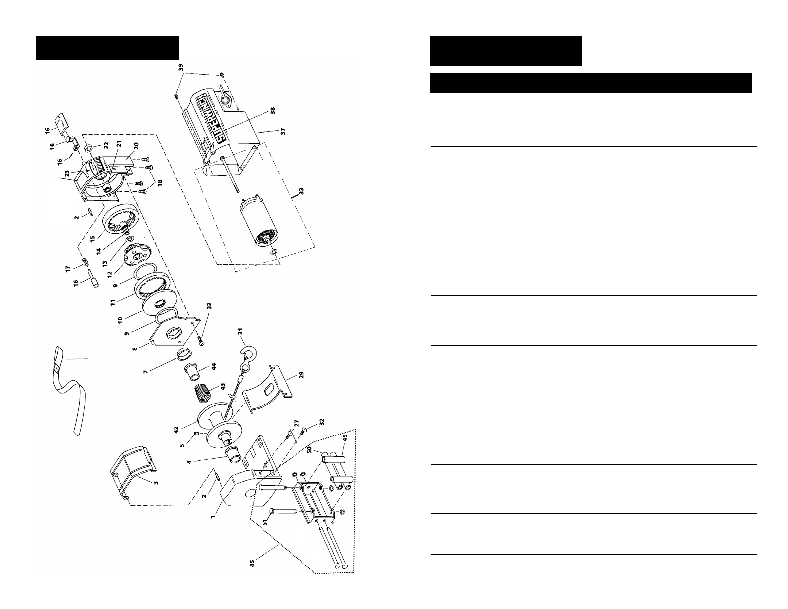
W INC H ASSEMBLY
REPLACEMEN T
PA R T S L I S T
Reference
5 M6 x 1 x 8mm Cup Pt. Set Screw 90-23164-12 1
52
Safety
(Includes Shaft, Lever, Handle, and Rivet)
18 M6 x 1 x 16mm Flat Head Screw 89-22291-01 4
20 Housing Assembly (includes 21 & 22) 89-40104 1
21 Needle Bearing (.8125 x 1.125 x .750) 89-23263-03 1
27 M6 x 1 x 13mm Button Head Screw 89-22290-01 2
30
31 Wire Rope Assembly w/hook 1/4"x50' (S5000) 1577A 1
Wire Rope Assembly w/hook 7/32"x60' (S4000) 1514A 1
32 M6 x 1 x 16mm Button Head Screw 89-22290-02 5
33 12 Volt Complete Motor (S5000) 90-33294 1
12 Volt Complete Motor (S4000) 90-33295 1
38 “Superwinch” 177222-98etalpemaN
39 M4 x 0.7 x 6mm Hex Washer Head Screw 89-22292-01 4
ytQrebmuN traPnoitpircseDrebmuN
112025-98esaB1
210-30332-98niP evoorG2
186223-98drauG elbaC3
186222-98gniraeB niaM4
196222-98gniraeB murD7
129004-98troppuS murD8
247521-09rehsaW tsurhT9
136223-98etalP evirD01
156223-98raeG gniR gnitatoR11
114122-98ylbmessA reirraC yratenalP21
130333-98raeG nuS41
166223-98raeG gniR yranoitatS51
108501-98tiK riapeR leehW eerF61
180-25132-09gnirpS leehW eerF71
120021-98gniraeB tfahS rotoM22
123371-98ogoL 0005S32
113371-98ogoL 0004S
159223-98gnirpS noisneT elbaC92
102113-78 revasdnaH03
189233-98 rotoM etelpmoC tloV 42
181333-09rotoM etelpmoC tloV 42
142025-98revoC rotoM73
158004-98 murD24
124322-98gnirpS ekarB34
178222-98retpadA ekarB44
12235daelriaF relloR54
16
240-86521-09relloR 253.2 x 8/594
260-86521-09relloR 537.4 x 8/505
210-43322-98)trohS( tfahS daelriaF relloR15
103302-98lebaL ytefaS25
17

53
58
61
54
55
57
59
60
62
63
19
REPLACEMENT
PARTS LIST
Reference
Number Description Part Number Qty
TORQUE SPECIFICATIONS
Drum Support Plate 50-60 lb in
Screws
Hawse (Roller Fairlead) 45-55 lb in
Screws
Base Screws 65-75 lb in
Motor 35-40 lb in
TORQUE SPECIFICATIONS
Over torquing
could damage
your winch and void your warranty.
WARNING
!
53 Leadwire spacer kit 89-24430 1
54 Buss bar kit 89-24431 1
55 Black 2 gage wire (-), S5000 12V 89-22635-61 1
Black 6 gage wire (-), S4000, S5000 24V 89-23292-38 1
57 Band clamp 89-14459 2
58 Red 2 gage wire (+), S5000 12V 89-22635-60 1
Red 6 gage wire (+), S4000, S5000 24V 89-23292-37 1
59 Socket 90-14140 1
60 Type 6 solenoid with bracket, 12V 89-24429 1
Type 6 solenoid with bracket, 24V 89-24467 1
61 Handheld remote control 90-33450-02 1
62 Ground jumper wire 18 gage 89-23283 1
63 Terminal adapter 89-14458 1
18
ROLLER FAIRLEAD
SCREWS
MOTOR
SCREWS
DRUM SUPPORT
PLATE SCREWS
DRUM SUPPORT
PLATE SCREWS
SOLENOID ASSEMBLY

Motor will not operate or
runs in one direction only
Winch will not shut off
Motor runs extremely hot
Motor runs but with
insufficient power or line
speed
Motor runs but drum
doesn’t turn
Winch runs backwards
Winch will not hold load
1. Damaged or stuck
solenoid
2. Switch inoperative
3. Broken wires or bad
connection
4. Damaged motor
5. Solenoids not grounded
1. Solenoid stuck “On”
1. Long period of operation
2. Damaged motor
3. Damaged brake
1. Weak battery
2. Battery to winch wire too
long
3. Poor battery connection
4. Poor ground
5. Damaged brake
1. Clutch not engaged
1. Motor wires reversed
2. Solenoids wired
incorrectly
1. Excessive load
2. Worn or damaged brake
1.
CAUTION Disengage
clutch before performing
this test to prevent powering the wire rope
drum. If a solenoid sticks
once, it is likely to stick
again and must be
replaced immediately.
Tap solenoid to free stuck
contacts. Check by applying voltage to the small
solenoid terminal. Be
sure solenoid is grounded
back to source. A solenoid that is not stuck will
make an audible “click”
when first energized.
2. Replace switch
3. Check for poor connections:
CAUTION Always use
2 wrenches (spanners)
(see Fig. 11)
4. Replace or repair motor
5. Check the ground path
between battery negative and solenoid base
1. If a solenoid sticks on,
reverse direction and
hold trigger switch until
the power lead can be
disconnected. A safety
disconnect switch is available as an accessory
1. Allow to cool
2. Replace or repair motor
3. Replace or repair brake
1.
Recharge or replace battery.
Check charging system
2. Use larger diameter wire
3. Check battery terminals
for corrosion. Clean as
required
4. Check and clean
connections
5. Repair or replace brake
1. Engage clutch
1. Recheck wiring
2. Recheck wiring
1. Reduce load or double
line
2. Repair or replace brake
Symptom Possible Cause(s) Corrective Action
USA
Superwinch Inc.
Winch Drive
Putnam, CT 06260
phone: 860-928-7787
repair@superwinch.com
Electric Motor Repair
2010 North 4th Street
Minneapolis, MN 55411
phone: 612-588-4693
Berens & Associates
124 Hegenberger Loop
Oakland, CA 94621
phone: 800-540-2858
berens94621@yahoo.com
Zorko’s Alternator Service
241 Wells Road
Home, PA 15747
phone: 800-468-5055
zasapw@microserve.net
Electric Motors of Iowa City
50 Commercial Court
Iowa City, IA 52246
phone: 319-354-4040
emic4040@aol.com
CANADA
Demand Electric
228-39th St. N.E.
Calgary, AB T2E 2M5
403-230-2709
Harold Supply
3 Southerland Ave.
Sudbury, Ont. P3C 3A7
705-761-4455
Explora Industries Ltd.
9605-5th Ave.
Edmonton, AB T6E 0B2
780-430-8591
Dayworth Sales
1 Saunders Rd. Unit 2
Barrie, Ont. 9A7 9A7
705-726-7778
Les Equipment Twin
10401 Parkway Blvd.
Ville D’Anjou, PQ H1J 1R4
514-353-1190
Buffalo Industries
251-253 Princess Street
Winnipeg, Manitoba R2C 1M1
204-942-1951
Power Plus Tool Repair
57 Millenium Ave.
Moncton, NB E1E 2G2
560-855-8665
Muskoka Auto Parts
11 King William St.
Huntsville, Ont. P1H 2K8
705-789-2321
Lou Dennis Auto
Hiway 11 South
Sundridge, Ont. P0A 1Z0
705-384-5345
Outdoors Plus
128 Regional St.
P.O. Box 1349
Port Aux Basques, NF A0M 1C0
709-695-7533
Bobcaygeon Auto and Marine
91 Main St.
Bobcaygeon, Ont. K0M 1A0
705-738-2317
MAP Bracebridge
19 Taylor Rd.
Bracebridge, Ont. P1L 1W3
705-645-8785
MAP Fenelon Falls
165 Lindsay St.
Fenelon Falls, Ont. K0M 1N0
705-887-6232
Central Electric Motor Rewind
#1-1960 Windsor Rd.
Kelowna, NC V1Y 2Y3
250-860-4415
jnelsoncentral@netscape.net
Delta Tool Repair Limited
114-7533, 135th St.
Surrey, BC V3W 0N6
604-591-3230
Ted's Power Tool Repair
426-44th St. East
Saskatoon, SK S7K OW1
306-934-6155
Bob's Electric Truck Servise
845-B Macdonald Ave.
Regina, SK S4N 2X5
306-721-4148
Off Road Canada
251-12th St. "B" North
Lethbridge, AB T1H 2K8
403-327-7722
Gary's Starter & Alternator
P.O.Box 7 Site 4
RR 1 Mount Uniacke B0N 1Z0
Contact: Gary Thorne
902-757-2388
Power Blitz Mftg. & Maintenance
577 Edgeley Blvd. Unit 6
Concord, Ont. L4K 4B2
905-669-8209
ali@powerblitz.com
Bruce's Recreaction
92 Balbo Dr.
Shoal Harbour Nfld A5A 4A8
709-466-3355
Atlantic Recreation & Marine
5 School St.
Sydney, Nova Scotia
B1S 3G1
902-567-1697
sbidart@thearm.ca
UNITED KINGDOM
Superwinch, LTD
Abbey Rise, Whitchurch road
Tavistock, Devon PL19 9DR
+44 (0) 1822 614101
WORLDWIDEContact your Local
Superwinch Distributor or call Superwinch.
21
WARRANTY REPAIR CENTERS
20
TROUBLESHOOTING CHART
If a problem arises, contact your nearest
Superwinch dealer or repair center.

L IMIT E D WARR ANTY
VALID WOR LDWIDE
LIMITED WARRANTY
Superwinch Inc. (“Seller”) warrants to the original buyer (“YOU”) all parts and components except
wire rope to be free of defects in materials and workmanship for a period of ONE (1) year from
provable date of purchase. Any Superwinch product which is defective will be repaired or replaced
without charge to you, upon compliance with these procedures. The warranties set forth herein
are exclusive and in lieu of all other warranties, whether oral or written, express or implied.
WARRANTY PERFORMANCE PROCEDURE
LIMITED
Upon discovery of a defective Superwinch product, you shall mail to the Seller at his factory or to
any Factory Authorized Service Center written notice of such defect and mail, ship or otherwise
deliver the defective Superwinch, postage or shipping prepaid. Repairs or replacements by Seller
under this Limited Warranty will normally be accomplished within fifteen (15) business days after
receipt of the defective Superwinch. Seller or its Authorized Agents may make reasonable charges
for parts and la
WARRANTY AND REMEDY LIMITATIONS AND EXCLUSIONS
Repair and/or replacement of the defective Superwinch or component part thereof as provided
herein is the exclusive remedy for you. The following exclusions or limitations of warranties and
limitations of remedies shall be expressly applicable:
A. Express Warranties. Seller Warrants that the Superwinch is as described in the ”Superwinch
Owner’s Manual” provided herewith; no other express warranty is made in respect to
Superwinch. If any model or sample was shown to you, such model or sample was used for illustrative purposes only, and shall not be construed as a warranty that the Superwinch will conform to
the sample or model. SELLER MAKES NO EXPRESS WARRANTY WITH RESPECT TO THE WIRE ROPE
INCORPORATED IN THE PRODUCT.
B. Implied Warranty. The implied warranty of merchantability and all other implied warranties
shall only extend from the provable date of purchase for one (1) year. The wire rope is sold
without any implied warranties. Some states within the U.S.A. do not allow limitations on how
long an implied warranty lasts, so the above limitation may not apply to you.
C. Incidental and Consequential Damages. SUBJECT TO THE SELLER’S LIMITED WARRANTY OBLIGATIONS SET FORTH HEREIN, SELLER SHALL NOT BE
ANY KIND, OR FOR CONSEQUENTIAL DAMAGES TO PROPERTY, LOSS OF PROFITS AND LOSS OF USE
WHICH MAY BE CAUSED BY ANY DEFECT IN, OR MALFUNCTION, OR FAILURE
SUPERWINCH. SOME STATES WITHIN THE USA DO NOT ALLOW THE EXCLUSION OR LIMITATION OF
INCIDENTAL OR CONSEQUENTIAL DAMAGES, SO THE ABOVE LIMITATION OR EXCLUSION MAY
NOT APPLY TO YOU.
D. Condition of Warranty. Seller shall not be required to comply with its warranty duties provided
herein if the defect, malfunction, or failure of the Superwinch was caused by damage (not resulting
from defective or malfunctioning components) or unreasonable use by you. Unreasonable use shall
include, but not be limited to, the failure to provide reasonable and necessary maintenance or
installation or use of the Superwinch without compliance with the instructions contained in the
Superwinch Owner’s Manual, and subjecting the Superwinch to loads in excess of the load listed in
the Owner’s Manual for the particular model number. Seller’s liability under this warranty or for any
loss or damage to the Superwinch product shall not exceed the
replacing the Superwinch product, and upon expiration of the warranty period, all such liability
shall terminate. The agents, dealers and employe
cations to this warranty, or additional warranties binding on the Seller. Accordingly, additional statements, whether oral or written, do not constitute warranties and should not be relied upon.
LEGAL REMEDIES OF BUYER
This Limited Warranty gives you specific legal rights, and you may also have other rights which
may vary from state to state within the USA and from country to country. You also have implied
warranty rights. In the event of a problem with Limited Warranty service or performance, you may
be abl
priate jurisdictions outside the USA.
INQUIRIES
Any inquiries regarding compliance with warranties provided herein may be addressed in writing
to: Superwinch Inc., Winch Drive, Putnam, CT 06260, USA or to: Superwinch Ltd., Abbey Rise,
Whitchurch Road, Tavistock, Devon PL 19 9DR, England.
bor for repairs not covered by this Limited Warranty.
the
”as is,”
RESPONSIBLE FOR INCIDENTAL DAMAGES OF
OF THE ENCLOSED
cost of correcting the defects in or
es of the Seller are not authorized to make modifi-
e to go to small claims court, a state court, or federal district court in the USA or to appro-
MANUAL DEL PROPIETARIO
INSTALACIÓN • OPERACIÓN • MANTENIMIENTO
PRECAUCIONES DE SEGURIDAD • PIEZAS DE
REPUESTO
S4000 y S5000
Cabrestantes Eléctrico de 12 y 24 Volts CD
Con control remoto
PRECAUCION
!
LEA Y ENTIENDA ESTE MANUAL ANTES
DE INSTALAR Y OPERAR SU PRODUCTO SUPERWINCH

Las especificaciones asumen un 10% de coeficiente de fricción.
* Una pendiente de 10% es una elevación de 30.48 cm en 3.048 m (1 ft en 10 ft). Arriba se muestra
una pendiente en grados aproximados.
** Todas las cargas mostradas son para operación de línea sencilla. La operación de línea doble
con el bloque de poleas opcional duplica aproximadamente la capacidad del cabrestante.
25
Figura 1
DESCRIPCIÓN GENERAL
24
Gracias por comprar un cabrestante Serie S de Superwinch. Éste ha sido diseñado y fabricado para proporcionar años de operación sin problemas. Esperamos que esté satisfecho con
su rendimiento. Si no lo está por cualquier motivo, por favor comuníquese con nuestro
Departamento de Servicio al Cliente al: (860) 928-7787 en E.U.A.; (1822) 614101 en Inglaterra.
Cuando solicite información o piezas de refacción, siempre dé la siguiente información:
1. Número de Pieza del cabrestante
2. Número de Serie (se encuentra en la carcasa)
3. Número de Pieza (se encuentra en la lista de piezas de este manual)
4. Descripción de la pieza
Por favor lea y entienda este manual del propietario antes de instalar su cabrestante. Ponga
particular atención a la Información General de Seguridad. Su es una máquina mu poderosa.
Si se usa sin precaución o inadecuadamente existe la posibilidad de causar daños a la propiedad
o lesiones personales. Hemos incluido varias características en el malacate para reducir esta
posibilidad. No obstante, su seguridad depende en última instancia en su pre caución al usar
este producto.
La responsabilidad de la operación segura de este cabrestante reside en última instancia en usted,
el operador. Lea y entienda todas las precauciones de seguridad e instrucciones de uso antes de
instalar y de utilizar el cabrestante. Si se lo utiliza sin precaución, podría ocasionar lesiones graves
y/o daños materiales.
En este manual, encontrará notas con los títulos siguientes:
Indica una situación de peligro inminente que, de no evitarse,
dará como resultado muerte o lesiones graves.
Indica una situación de peligro potencial que, de no evitarse,
podría dar como resultado muerte o lesiones graves.
Indica una situación de peligro potencial que, de no evitarse,
puededar como resultado lesiones leves o moderadas. Esta nota
se utiliza también para alertarle sobre prácticas inseguras.
Se usan los siguientes símbolos en el producto y en el Manual del Propietario:
Nota: Indica información adicional en los procedimientos de instalación y operación de su
cabrestante.
La instalación correcta de su cabrestante es un requisito para su operación correcta. Si
piensa instalar su cabrestante en el extremo delantero de su vehículo, use el juego de
montaje (adaptación) que ha sido diseñado y manufacturado por Superwinch para
recibir su malacate y adaptarse a su vehículo.
Por favor tome nota: El cabrestante Serie S de Superwinch está diseñado esencialmente
para uso general intermitente. Este cabrestante no está diseñado para usarse en aplicaciones industriales ni de grúa ni Superwinch garantiza que sea idóneo para tal uso.
Superwinch fabrica una línea separada de cabrestantes para uso industrial y comercial. Para
mayor información, por favor comuníquese con nuestro Departamento de Servicio al Cliente.
¡Felicidades por su elección!
INTRODUCCIÓ N
Embrague
Freno
Receptáculo del
Conmutador
Remoto
Moteur con Imán
Permanente
Solenoides Integrados
Guia de entrada
con rodillos
S4000
Carga de trabajo* . . . . . . . . . . . . . . . . . . . . . . . . . . . . . . . . . . . . . . . 4,000 lb. (1814 kg)
Cable de alambre . . . . . . . . . . . . . . . . . . . . . . . . . . . . . . . . . . . . . . 7/32" x 60'
Motor . . . . . . . . . . . . . . . . . . . . . . . . . . 12V or 24VDC 1.8 hp (1.34 kW) peak
Relación de engranes . . . . . . . . . . . . . . . . . . . . . . . . . . . . . . . . . . . . . . . 159:1
S5000
Carga de trabajo* . . . . . . . . . . . . . . . . . . . . . . . . . . . . . . . . . . . . . . . 5,000 lb. (2268 kg)
Cable de alambre . . . . . . . . . . . . . . . . . . . . . . . . . . . . . . . . . . . . . . . 1/4" x 50'
Motor . . . . . . . . . . . . . . . . . . . . . . . . . . 12V or 24VDC 2.1 hp (1.57 kW) peak
Relación de engranes . . . . . . . . . . . . . . . . . . . . . . . . . . . . . . . . . . . . . . . 159:1
*Basado en el rendimiento de la primera capa
SPECIFICATIONS
CAPACIDADES DE CARGA RODANTE
S5000
S4000
Slope* 10% (6º) 20% (11º) 30% (17º) 100% (45º)
Lbs.**
kg**
17,588
7,978
11,905
5,400
9,138
4,145
4,499
2,041
Slope* 10% (6º) 20% (11º) 30% (17º) 100% (45º)
Lbs.**
kg**
22,613
10,257
15,306
6,943
11,749
5,329
5,784
2,624
PELIGRO
!
ADVERTENCIA
!
PRECAUCION
!
Leer el Manual
del Propietario
Siempre use la
barra protectora
para manos
Manténgase alejado
del cabrestante, el
cable de alambre y
el gancho durante
la operación
Nunca use el
cabrestante para
levantar o mover
personas
Nunca use el
cabrestante para
sostener cargas
PRECAUCIONES DE
SEGURIDAD

Descripción Cantidad
Embrague de Carrete Libre 1
Solenoides Integrados 1
Motor de Imán Permanente 1
Receptáculo del interruptor Remoto 1
Freno de Tambor Interno 1
Manual del propietario 1
Esta caja contiene los siguientes artículos. Por favor desempáquelos
cuidadosamente. Lea las instrucciones antes de comenzar.
DISEMPACADO
DIMENSIONES
S4000, S5000
RENDIMIENTO
*Basado en el rendimiento de la primera capa
Capa del Capacidad Máxima de Tiro
Cable lbs. kg
1 4,000 1814
2 3,000 1361
3 2,600 1179
4 2,000 907
Carga Corriente
Velocidad del Motor
lbs. kg pies/min m/min Amperes
0 0 21.6 6.6 30
1,000 454 16.0 4.9 90
2,000 907 12.4 3.8 155
2,500 1134 10.6 3.2 180
3,000 1361 8.8 2.7 215
3,500 1588 6.2 1.9 250
4,000 1814 4.5 1.4 311
Capa del Capacidad Máxima de Tiro
Cable lbs. kg
1 5,000 2268
2 4,000 1814
3 3,500 1588
4 2,900 1315
Carga Corriente
Velocidad del Motor
lbs. kg pies/min m/min Amperes
0 0 17.5 5.3 36
1,000 454 14.5 4.4 80
2,000 907 12.0 3.7 135
3,000 1361 9.5 2.9 200
4,000 1814 7.3 2.2 265
5,000 2268 4.5 1.4 350
S4000
S5000
26 27
NOTAS:
1. Todas las dimensiones están en pulgadas [milímetros].
2. La instalación típica se realiza sobre una superficie plana capaz de soportar las cargas. Los pernos
deben ser Grado 5 o mejores.
6.0
(152)
15.1
(383)
7.2
(183)
7.1
(180)
3.1
(79)
5.9
(150)
3.69
(93.7)
1.24
(31.5)
Tornillos de la base
Tornillos
del escobén
(Guía de rodillos)
Tornillos de la placa
base del tambor
Tornillos del motor
Figura 2

2. DESPUÉS DE LEER Y ENTENDER
ESTE MANUAL, APRENDA A USAR
SU CABRESTANTE.Después de
instalar el cabrestante, practique
usándolo para que esté
familiarizarse con su
operación cuando surja
la necesidad de usarlo.
3. NO «mueva» su vehículo para
ayudar al cabrestante a tirar de la
carga. La combinación del
cabrestante y el vehículo tirando
a la vez puede sobrecargar el
cable de alambre y el cabrestante.
4. MANTENGA EL ÁREA DE MANIOBRAS LIBRE DE OBSTRUCCIONES.
No permita que permanezcan
personas en el área durante las
operaciones de tirado. SIEMPRE
MANTÉNGASE ALEJADO DEL
CABLE, EL GANCHO Y EL
CABRESTANTE. EN EL REMOTO
CASO DE FALLA DE CUALQUIER
COMPONENTE, ES MEJOR ESTAR
LEJOS DEL PELIGRO.
5. INSPECCIONE FRECUENTEMENTE
EL CABLE DE ALAMBRE Y EL
EQUIPO. UN CABLE DE ALAMBRE
DESHILACHADO CON HILOS
ROTOS DEBE REEMPLAZARSE
INMEDIATAMENTE. Siempre
reemplace el cable de alambre
con la pieza de repuesto del fabricante idéntica (vea la lista de
piezas). Revise periódicamente la
instalación del Cabrestante para
asegurarse de que los tornillos
estén firmes.
6. USE GUANTES DE CUERO PESADOS AL manejar el cable. NO
DEJE QUE EL CABLE DE ALAMBRE
SE DESLICE EN SUS MANOS NI
AÚN CUADO USE GUANTES.
29
INFORMACIÓN GENERAL
DE SEGURIDAD
Figura 3
Un sólo cable
Cable doble
28
SERVICIO INTERMITENTE
Un cualquier otra herramienta
motorizada, como por ejemplo un
taladro o una sierra eléctrica. No se
debe permitir que el motor eléctrico se caliente excesivamente. Las
precauciones normales extenderán
la vida de su motor. Mantenga la
duración de los tiros tan breve
como sea posible.
Si el extremo
del motor se calienta de modo
que resulte incómodo tocarlo
,
deje de operar el cabrestante y permita que el motor se enfríe.
Si el motor del
cabrestante se
para, no siga aplicándole energía al
cabrestante.
Unión Europea
Ruido El nivel de ruido de este cabrestante en operación está por debajo de los 92 dB. (A).
Aislante de la Batería Para cumplir con la Directiva de Maquinaria 89/392/EEC, todas las instalaciones de
máquinas deben estar equipadas con un aislante (Número de pieza 8370) con la cual la máquina puede detenerse
completamente con seguridad.
Motor Eléctrico - 1.8 (S4000), 2.1
(S5000) hp, 1.34 (S4000), 1.57
(S5000) kW) pico, con imán
permanente de 12 V ó 24 V.
Freno - Un freno de resorte para
el enrollamiento, que mantendrá
el 50% de la carga nominal en la
primera vuelta. A partir de ese
momento, ese porcentaje se
reducirá en aproximadamente
el 10% por cada capa.
Tambor – De aluminio fundido
sostenido por rodamientos sin mantenimiento.
Embrague de carrete libre –
Operado por una palanca de acción
fácil que desembraga el motoreductor para permitir que el cable de
alambre sea sacado sin usar corriente eléctrica. Una placa de tensión
reduce el latigueo y el tironeo
cuando se tira del cable de alambre.
Interruptor Remoto – 9.14 m (30')
Conjunto de interruptor de mano
tipo pendiente con interruptor
de reversa con interbloqueo y
disparador.
Montaje – Se ofrecen juegos de
montaje opcionales, diseñados a la
medida, para instalaciones sobre el
chasís del vehículo.
Un cabrestante eléctrico es como
CARACTERÍ STICAS
Su cabrestante Serie S es una
máquina muy poderosa. Trátelo
con respeto, úselo con precaución
y siempre siga los lineamientos
de seguridad
.
El cable puede
romperse
antes de que el cabrestante entre
en pérdida. Para cargas pesadas use
un bloque de poleas para reducir la
carga sobre el cable de alambre.
1. El cabrestante S4000 y S5000 tiene
una capacidad nominal de 4,000 y
5,000 libras (1814 y 2268 kg) (en
línea sencilla) en la capa de cable
de alambre más cercana al tambor. NO LO SOBRECARGUE.
NO TRATE DE TIRAR CARGAS
PESADAS DE FORMA PROLONGADA. No mantenga encendido el
cabrestante si el motor entra en
pérdida. Las sobrecargas pueden
dañar el cabrestante o el cable de
alambre y causar condiciones de
operación inseguras. PARA CARGAS MAYORES DE 2/3 LA CAPACIDAD NOMINAL, RECOMENDAMOS EL USO DEL BLOQUE DE
POLEAS OPCIONAL PARA LA
OPERACIÓN DEL CABLE DE
ALAMBRE EN LÍNEA DOBLE
(Figuras 3 y 15). Esto reduce la
carga sobre en el cabrestante y el
esfuerzo sobre el cable de alambre en aproximadamente el 50%.
Si lo monta en la parte trasera del
vehículo, sujételo al chasís u otra
parte que soporte carga. El motor
del vehículo debe estar funcionando durante la operación del
cabrestante para reducir el desgaste de la batería y aumentar la
potencia y velocidad del
cabrestante. Si se activa el
cabrestante durante considerables
periodos de tiempo con el motor
apagado, la batería podría descargarse demasiado, de modo que ya
no pueda arrancar el motor.
ADVERTENCIA
!
PRECAUCION
!

chos, bloques de poleas, cintas, etc.,
deben ser del tamaño de la tarea
de levantamiento y debe inspeccionar periódicamente que no tengan daños que puedan reducir su
resistencia.
17. NUNCA SUELTE EL EMBRAGUE DEL
CARRETE LIBRE CON UNA CARGA
EN EL CABRESTANTE.
18. ALMACENE EL CONJUNTO DE PEN-
DIENTE REMOTO EN UN LUGAR
SEGURO cuando no se use para evitar que lo usen los niños u otras personas no autorizadas.
19. NO OPERE EL CABRESTANTE CUAN-
DO ESTÉ BAJO LA INFLUENCIA DE
DROGAS, ALCOHOL
O MEDICAMENTOS.
20. SIEMPRE DESCONECTE EL PENDI-
ENTE REMOTO ANTES DE TRABAJAR
EN LA GUÍA DE RODILLOS Y EL
TAMBOR DEL CABRESTANTE O A SU
ALREDEDOR (LA ZONA DE
PELIGRO), para que no se pueda
encender el cabrestante
accidentalmente.
21. Cuando mueva una carga, recoja el
exceso de cable de alambre con
cuidado hasta que el cable de alambre esté tenso. Deténgase, vuelva a
verificar todas las conexiones de levantado. Asegúrese de que el gancho
esté bien asentado. Si se usa una
eslinga de nilón, revise la sujeción
a la carga.
22. Cuando use su cabrestante para
mover una carga, coloque la transmisión de su vehículo en neutral,
ponga el freno de mano y bloquee
todas las ruedas.
23. NO USE EL CABRESTANTE PARA
RETENER CARGAS EN UN SÓLO
SITIO. Use otros medios para asegurar cargas, como tirantes para atar.
Superwinch ofrece una
amplia variedad de ataduras.
Comuníquese con su distribuidor local Superwinch.
24. SÓLO USE INTERRUPTORES, CONTROLES REMOTOS Y ACCESORIOS
APROBADOS POR LA FÁBRICA. El
uso de componentes no aprobados
por la fábrica puede ocasionar
lesiones o daños a la propiedad, y
puede anular su garantía
25. NO MAQUINE NI SUELDE PARTE
ALGUNA DEL CABRESTANTE. Tales
alteraciones pueden debilitar la
integridad estructural del
cabrestante y pueden anular la
garantía.
26. No saque el cable con el motor del
cabrestante en longitudes mayores
de 15.2 metros (50 pies) o durante
periodos mayores de 2 minutos.
El tambor
y el cable
pueden calentarse mucho
(Figura 8).
27. NO CONECTE EL CABRESTANTE A
LA CORRIENTE RESIDENCIAL DE 110
VCA O DE 220 VCA, YA QUE SE
PUEDE QUEMAR EL CABRESTANTE
O ¡RECIBIR UN CHOQUE ELÉCTRICO
FATAL!
28. Nunca permita que se apliquen cargas de choque al cabrestante o al
cable de alambre.
29. Tenga precación al bajar o tirar de
una carga hacia arriba o hacia
abajo por una rampa o pendiente.
Mantenga a la gente, mascotas y
bienes lejos del camino de la carga.
ADVERTENCIA
!
31
INFORMACIÓN GENERAL
DE SEGURIDAD
(CONT.)
7. NUNCA USE EL CABRESTANTE CON
MENOS DE 5 VUELTAS de cable de
alambre en el tambor, ya que es
posible que el cable de alambre y su
sujeción no resistan la carga completa. Siempre use la barra para manos
cuando guíe el cable de
alambre hacia adentro o
afuera (ver la Figura 4).
8. MANTÉNGASE ALEJADO DEL
CABRESTANTE, EL CABLE TENSO Y
EL GANCHO AL OPERAR EL
CABRESTANTE. Nunca introduzca su
dedo a través del gancho. Si su dedo
llega a quedar atrapado en el gancho, podría perderlo.
Nunca guíe el cable hacia
el tambor con la mano.
9. NUNCA ENGANCHE EL CABLE DE
ALAMBRE SOBRE SÍ MISMO PORQUE
PODRÍA DAÑAR EL CABLE DE
ALAMBRE. Use una eslinga de nilón
(Figura 5).
10. Es una buena idea poner una frazada pesada o abrigo sobre el cable de
alambre cerca del extremo del gancho al tirar de cargas pesadas
(Figura 6). En el caso de que el cable
de alambre falle, la tela actuará
como atenuador para evitar que el
cable de alambre latiguee. Levante
la capota del motor del vehículo
para aumentar la protección.
11. NUNCA USE SU
CABRESTANTE PARA LEVANTAR O MOVER GENTE.
12. Su cabrestante no ha sido diseñado
para operaciones de izado.
13. EVITE TIRAR CONTINUAMENTE
DESDE ÁNGULOS EXTREMOS, ya
que esto causará que el cable de
alambre se apile en un extremo del
tambor (Figura 7). Esto puede atorar
el cable de alambre en el
cabrestante, dañando tanto el cable
de alambre como el cabrestante.
14. NUNCA TAPE LAS ETIQUETAS DE
INSTRUCCIONES DE ADVERTENCIA.
15. Siempre opere el cabrestante
teniendo una vista sin obstrucciones
del área de operaciones.
16. Los equipos como aparejos, gan-
30
INFORMACIÓN GENERAL
DE SEGURIDAD
(CONT.)
Incorrecto
Correcto
Figura 7
Figura 5
Figura 6
Figura 4
Correcto Incorrecto
Figura 8
¡
CALIENTE!

MONTAJE DE S U
CABRESTANTE
Se ofrecen juegos de montaje
(adaptación) de Superwinch para la
mayoría de los vehículos más populares. Si usted no puede localizar un
juego localmente, comuníquese con
Superwinch a la dirección anotada
al frente de este manual para
obtener el nombre del distribuidor
Superwinch más cercano.
Se proporcionan instrucciones detalladas de montaje con cada juego de
montaje. Lea y siga
las instrucciones cuidadosamente
para asegurar la alineación correcta
del cabrestante y su operación sin
problemas.
ADVERTENCIA
!
DEBE montarse con el cable en la
dirección de desenrollado por
abajo. El montaje indebido podría
dañar su cabrestante y anular su
garantía.
Tornillos de
la placa base
del tambor
6.0
(152)
Figura 9
Este
cabrestante
Tornillos
del escobén
(Guía de rodillos)
INSTALACI Ó N
REQUISITOS ELÉCTRICOS
MINIMOS
La capacidad mínima de las fuentes
de energía recomendadas para un
cabrestantes de 12 volts, es un alternador de 60 amperes y una batería
con 440 amperes de arranque en
frío. Si el cabrestante está sometido
a uso pesado, se recomienda utilizar una batería auxiliar y un alternador para servicio pesado.
Paso (1)
Instale el juego de montaje sobre el
apoyo estructural del cabrestante.
Paso (2)
Monte el cabrestante a la base que haya
longitud correcta para usarse con una
placa de hasta 1/4” (6.3mm).
15.1
(383)
Tornillos del motor
INSTALACI Ó N
(CONT. )
ADVERTENCIA
!
grado de resistencia menor a
grado 5.
Al conectar cables a las terminales
del motor y solenoides (relevador),
sostenga la tuerca interna al apretar la tuerca exterior. No permita
que giren las terminales del motor
porque puede romper los cables
internos o desalinear la pieza.
Tenga especial cuidado en evitar
que gire el solenoide (relevador)
Cualquier giro puede dañar el solenoide (vea la Figura 10).
Paso (3)
Desconecte los conductores de la
batería del vehículo.
No sustituya
por ningún
Figura 10
PELIGRO
!
contienen gases que son inflamables y explosivos. Use protección
para los ojos durante la instalación
y quítese toda la joyería de metal.
No se incline sobre la batería al
hacer las conexiones.
Figura 11
Las baterías de
los automóviles
Esté preparado
Paso (4)
Pase dos (2) cables a través de la
rejilla del vehículo a la batería. Para
proteger contra desgaste del aislamiento o cortes, aplique varias
capas de cinta aislante en lugares
donde el cableado pueda tocar
piezas agudas del vehículo. Ponga
el cortacircuitos en el extremo del
cable rojo. Envuelva el conjunto del
cortacircuitos con cinta aislante para
evitar cortocircuitos accidentales.
Conecte el otro extremo del conjunto
de interruptor de circuito al terminal
positivo de la batería.
1.24
(31.5)
3.69
(93.7)
5.9
(150)
7.1
3.1
(180)
(79)
NOTAS:
1. Todas las dimensiones están en pulgadas [milímetros].
2. La instalación típica se realiza sobre una superficie plana capaz de soportar las cargas. Los pernos
deben ser Grado 5 o mejores.
Tornillos de la base
7.2
(183)
32
33

35
CÓMO SACAR EL CABLE
El cable ha sido instalado en la
fábrica en su cabrestante bajo carga
mínima. El cable debe ser rebobinado al tambor bajo carga de modo
que las capas exteriores no se
inserten a las interiores, dañándose. Levante la palanca de
embrague a la posición «Free»
(Libre) como se muestra en la Figura
13. Si hay una carga en el cable de
alambre, es posible que la palanca
del embrague no gire fácilmente.
NO FUERCE LA PALANCA DE
EMBRAGUE. Suelte la tensión sobre
el cable, sacando lentamente un
poco de cable. Suelte el embrague,
saque el cable y asegúrelo al anclaje
o la carga. Revise que haya por lo
menos cinco (5) vueltas de cable de
alambre en el tambor. Vuelva a
embragar el tambor devolviendo la
palanca del embrague a la posición
de «Acoplado» (vea la Figura 14).
La palanca
debe estar en
la posición de «Acoplado» y estar
cerrada antes de operar el
cabrestante.
CONSEJOS PARA INCREMENTAR
LA VIDA ÚTIL DE SU CABRESTANTE
1. MANTENGA EL CABLE DE ALAMBRE ARROLLADO FIRMEMENTE
EN EL TAMBOR. No permita que
se afloje el cable de alambre. Un
carrete arrollado flojamente permite que el cable de alambre
tenso baje por las capas de cable
de alambre del tambor. Cuando
esto sucede, el cable de alambre
puede deformarse como cuña
dentro del cuerpo del enrollado
dañándose. Para evitar este problema, mantenga siempre el cable
de alambre embobinado firme y
uniformemente en . Una buena
práctica es enrollarlo bajo tensión
después de cada uso. Una manera
de hacerlo es sujetar el gancho a
un objeto estacionario hasta arriba de una pendiente gradual y
tirar de su vehículo hacia arriba
en la pendiente.
2. NO PERMITA QUE EL MOTOR
DEL CABRESTANTE SE SOBRECALIENTE. Recuerde, el cabrestante
se ha diseñado usarse sólo intermitentemente. Durante sesiones
de tirado largas o pesadas, el
motor se calentará. Para tirar a la
capacidad nominal, deje enfriar
el motor después de 20 segundos
de estar conectado (On). Para
cargas menores del 50% de la
capacidad nominal, deje enfriar
después de 2 minutos de estar
conectado (On).
3. USE UN BLOQUE DE POLEAS
PARA CARGAS PESADAS. Para
aumentar la vida del cabrestante
y del cabe de alambre, use un
bloque de poleas para tirar con
línea doble las cargas más
pesadas. (Figura 15)
PRECAUCION
!
Figura 14
LIBRE
ACOPLADO
34
Nota: Si decide ubicar el cabrestante
a una distancia mayor que la que
permiten los cables provistos, quizás
sea necesario comprar cable más
grueso para lograr el mejor
rendimiento de su cabrestante. Si la
longitud total del cable adicional a
conectar al sistema excede los 3.04
m (10'), use un cable de mayor calibre.
Conecte el interruptor directamente
a la terminal positiva de la batería,
y reconecte la terminal a la batería.
Si su vehículo está equipado con
terminales laterales quizás sea necesario obtener pernos para terminales laterales de su refaccionaria
local para hacer estas conexiones.
Conecte el otro cable a la terminal
negativa de la batería, y conecte la
terminal a la batería.
Paso(5)
Cambie la posición de la palanca del
embrague a la posición «Free»
(Libre). Saque varios pies de cable
de alambre del tambor. Coloque
nuevamente la palanca del
embrague en posición «Engaged»
(Trabado). Enchufe el control de
pendiente remoto. Presione
momentáneamente el obturador
del interruptor hacia la posición de
“Cable Afuera” para verificar la
rotación y dirección del tambor con
cable metálico. Si el tambor rota en
la dirección equivocada, revise nuevamente la instalación de los cables.
El interruptor pendiente de mano
activa un solenoide que le aplica
corriente al motor del cabrestante.
Un solenoide es para la dirección
«Rope Out» (Sacar Cable) del motor
y el otro es para la dirección «Rope
In» (Tirar Cable)(Fig. 12).
Para evitar el
uso no autorizado del cabrestante, quite el control
pendiente y almacénelo en un lugar
limpio y seco, como la guantera.
OPERACIÓN DEL PENDIENTE
El gatillo interruptor vuelve a la
posición «Off» (Apagado) cuando se
suelta (Figura 12, Artículo A). El
botón deslizante del reverso del
interruptor determina la dirección
de giro del tambor para funcionar
tirando o sacando cable (Figura 12,
Artículo B). El interruptor deslizador
está dotado de un sistema de
interbloqueo para que el motor no
pueda ponerse en marcha atrás si se
oprime el gatillo. Para cambiar la
dirección, suelte el gatillo, mueva el
botón deslizante y vuelva a oprimir
el gatillo. (Fig. 12)
El conjunto
del interruptor
debe mantenerse libre de tierra
y humedad para asegurar su
operación segura.
Para conectar el control de pendiente, levante la tapa guardapolvos
del receptáculo del enchufe (Vea la
Figura 13). La clavija del control de
pendiente está codificada y entrará
en el enchufe solamente en una
dirección.
PRECAUCION
!
PRECAUCION
!
INSTALACIÓ N
(CONT.)
TAPA
ANTI-POLVO
Figure 13
Figura 15
Cable hacia adentro
Cable hacia afuera
Figure 12

erlo es sujetar el gancho del cable
de alambre a un punto fijo en una
pendiente ligera y arrollarlo tirando
del vehículo.
OPERACIÓN DEL FRENO
Su cabrestante Serie S posee un
freno de resorte para el enrollamiento, que detiene y mantiene
cargas de hasta el 50% de la
capacidad nominal en la primera
capa de cable de alambre más cercana al tambor. Cada capa adicional
de cable de alambre redecirá la
capacidad de frenado en 10%
aproximadamente. Al arrollar el
cable con el motor, el freno no está
acoplado y no se activa sino hasta
que se apaga el motor y la carga
trata de tirar del cable hacia afuera
del tambor. Cuando se apaga el
cabrestante, como al soltar una
carga, el freno se acopla y el motor
deberá sobreponerse a la resistencia
del freno para girar el tambor. Por
lo tanto, es normal que el
cabrestante opere más rápidamente
en una dirección que en la otra. El
freno se ha diseñado para que el
cable se use sólo en la posición de
enrollado por debajo. NO lo enrolle
por encima. Tirar contra el resorte
hará que se acumule el calor y es
posible que éste se transmita al
cable de alambre (Figura 20). NO
SAQUE CABLE CON EL MOTOR POR
MÁS DE 15.2 METROS (50 PIES) O
POR 2 MINUTOS.
El tambor
y el cable de
alambre pueden calentarse mucho.
Cuando sale el cable de alambre del
tambor, como para llevar el gancho
a la carga, debe usarse la caracterís-
tica de rueda libre.
ADVERTENCIA
!
37
4. El tirón requerido para comenzar
a mover una carga a menudo es
mayor que el que se requiere
para mantenerla en movimiento.
EVITE PARADAS Y COMIENZOS
FRECUENTES DURANTE EL TIRO.
5. EVITE TORCEDURAS ANTES DE
QUE OCURRAN.
a. Este es el comienzo de una
torcedura. En este momento
debe enderezarse el cable de
alambre.
b. Se ha tirado del cable de alam-
bre y el rizo se ha apretado a
una retorcedura. Ahora el cable
de alambre ya está dañado permanentemente y debe ser
reemplazado.
c. Las torceduras hacen que se
rompan los hilos de alambre
bajo tensión y sí reducen la
capacidad de carga del cable
de alambre. El cable de alambre debe ser reemplazado.
6. EQUIPAR EL CABRESTANTE CON
UNA GUÍA DE ENTRADA CON
RODILLOS reduce sustancialmente
el desgaste del cable durante
sesiones de tirado en ángulo
(Figura 18). Los rodillos eliminan
el roce pesado y las abrasiones
sufridas por el cable.
Revise periódicamente la firmeza de
los tornillos de montaje y las conexiones eléctricas. Quite toda la tierra
o corrosión que se haya acumulado
en las conexiones eléctricas.
Las reparaciones deben hacerlas
los centros autorizados de
reparaciones Superwinch solamente. No trate de desarmar el
motoreductor. Si lo hace, anulará la garantía.
LUBRICACIÓN
La motoreductor y el cojinete del
tambor están lubricados permanentemente con un lubricante de
engranajes de alto rendimiento. Si
necesita volver a lubricarlo (luego
de una reparación o desarmado),
use Shell Alvenia EP2 o equivalente.
REEMPLAZAR DEL CABLE
Nunca sustituya por un cable de
mayor o menor capacidad. Nunca
use otro cable hecho de ningún
otro material que no sea alambre.
Siempre remplace el cable de
alambre con la pieza de refacción del fabricante idéntica
(vea
la lista de piezas). Pase el extremo
de sujeción del cable de alambre
por la guía de entrada (si está
equipado con ella) y sujételo al
tambor. Al insertar el cable de alambre al tambor, inserte el extremo
correcto al orificio provisto (Figura
19). Apriete bien el tornillo prisionero.
Es importante que el cable de alam-
bre esté firmemente arrollado al
tambor. Una buena manera de hac-
36
MANTENIMIENTO
Y REPARACIÓ N
Figura 16
a
b
c
Figura 17
Figura 18
Figura 19
¡
CALIENTE!

CONJUNTO DEL
CABRESTANTE
52
Seguridad
30
LISTA DE PIEZAS
DE REPUESTO
Nú Ned orem úmero
Referencia Descripció .tnaCazeiP edn
5 Tornillo prisionero de punta redonda M6 x 1 x 8 mm 90-23164-12 1
16 Juego de reparació 108501-98erbil adeur ed n
18 Tornillo de cabeza plana M6 x 1 x 16 mm 89-22291-01 4
21 Cojinete de aguja (.8125 X 1.125 X .750) 89-23263-03 1
27 Tornillo de cabeza redonda M6 x 1 x 13 mm 89-22290-01 2
29 Resorte de tensió 159223-98elbac ed n
31 Conjunto de cable de alambre con gancho
32 Tornillo de cabeza redonda M6 x 1 x 16 mm 89-22290-02 5
38 Placa de nombre «Superwinch» 89-22277 1
39 Tornillo con arandela de cabeza hexagonal M4 x 0,7 x 6 mm 89-22292-01 4
45 Guí 1 sollidor noc adartne ed a
(Incluye flecha, palanca, asa y remache)
1/4” x 50’ 1A7751)0005S(
Conjunto de cable de alambre con gancho
7/32” x 60’ 1A4151)0004S(
2235
112025-98esaB1
210-30332-98arunar ed ajivalC2
186223-98elbaC led rotcetorP3
186222-98lapicnirP etenijoC4
196222-98robmat led etenijoC7
129004-98robmat led etropoS8
247521-09ejupme ed alednarA9
136223-98zirtom acalP01
156223-98oirotarig raluna ejanargnE11
114122-98oiratenalp rodagrac ed otnujnoC21
130333-98lartnec ejanargnE41
166223-98oiranoicatse raluna ejanargnE51
180-25132-09erbil adeur ed etroseR71
140104-98)22 y 12 eyulcni( asacrac ed otnujnoC02
120021-98rotom led ahcelf al ed etenijoC22
123371-980005S opitogoL32
113371-980004S opitogoL
102113-78sonam arap arotcetorp arraB03
149233-09)0005S( otelpmoC soitloV 21 rotoM33
189233-98otelpmoC soitloV 42 rotoM
159233-09)0004S( otelpmoC soitloV 21 rotoM
181333-09otelpmoC soitloV 42 rotoM
142025-98rotom led apaT73
158004-98robmaT24
124322-98onerf led etroseR34
178222-98onerf led rodatpadA44
38
240-86521-09"253.2 X 8/5 ed ollidoR94
260-86521-09"537.4 X 8/5 ed ollidoR05
51 Flecha de la guí 210-43322-98)atroC( sollidor ed a
103302-98dadirugeS ed ateuqitE25
39

53 Juego de espaciadores de los conductores 89-24430 1
54 Juego de barras conductoras 89-24431 1
55 Alambre Negro 2 del Calibrador (-)
S5000 12V 89-22635-61 1
Alambre Negro 6 del Calibrador (-) S4000, S5000 24V 89-23292-38 1
57 Abrazadera de banda 89-14459 2
58 Alambre Rojo 2 del Calibrador (+) S5000 12V 89-22635-60 1
Alambre Rojo 6 del Calibrador (+) S4000, S5000 24V 89-23292-37 1
59 Zócalo de conexión 90-14140 1
60 Solenoide Tipo 6 con soporte, 12V 89-24429 1
Solenoide Tipo 6 con soporte, 24V 89-24467 1
61 Control remoto manual 90-33450-02 1
62 Cable de puente de conexión a tierra, de calibre 18 89-23283 1
63 Adaptador de terminal 89-14458 1
41
LISTA DE PIEZAS
DE REPUESTO
Número de Número
Referencia Descripción de Pieza Cant.
Tornillos de la base
Tornillos
del escobén
(Guía de rodillos)
Tornillos de la placa
base del tambor
Tornillos del motor
ESPECIFICACIONES
DE TORSIÓN
Tornillos de la placa 50-60 in-lbs.
base del tambor
Tornillos del escobén 45-55 in-lbs.
(Guía de rodillos)
Tornillos de la base 65-75 in-lbs.
Motor 35-40 in-lb
ESPECIFICACIONES DE TORSIÓN
Dar demasiada
torsión puede
dañar su cabrestante y anuylar su
garantía.
ADVERTENCIA
!
CONJUNTO DE SOLENOIDE
40
53
58
61
54
55
57
59
60
62
63

ÉUA
Superwinch Inc.
Winch Drive
Putnam, CT 06260
phone: 860-928-7787
repair@superwinch.com
Electric Motor Repair
2010 North 4th Street
Minneapolis, MN 55411
phone: 612-588-4693
Berens & Associates
124 Hegenberger Loop
Oakland, CA 94621
phone: 800-540-2858
berens94621@yahoo.com
Zorko’s Alternator Service
241 Wells Road
Home, PA 15747
phone: 800-468-5055
zasapw@microserve.net
Electric Motors of Iowa City
50 Commercial Court
Iowa City, IA 52246
phone: 319-354-4040
emic4040@aol.com
CANADA
Demand Electric
228-39th St. N.E.
Calgary, AB T2E 2M5
403-230-2709
Harold Supply
3 Southerland Ave.
Sudbury, Ont. P3C 3A7
705-761-4455
Explora Industries Ltd.
9605-5th Ave.
Edmonton, AB T6E 0B2
780-430-8591
Dayworth Sales
1 Saunders Rd. Unit 2
Barrie, Ont. 9A7 9A7
705-726-7778
Les Equipment Twin
10401 Parkway Blvd.
Ville D’Anjou, PQ H1J 1R4
514-353-1190
Buffalo Industries
251-253 Princess Street
Winnipeg, Manitoba R2C 1M1
204-942-1951
Power Plus Tool Repair
57 Millenium Ave.
Moncton, NB E1E 2G2
560-855-8665
Muskoka Auto Parts
11 King William St.
Huntsville, Ont. P1H 2K8
705-789-2321
Lou Dennis Auto
Hiway 11 South
Sundridge, Ont. P0A 1Z0
705-384-5345
Outdoors Plus
128 Regional St.
P.O. Box 1349
Port Aux Basques, NF A0M 1C0
709-695-7533
Bobcaygeon Auto and Marine
91 Main St.
Bobcaygeon, Ont. K0M 1A0
705-738-2317
MAP Bracebridge
19 Taylor Rd.
Bracebridge, Ont. P1L 1W3
705-645-8785
MAP Fenelon Falls
165 Lindsay St.
Fenelon Falls, Ont. K0M 1N0
705-887-6232
Central Electric Motor Rewind
#1-1960 Windsor Rd.
Kelowna, NC V1Y 2Y3
250-860-4415
jnelsoncentral@netscape.net
Delta Tool Repair Limited
114-7533, 135th St.
Surrey, BC V3W 0N6
604-591-3230
Ted's Power Tool Repair
426-44th St. East
Saskatoon, SK S7K OW1
306-934-6155
Bob's Electric Truck Servise
845-B Macdonald Ave.
Regina, SK S4N 2X5
306-721-4148
Off Road Canada
251-12th St. "B" North
Lethbridge, AB T1H 2K8
403-327-7722
Gary's Starter & Alternator
P.O.Box 7 Site 4
RR 1 Mount Uniacke B0N 1Z0
Contact: Gary Thorne
902-757-2388
Power Blitz Mftg. & Maintenance
577 Edgeley Blvd. Unit 6
Concord, Ont. L4K 4B2
905-669-8209
ali@powerblitz.com
Bruce's Recreaction
92 Balbo Dr.
Shoal Harbour Nfld A5A 4A8
709-466-3355
Atlantic Recreation & Marine
5 School St.
Sydney, Nova Scotia
B1S 3G1
902-567-1697
sbidart@thearm.ca
REINO UNIDO
Superwinch, LTD
Abbey Rise, Whitchurch road
Tavistock, Devon PL19 9DR
+44 (0) 1822 614101
EN TODO EL MUNDO
Comuníquese con su Distribuidor local de
Superwinch o llame a Superwinch.
43
CENTROS DE REPARACIÓ N
DE GARANTÍ A
42
TABLA DE IDENTIFICACIÓN
DE PROBLEMAS
El motor no funciona, o
funciona solamente en una dirección
El torno no se apaga
El motor funciona pero se calienta
muchísimo
El motor funciona pero con poca
potencia o velocidad de linea
El motor funciona pero el tambor
no gira
El cabrestante gira al revés
El cabrestante no sostiene la carga
1. Solenoide daño o atascado
2. Interruptor inoperativo
3. Cables rotos o mal contacto
4. Motor dañado
5. Los solenoides no están conectados a tierra
1. Solenoide atascado en posición
«encendido»
1. Largo período en operación
2. Motor dañado
3. Freno dañado
1. Batería descargada
2. El cable de la batería al
cabrestante es demasiado largo
3. Mala conexión a la batería
4. Mala conexión a tierra
5. Freno dañado
1. No está embragado
1. Los cables del motor están
invertidos
2. Solenoides conectados
incorrectamente
1. Carga excesiva
2. Freno desgastado o dañado
1.
PRECAUCIÓN desembrague el
cabrestante antes de efectuar
esta prueba, para no activar el
tambor del cable de alambre. Si
un solenoide se atasca una vez,
es probable que vuelva a atascarse y debe ser reemplazado
inmediatamente. Golpee suavemente el solenoide para liberar
los contactos atascados.
Verifíquelo aplicando corriente a
la terminal pequeña del solenoide Asegúrese de que el solenoide esté conectado a tierra en
la fuente de energía. Un solenoide que no esté atascado hará
un «clic» audible al conectarse.
2. Reemplace el interruptor
3. Revise que no haya malas
conexiones:
PRECAUCIÓN
ssiempre use dos llaves (ajustables) (vea la Fig. 11).
4. Reemplace o repare el motor
5. Revise la conexión a tierra entre
la terminal negativa de la
batería y la base de los solenoides
1. Si un solenoide queda atascado
en posición de encendido, invierta la dirección y oprima el interruptor de gatillo hasta que se
pueda desconectar el conductor.
Tenemos un interruptor de
desconexión de seguridad
accesorio
1. Permita que se enfríe
2. Reemplace o repare el motor
3. Reemplace o repare el freno
1. Recargue o reemplace la batería.
Revise el sistema de carga
2. Use un alambre mayo calibre
3. Revise que las terminales de la
batería no tengan corrosión.
Límpielas de ser necesario
4. Revise y limpie las conexiones
5. Repare o reemplace el freno
1. Embrague
1. Revise nuevamente el cableado
2. Revise nuevamente el cableado
1. Reduzca la carga o duplique la
línea
2. Repare o reemplace el freno.
Síntoma Causa Probable Acción Correctiva
Si surge algún problema, comuníquese
con su distribuidor Superwinch o centro
de reparación más cercano.

GARANT Í A LIMITADA
Válida en Todo el Mundo
GARANTÍA LIMITADA. Superwinch Inc. (“Vendedor”) le garantiza al comprador original (“UD.”)
que todas las partes y componentes excepto el cable están libres de defectos en materiales y mano
de obra, durante un periodo de (UN) 1 año a partir de la fecha de compra demostrable. Cualquier
producto Superwinch que sea defectuoso será reparado o reemplazado sin costo a Ud., al acatar
estos procedimientos. Las garantías establecidas en la presente son exclusivas y sustituyen toda
otra garantía, ya sea oral o escrita, expresa o implícita.
Procedimiento de Cumplimiento con la Garantía Limitada.
Al descubrir un producto Superwinch defectuoso, debiera enviarle por correo al Vendedor, a su
fábrica o a cualquier Centro de Servicio Autorizado por la Fábrica, notificación por escrito de dicho
defecto, y enviar por correo, embarcar o de otra forma entregar el Superwinch defectuoso, con el
porte o el flete pre-pagado. La reparación o el reemplazo por parte del Vendedor bajo esta
Garantía limitada normalmente se efectuarán dentro de los quince (15) días laborales a
recibo del Superwinch defectuoso. El Vendedor o sus Agentes Autorizados podrán cobrar cargos
razonables en concepto de repuestos y mano de obra, por reparaciones que no estén cubiertas por
esta Garantía Limitada.
Limitaciones y Exclusiones a esta Garantía y Recurso.
La reparación y / o el reemplazo del Superwinch defectuoso o de la parte componente del mismo
como se establece en la presente es el recurso exclusivo su yo. Las siguientes exclusiones o limitaciones de garantías y limitaciones de recursos serán expresamente aplicables:
A. Garantías expresas. El Vendedor Garantiza que el Superwinch es como se describe en el
“Manual del Dueño de Superwinch” provisto con la presente; no se hace ninguna otra garantía
expresa con respecto al Superwinch. Si cualquier modelo o muestra se le mostró a Ud., dicho modelo o muestra se usó con fines ilustrativos solamente, y no será considerado como una garantía de
que el Superwinch estará en conformidad con la muestra o el modelo. EL VENDEDOR NO EMITE
GARANTÍA EXPRESA EN LO REFERENTE AL CABLE INCORPORADO AL PRODUCTO
B. Garantía Implícita. LA GARANTÍA IMPLÍCITA DE APTITUD PARA LA VENTA Y TODAS LAS DEMÁS
GARANTÍAS IMPLÍCITAS SÓLO TENDRÁN VIGENCIA A PARTIR DE LA FECHA DE COMPRA
DEMOSTRABLE, DURANTE UN (1) AÑO. EL CABLE SE VENDE “EN SU ESTADO ACTUAL”, SIN
GARANTÍA IMPLÍCITA ALGUNA. ALGUNOS ESTADOS DE LOS E.U.A. NO PERMITEN LIMITACIONES
EN LO REFERENTE A CUÁNTO DURA UNA GARANTÍA IMPLÍCITA, DE MODO QUE LA LIMITACIÓN
DE MÁS ARRIBA PODRÍA NO APLICARSE A UD.
C. Daños Incidentales y Consecuentes. EN SUJECIÓN A LAS OBLIGACIONES PROPIAS A LA
GARANTÍA LIMITADA DEL VENDEDOR ESTABLECIDAS EN LA PRESENTE, EL VENDEDOR NO SERÁ
RESPONSABLE POR DAÑOS INCIDENTALES DE ÍNDOLE ALGUNA, O POR DAÑOS CONSECUENTES A
LA PROPIEDAD, PÉRDIDA DE GANANCIAS Y PÉRDIDA DEL USO QUE PUEDAN SER OCASIONADOS
POR CUALQUIER DEFECTO EN, O MAL FUNCIONAMIENTO, O FALLA DEL SUPERWINCH ADJUNTO.
ALGUNOS ESTADOS DE LOS E.U.A. NO PERMITEN LA EXCLUSIÓN O
DENTALES O CONSECUENTES, DE MODO QUE LA LIMITACIÓN O EXCLUSIÓN DE MÁS ARRIBA
PODRÍA NO APLICARSE A UD.
D. Condición de la Garantía. Al Vendedor no se le requerirá cumplir con sus deberes establecidos
bajos los términos de la garantía contenida en la presente si el defecto, el mal funcionamiento, o
la falla del Superwinch fue causado por daños (no resultantes de componentes defectuosos o en
mal estado de funcionamiento) o uso irrazonable ocasionados por Ud. El uso irrazonable incluirá,
pero no estará limitado el no proporcionar mantenimiento o instalación razonables y necesarios, o
el uso del Superwinch sin acatar las instrucciones contenidas en el Manual del Dueño de
Superwinch, y el someter al Superwinch a cargas en exceso de la carga establecida en el Manual
del Dueño para el número del modelo particular. La responsabilidad del Vendedor bajo esta
garantía, o por cualquier pérdida o daño al producto Superwinch, no excederá el costo de corregir
los defectos o reemplaza, el producto Superwinch,
sabilidad tal terminará. Los agentes, concesionarios y empleados del Vendedor no están autorizados a realizar modificaciones a esta garantía, o garantías adicionales obligatorias al Vendedor. Por
lo tanto, declaraciones adicionales, ya sean orales o escritas, no constituyen garantías y no se
debiera confiar en ellas.
RECURSOS LEGALES DEL COMPRADOR. Esta garantía limitada le otorga derechos legales específicos, y Ud. podría tener otros derechos que pueden variar de Estado a Estado dentro de los E.U.A. y
de país en país. Ud. también tiene derechos propios a una garantía implícita. En el caso de que
surja un problema con el servicio o el cumplimiento de la Garantía Limitada, Ud. quizá pueda
recurrir a un juzgado de instancia menor, un juzgado estatal, o un juzgado federal de distrito en
los E.U.A., o a jurisdicciones apropiadas fuera de los E.U.A.
AVERIGUACIONES. Cualquier averiguación referente al acato de las garantías establecidas mediante la presente podrán dirigirse por escrito a: Superwinch Inc.,
E.U.A. o a: Superwinch Ltd., Abbey Rise, Whitchurch Road, Tavistock, Devon PL19 9DR, Inglaterra.
y al expirar el plazo de la garantía, toda respon-
LIMITACIÓN DE DAÑOS INCI-
Winch Drive, Putnam, CT 06260,
partir del
.
MODE D‘EMPLOI
INSTALLATION • FONCTIONNEMENT • ENTRETIEN
PRÉCAUTIONS DE SÉCURITÉ • PIÈCES DE RÉPARATION
S4000 et S5000
Treuil électrique de 12 & 24 Volts DC
avec commande à distance
ATTENTION
!
LISEZ ET COMPRENEZ CE MODE D‘EMPLOI AVANT D’INSTALLER ET DE
FAIREFONCTIONNER VOTRE PRODUIT SUPERWINCH

47
Figure 1
Embrayage de bobinage libre
Frein incorporé
au tambour
Réceptacle de
la commande à
distance suspendue
Moteur à aimant
permanent
DESCRIPTION GÉNÉRALE
Électrovannes incorporées
Merci de votre achat d’un treuil de la Série S de Superwinch. Il a été conçu et fabriqué
de manière à vous fournir des années de fonctionnement sans ennui. Nous espérons
que vous serez satisfait de sa performance. Si vous ne l‘êtes pas, pour quelque raison
que ce soit, veuillez contacter le Service Clientèle au : + (860) 928-7787 pour les ÉtatsUnis et au
+ (1822) 614101 en Angleterre.
Lorsque vous demandez des renseignements ou lorsque vous commandez des pièces
de rechange, ayez toujours les informations suivantes à votre disposition :
1. Numéro de pièce du treuil
2. Numéro de série (se trouve sur le carter)
3. Le numéro de pièce (se trouve dans la rubrique Liste de pièces de rechange)
4. Description de la pièce
Veuillez lire et comprendre ce Mode d'emploi avant d'installer votre treuil. Faites particulièrement attention aux règles de fonctionnement et de sécurité. Votre treuil est
une machine très puissante. S’il est utilisé de manière dangereuse ou incorrecte, des
dommages physiques ou corporels pourraient s'ensuivre. Nous avons incorporé
plusieurs fonctions de sécurité au afin de minimiser cette possibilité; néanmoins, en
fin de compte, votre sécurité dépend des précautions que vous prenez lors de l’utilisation de ce produit.
Dans tout ce manuel, vous trouverez des notations comportant les titres suivants :
Indique une situation dangereuse imminente qui, si elle n'est
pas évitée, entraînera la mort ou des blessures graves.
Indique une situation potentiellement dangereuse qui, si
elle n'est pas évitée,entraînera la mort ou des blessures
graves.
Indique une situation potentiellement dangereuse qui,
si elle n'est pas évitée, peut entraîner des blessures légères
ou moyennes. Cette notation est également utilisée pour
alerter contre les pratiques non sécuritaires.
Les symboles suivants sont utilisés sur le produit et dans le manuel de
l'opérateur :
N.B. Indique des renseignements supplémentaires pour l'installation et les procédures
de fonctionnement de votre treuil.
Une installation correcte de votre treuil est requise pour qu’il fonctionne correctement.
NOTA BENE : Le treuil de la Série S de Superwinch est conçu principalement pour une
utilisation générale à fonctionnement intermittent. Ce treuil n’est pas conçcu pour
être utilisé dans des applications industrielles ou de treuillage et Superwinch ne garantit pas son aptitude à une telle utilisation. Superwinch fabrique une gamme séparée
de treuils pour utilisation industrielle ou commerciale. Veuillez contacter notre Service
Clientèle pour de plus amples renseignements.
Félicitations sur votre choix !
46
INTRODUCTION
SPECIFICATIONS
S4000
Capacité de travail* . . . . . . . . . . . . . . . . . . . . . . . . . . . . . . . . . . . . . .4,000 lb. (1814 kg)
Câble de métallique . . . . . . . . . . . . . . . . . . . . .7/32" x 60'(4 mm x 15.24 mm)
Moteur . . . . . . . . . . . . . . . . . . . . . . . . . . . . . .12V / 24V 1.8 hp (1.34 kW) pico
Rapport d’engrenage . . . . . . . . . . . . . . . . . . . . . . . . . . . . . . . . . . . . . . .159:1
S5000
Capacité de travail* . . . . . . . . . . . . . . . . . . . . . . . . . . . . . . . . . . . . . .5,000 lb. (2268 kg)
Câble de métallique . . . . . . . . . . . . . . . . . . . . . .1/4" x 50'(0 mm x 15.24 mm)
Moteur . . . . . . . . . . . . . . . . . . . . . . . . . . . . . 12V / 24V 2.1 hp (1.57 kW) pico
Rapport d’engrenage . . . . . . . . . . . . . . . . . . . . . . . . . . . . . . . . . . . . . . .159:1
*Baseé sur le rendement de la première couche
Les valeurs nominales supposent un coefficient de friction de 10%.
* Une inclinaison de 10% équivaut à une montée de 1 pied (30.5 cm) en dix pieds (3.05 m). Les
inclinaisons en degrés approximatifs sont donnés ci-dessus.
** Toutes les charges sont pour un fonctionnement à câble unique. Le fonctionnement à cable double
avec un palan augmente la capacité du treuil approximativement du double. (Voir la Fig. 3.)
CAPACITÉS DE CHARGE ROULANTE
Inclinaison* 10% (6º) 20% (11º) 30% (17º) 100% (45º)
Lbs.**
kg**
17,588
7,978
11,905
5,400
9,138
4,145
4,499
2,041
Inclinaison* 10% (6º) 20% (11º) 30% (17º) 100% (45º)
Lbs.**
kg**
22,613
10,257
15,306
6,943
11,749
5,329
5,784
2,624
S5000
S4000
Guide-câble à roul.
Lisez le manuel
de l'opérateur
Toujours utiliser
la barre protègemains
Restez éloigné du
treuil, du câble et
du crochet durant
le fonctionnement
N'utilisez jamais
le treuil pour lever
ou déplacer des
personnes
Ne jamais utiliser
le treuil pour retenir
des charges en place
DANGER
!
AVERTISSEMENT
!
ATTENTION
!

4948
Ce carton contient les composants suivants. Veuillez déballer soigneusement.
Lisez les consignes d’utilisation avant de commencer.
DÉBALLAGE DU CARTON
Description Quantité
Assemblage du treuil avec câble métallique et fils conducteurs 1
Assemblage du disjoncteur avec visserie 1
Barre protège-mains 1
Kit de visserie de montage 1
Commande à distance suspendue 1
Mode d’emploi 1
DIMENSIONS
S4000, S5000
NOTES :
1. Toutes les dimensions sont données en pouces (millimètres).
2. Le montage habituel se fait sur une surface plate capable de supporter les charges. Les boulons
doivent être de classe 5 ou supérieure.
RENDEMENT
*Baseé sur le rendement de la première couche
Capacité de traction maximale
Couche livres kg
1 4,000 1814
2 3,000 1361
3 2,600 1179
4 2,000 907
Charge du Courant
Treuil Vitesse moteur
livres kg p/min m/min (ampères)
0 0 21.6 6.6 30
1,000 454 16.0 4.9 90
2,000 907 12.4 3.8 155
2,500 1134 10.6 3.2 180
3,000 1361 8.8 2.7 215
3,500 1588 6.2 1.9 250
4,000 1814 4.5 1.4 311
Capacité de traction maximale
Couche livres kg
1 5,000 2268
2 4,000 1814
3 3,500 1588
4 2,900 1315
Charge du Courant
Treuil Vitesse moteur
livres kg p/min m/min (ampères)
0 0 17.5 5.3 36
1,000 454 14.5 4.9 80
2,000 907 12.0 3.7 135
3,000 1361 9.5 2.9 200
4,000 1814 7.3 2.2 265
5,000 2268 4.5 1.4 350
S4000
S5000
Vis du support
Vis d’écubier
(guide-câble)
Vis de la plaque du
support de tambour
Vis de moteur
6.0
(152)
15.1
(383)
7.2
(183)
7.1
(180)
3.1
(79)
5.9
(150)
3.69
(93.7)
1.24
(31.5)
Figure 2

5150
FONCTIONNEMENT
INTERMITTENT
Un treuil électrique est comme
tout autre outil entraîné par
moteur tel qu’une scie ou perceuse
électrique. Il ne faut pas permettre
la surchauffe du moteur électrique.
Des précautions normales prolongeront la vie de votre moteur.
Gardez les temps de traction aussi
courts que possible.
Si le moteur
devient trop chaud pour le
toucher confortablement
,
arrêtez le treuillage et permettez
au moteur de refroidir.
SI LE MOTEUR
DU TREUIL SE
BLOQUE, ARRÊTEZ L’ALIMENTATION
DE COURANT AU TREUIL.
ATTENTION
!
Union Européenne
Bruit Le niveau sonore du fonctionnement de ce treuil est inférieur à 92 dB (A).
Isolateur de batterie Pour être conforme à la Directive 89/392/EEC concernant les machines, l’installation de
chaque machine doit incorporer un interrupteur-séparateur (Pièce numéro 8370) permettant l’arrêt total de la
machine sans danger.
FONCTIONS
Moteur électrique - 1,8 (S4000),
2,1 (S5000), 1,34 (S4000), 1,57
(S5000) kW) 12V ou 24Volt
Aimant permanent.
Freinage – Frein à ressort enroulé
qui peut retenir 50% de charge
nominale sur la première couche.
Réduisant d’environ 10% par
couche après la première.
Tambour - fait d’aluminum coulé
sous pression, fonctionnant dans
des roulements libres n’exigeant
aucune maintenance.
Embrayage de bobinage libre Fonctionne grâce à un levier d’action aisée qui désembraye la boîte
de vitesse pour permettre le
déroulement du câble métallique
sans courant électrique. Une
plaque de tension réduit le jeu et
la vrille lors du déroulement du
câble.
Commande à distance - Un
assemblage de commutation suspendu, tenu à la main, de 30 pieds
(9.14 m) avec un commutateur de
verrouillage réciproque de marche
arrière et une détente.
Montage - Des kits de montage
à conception spécialisée sont
disponibles en option pour adapter
le treuil au cadre du véhicule.
Votre treuil Série S est une machine
de grande puissance. Traitez-le avec
respect, utilisez-le avec précaution,
et suivez toujours les consignes de
sécurité.
LE CÂBLE
MÉTALLIQUE
PEUT ROMPRE AVANT QUE LE TREUIL
NE CALE. POUR LES CHARGES LOURDES, UTILISEZ UN PALAN POUR
RÉDUIRE LA CHARGE SUR LE CABLE.
1. Les treuils S4000 et le S5000 sont
classés à 4 000 et 5 000 livres (1814 et
2268 kg) (câble unique) de capacité
sur la couche de câble qui se trouve
le plus près du tambour NE SURCHARGEZ PAS LE TREUIL. N’ESSAYEZ
PAS DES TREUILLAGES PROLONGÉS
AVEC DES CHARGES LOURDES. Ne
maintenez pas l’alimentation au treuil
si le moteur cale. Les surcharges peuvent endommager le treuil et/ou le
câble et peuvent créer des conditions
dangereuses. POUR LES CHARGES
SUPÉRIEURES À 2/3 DE CAPACITÉ
NOMINALE, NOUS RECOMMANDONS
L’UTILISATION DU PALAN OPTIONNEL
POUR REDOUBLER LE CÂBLE (Figures
3 et 15). Ceci réduit la charge sur le
treuil et la tension sur le câble d’environ 50%. En cas d’attache au même
véhicule, fixez le treuil au cadre ou à
un autre point de porte-charge. Le
moteur du véhicule doit être en
marche pendant le fonctionnement
du treuil pour minimiser l’épuisement
de la batterie et maximiser la force et
la vitesse du treuil. Si un treuillage
important est effectué sans que le
moteur ne soit en marche, il se peut
que la batterie soit trop faible pour
faire re-démarrer le moteur.
2. APRÈS AVOIR LU ET COMPRIS CE
MANUEL, APPRENEZ À UTILISER
VOTRE TREUIL. Une fois le treuil
installé, exercez-vous à
l’utiliser pour vous familiariser avec son fonctionnement en cas de besoin.
3. NE “déplacez” PAS votre véhicule
pour aider le treuil à tirer la charge.
La combinaison de la traction du
treuil et de la traction du véhicule
pourrait surcharger le câble ainsi
que le treuil.
4. DÉGAGEZ LA ZONE DE TREUILLAGE
DE TOUT OBSTACLE. Ne permettez
pas aux gens de rester dans la zone
de fonctionnement du treuil.
TENEZ-VOUS TOUJOURS À L’ÉCART
DU CÂBLE, DU CROCHET ET DU
TREUIL. DANS LE CAS PEU PROBABLE
D’UNE PANNE, MIEUX VAUT ÊTRE À
DISTANCE.
5. INSPECTEZ FRÉQUEMMENT LE CÂBLE
MÉTALLIQUE ET L’ÉQUIPEMENT. UN
CÂBLE USÉ AYANT DES FILS CASSÉS
DOIT ÊTRE REMPLACÉ
IMMÉDIATEMENT. Remplacez toujours
le câble par une pièce de rechange
identique du fabriquant (voir la liste
de pièces). Vérifiez périodiquement
l’installation du treuil pour vous
assurer que tous les boulons sont
bien serrés.
6. PORTEZ DES GANTS EN CUIR ÉPAIS
lorsque vous manipulez le câble.
NE PERMETTEZ PAS AU CÂBLE DE
GLISSER ENTRE VOS MAINS, MÊME
LORSQUE VOUS PORTEZ DES GANTS.
INFORMATIONS
GÉNÉRALES DE SÉCURITÉ
Figure 3
Câble Unique
Câble Double
ATTENTION
!

18. RANGEZ L’ASSEMBLAGE DE LA
COMMANDE À DISTANCE SUSPENDUE DANS UN ENDROIT SÛR
lorsqu’il n’est pas utilisé pour
empêcher que les enfants et
autres personnes non autorisées
ne se blessent ni ne blessent les
autres.
19. NE FAITES PAS FONCTIONNER LE
TREUIL LORSQUE VOUS ÊTES
SOUS L’INFLUENCE DE LA
DROGUE, DE L’ALCOOL OU DE
MÉDICAMENTS.
20. DÉCONNECTEZ TOUJOURS LA
COMMANDE À DISTANCE SUSPENDUE AVANT TOUT TRAVAIL
SUR OU PRÈS DU OU DU TAMBOUR DU TREUIL (LA ZONE DE
DANGER) de manière à empêcher la mise en marche accidentelle du treuil.
21. Lorsque vous déplacez une
charge, absorbez lentement le
jeu du câble jusqu’à ce que
celui-ci se raidisse. Arrêtez et
vérifiez à nouveau toutes les
connexions de treuillage.
Assurez-vous que le crochet est
bien ancré. En cas d’utilisation
d’une élingue en nylon, vérifiez
sa fixation à la charge.
22. Lorsque vous utilisez votre treuil
pour déplacer une charge,
placez la transmission du
véhicule au point mort, mettez
le frein à main et calez les roues.
23. N’UTILISEZ PAS LE TREUIL POUR
MAINTENIR DES CHARGES EN
PLACE. Utilisez d’autres moyens
pour fixer les charges telles que
des sangles. Superwinch offre
une grande variété
de dispositifs d’attache. Contactez
votre distributeur
local Superwinch.
24. UTILISEZ UNIQUEMENT DES
COMMUTATEURS, COMMANDES
À DISTANCE ET AUTRES ACCESSOIRES APPROUVÉS PAR L’USINE.
L’utilisation de composants non
approuvés peut provoquer des
blessures ou des dommages
physiques et peut annuler votre
garantie.
25. N’USINEZ ET NE SOUDEZ
AUCUNE DES PIECES DU TREUIL.
De telles modifications peuvent
affaiblir l’intégrité de la structure du treuil et peuvent
annuler votre garantie.
26. Ne déroulez pas plus de 50 pieds
(15,2 m) de câble et ne faites pas
marcher le treuil pendant plus
de 2 minutes.
LE TAM-
BOUR ET
LE CÂBLE PEUVENT DEVENIR
TRÈS CHAUDS (Fig. 8).
27. NE BRANCHEZ PAS LE TREUIL
SUR UNE ALIMENTATION DE
COURANT RÉSIDENTIEL DE 120
VOLTS NI SUR UN COURANT DE
SECTEUR DE 220 VOLTS - LE
TREUIL POURRAIT SURCHAUFFER
OU UN CHOC FATAL POURRAIT
SE PRODUIRE !
28. Ne permettez jamais l’application de charges par à-coups au
treuil ou au câble.
29. Opérez avec précaution pour
lever ou baisser une charge le
long d’une rampe ou d’une
pente. Gardez personnes, animaux et propriétés à l'écart du
passage de la charge.
53
INFORMATIONS
GÉNÉRALES DE SÉCURITÉ
SUITE
CHAUD!
Figure 8
52
7. NE TREUILLEZ JAMAIS AVEC
MOINS DE 5 TOURS de câble
AUTOUR DU TAMBOUR DU TREUIL
puisque le câble et l’attache NE
résisteront PAS à la charge.
SERVEZ-VOUS TOUJOURS DE LA
BARRE PROTÈGE-MAINS
pour guider l’enroulement ou le déroulement
du câble (Voir Fig. 4).
8. TENEZ-VOUS À L’ÉCART DU
TREUIL, DU CÂBLE SOUS TENSION
ET DU CROCHET PENDANT LE
FONCTIONNEMENT DU TREUIL.
N’introduisez jamais votre doigt
dans le crochet. Vous pourriez perdre votre doigt s’il restait coincé
dans le crochet.
Ne
guidez jamais le
câble sur le tambour
à l’aide des mains.
9. N’ATTACHEZ JAMAIS LE CÂBLE
SUR LUI-MEME car ceci pourrait
l’endommager. Utilisez une
élingue en nylon (Fig.5)
10. Lors de la traction de charges lourdes, il est recommandé de placer
une couverture ou une veste
lourde sur le câble métallique à
proximité du crochet (Fig. 6). En
cas de rupture du câble, le tissu
amortira la rupture et empêchera
que le câble ne fouette. Pour une
protection complémentaire,
soulevez le capot du véhicule.
11. N’UTILISEZ JAMAIS
VOTRE TREUIL POUR
SOULEVER OU
DÉPLACER
DES PERSONNES.
12. Votre treuil n’est pas conçu pour
des opérations de hissage.
13. ÉVITEZ LA TRACTION CONTINUE À
DES ANGLES EXTRÊMES. Ceci aura
pour conséquence l’entassement
du câble d’un seul côté du tambour (Fig. 7), ce qui peut caler le
câble à l’intérieur du treuil et
endommager le câble ou le treuil.
INFORMATIONS
GÉNÉRALES DE SÉCURITÉ
SUITE
Correct
Incorrecte
Figure 7
Figure 5
Figure 6
Figure 4
Incorrecte
Correcte
AVERTISSEMENT
!

MON TAGE D E
VOT R E TREUIL
Les kits (d’adaptation) de montage
Superwinch sont disponibles pour la
plupart des véhicules courants. Si
vous ne trouvez pas le kit qu’il vous
faut dans votre région, contactez
Superwinch à l’adresse donnée au
début page 2 de ce manuel pour
obtenir le nom d’un distributeur
Superwinch le plus proche.
Des consignes détaillées de montage sont fournies avec chacun des
kits de montage.
Lisez-les et suivez-les attentivement
afin d’assurer un bon alignement et
un bon fonctionnement du treuil.
AVERTISSEMENT
!
monté de manière à ce que le câble
s’enroule par le dessous du tambour. Un montage incorrect pourrait
endommager votre treuil et annuler
la garantie.
Vis de la plaque du
support de tambour
Figure 9
6.0
(152)
Vis d’écubier
(guide-câble)
1.24
(31.5)
Le treuil
DOIT être
INS TALL ATIO N
I N S TALL AT I O N
ÉLECTRICITÉ MINIMALE REQUISE
Pour les treuils de 12 volts, les alimentations de puissance minimales
recommandées consistent en un
alternateur et une batterie de 60
ampères ayant une capacité de
démarrage à froid de 440 ampères.
Si le treuil est beaucoup utilisé,
une batterie auxiliaire et un alternateur de qualité industrielle sont
recommandés.
Étape (1)
Installez le kit de montage ou
le
support structurel pour le treuil.
Étape (2)
Lors du montage du treuil, tirez le
le levier d'embrayage dans Décraboter
Décraboter la positio
n. Détendez-vous
AVERTISSEMENT
!
pas une classe plus faible que
la classe 5.
Lorsque vous attachez les fils
aux bornes du moteur et aux électrovannes (relais), maintenez l’écrou
interne pendant que vous serez
l’écrou externe. Empêchez les
bornes du moteur de tourner —
ce qui provoquerait une rupture
interne des fils ou un mauvais
alignement de pièces. Soyez particulièrement attentif à empêchez la
rotation des bornes (relais) de l’électrovanne. Tour rotation peut endommager l’électrovanne (Fig. 10).
de 25 à 30 pieds de corde à partir
du tambour. Ce sera l'accès nécessaires
pour installer le montage Base de
boulons de la plaque dans les trous
Montez le treuil sur le
de montage.
support que
vous avez conçu.
Les boulons de
montage fournis
sont le longueur
Figure 10
correcte pour
une utilisation
avec un maximum
15.1
à une plaque d'
(383)
is de moteur
V
épaisseur 1/4 "(6,3
mm).
Étape (3)
Débranchez les fils cond
de la batterie du véhicule.
SUIT E
Ne substituez
ucteurs
DA NGE R
!
contiennent des gaz inflammables
et explosifs. Portez des lunettes de
protection pendant l’installation et
enlevez toute bijouterie en métal.
Ne vous penchez pas au-dessus de
la batterie lorsque vous établissez
les connexions.
Figure 11
Les batteries
automobiles
Soyez prêt
Étape 4
Guidez-les deux (2) fils à travers la
grille du véhicule jusqu’à la batterie. Pour empêcher l’abrasion ou
la coupure de l’isolation, appliquez
plusieurs couches de ruban adhésif
pour utilisation électrique aux
endroits où les
fils peuvent entrer
en contact avec les parties métalliques
tranchantes du véhicule. Connectez
l’ensemble disjoncteur au fil dont le
bout fil rouge. Enrouler le disjoncteur
avec du ruban électrique pour éviter
les courts-circuits accidentels. Fixez
l'autre e
xtrémité de l'ensemble du
disjoncteur à la borne positive de
la batterie.
3.69
(93.7)
5.9
(150)
3.1
(79)
7.1
(180)
NOTES :
1. Toutes les dimensions sont données en pouces (millimètres).
2. Le montage habituel se fait sur une surface plate capable de supporter les charges. Les boulons
doivent être de classe 5 ou supérieure.
Vis du support
7.2
(183)
54 55

DÉROULEMENT DU CÂBLE
MÉTALLIQUE
Le câble métallique a été installé
sur votre treuil en usine à une
charge minimale. Le câble doit être
rembobiné sous charge sur le tambour pour que les couches
extérieures ne s’enfoncent pas dans
les couches intérieures, ce qui
endommagerait le câble.
Soulevez le levier d’embrayage en
position “Libre” de la manière
indiquée à la Figure 13. S’il y a une
charge sur le câble, il est possible
qu’il soit difficile de déplacer le
levier d’embrayage. NE FORCEZ PAS
LE LEVIER D’EMBRAYAGE. Relâchez
la tension du câble en le remuant
un peu et essayez ensuite de
désembrayer l’embrayage. Sortez
du câble en tirant et attachez-le à
l’ancre ou à la charge. Vérifiez qu’il
reste un minimum de cinq (5) tours
de câble sur le tambour. Engagez à
nouveau le tambour en remettant
le levier d’embrayage en position
“engagée” (Fig. 14).
Le levier
dit être en
position engagé et verrouillée
avant le treuillage.
CONSEILS POUR PROLONGER LA
VIE DE VOTRE TREUIL
1. GARDEZ LE CÂBLE ÉTROITEMENT
ENROULÉ AUTOUR DU TAMBOUR. Ne permettez pas que le
câble se desserre. Un enroulement qui n’est pas fermement
serré permet au câble, lorsqu’il
est sous charge, de s’enfoncer
dans les couches inférieures de
câble embobinées sur le tambour.
Lorsque cela se produit, le câble
se bloque dans le bobinage, ce
qui endommage le câble. Pour
empêcher ce problème, gardez le
câble sous tension et enroulé de
façon uniform autour du tambour à tous moments. Il est
recommandé de rembobiner le
câble sous tension après chaque
utilisation. Une façon de procéder
est d’attacher le crochet à un
objet immobile en haut d’une
pente et de treuiller votre
véhicule sur la pente.
2. NE PERMETTEZ PAS LA SURCHAUFFE DU MOTEUR DU
TREUIL. N’oubliez pas que le
treuil est uniquement conçu pour
un fonctionnement intermittent.
Pendant les treuillages longs ou
lourds, le moteur chauffera. Pour
tirer à la capacité nominale, laissez le moteur refroidir après 20
secondes de temps de fonctionnement « ON ». A des charges
de moins de 50% de la capacité
nominale, laissez refroidir après
2 minutes de temps de fonctionnement « ON ». LAISSEZ LE
MOTEUR EN MARCHE PENDANT
CETTE PAUSE AFIN DE RECHARGER LA BATTERIE.
3. UTILISEZ UN PALAN POUR LES
CHARGES LOURDES. Afin de maximiser la vie du treuil et du câble,
utilisez un palan pour avoir un
câble double pour les charges
plus lourdes. (Fig. 15)
AVERTISSEMENT
!
56
Figure 15
57
REMARQUES: Si vous choisissez de
placer le treuil à une distance
supérieure à celle permise par les fils
fournis, il se peut que vous deviez
acheter un fil de diamètre supérieur
pour obtenir le meilleur rendement
possible de votre treuil. Si la
longueur totale de fil supplémentaire devant être ajoutée au système
est supérieure à 10 pieds (3 m),
utilisez un fil de diamètre supérieur.
Connectez le disjoncteur directement à la borne positive de la batterie et rattachez la borne à la
batterie. Si votre véhicule est équipé
de bornes latérales, il est possible
que vous deviez obtenir des boulons
auxiliares pour bornes latérales chez
votre concessionnaire automobile
local pour établir les connexions
requises.
Branchez le fil restant à la borne
négative de la batterie et branchez
la borne à la batterie.
Étape (5)
Faites tourner l’embrayage de bobinage libre en position “Libre”.
Sortez plusieurs pieds de câble
métallique du tambour. Remettez le
levier d’embrayage en position
“engagée”. Branchez la commande
à distance suspendue. Appuyez un
peu sur la gâchette à la position
de déroulement « Rope-Out » pour
vérifier la direction et la rotation du
tambour du câble métallique. Si le
tambour tourne dans le mauvais
sens, revérifiez vos branchements
électriques.
La commande à distance suspendue
active une électrovanne qui active à
son tour l’alimentation du moteur
du treuil. Une des électrovannes sert
à la direction du moteur pour
“Déroulement du Câble” et l’autre
sert à la direction du moteur pour
“Enroulement du Câble”. (Fig.12)
Pour empêcher
l’utilisation non
autorisée du treuil, enlevez la commande à distance suspendue et
rangez-la dans un endroit propre
tel que la boîte à gants.
FONCTIONNEMENT DE LA
COMMANDE SUSPENDUE
Une fois relâchée, la détente de
commutation se remet en position
fermée (“off”)(Fig. 12, élément A).
Le bouton coulissant situé à l’arrière
du commutateur détermine la direction de rotation du tambour pour le
fonctionnement “déroulement du
câble” et “enroulement du câble”
(Fig. 12, élément B). Le bouton
coulissant est équipé d’un verrou
réciproque pour empêcher que le
moteur ne puisse être mis en
marche arrière si la détente est
enfoncée. Pour changer la direction,
relâchez la détente, déplacez le
bouton coulissant, et appuyez à
nouveau sur la détente.
L’assemblage
de commutation
doit être propre et sec pour assurer
un fonctionnement sans risque.
ATTENTION
!
ATTENTION
!
INSTALLATION
SUITE
PROTECTION
ANTIPOUSSIÈRE
Figure 13
Figure 14
LIBRE
ENGAGÉE
Enroulement du Câble
Déroulement du Câble
A
B
Figure 12

58 59
4. La traction requise pour commencer à faire bouger une
charge est souvent de beaucoup
supérieure à la traction requise
pour continuer le déplacement de
la charge. ÉVITEZ LES ARRÊTS ET
REMISES EN MARCHE RÉPÉTÉS
pendant le treuillage.
5. EMPÊCHEZ LES BOUCLES AVANT
QU’ELLES NE SE PRODUISENT.
a. Ceci est le début d’un noeud. À
ce moment, le cable métallique
devrait être tendu.
b. Le câble métallique a été tiré et
la boucle s'est serrée pour faire
un noeud. Le câble métallique
est maintenant endommagé de
façon permanente et doit être
remplacé.
c. Le noeud casse les brins du
fait de la forte tension et par
conséquent réduit la capacité
de charge du câble métallique.
Ce câble métallique doit être
remplacé.
6. Pour réduire de manière impor-
tante l’usure du câble pendant les
treuillages sur angle, ÉQUIPEZ LE
TREUIL D’UN GUIDE-CÂBLE (Fig.
17). Les roulements éliminent
l’abrasion et le frottement excessif du câble.
Contrôlez périodiquement le degré
de serrage des boulons de montage
et des branchements électriques.
Enlevez toute saleté ou corrosion qui
aurait pu s’accumuler sur les branchements électriques.
Les réparations NE devraient être
effectuées QUE par les Centres de
réparation Superwinch autorisés.
N’essayez pas de démonter la
boîte de vitesse. Le démontage
annulera la garantie.
LUBRIFICATION
La boîte de vitesse et le roulement du
tambour sont lubrifiés de manière
permanente avec un lubrifiant d’en-
grenage de qualité industrielle. Si la
re-lubrification s’avère nécessaire
(après une réparation ou un démontage), utilisez seulement du Shell
Alvenia EP2 ou un produit équivalent.
REMPLACEMENT DU CÂBLE
Ne substituez jamais un câble plus
lourd ou plus léger. N’utilisez jamais
un câble fait de matériel autre que
de fil métallique.
Remplacez toujours le câble
endommagé avec une pièce de
rechange identique du fabricant
d’origine (voir la liste de pièces).
Faites passer l’extrémité de fixation
du câble par le guide-câble (s’il y en
a) et attachez-la au tambour. Lorsque
vous introduisez le câble dans le tambour, introduisez-le du bon côté de
l’orifice fourni (Fig. 18). Serrez à fond
la vis de serrage.
Il est important que le câble soit
enroulé étroitement autour du tambour. Une bonne façon de ce faire est
d’attacher le crochet du câble à un
point fixe en haut d’une pente
douce et de treuiller votre véhicule
jusqu’au sommet.
ENTRETIEN ET
R É PARATION
Figure 16
a
b
c
Figure 17
Figure 18
FONCTIONNEMENT DU FREIN
Votre treuil de Série S a un frein à
ressort enroulé et retient des charges
allant jusqu’à 50% de la capacité
nominale sur la première couche de
câble la plus près du tambour.
Chaque tour de câble supplémentaire
réduit la capacité du frein d’environ
10%. Lorsque le treuil est en mode de
traction, le frein est désactivé et il ne
s’active qu’au moment où le moteur
est coupé et que la charge essaie de
dérouler le câble du tambour. Lorsque
le treuil fonctionne en mode de
relâche, c’est-à-dire pour relâcher une
charge, le frein est activé et le moteur
doit surmonter la résistance du frein
pour faire tourner le tambour. De ce
fait, il est normal que le treuil tourne
plus vite dans une direction que dans
l’autre. Le frein est conçu pour une
utilisation en position d’enroulement
par dessous le tambour uniquement.
N’EMBOBINEZ PAS EXCESSIVEMENT.
Travailler contre le frein provoquera
une accumulation de chaleur qui peut
être transférée au câble (Fig. 19). NE
DÉROULEZ PAS PLUS DE 50 PIEDS
(15,2 M) DE CÂBLE ET NE FAITES PAS
MARCHER LE TREUIL PENDANT PLUS
DE 2 MINUTES.
Le
tambour
et le câble peuvent devenir très
chauds.
Lorsque le câble est sorti du tambour,
comme lorsqu’on ramène le crochet à
la charge, il faut utiliser la fonction de
bobinage libre du treuil.
AVERTISSEMENT
!
Figure 19
CHAUD!

ASSEMBLAGE DU TREUIL
52
Sécurité
NUMÉRO
D’IDENTIFICATION
NUMÉRO DE SÉRIE
30
LIS T E DE P I È C E S
D U TREUIL
iP ed .oNnoitpircseDelcitrA èce Qté
1 12025-98 troppuS 1
2 10-30332-98 eruvren ed ellipuoG 2
3 Protège-câ 1 86223-98 elb
1 86222-98 lapicnirp reilaP 4
5 Vis pt pour coupole de montage M6 x 1 x 8 mm 90-23164-12 1
1 96222-98 ruobmat ud reilaP 7
1 29004-98 ruobmat ud troppuS 8
9 Plaque de poussé 2 47521-09 e
10 Plaque d’entraî 1 36223-98 tnemen
11 Couronne d’entraî 1 56223-98 fitator tnemen
12 Assemblage d’entraînement planétaire 89-22141 1
1 30333-98 erialos euoR 41
15 Couronne d’entraî 1 66223-98 exif tnemeni
16 Kit de ré 1 08501-98 erbil euor al ed noitarap
(y compris arbre, levier, poignée et rivet)
1 80-25132-09 erbil euor al ed trosseR 71
18 Vis à tê 4 10-19222-98 mm 61 x 1 x 6M etalp et
20 Assemblage du carter (comprend 21 et 22) 89-40104 1
21 Roulement à aiguille (0,8125 x 1,125 x 0,750) 89-23263-03 1
22 Roulement de l’ 1 20021-98 ruetom erbra
1 23371-98 0005S ogoL 32
1 13371-98 0004S ogoL
27 Vis à tête demi-ronde M6 x 1 x 13 mm 89-22290-01 2
29 Ressort de tension de câ 1 59223-98 elb
30 Barre protè 1 02113-78 sniam-eg
31 Assemblage du câble métallique avec crochet
1/4 po (6,35 mm) x 50 pi (15,24 m) (S5000) 1577A 1
Assemblage du câble métallique avec crochet
7/32 po (5,5 mm) x 60 pi (18,28 m) (S4000) 1514A 1
32 Vis à tête demi-ronde M6 x 1 x 16 mm 89-22290-02 5
1 49233-09 )0005S( stloV 21 telpmoc ruetoM 33
189233-98 stloV 42 telpmoc ruetoM
1 59233-09 )0004S( stloV 21 telpmoc ruetoM
181333-09 stloV 42 telpmoc ruetoM
1 42025-09 ruetom ud retraC 73
38 Plaque d’identification “Superwinch” 89-22277 1
39 Vis à tête à rondelle hexagonale M4 x 0,7 x 6 mm 89-22292-01 4
1 58004-98 ruobmaT 24
1 24322-09 nierf ed trosseR 34
1 78222-98 nierf ed ruetpadA 44
45 Guide-câble à 1 2235 .luor
60
2 40-86521-09 253,2 X 8/5 tnemeluoR 94
2 60-86521-09 537,4 x 8/5 ,tnemeluoR 05
51 Arbre du guide-câ 2 10-43322-98 )truoC( elb
52 Etiquette de Sécurité 89-20330 1
61

53 Trousse d'espaceurs de fils de connexion 89-24430 1
54 Trousse de barre omnibus 89-24431 1
55 Fil noir de calibre 2 (-) S5000 12V 89-22635-61 1
Fil noir de calibre 6 (-) S4000, S5000 24V 89-23292-38 1
57 Baque de serrage 89-14459 2
58 Fil rouge de calibre 2 (+) S5000 12V 89-22635-60 1
Fil rouge de calibre 6 (+) S4000, S5000 24V 89-23292-37 1
59 Douille 90-14140 1
60 Solénoïde de type 6 avec fixation, 12 volts 89-24429 1
Solénoïde de type 6 avec fixation, 24 volts 89-24467 1
61 Contrôle à distance manuel 90-33450-02 1
62 Cavalier de terre de calibre 18 89-23283 1
63 Adaptateur de borne 89-14458 1
6362
ASSEMBLAGE
DE SOLÉNOÏDE
LISTE DE PIÈ CES
DU TREUIL
Article Description No. de Pièce Qté
Vis du support
Vis d’écubier
(guide-câble)
Vis de la plaque du
support de tambour
Vis de moteur
SPÉCIFICATIONS DE COUPLE
Vis de la plaque 50-60 livres-pouces
de support de tambour
Vis de l’écubier 45-55 livres-pouces
(guide-câble)
Vis du support 65-75 livres-pouces
Moteur 35-40 livres-pouces
SPECIFICATIONS
DE COUPLE
Un
couple
excessif pourrait endommager
votre treuil et annuler votre
garantie.
AVERTISSEMENT
!
53
58
61
54
55
57
59
60
62
63

ÉTATS-UNIS
Superwinch Inc.
Winch Drive
Putnam, CT 06260
phone: 860-928-7787
repair@superwinch.com
Electric Motor Repair
2010 North 4th Street
Minneapolis, MN 55411
phone: 612-588-4693
Berens & Associates
124 Hegenberger Loop
Oakland, CA 94621
phone: 800-540-2858
berens94621@yahoo.com
Zorko’s Alternator Service
241 Wells Road
Home, PA 15747
phone: 800-468-5055
zasapw@microserve.net
Electric Motors of Iowa City
50 Commercial Court
Iowa City, IA 52246
phone: 319-354-4040
emic4040@aol.com
CANADA
Demand Electric
228-39th St. N.E.
Calgary, AB T2E 2M5
403-230-2709
Harold Supply
3 Southerland Ave.
Sudbury, Ont. P3C 3A7
705-761-4455
Explora Industries Ltd.
9605-5th Ave.
Edmonton, AB T6E 0B2
780-430-8591
Dayworth Sales
1 Saunders Rd. Unit 2
Barrie, Ont. 9A7 9A7
705-726-7778
Les Equipment Twin
10401 Parkway Blvd.
Ville D’Anjou, PQ H1J 1R4
514-353-1190
Buffalo Industries
251-253 Princess Street
Winnipeg, Manitoba R2C 1M1
204-942-1951
Power Plus Tool Repair
57 Millenium Ave.
Moncton, NB E1E 2G2
560-855-8665
Muskoka Auto Parts
11 King William St.
Huntsville, Ont. P1H 2K8
705-789-2321
Lou Dennis Auto
Hiway 11 South
Sundridge, Ont. P0A 1Z0
705-384-5345
Muskoka Auto Parts
Outdoors Plus
128 Regional St.
P.O. Box 1349
Port Aux Basques, NF A0M 1C0
709-695-7533
Bobcaygeon Auto and Marine
91 Main St.
Bobcaygeon, Ont. K0M 1A0
705-738-2317
MAP Bracebridge
19 Taylor Rd.
Bracebridge, Ont. P1L 1W3
705-645-8785
MAP Fenelon Falls
165 Lindsay St.
Fenelon Falls, Ont. K0M 1N0
705-887-6232
Central Electric Motor Rewind
#1-1960 Windsor Rd.
Kelowna, NC V1Y 2Y3
250-860-4415
jnelsoncentral@netscape.net
Delta Tool Repair Limited
114-7533, 135th St.
Surrey, BC V3W 0N6
604-591-3230
Ted's Power Tool Repair
426-44th St. East
Saskatoon, SK S7K OW1
306-934-6155
Bob's Electric Truck Servise
845-B Macdonald Ave.
Regina, SK S4N 2X5
306-721-4148
Off Road Canada
251-12th St. "B" North
Lethbridge, AB T1H 2K8
403-327-7722
Gary's Starter & Alternator
P.O.Box 7 Site 4
RR 1 Mount Uniacke B0N 1Z0
Contact: Gary Thorne
902-757-2388
Power Blitz Mftg. & Maintenance
577 Edgeley Blvd. Unit 6
Concord, Ont. L4K 4B2
905-669-8209
ali@powerblitz.com
Bruce's Recreaction
92 Balbo Dr.
Shoal Harbour Nfld A5A 4A8
709-466-3355
Atlantic Recreation & Marine
5 School St.
Sydney, Nova Scotia
B1S 3G1
902-567-1697
sbidart@thearm.ca
ROYAUME-UNI
Superwinch, LTD
Abbey Rise, Whitchurch road
Tavistock, Devon PL19 9DR
+44 (0) 1822 614101
À TRAVERS LE MONDE
Comuníquese con su Distribuidor local de
Superwinch o llame a Superwinch.
CENTRES DE REPARATION SOUS GARANTIE
65
64
TABLEAU DE
D É PANNAGE
Moteur ne démarre pas ou ne
marche que dans un seul sens
Impossible de fermer le treuil
Moteur toiurne extrêmement
chaud
Moteur marche mais avec insufisamment de puissance ou de
vitesse de ligne
Moteur marche mais tambour ne
tourne pas
Treuil fait marche arrière
Treuil ne supporte pas la charge
1. Electrovanne endommagée ou
bloquée
2. Commutateur ne fonctionne pas
3. Fils cassés ou mauvaise connexion
4. Moteur endommagé
5. Electrovanne pas mise à la terre
1. Electrovanne bloquée sur
“marche” (on)
1. Période de fonctionnement
longue
2. Moteur endommagé
3. Frein endommagé
1. Batterie faible
2. Fil batterie-treuil trop long
3. Mauvaise connexion batterie
4. Mauvaise mise à la terre
5. Frein endommagé
1. Embrayage non engagé
1. Fils du moteur intervertis
2. Branchement incorrect des fils
des électrovannes
1. Charge excessive
2. Frein usé ou endommagé
1.
ATTENTION : Désactivez l’em-
brayage avant d’effectuer ce test
afin d’éviter de mettre le tambour sous tension. Si une électrovanne se bloque une fois, il
est probable qu’elle se bloquera
à nouveau et il faut la remplacer
immédiatement. Tapez sur l’électrovanne pour libérer les contacts bloqués. Vérifiez en appliquant de la tension à la borne
de la petite électrovanne. Soyez
certain que l’électrovanne est
mise à la terre à la source. Une
électrovanne qui n’est pas bloquée émettra un déclic audible
au début de la mise sous tension
2. Remplacez le commutateur
3. Vérifiez les branchements
ATTENTION : utilisez toujours 2
clés (clés à vis) (Voir la Fig. 11)
4. Remplacez ou réparez le moteur.
5. Vérifiez le circuit de la mise à la
terre entre la borne négative de
la batterie et la base de l’élec-
trovanne
1. Si l’électrovanne se bloque
lorsqu’elle est en marche, passez
à la direction inverse et appuyez
sur la détente de commutation
jusqu’à ce que le fil conducteur
puisse être déconnecté. Un commutateur de déconnexion de
sûreté est disponible en accessoire
1. Permettez au moteur de
refroidir
2. Remplacez ou réparez le moteur
3. Remplacez ou réparez le frein
1. Rechargez ou remplacez la batterie. Vérifiez le système de
chargement
2. Utilisez un fil plus gros
3. Vérifiez si les bornes de la batterie sont corrodées. Nettoyez
selon le besoin
4. Vérifiez et nettoyez les
connexions
5. Réparez ou remplacez le frein
1. Engagez l’embrayage
1. Revérifiez les fils
2. Revérifiez les fils
1. Réduisez la charge ou doublez
le câble
2. Réparez ou remplacez le frein
Condition Cause Possible Correction
En cas de problème, contactez le
distributeur ou centre de réparation
Superwinch le plus proche
 Loading...