


IC-7740

User
Instruction
Manual
Manuel de
l’utilisateur
Instrucciones
para el
usuario
Trapeze and Floor Stand
Trapeze Model IC-7740,
Floor Stand Model IC-7714
Potence et support
sur pied
Modèle de potence IC-7740,
Modèle de support sur pied IC-7714
Trapecio y Pedestal
Trapecio Modelo IC-7740,
Pedestal Modelo IC-7714
English
English
32
ASSEMBLING FLOOR STAND (Figure 2)
1. Place the “A” frame into the floor stand leg assembly with the snap buttons
facing the short length of the floor stand.
2. Press the snap button on one leg of the “A” frame and slide it into the leg
assembly until it snaps into place.
3. Make sure the snap buttons fully protrude through the holes in the leg assembly.
4. Attach Trapeze to floor stand.
• The Fixed Trapeze should ONLY be used on beds with metal-framed
headboards.
• The Head Trapeze, used in conjunction with a bed, can support an
individual weighing up to 250 lbs. (114 kg.).
• The Fixed Trapeze is designed to provide support, increase stability
and assist the user when repositioning himself/herself in bed. The
Fixed Trapeze is NOT designed to support the total weight of an
individual.
• Do NOT install or adjust Trapeze when bed is occupied.
• Do NOT attach swivel Trapeze to the floor stand. This may cause the
stand to tip over, causing injury to the user and/or assistant.
• Before lowering bed, ensure trapeze is in the highest position.
• Make sure the snap buttons fully protrude through the adjustment
holes of the floor stand. This insures that the floor stand is properly
installed and securely locked in position.
• After installation and BEFORE use, make sure all attaching hardware
is tight and secure.
• The trapeze is not intended to provide a mounting point for either
powered or non-powered traction equipment.
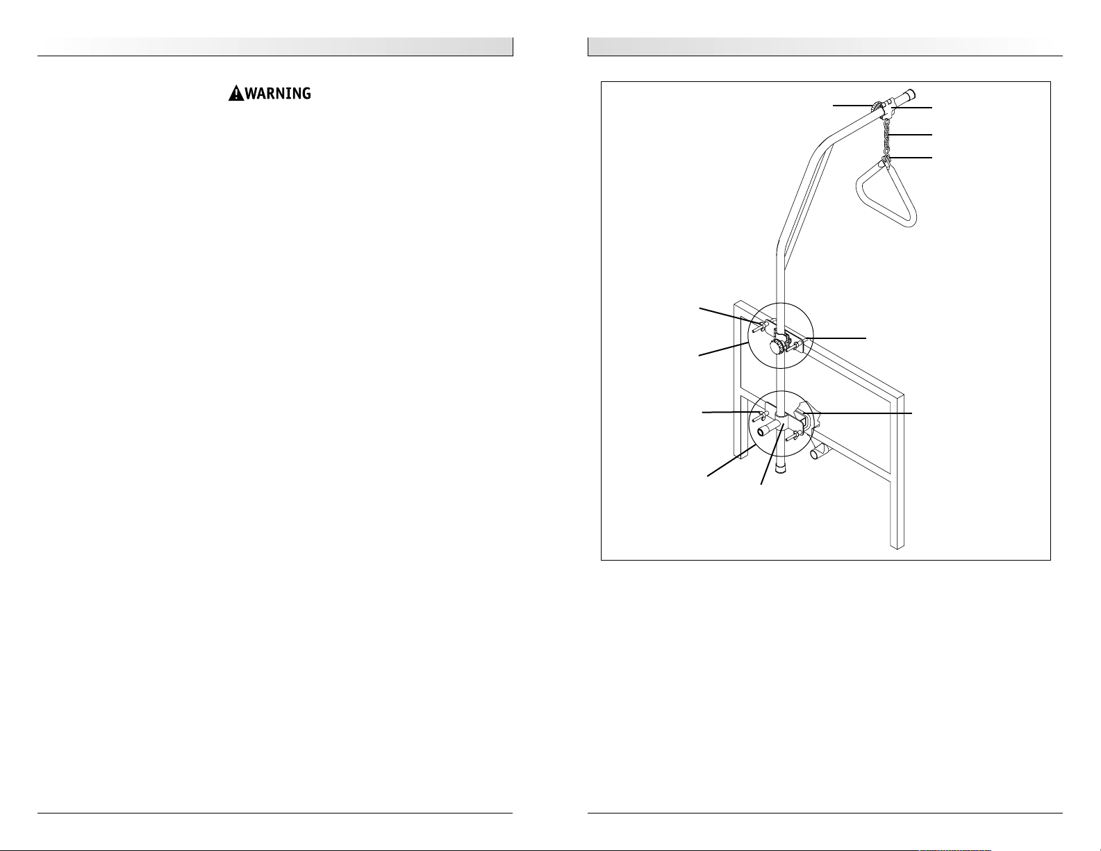
ATTACHING TRAPEZE TO BED END (Figure 1)
1. Locate the lower bed bracket and attach to the underneath of the bed head-
board. The tubular hook on the bracket should face up.
2. Tighten the wing nuts to secure the bracket in place.
3. Place the Trapeze on a flat surface for easy installation of the upper bed bracket.
4. Loosen the wing nuts on the upper bed bracket and slide the bracket 3/4 of the
way up the Trapeze bar. Once in position, tighten the wing nuts to secure.
5. Place the Trapeze bar assembly into the socket of the lower bracket now secured
on the bottom of the bed headboard.
6. Position the upper bracket so its tubular hook rests on the top of the bed head-
board. Tighten the wing nuts to secure the bracket in place.
Wing nut
Upper bed
bracket
Tubular hook
Socket
Tubular hook
Key
Clamp
“S” hook
Links
Figure 1
Wing nut
Lower bed
bracket
English
Franç ais
54
AVERTISSEMENT
• La potence fixe NE doit être utilisée QUE sur des lits munis de panneaux
à armature métallique.
• La potence de tête utilisée sur un lit peut soutenir une personne pesant
jusqu’à 114 kg (250 lbs.)
• La potence fixe est conçue pour servir d’appui, faciliter la stabilité de
l’utilisateur et l’aider à se repositionner dans le lit. La potence fixe n’est
PAS conçue pour soutenir le poids total d’une personne.
• Ne PAS installer ou régler la potence lorsqu’une personne se trouve dans
le lit.
• Ne PAS attacher la potence pivotante au support sur pied. Cela peut
faire basculer le support, et causer des blessures à l’utilisateur et/ou à
la personne qui prête son assistance.
• Avant de baisser le lit, assurez-vous que la potence est réglée à la hau-
teur maximale.
• Assurez-vous que les boutons de blocage font saillie sur les trous de
réglage du support sur pied Cela garantit que le support sur pied est
installé correctement et solidement ancré.
• Après l’installation et avant toute utilisation, veillez à ce que tous les
dispositifs de fixation soient serrés solidement.
• La potence ne doit pas servir de point de montage pour assurer la trac-
tion de matériel électrique ou non-éléctrique.
FIXATION DE LA POTENCE AU PANNEAU DE LIT (FIGURE 1)
1. Repérez le support inférieur du lit et attachez-le sous le panneau de tête du lit.
Le crochet tubulaire sur le support doit être tourné vers le haut.
2. Serrez les écrous à oreilles pour fixer solidement le support.
3. Placez la potence sur une surface plane pour faciliter l’installation du support
supérieur.
4. Desserrez les écrous à oreilles du support supérieur et glissez-le aux 3/4de la
hauteur de la barre de la potence. Lorsque le support est en place, serrez solide-
ment les écrous à oreilles.
5. Mettez la barre de la potence dans le manchon de raccord du support inférieur
qui a été fixé solidement sous le panneau de tête du lit.
6. Positionnez le support supérieur de manière que le crochet tubulaire repose sur
le panneau de tête du lit. Serrez les écrous à oreilles pour fixer solidement le
support.
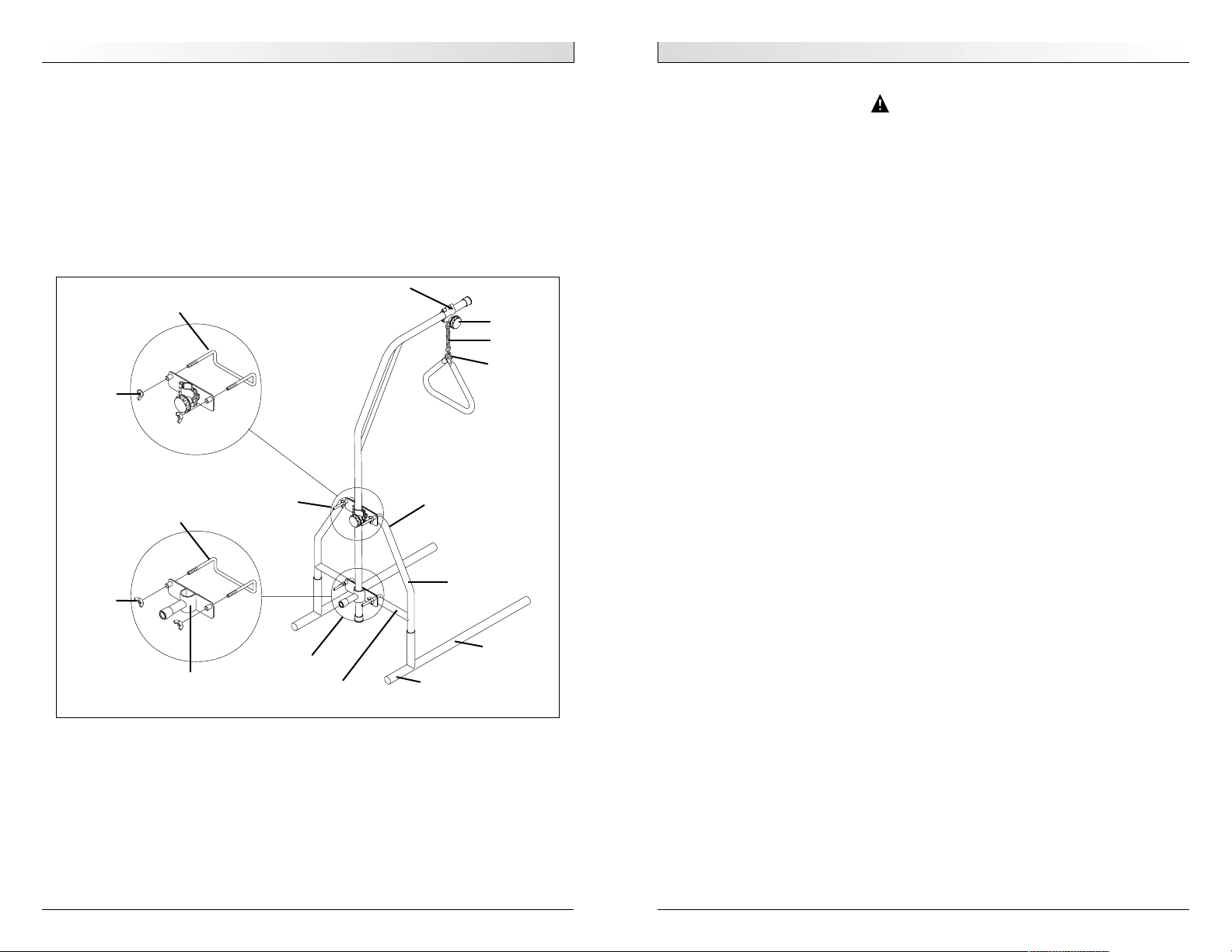
ATTACHING TRAPEZE TO FLOOR STAND (Figure 2)
1. Locate the Trapeze lower bed bracket and attach to the lower rail of the floor
stand. The tubular hook on the bracket should face down.
2. Tighten the wing nuts to secure the bracket in place.
3. Loosen the wing nuts on the upper bed bracket and slide the bracket 3/4 of the
way up the Trapeze bar. Once in position, tighten the wing nuts to secure.
4. Place the Trapeze bar assembly into the socket of the lower bracket now secured
on the lower floor stand rail.
5. Position the upper bracket, tubular hook facing down, on the top rail of the
floor stand. Tighten the wing nuts to secure the bracket in place.
ADJUST THE HEIGHT/POSITION OF THE TRAPEZE
Height:
Place any of the grab-bar chain links onto the “S” hook.
Position:
1. Loosen grab-bar key by turning counter-clockwise.
2. Slide the grab-bar clamp to desired position on the Trapeze bar.
3. Turn the grab-bar key clockwise to secure in place.
Figure 2
Tubular hook
Wing nut
Upper bed
bracket
Tubular hook
Wing nut
Socket
Lower bed
bracket
Short length
Lower Rail
Leg assembly
“A” frame
Upper rail
“S” hook
Links
Key
Clamp
 Loading...