


|
|
|
|
|
|
|
|
|
|
|
|
|
|
|
|
|
|
|
|
|
|
|
|
|
|
|
|
|
|
|
|
|
|
|
|
|
|
|
|
|
|
|
|
|
|
|
|
|
|
|
|
|
|
|
|
|
|
|
|
|
|
|
|
|
|
|
|
|
|
|
|
|
|
|
|
|
|
|
|
|
|
|
|
|
|
|
|
|
|
|
|
|
|
|
|
|
|
|
|
|
|
|
|
|
|
|
|
|
|
|
|
|
|
|
|
|
|
|
|
|
|
|
|
|
|
|
|
|
|
|
|
|
|
|
|
|
|
|
|
|
|
|
|
|
|
|
|
|
|
|
|
|
|
|
|
|
|
|
|
|
|
|
|
|
|
|
|
|
|
|
|
|
|
|
|
|
|
|
|
|
|
|
|
|
|
|
|
|
|
|
|
|
|
|
|
|
|
|
|
|
|
|
|
|
|
|
|
|
|
|
|
|
|
|
|
|
|
|
|
|
|
|
|
|
|
|
|
|
|
|
|
|
|
|
|
|
|
|
|
|
|
|
|
|
|
|
|
|
|
|
|
|
|
|
|
|
|
|
|
|
|
|
|
|
|
|
|
|
|
|
|
|
|
|
|
|
|
|
|
|
|
|
|
|
|
|
|
|
|
|
|
|
|
|
|
|
|
|
|
|
DeVilbiss® 5-Liter Series Oxygen |
|
|
|
|
|
||||||||||||||||||
|
For Product Numbers: |
|
||||||||||||||||||||||
|
Concentrator Service Manual |
|
|
Para productos Número: |
|
|
||||||||||||||||||
|
|
|
515ADS |
|
|
|||||||||||||||||||
|
DeVilbiss® Concentrador de Oxígeno |
|
|
515ADZ |
|
|
||||||||||||||||||
|
|
|
515AKS |
|
|
|||||||||||||||||||
|
Serie de 5 Litros Manual de Servicio |
|
|
515AKZ |
|
|
||||||||||||||||||
|
|
|
|
|
|
|||||||||||||||||||
|
|
|
|
|
|
|
|
|
|
|
|
|
|
|
|
|
|
|
|
|
|
|
|
|
|
|
|
|
|
|
|
|
|
|
|
|
|
|
|
|
|
|
|
|
|
|
|
|
|
|
|
|
|
|
|
|
|
|
|
|
|
|
|
|
|
|
|
|
|
|
|
|
|
|

 DANGER – NO
SMOKING

 PELIGRO – NO
FUMAR
CAUTION-Federal (U.S.A.) law restricts this device to sale by or on the order of a physician.
PRECAUCIÓN – Las leyes Federales (EE.UU.) restringen la venta de este equipo por o por orden de un médico

T A B L E O F C O N T E N T S
ESPAÑOL . . . . . . . . . . . . . . . . . . . . . . . . . . . . . . . . . . . . . . . . . . . . . . . . . . . . . . . . . . . . . . . . . . . . . . . . . . . . . . . . . . . . . . . . . . . . . . . . . . |
50 |
GENERAL INFORMATION |
|
Introduction . . . . . . . . . . . . . . . . . . . . . . . . . . . . . . . . . . . . . . . . . . . . . . . . . . . . . . . . . . . . . . . . . . . . . . . . . . . . . . . . . . . . . . . . . . . . . . . |
.3 |
Important Safeguards . . . . . . . . . . . . . . . . . . . . . . . . . . . . . . . . . . . . . . . . . . . . . . . . . . . . . . . . . . . . . . . . . . . . . . . . . . . . . . . . . . . . . . . . |
.4 |
Safety Precautions and General Warnings . . . . . . . . . . . . . . . . . . . . . . . . . . . . . . . . . . . . . . . . . . . . . . . . . . . . . . . . . . . . . . . . . . . . . . . |
.4 |
UNPACKING AND SETUP |
|
Initial Inspection . . . . . . . . . . . . . . . . . . . . . . . . . . . . . . . . . . . . . . . . . . . . . . . . . . . . . . . . . . . . . . . . . . . . . . . . . . . . . . . . . . . . . . . . . . . . |
.5 |
Patient Setup . . . . . . . . . . . . . . . . . . . . . . . . . . . . . . . . . . . . . . . . . . . . . . . . . . . . . . . . . . . . . . . . . . . . . . . . . . . . . . . . . . . . . . . . . . . . . . |
.5 |
Operating Instructions . . . . . . . . . . . . . . . . . . . . . . . . . . . . . . . . . . . . . . . . . . . . . . . . . . . . . . . . . . . . . . . . . . . . . . . . . . . . . . . . . . . . . . |
.6 |
MAINTENANCE |
|
Patient Alert System . . . . . . . . . . . . . . . . . . . . . . . . . . . . . . . . . . . . . . . . . . . . . . . . . . . . . . . . . . . . . . . . . . . . . . . . . . . . . . . . . . . . . . . . |
.7 |
Routine Patient Maintenance . . . . . . . . . . . . . . . . . . . . . . . . . . . . . . . . . . . . . . . . . . . . . . . . . . . . . . . . . . . . . . . . . . . . . . . . . . . . . . . . . |
.7 |
Periodic Homecare Provider Preventative Maintenance . . . . . . . . . . . . . . . . . . . . . . . . . . . . . . . . . . . . . . . . . . . . . . . . . . . . . . . . . . . . |
.8 |
Between Patient Maintenance . . . . . . . . . . . . . . . . . . . . . . . . . . . . . . . . . . . . . . . . . . . . . . . . . . . . . . . . . . . . . . . . . . . . . . . . . . . . . . . . . |
.8 |
Preventative Maintenance Summary . . . . . . . . . . . . . . . . . . . . . . . . . . . . . . . . . . . . . . . . . . . . . . . . . . . . . . . . . . . . . . . . . . . . . . . . . . . . |
.8 |
TROUBLESHOOTING
System Operation . . . . . . . . . . . . . . . . . . . . . . . . . . . . . . . . . . . . . . . . . . . . . . . . . . . . . . . . . . . . . . . . . . . . . . . . . . . . . . . . . . . . . . . . . . .9
Normal Operating Sequence . . . . . . . . . . . . . . . . . . . . . . . . . . . . . . . . . . . . . . . . . . . . . . . . . . . . . . . . . . . . . . . . . . . . . . . . . . . . . . . . . .9
Simplified Troubleshooting . . . . . . . . . . . . . . . . . . . . . . . . . . . . . . . . . . . . . . . . . . . . . . . . . . . . . . . . . . . . . . . . . . . . . . . . . . . . . . . . . . . .10
Troubleshooting Chart A . . . . . . . . . . . . . . . . . . . . . . . . . . . . . . . . . . . . . . . . . . . . . . . . . . . . . . . . . . . . . . . . . . . . . . . . . . . . . . . . . . . . .11
Troubleshooting Chart B . . . . . . . . . . . . . . . . . . . . . . . . . . . . . . . . . . . . . . . . . . . . . . . . . . . . . . . . . . . . . . . . . . . . . . . . . . . . . . . . . . . . .12
Troubleshooting Chart C . . . . . . . . . . . . . . . . . . . . . . . . . . . . . . . . . . . . . . . . . . . . . . . . . . . . . . . . . . . . . . . . . . . . . . . . . . . . . . . . . . . .12
Troubleshooting Chart D . . . . . . . . . . . . . . . . . . . . . . . . . . . . . . . . . . . . . . . . . . . . . . . . . . . . . . . . . . . . . . . . . . . . . . . . . . . . . . . . . . . .12
Troubleshooting Chart E . . . . . . . . . . . . . . . . . . . . . . . . . . . . . . . . . . . . . . . . . . . . . . . . . . . . . . . . . . . . . . . . . . . . . . . . . . . . . . . . . . . . .12
Troubleshooting Chart F . . . . . . . . . . . . . . . . . . . . . . . . . . . . . . . . . . . . . . . . . . . . . . . . . . . . . . . . . . . . . . . . . . . . . . . . . . . . . . . . . . . . .13
COMPONENT TESTING, REPAIR, AND REPLACEMENT |
|
Proper Repair Procedures . . . . . . . . . . . . . . . . . . . . . . . . . . . . . . . . . . . . . . . . . . . . . . . . . . . . . . . . . . . . . . . . . . . . . . . . . . . . . . . . . |
. . .14 |
Cabinet Removal . . . . . . . . . . . . . . . . . . . . . . . . . . . . . . . . . . . . . . . . . . . . . . . . . . . . . . . . . . . . . . . . . . . . . . . . . . . . . . . . . . . . . . . . |
. . .14 |
Accumulator Pressure Test . . . . . . . . . . . . . . . . . . . . . . . . . . . . . . . . . . . . . . . . . . . . . . . . . . . . . . . . . . . . . . . . . . . . . . . . . . . . . . . . |
. . .15 |
Capacitor . . . . . . . . . . . . . . . . . . . . . . . . . . . . . . . . . . . . . . . . . . . . . . . . . . . . . . . . . . . . . . . . . . . . . . . . . . . . . . . . . . . . . . . . . . . . . . |
. . .15 |
Compressor . . . . . . . . . . . . . . . . . . . . . . . . . . . . . . . . . . . . . . . . . . . . . . . . . . . . . . . . . . . . . . . . . . . . . . . . . . . . . . . . . . . . . . . . . . . . |
. . .15 |
Cooling Fan . . . . . . . . . . . . . . . . . . . . . . . . . . . . . . . . . . . . . . . . . . . . . . . . . . . . . . . . . . . . . . . . . . . . . . . . . . . . . . . . . . . . . . . . . . . . |
. . .17 |
Final Check Valve . . . . . . . . . . . . . . . . . . . . . . . . . . . . . . . . . . . . . . . . . . . . . . . . . . . . . . . . . . . . . . . . . . . . . . . . . . . . . . . . . . . . . . . . |
. . .17 |
Flow Meter . . . . . . . . . . . . . . . . . . . . . . . . . . . . . . . . . . . . . . . . . . . . . . . . . . . . . . . . . . . . . . . . . . . . . . . . . . . . . . . . . . . . . . . . . . . . |
. . .17 |
Hour Meter . . . . . . . . . . . . . . . . . . . . . . . . . . . . . . . . . . . . . . . . . . . . . . . . . . . . . . . . . . . . . . . . . . . . . . . . . . . . . . . . . . . . . . . . . . . . |
. . .18 |
Molecular Sieve Beds . . . . . . . . . . . . . . . . . . . . . . . . . . . . . . . . . . . . . . . . . . . . . . . . . . . . . . . . . . . . . . . . . . . . . . . . . . . . . . . . . . . . . |
. . .18 |
Power Cord . . . . . . . . . . . . . . . . . . . . . . . . . . . . . . . . . . . . . . . . . . . . . . . . . . . . . . . . . . . . . . . . . . . . . . . . . . . . . . . . . . . . . . . . . . . . |
. . .18 |
Power Switch . . . . . . . . . . . . . . . . . . . . . . . . . . . . . . . . . . . . . . . . . . . . . . . . . . . . . . . . . . . . . . . . . . . . . . . . . . . . . . . . . . . . . . . . . . . |
. . .18 |
Pressure Regulator . . . . . . . . . . . . . . . . . . . . . . . . . . . . . . . . . . . . . . . . . . . . . . . . . . . . . . . . . . . . . . . . . . . . . . . . . . . . . . . . . . . . . . |
. . .18 |
Printed Circuit Board (PC board) . . . . . . . . . . . . . . . . . . . . . . . . . . . . . . . . . . . . . . . . . . . . . . . . . . . . . . . . . . . . . . . . . . . . . . . . . . . |
. . .19 |
Rotary Valve . . . . . . . . . . . . . . . . . . . . . . . . . . . . . . . . . . . . . . . . . . . . . . . . . . . . . . . . . . . . . . . . . . . . . . . . . . . . . . . . . . . . . . . . . . . . |
. . .19 |
Sieve Bed Check Valves . . . . . . . . . . . . . . . . . . . . . . . . . . . . . . . . . . . . . . . . . . . . . . . . . . . . . . . . . . . . . . . . . . . . . . . . . . . . . . . . . . . |
. . .20 |
FIGURES, DIAGRAMS,AND VIEWS |
|
Figure Index . . . . . . . . . . . . . . . . . . . . . . . . . . . . . . . . . . . . . . . . . . . . . . . . . . . . . . . . . . . . . . . . . . . . . . . . . . . . . . . . . . . . . . . . . . . . |
. . .21 |
Exterior Views . . . . . . . . . . . . . . . . . . . . . . . . . . . . . . . . . . . . . . . . . . . . . . . . . . . . . . . . . . . . . . . . . . . . . . . . . . . . . . . . . . . . . . . . . . |
22-24 |
Interior Views . . . . . . . . . . . . . . . . . . . . . . . . . . . . . . . . . . . . . . . . . . . . . . . . . . . . . . . . . . . . . . . . . . . . . . . . . . . . . . . . . . . . . . . . . . . |
25-37 |
Other Figures . . . . . . . . . . . . . . . . . . . . . . . . . . . . . . . . . . . . . . . . . . . . . . . . . . . . . . . . . . . . . . . . . . . . . . . . . . . . . . . . . . . . . . . . . . . |
38-42 |
Pneumatic and Wiring Diagrams . . . . . . . . . . . . . . . . . . . . . . . . . . . . . . . . . . . . . . . . . . . . . . . . . . . . . . . . . . . . . . . . . . . . . . . . . . . . |
43-44 |
WARRANTY INFORMATION . . . . . . . . . . . . . . . . . . . . . . . . . . . . . . . . . . . . . . . . . . . . . . . . . . . . . . . . . . . . . . . . . . . . . . . . . . . . |
. . .45 |
ORDERING INFORMATION AND PARTS LIST |
|
Ordering Information . . . . . . . . . . . . . . . . . . . . . . . . . . . . . . . . . . . . . . . . . . . . . . . . . . . . . . . . . . . . . . . . . . . . . . . . . . . . . . . . . . . . |
. . .46 |
Parts Return and Ordering Policy . . . . . . . . . . . . . . . . . . . . . . . . . . . . . . . . . . . . . . . . . . . . . . . . . . . . . . . . . . . . . . . . . . . . . . . . . . . |
. . .46 |
Parts List . . . . . . . . . . . . . . . . . . . . . . . . . . . . . . . . . . . . . . . . . . . . . . . . . . . . . . . . . . . . . . . . . . . . . . . . . . . . . . . . . . . . . . . . . . . . . . . |
47-48 |
SPECIFICATIONS . . . . . . . . . . . . . . . . . . . . . . . . . . . . . . . . . . . . . . . . . . . . . . . . . . . . . . . . . . . . . . . . . . . . . . . . . . . . . . . . . . . . . . . |
. . .49 |
LT-1928 |
2 |

G E N E R A L I N F O R M A T I O N
INTRODUCTION
This service manual was designed to provide Sunrise Medical Respiratory Products Division qualified service technicians and homecare providers with the proper maintenance, service, safety, and repair procedures for the DeVilbiss Oxygen Concentrator.
Read and understand all the information contained in this service manual before attempting to operate or perform any maintenance on the concentrator.
An oxygen concentrator is a device that delivers highly concentrated oxygen for therapeutic applications.
Room air is a mixture of 78% nitrogen, 21% oxygen, 1% argon and other gases.The concentrator draws in room air, separates the nitrogen from the oxygen, and delivers concentrated oxygen to the patient through an oxygen port.
For more in-depth classroom type training, Sunrise Medical holds oxygen concentrator service schools. For service school information, contact the Respiratory Technical Service Department at 1-800-333-4000 (814-443-4881).
NOTE: Sunrise Medical reserves the right to alter or change the design of the DeVilbiss Oxygen Concentrator series. Hence, slight differences in construction or components may exist between the unit in hand and what is described in this manual.
3 |
LT-1928 |

G E N E R A L I N F O R M A T I O N
IMPORTANT SAFEGUARDS
Read all instructions before operating the oxygen concentrator. Important information is highlighted by these terms:
WARNING: Safety information for hazards that might cause serious injury or death.
CAUTION: Information for preventing damage to the product.
NOTE: Information to which you should pay special attention.
SAFETY PRECAUTIONS AND GENERAL WARNINGS
A.Federal (U.S.A.) law restricts this device to sale by or on the order of a physician.
B. WARNING: Oxygen promotes rapid burning. Do not smoke when using this unit or when near a
person receiving oxygen therapy. Do not operate the oxygen concentrator within a minimum of five feet (1.6m) from hot, sparking, or burning objects or naked flames. Do not use in rooms heated by paraffin or portable gas heaters.
C.Do not place a humidifier with an oxygen patient unless prescribed by a physician and then only a bubble-type humidifier should be used.
D.Do not connect the oxygen concentrator to an electrical outlet controlled by a wall switch; the outlet should be independent of other appliances.
E.Do not use an electrical adapter or extension cord with the oxygen concentrator.
F.Only operate the oxygen concentrator with all filters in place; do not operate if the air filter is wet.
G.WARNING: Electric shock hazard. Do not remove cabinet.The cabinet should only be removed by a qualified Sunrise Medical homecare provider.
H.WARNING: Disconnect the power cord from the wall outlet before attempting repairs on the unit. Extra care should be taken if it is necessary to operate the unit with the cabinet removed.
I.WARNING: Do not use oils, greases, or any petrole- um-based solvents/cleaners on or near the unit. Use only materials that are compatible with oxygen.
J.WARNING: Electric Shock Hazard.When replacing the capacitor, do not touch the terminals or allow metal objects to come in contact with the terminals on the capacitor. The capacitor may hold a charge for several days after the unit is turned off.The capacitor is located in the base of the unit next to the cooling fan.
K.Use only Sunrise Medical concentrator replacement parts and accessories.
L.Do not use regenerated sieve material.
LT-1928 |
4 |

U N P A C K I N G A N D S E T U P
INITIAL INSPECTION
It is suggested that an initial inspection be performed upon receiving the oxygen concentrator.
1.After removing the DeVilbiss Oxygen Concentrator from the carton, examine it for any external damage. If shipping damage has occurred, contact the Sunrise Medical Customer Service Department at 1-800-333-4000 (814-443-4881) for specific instructions. Save the carton for possible later return; note the position of the unit and placement of the packing material.
2.Open the filter door (Figure 3) and record the number of hours on the hour meter. Check to make sure the air filter is in place.
3.Check to be sure the intake bacteria filter (Figure 4) is in place.
4.Plug the unit into an electrical outlet, turn the unit “On,” and check the audible and visible alarms.
5.Set the flow meter to maximum recommended liter flow and let the unit run for at least 20 minutes.
6.Use an oxygen analyzer to check the concentration.
NOTE: If the unit fails to operate properly (oxygen concentration not within specification) or if internal damage is found, contact the Sunrise Medical Customer Service Department at 1-800-333-4000 (814-443-4881).
PATIENT SETUP
1.Position the unit near an electrical outlet in the room where the patient spends most of his or her time.
NOTE: Do not connect to an electrical outlet controlled by a wall switch.The outlet should be independent of other appliances.
2.Position the unit at least 6 inches (16 cm) from walls, draperies, or any other objects that might prevent the proper flow of air in and out of the oxygen concentrator.
3.Locate the unit a minimum of 5 feet (1.6 meters) from fireplaces, radiators, heaters, and hot-air registers.
 WARNING: Oxygen promotes rapid burning. Do not smoke when using this unit or when near a
person receiving oxygen therapy. Do not operate the oxygen concentrator within a minimum of 5 feet (1.6 meters) from hot, sparking, or burning objects or naked flames. Do not use in rooms heated by paraffin or portable gas heaters.
WARNING: Electric Shock Hazard. Only qualified Sunrise Medical homecare providers may remove the cabinet.
4.Attach the appropriate oxygen accessories (oxygen tubing or humidifier) to the oxygen outlet port.
NOTE: A maximum of 50 feet (15 meters) of tubing plus 7 feet (2.1 meters) of cannula plus a bubble humidifier is allowed between the concentrator and the patient.
Oxygen Tubing Only Connection (Figure 1)
1.Thread the cannula fitting (part #CN100) onto the oxygen outlet port.
2.Attach the 5/32” (4 mm) I.D. oxygen tubing (part #OST07, OST15, OST25, or OST50).
Oxygen Tubing with Humidification Connection
If the physician has prescribed an oxygen humidifier as part of the patient’s therapy, follow these steps:
1.Fill the humidifier bottle (part #HUM16) with distilled water. Do not overfill. (If using a prefill, go to Step 3.)
2.Thread the wing nut located on the top of the humidifier bottle to the oxygen outlet port so that it is suspended. Make sure it is securely tightened.
3.Attach the 5/32" (4 mm) I.D. oxygen tubing (part # OST07, OST15, OST25, or OST50), not to exceed 50 feet (15 meters), directly to the humidifier bottle outlet fitting.
NOTE: For optimum performance, the DeVilbiss Oxygen Concentrator has a preset nominal output pressure of 8.5 psi (58.6 kPa). Use only “bubble-type” humidifiers. Do not use “jet-type” humidifiers.
NOTE: Condensation from the humidifier may occur in longer lengths of tubing or if the tubing is laying on a cold floor.This can be reduced by using a removable humidifier stand (part #MC44DM-509).
To use the stand:
1.Attach a straight humidifier adapter fitting (part #444-506) to the bottle by turning the wing nut on the humidifier until it is tight on the fitting.
2.Secure the bottle in the strap.
3.Attach one end of the oxygen tubing to the oxygen outlet on the unit and the other end to the plastic adapter fitting on the humidifier. Locate the humidifier near the patient.
When ready for operation
1.Attach the nasal cannula (part #CAN00), catheter, or face mask to the oxygen tubing (per the manufacturer’s directions).
2.Follow the Operating Instructions on the next page.
5 |
LT-1928 |

U N P A C K I N G A N D S E T U P
OPERATING INSTRUCTIONS
1.Remove the power cord completely from the strap. Make sure the power switch is in the “Off” position.
2.115 Volt Units– Insert the plug into an electrical outlet.The DeVilbiss Oxygen Concentrator uses a two-prong polarized plug and is double-insulated to protect against electric shock.
WARNING:The plug on the DeVilbiss 515ADZ and 515ADS concentrators has one blade wider than the other.To reduce the risk of electric shock, this plug is intended to fit in a wall outlet only one way. Do not attempt to defeat this safety feature.
WARNING: Improper use of the power cord and plugs can cause a burn, fire, or other electric shock hazards. Do not use the unit if the power cord is damaged.
 WARNING: Oxygen promotes rapid burning. Do not smoke when using this unit or when near a per-
son receiving oxygen therapy. Do not operate the oxygen concentrator within a minimum of five feet (1.6m) from hot, sparking, or burning objects or naked flames. Do not use in rooms heated by paraffin or portable gas heaters.
3.Press the power switch to the “On” position.When the unit is turned on, the “Service Required” light will illuminate and an audible signal will sound (the patient alert system) momentarily. The “Power” light also illuminates.
Only DeVilbiss Oxygen Concentrators with OSD®
The OSD is an optional device within DeVilbiss concentrators that monitors the oxygen produced by the unit.The OSD operates as follows:
•Normal Oxygen (green light) - oxygen purity normal
•Low Oxygen (yellow light) - oxygen purity low–requires servicing
NOTE: If the oxygen purity continues to fall, an audible signal will sound intermittently. If the oxygen purity continues to fall to a low enough level, the yellow “Low Oxygen” light will turn off and the red “Service Required” light will turn on.
NOTE: Refer to Specifications for specific alarm settings.
When the unit with the OSD is turned “On,” all four indicator lights (Power, Service Required, Low Oxygen, and Normal Oxygen) on the front panel will briefly illuminate. After a few seconds, only the “Power” and “Normal Oxygen” lights will remain on.
NOTE: After Power On, the OSD conducts a continuous diagnostic evaluation to check for a fault in the piezo electronics. If this condition is detected by the OSD electronics at any time during concentrator operation, the green “Normal Oxygen” OSD light will turn off and the beeping audible and blinking red “Service Required” light alarms activate.
Otherwise for the first fifteen minutes of operation, the green “Normal Oxygen” light will remain illuminated during the oxygen stabilization process.After that time, the OSD will begin monitoring the oxygen purity every second.
4.Slowly turn the flow meter knob until the flow meter ball is centered on the line next to the appropriate flow rate.
NOTE: When the flow meter knob is turned clockwise, the flow decreases (and eventually will shut off the oxygen flow). When the knob is turned counter-clockwise, the flow increases.
NOTE: Use low output flow meter (part #515LF-607) for flow rates under 1 lpm.
NOTE: The unit may require up to 20 minutes for the oxygen concentration and flow rate to stabilize.The flow rate should be monitored and readjusted if necessary.
5.The flow meter has a locking device. If it is necessary to preset and lock in the prescribed flow rate, tighten the set screw located on the hex nut just below the control knob using a 1/16" Allen bit. No adjustment can be made without loosening the set screw.
6.The DeVilbiss oxygen concentrator is now ready for use.
LT-1928 |
6 |

M A I N T E N A N C E
PATIENT ALERT SYSTEM
The DeVilbiss Oxygen Concentrator patient alert system will detect unit component failure.This system is comprised of both visible and audible alarms which signal the patient if a malfunction should occur.
The visible alarm located on the front panel (Figure 1) reads “Service Required.” The audible alarm system is internally powered; no batteries are required.When the indicator lights illuminate or the audible alarm sounds, other than during unit start-up, a problem has occurred.
Non-OSD models:
•Power Failure (Blinking red “Service Required” light and pulsing audible alarm)
•Low Flow (Continuous red “Service Required” light and
audible alarm)
OSD models:
•Power Failure (Blinking red “Service Required” light and pulsing audible alarm)
•Low Flow (Below 0.5 lpm) (Continuous red “Service Required” light and audible alarm)
•Below Normal Oxygen (84% to 75%, yellow “Low Oxygen” light. 75% to 60%, yellow “Low Oxygen” light and beeping audible alarm. Less than 60%, red “Service Required” light and beeping audible alarm.) Refer to Specifications for spe-
cific alarm settings.
The visible and audible alarms will activate for approximately 15 minutes in a no power situation. If the unit is turned “On” without power or power is removed later, no alarm will sound for the first 10 seconds.After that time, the alarm will produce an audible pulse every few seconds while the visible alarm blinks. Power for this alarm is provided by a capacitor on the PC board.
NOTE: If the concentrator has been unused for an extended period, the unit must run several minutes before the power fail alarm will activate.
The PC (printed circuit) board (Figure 5) is responsible for controlling the system and alarms.
NOTE: A high pressure condition is indicated by the audible (a “popping” sound) release of pressure from a pressure relief valve located on the compressor head.
ROUTINE PATIENT MAINTENANCE
The oxygen patient should perform the following maintenance:
Oxygen Humidifier (reusable bottles only)
The patient should clean the humidifier bottle daily.The patient should follow the instructions supplied by the manufacturer. If no cleaning instructions were supplied, these steps should be followed:
•Wash the humidifier bottle in a solution of hot water and dishwashing detergent.
•Soak the humidifier in a solution of one part white vinegar to three parts hot water for 30-45 minutes.This solution acts as a germicidal agent.
•Rinse thoroughly with hot tap water and refill with distilled water for use. Do not overfill.
Cannula/Mask and Tubing
The patient should clean and replace the cannula or mask and tubing as instructed by the manufacturer.
Air Filter and Oxygen Outlet Connector
The air filter (Figure 3) and oxygen outlet connector should be cleaned at least once a week by the patient.To clean, these steps should be followed:
1.Remove the air filter located in the door on the back of the unit. Remove the oxygen outlet connector (if used) from oxygen outlet port (Figure 1).
2.Wash in a solution of warm water and dishwashing detergent.
3.Rinse thoroughly with warm tap water and towel dry.The filter should be completely dry before reinstalling.
WARNING: Do not attempt to operate the unit without the air filter or while the filter is still damp.
NOTE: The air filter should be monitored more closely in environments with abnormal amounts of dust and lint.
CAUTION: Operation of the DeVilbiss Oxygen Concentrator in extreme environments or without the air filter will prematurely occlude the intake bacteria filter and cause a decrease in the unit performance.
Exterior Cabinet
The patient should clean the concentrator exterior cabinet by using a damp cloth or sponge with a mild household cleaner and wiping it dry.
WARNING: Do not apply liquids directly to the cabinet or utilize any petroleum-based solvents or cleaning agents.
7 |
LT-1928 |

M A I N T E N A N C E
PERIODIC HOMECARE PROVIDER
PREVENTATIVE MAINTENANCE
Every DeVilbiss Oxygen Concentrator is tested at the factory. To assure continued trouble-free performance, the following preventative maintenance should be performed by the homecare provider during periodic oxygen patient visits. Failure to properly maintain the unit will void the warranty.
1.Check the oxygen concentration with an oxygen analyzer (part #O2ANA)—every 3 months on non-OSD units or every two years on OSD units.
a.Calibrate the oxygen analyzer prior to checking the oxygen concentration.The analyzer should be properly calibrated using the manufacturer’s recommended procedure.
NOTE: Changes in temperature, altitude, or humidity may affect the analyzer’s oxygen concentration reading.The analyzer should be calibrated in similar conditions to the location of the concentrator.
b.The concentrator must operate for a minimum of 20 minutes before checking the oxygen concentration.
c.Connect the analyzer to the unit’s oxygen outlet port (Figure 1) and wait until the display stabilizes.
d.Record the reading.
2.Check the audible alarm and indicator lights every two years. When the power switch is turned “On,” listen for the audible alarm and check to see if the front panel indicator lights are operating.
3.Change intake filter as follows:
a.Extended life intake bacteria filter (part # 515DZ-605) - Inspect once a year. Change as necessary, not to exceed 8760 hours.
b.Open the filter door and replace filter as required.
4.Change the final bacteria filter (part #PV5LD-651) every two years or 17,520 hours.
a.Unplug the unit, remove the cabinet, and loosen the bib.
b.Remove the hose from each end of the filter (Figure 8) and discard the filter.
c.Install the new final bacteria filter with the “IN” fitting toward the flow meter.
d.Tighten the bib and replace the cabinet.
5.Check the system performance every two years of operation by measuring the accumulator pressure swing. Use the
Accumulator Pressure Test described in the chapter Component Testing, Repair and Replacement.
NOTE: This PM Schedule reflects:
•5000 hour usage equal to one year
•a normal, clean operating environment. The homecare provider is responsible for:
•determining the condition of the concentrator operating environment.
•determining a preventative maintenance interval frequency (not to exceed the schedule stated above which takes into consideration the specific operating environment).
BETWEEN PATIENT MAINTENANCE
1.Discard oxygen tubing, cannula & humidifier bottle.
2.Wash or replace the cabinet air filter.
3.Wash the concentrator cabinet.
4.Check oxygen concentration. If the unit falls within specification, the extended life intake bacteria filter does not need to be replaced between patients.
PREVENTATIVE MAINTENANCE SUMMARY
Patient
Daily |
Clean the humidifier bottle (if used). |
Weekly |
Clean air filter on back of unit. |
|
Clean exterior of cabinet. |
Other |
Clean and replace cannula/mask and tubing as |
|
instructed by manufacturer. |
Homecare Provider
Change intake bacteria filter as necessary following requirements in step 3.
3 months Check oxygen concentration on non-OSD units. Check the concentrator environment, and set a maintenance interval of less than 3 months if required.
2 years Check audible alarm and indicator lights. Change final bacteria filter (change within 17,520 hours).
Check system performance.
Check oxygen concentration on OSD units.
LT-1928 |
8 |

T R O U B L E S H O O T I N G
SYSTEM OPERATION
The DeVilbiss Oxygen Concentrator uses a pressure swing adsorption system.The air is drawn into the unit through air filters and into a double-head compressor.
A pneumatic diagram of the system is shown in Figure 14.
The compressed air passes through a rotary valve (Figure 5), which is cycled at a pre-determined rate, and is directed into one of two sieve beds.The sieve beds contain molecular sieve material which is a synthetically-produced inorganic silicate. It is very porous and has the unique ability to selectively adsorb nitrogen from the air as it passes through the sieve bed.
As one bed is being pressurized, the other bed is quickly depressurized.This allows the nitrogen that was adsorbed during its pressurization cycle to be exhausted from the sieve material.
The nitrogen is released through exhaust ports located on the rotary valve assembly.The ports are connected to a single piece of hose running from the valve to the exhaust muffler.
Also during each bed pressurization, a small amount of oxygen flows through an orifice (Figure 9) from the pressurized bed into the depressurizing bed.The orifice is clamped inside a long piece of blue tubing connecting the outlets of the two sieve beds.This helps purge the nitrogen from the depressurizing bed.
The beds will continue to be alternately pressurized and depressurized as the unit operates.
Oxygen leaving the sieve beds is directed through a check valve to the accumulator tank.A pressure regulator (Figure 9) on the tank controls the oxygen pressure as it leaves the accumulator and enters the flow meter.The flow meter allows the oxygen flow to be controlled and adjusted to the level prescribed by the patient’s physician. From the flow meter the oxygen passes through the final bacteria filter (Figure 8), a check valve, and finally the oxygen outlet port to the patient.
The DeVilbiss Oxygen Concentrator operates on a timed cycle.The cycling is controlled by the PC board.The PC board will send voltage to the valve causing it to shift and alternately pressurize the sieve beds.
The PC board also activates the electronic alarm system.A high pressure condition will be indicated with a “popping” type sound produced by release of pressure from a pressure relief valve on the compressor head. Low flow and power failure are indicated by audible and visible alarms.
The 515 OSD Models operating system incorporates “turndown” technology.The PC board constantly monitors the flow rate and will decrease the cycle time whenever the flow rate is less than 2.5 LPM.Therefore it “turns-down” the cycle based on lower oxygen demand.As a result, the unit runs cooler with less power consumption.
NORMAL OPERATING SEQUENCE
When the concentrator is turned “On,” the following cycling sequence can be observed by attaching pressure gauges to the sieve bed test points.
1.The rotary valve is quickly cycled several times to relieve residual bed pressure preventing a static condition in the compressor.This rapid cycling only happens on start-up and is clearly heard as pressure is being quickly exhausted several times through the exhaust muffler that is connected to the valve.
2.The PC board applies a short DC voltage signal to the valve. The valve will stop for approximately 7 seconds causing the right bed to pressurize first while the left bed depressurizes to approximately 2 PSI (14 kPa).
3.Voltage is again applied to the valve for a short time.The valve will stop for approximately 0.7 seconds. During this time the sieve bed pressures are equalized.
4.A short DC voltage signal is again applied to the valve.The valve will stop for approximately 7 seconds causing the left bed to pressurize while the right bed depressurizes to approximately 2 PSI (14 kPa).
5.A short DC voltage signal is again applied to the valve.The valve will stop for approximately 0.7 seconds. During this time, the sieve bed pressures are equalized.
6.The cycle then repeats with step 2.
NOTE: In the “turn-down” mode (OSD models only), the fixed cycle time is decreased to approximately 3 seconds and the bed pressure equalization time to approximately 0.3 seconds.
NOTE: High-end sieve bed pressure should not exceed 1/2 PSI (4 kPa) above high-end accumulator pressures. Refer to Specifications for normal pressures obtained during the cycle.
9 |
LT-1928 |

T R O U B L E S H O O T I N G
SIMPLIFIED TROUBLESHOOTING
The key to simple troubleshooting is to recognize which type of problem exists and select the most effective approach to solving the problem.The different types of problems and the approaches for solutions are as follows:
Type I—The unit runs but a low pressure and flow or high pressure condition exists.
NOTE: Low pressure or flow are indicated by both a visible and audible alarm. High pressure is indicated by a “popping” sound caused by the pressure relief valve.
1.Connect test gauges to sieve bed tests points (Figure 7).
2.Refer to the Normal Operating Sequence to make sure the unit is cycling properly.
3.If bed pressure is rising slowly, check for occluded filters and severe leaks. If filters are clean and there are no leaks, then the compressor is defective.
4.If the pressure relief valve is releasing pressure, observe whether the unit is cycling or not.
5.If the unit is not cycling or has uneven bed pressures, this indicates that the rotary valve is not operating correctly. Refer to the Rotary Valve Testing described in the chapter Component Testing, Repair and Replacement.
6.If the unit is cycling in conjunction with very high bed pressures, this indicates defective sieve beds.
Type II—The compressor will not start when the unit is turned on.
1.Verify that the cooling fan is running; if it is not, determine where you are losing power.
2.Check for compressor voltage at the compressor connector.
3.If voltage is present, then the capacitor or compressor is defective.
4.If voltage is not present, the wire harness is defective.
WARNING: Mechanical Hazard. Keep fingers, loose clothing, etc. away when working on compressor.
Type III—The concentrator runs and continues to cycle but has low oxygen concentrations.
1.Connect test gauges and check for higher or lower than normal bed pressures.
a.High pressures indicate defective sieve beds.
b.Low pressures indicate occluded filters, leaks, or defective compressor.
c.Uneven bed pressures indicate valve is not operating correctly.
2.Check for oxygen leaks at:
• |
sieve beds |
• |
flow meter |
• |
accumulator tank |
• |
final bacteria filter |
• |
pressure regulator |
• |
final check valve |
•outlet port
NOTE: Check for leaks using a certified leak detection solution such as Snoop® or equivalent (must not contain ethylene glycol).Apply leak test solution to all fittings and hose connections with unit running. If an air leak is present, the solution will bubble.All leaks should be repaired before putting the unit back in service.
CAUTION: Do not apply leak test solution to any part of the rotary valve or the main PC Board assembly.
3. Test accumulator tank pressure. If pressure is lower than normal, then sieve bed check valves are defective.
NOTE: For normal system pressures refer to Specifications.
LT-1928 |
10 |
T R O U B L E S H O O T I N G
TROUBLESHOOTING CHART A
Visible Alarm |
Audible Alarm |
Compressor |
Power Light |
|
||
OFF |
OFF |
ON |
ON |
|
||
|
|
|
|
|
|
|
Other Symptoms |
|
Possible Cause |
|
|
Possible Remedy |
|
|
|
|
|
|||
|
|
|
|
|
|
|
Pulsating air noise |
|
Intake filter not in place or defective |
|
Check filter and replace if necessary |
|
|
|
|
Compressor intake hose disconnected |
|
Reconnect hose |
|
|
|
|
|
|
|
|
|
Excessive noise |
|
Loose or defective motor mounts |
|
|
Replace motor mounts |
|
|
|
Defective compressor |
|
|
Replace compressor |
|
|
|
|
|
|
|
|
|
|
Defective cooling fan |
|
|
Replace cooling fan |
|
|
|
|
|
|
|
|
Fluctuating oxygen flow |
|
Occluded humidifier |
|
|
Clean or replace humidifier |
|
|
|
Use of improper humidifier |
|
|
Use only a bubble-type humidifier |
|
|
|
Occluded filters |
|
|
Clean or replace filters |
|
|
|
Occluded or defective cannula and tubing |
|
Detach cannula from oxygen delivery tubing. If |
|
|
|
|
|
|
|
proper flow is not attained, check tubing for |
|
|
|
|
|
|
kinks or other obstructions. Clean or straighten |
|
|
|
|
|
|
as required or replace tubing if necessary. |
|
|
|
|
|
|
|
|
|
|
Use of excess oxygen tubing |
|
|
The unit is designed to deliver 5 lpm with a |
|
|
|
|
|
|
cannula on 50 feet (15 meters) of approximately |
|
|
|
|
|
|
5/32” (4 mm) inside diameter tubing. Smaller |
|
|
|
|
|
|
diameter tubing or the addition of any other |
|
|
|
|
|
|
flow restriction may prevent obtaining the |
|
|
|
|
|
|
desired flow rate. |
|
|
|
|
|
|
|
|
|
|
Defective flow meter |
|
|
Replace flow meter |
|
|
|
|
|
|
|
|
|
|
Leak in system |
|
|
Check for leaks in all hoses and fittings |
|
|
|
Defective compressor |
|
|
Replace compressor |
|
|
|
Defective compressor reed valve |
|
|
Replace compressor reed valve |
|
|
|
Defective check valve |
|
|
Replace check valve |
|
|
|
Pressure regulator not adjusted |
|
|
Adjust or replace pressure regulator |
|
|
|
properly or defective |
|
|
|
|
|
|
|
|
|
|
|
Little or no oxygen flow |
|
Flow meter not adjusted properly |
|
|
Adjust flow meter |
|
|
|
Hose disconnected to flow meter |
|
|
Reconnect hose |
|
|
|
Oxygen delivery tubing is kinked or blocked |
|
Straighten tubing or remove obstruction |
|
|
|
|
Occluded humidifier |
|
|
Clean or replace humidifier |
|
|
|
|
|
|
|
|
Low oxygen concentration |
|
Leak in system |
|
|
Check for leaks in all hoses and fittings |
|
|
|
|
|
|
|
|
|
|
Defective sieve bed check valve |
|
|
Replace check valve |
|
|
|
Defective compressor reed valve |
|
|
Replace compressor reed valve |
|
|
|
Defective compressor |
|
|
Replace compressor |
|
|
|
Rotary valve not operating correctly |
|
Replace valve |
|
|
|
|
Occluded filters |
|
|
Clean or replace filters |
|
|
|
Contaminated sieve beds |
|
|
Replace sieve beds |
|
|
|
|
|
|
|
|
Audible alarm does not |
|
Unit has not been used for an extended |
|
Allow unit to run for 20 minutes and retry |
|
|
sound during power failure |
|
period of time. NOTE: If the concentrator |
|
|
|
|
|
|
has been unused for an extended period, |
|
|
|
|
|
|
the unit must run several minutes before |
|
|
|
|
|
|
the power fail alarm will activate. |
|
|
|
|
|
|
|
|
|
|
|
|
|
Defective PC board |
|
|
Replace PC board |
|
|
|
Defective power switch |
|
|
Replace power switch |
|
|
|
Defective wire harness |
|
|
Replace wire harness |
|
|
|
|
|
|
|
|
Audible alarm does not sound when |
|
Defective PC board |
|
|
Replace PC board |
|
unit is turned “On” |
|
|
|
|
|
|
|
|
|
|
|
|
|
Pressure relief valve activated - |
|
Defective PC board |
|
|
Replace PC board |
|
“popping” sound |
|
Defective rotary valve |
|
|
Replace valve |
|
|
|
|
|
|
|
|
Service Required light does not |
|
Defective PC board |
|
|
Replace PC board |
|
illuminate when unit is turned “On” |
|
Defective light |
|
|
Replace light |
|
|
|
PC board connectors not properly latched |
|
Be sure tabs are pushed completely into place |
|
|
|
|
|
|
|
|
|
11 |
LT-1928 |

T R O U B L E S H O O T I N G
TROUBLESHOOTING CHART B
|
Visible Alarm |
Audible Alarm |
Compressor |
Power Light |
|
||||||
|
Blinking |
Pulsing |
OFF |
OFF |
|
||||||
|
|
|
|
|
|
|
|
|
|
|
|
|
Other Symptoms |
|
Possible Cause |
|
Possible Remedy |
|
|||||
|
|
|
|
|
|
|
|
|
|
|
|
|
Fan off |
|
Line cord not properly installed or defective |
Insert plug in receptacle or replace line cord |
|
||||||
|
|
|
|
|
|
|
|
|
|
|
|
|
|
|
No power at receptacle |
|
Check building circuit breaker or fuse, or have |
|
|||||
|
|
|
|
|
house wiring checked by qualified electrician |
|
|||||
|
|
|
|
|
Circuit may be fully loaded with other |
|
|||||
|
|
|
|
|
appliances and another receptacle |
|
|||||
|
|
|
|
|
may be required |
|
|||||
|
|
|
|
|
|
|
|
|
|
|
|
|
|
|
Oxygen concentrator circuit breaker activated |
Press the circuit breaker reset button |
|
||||||
|
|
|
|
|
If unit circuit breaker opens again, check |
|
|||||
|
|
|
|
|
internal wiring |
|
|||||
|
|
|
|
|
|
|
|
|
|
||
|
|
|
Line cord quick-connect terminal inside |
Reconnect quick-connect terminal |
|
||||||
|
|
|
unit is disconnected |
|
|
|
|
|
|
|
|
|
|
|
|
|
|
|
|
|
|
|
|
|
|
|
Defective power switch |
|
Replace power switch |
|
|||||
|
|
|
Defective circuit breaker |
|
Replace circuit breaker |
|
|
|
|||
|
|
|
|
|
|
|
|
|
|
|
|
|
|
|
|
|
|
|
|
|
|
|
|
|
TROUBLESHOOTING CHART C |
|
|
|
|
|
|
|
|
||
|
|
|
|
|
|
|
|
|
|
|
|
|
Visible Alarm |
Audible Alarm |
Compressor |
Power Light |
|
||||||
|
|
|
|
|
|
|
|
|
|
|
|
|
Blinking |
Pulsing |
ON |
ON/OFF |
|
||||||
|
|
|
|
|
|
|
|
|
|
|
|
|
Other Symptoms |
|
Possible Cause |
|
Possible Remedy |
|
|||||
|
|
|
|
|
|
|
|
|
|
|
|
|
Fan and compressor operating. |
|
Blown fuse on PC board |
|
Replace fuse |
|
|||||
|
Pressure relief valve activated – |
|
Defective PC board |
|
Replace PC board |
|
|||||
|
“popping” sound |
|
|
|
|
|
|
|
|
|
|
|
|
|
|
|
|
|
|
|
|
|
|
|
TROUBLESHOOTING CHART D |
|
|
|
|
|
|
|
|
||
|
|
|
|
|
|
|
|
|
|
|
|
|
Visible Alarm |
Audible Alarm |
Compressor |
Power Light |
|
||||||
|
|
|
|
|
|
|
|
|
|
|
|
|
ON |
ON |
OFF |
ON |
|
||||||
|
|
|
|
|
|
|
|
|
|
|
|
|
Other Symptoms |
|
Possible Cause |
|
Possible Remedy |
|
|||||
|
Fan operating |
|
Main wiring harness disconnected/defective |
Reconnect/replace wiring harness |
|
||||||
|
|
|
|
|
|
|
|
|
|
||
|
|
|
Loose compressor wire |
|
Tighten or attach wire |
|
|
||||
|
|
|
Defective capacitor |
|
Replace capacitor |
|
|||||
|
|
|
|
|
|
|
|
||||
|
|
|
Defective compressor |
|
Replace compressor |
|
|
||||
|
|
|
|
|
|
|
|
|
|
|
|
|
Unit warm to the touch and cannot |
|
Compressor overheated due to: |
|
|
|
|
|
|
|
|
|
be restarted for several minutes |
|
Occluded filters |
|
Clean or replace filters |
|
|||||
|
|
|
Restricted input or output air passage |
Remove obstruction |
|
||||||
|
|
|
Low or high line voltage |
|
Check line voltage; use alternate circuit |
|
|||||
|
|
|
|
|
independent of other appliances |
|
|||||
|
|
|
Defective cooling fan |
|
Replace cooling fan |
|
|
||||
|
|
|
Defective compressor |
|
Replace compressor |
|
|
||||
|
|
|
|
|
|
|
|
|
|
|
|
|
TROUBLESHOOTING CHART E |
|
|
|
|
|
|
|
|
||
|
|
|
|
|
|
|
|
|
|
|
|
|
Visible Alarm |
Audible Alarm |
Compressor |
Power Light |
|
||||||
|
ON |
ON |
ON |
ON |
|
||||||
|
Other Symptoms |
|
Possible Cause |
|
Possible Remedy |
|
|||||
|
Fluctuating or no flow |
|
System pressure below 9 psi (62.1 kPa) due to: |
|
|
|
|
|
|
|
|
|
|
|
Leak in system |
|
Check for leaks in all hoses and fittings |
|
|||||
|
|
|
Defective compressor |
|
Replace compressor |
|
|||||
|
|
|
|
|
|
|
|
|
|
|
|
LT-1928 |
12 |

T R O U B L E S H O O T I N G
TROUBLESHOOTING CHART F (OSD UNITS ONLY)
Compressor |
Power Light |
|
ON |
ON |
|
|
|
|
Other Symptoms |
Possible Cause |
Possible Remedy |
|
|
|
No OSD lights are illuminated. |
Defective OSD. |
Check concentration with an oxygen analyzer. |
|
|
If the concentration is within specification, replace |
|
|
the PC board. |
|
|
|
No OSD lights are illuminated, |
Oxygen level is low* |
Check concentration with an oxygen analyzer. |
but red “Service Required” light is |
|
If the concentration is within specification, replace |
illuminated accompanied by a |
|
the PC board. If the concentration is low, |
beeping audible alarm. |
|
refer to low oxygen concentration |
|
|
symptom in Troubleshooting Chart A. |
|
|
|
Both OSD lights are illuminated. |
Defective OSD |
Replace PC board. |
|
|
|
Yellow Low Oxygen light |
Oxygen level is low* |
Check concentration with an oxygen analyzer. |
is illuminated. |
|
If the concentration is within specification, replace |
|
|
the PC board. If the concentration is low, refer to |
|
|
low oxygen concentration symptom in |
|
|
Troubleshooting Chart A. |
|
|
|
Yellow Low Oxygen light |
Oxygen level is low* |
Check concentration with an oxygen analyzer. |
is illuminated and an intermittent |
|
If the concentration is within specification, replace |
audible alarm sounds every |
|
the PC board. If the concentration is low, refer to |
five seconds. |
|
low oxygen concentration symptom in |
|
|
Troubleshooting Chart A. |
|
|
|
*Refer to Specifications page for oxygen purity levels.
13 |
LT-1928 |

C O M P O N E N T T E S T I N G , R E P A I R , A N D R E P L A C E M E N T
PROPER REPAIR PROCEDURES
The DeVilbiss Oxygen Concentrator is designed for ease of service.To aid service personnel, a Service Kit (part #444-501) is available which contains the necessary gauges, tools, and testing instruments to properly service the oxygen concentrator. On parts that are sold separately, the part number is indicated in parenthesis.
The following parts are included in the Service Kit:
1 Slotted bit
1#1 Phillips bit
1#2 Phillips kit
17/16” Socket l/4” Drive
1Crescent wrench
18” Duckbill pliers
1T-10 Bit
15/32” Allen bit
15/64” Allen bit
19/64” Allen bit
17/64” Allen bit
2Presure/Vacuum gauge (part #PVO2D-601)
1Tool box
2Test Fittings (part #303DZ-637)
1Torx screwdriver w/bits
1AC/DC test light
11/4” Ratchet wrench
13mm Hexbit
1T-15 Torx “L” wrench
110mm Socket l/4” Drive
11/4” Drive extension
1Plastic storage case
1Plastic error indicator tool
In addition to the Service Kit, an oxygen analyzer (part #O2ANA) is needed to periodically check oxygen concentration levels.A voltmeter will be needed for more accurate voltage testing.
NOTE: Be sure to read all of the steps involved before beginning any of the procedures in this manual.
NOTE: After repairing or replacing a component run the unit for 20 minutes, check the oxygen concentration and test for leaks.
Test for leaks using a certified leak detection solution such as SWAGELOK #MS-Snoop® or equivalent (must not contain ethylene glycol).Apply leak test solution to all fittings and hose connections with the unit running. If an air leak is present, the solution will bubble.All leaks should be repaired before putting the concentrator back in service.
CAUTION: Do not apply leak test solution to any part of the rotary valve or the main PC Board assembly.
WARNING:When servicing the DeVilbiss Oxygen Concentrator, be absolutely certain that the correct tools are used and that the parts are free of oil and grease or any material not compatible with oxygen. Teflon® tape is recommended and must be applied to the male threads omitting the first thread to eliminate
the possibility of tape particles entering the oxygen system. LOX-8™ sealant may be used in place of Teflon tape.
WARNING: Electric shock hazard. Do not remove cabinet.The cabinet should only be removed by a qualified Sunrise Medical homecare provider.
WARNING: Disconnect the power cord from the wall outlet before attempting repairs on the unit. Extra care should be taken if it is necessary to operate the unit with the cabinet removed.
CABINET REMOVAL
To remove front and back cabinets (Figures 2 & 3):
1.Ensure the unit is unplugged from the wall outlet.
2.Using a screwdriver, remove the six screws that hold the back cabinet to the internal structure and the bib.
NOTE: All six screws are the same size.
3.Remove the back cabinet by sliding it toward the rear until clear.
4.Remove the front cabinet by pushing the top shoulders toward the back of the unit, then outward away from behind the bib. Tilt the top of the front cabinet forward until it can be pulled out of the base of the unit.
The majority of all the servicing and repairs can be done without removing the front bib. However, to gain access to the components behind the bib, it may be loosened or removed.
To loosen the bib (Figure 4):
1.Remove the two screws (located directly above the hour meter) that hold the bib to the unit’s internal structure.This will allow access to the components behind the bib.
To remove the bib completely (Figure 8):
1.Remove the two screws as above.
2.Disconnect the ribbon connector from the PC board.
3.Disconnect the lines from the power switch and circuit breaker. Mark these wires accordingly.
4.Tilt the top of the bib forward to release it from the slot in the body of the concentrator.
5.Remove the hose connected to the bottom of the flow meter.
To reassemble bib:
1.Reconnect the wires and hose.
2.Insert the bib tab into the slot above the rotary valve, and push until it snaps into place.
3.Secure bib with two screws.
Teflon® is a registered trademark of DuPont. LOX-8™ is a trademark of Fluoramics, Inc. Snoop® is a registered trademark of SWAGELOK
LT-1928 |
14 |

C O M P O N E N T T E S T I N G , R E P A I R , A N D R E P L A C E M E N T
ACCUMULATOR PRESSURE TEST
To check accumulator pressures:
1.Make sure the unit is “Off.”
2.Remove front and back cabinets.
3.Use the pressure-vacuum gauge (part #PVO2D-601) and pressure test assembly (part #303DZ-637) included in the Service Kit.
4.Remove the tubing cap from the accumulator tank fitting and attach the 1/16" (1.6 mm) diameter tubing from the gauge to the accumulator tank fitting just vacated above.
5.Turn the unit “On” with the flow rate set to maximum recommended flow.
During each timed cycle, the average pressure in the oxygen accumulator will rise and fall.
NOTE: Normal pressures observed depend on altitude and flow rate. Increases in altitude and flow rate will slightly decrease accumulator pressures. Decreases in the two variables will slightly increase accumulator pressures. Acceptable accumulator pressure swing ranges at various altitudes at the maximum recommended flow are identified in the Specifications.
NOTE: A defective check valve may cause a rapid drop in accumulator pressure below the minimum value.
NOTE: A defective compressor will be indicated by slowly rising pressure. Pressure may only reach a certain level and then stop.
Low oxygen concentration levels and accumulator pressures higher than normal may indicate defective sieve beds. Severely contaminated beds may also cause the pressure relief valve on the compressor to open.
NOTE: A malfunctioning rotary valve will also cause high accumulator tank pressure and activation of the pressure relief valve. In this case it should be determined whether the problem is with the sieve beds, valve, or both.
CAPACITOR
The capacitor enables the compressor to start and run by supplying voltage to the windings of the compressor motor.A defective capacitor will result in the compressor running slower or not starting.
CAUTION: The 515ADS and 515ADZ concentrators use either a Thomas compressor with a 15 mfd capacitor or a GSE compressor with a 22 mfd capacitor. If replacement is necessary, be sure the correct capacitor is installed.
CAUTION: The 515AKS and 515AKZ concentrators use a GSE compressor with a 10 mfd capacitor. If replacement is necessary, be sure the correct capacitor is installed.
WARNING: Electric Shock Hazard.When replacing the capacitor, do not touch the terminals or allow metal objects to come in contact with the terminals on the capacitor.The capacitor may hold a charge for several days after the unit is turned off.
If a defective capacitor is suspected, a new one must be installed.The capacitor is strapped into a well molded into the bottom of the unit (Figure 10) next to the cooling fan.
To replace the capacitor:
1.Make sure the unit is unplugged from the wall outlet.
2.Remove the front and back cabinets.
3.Remove the compressor.
4.Disconnect the two wires from the terminals on the capacitor.
5.Cut the nylon cable tie holding the capacitor in place and remove the capacitor.
6.Reconnect the wires to the new capacitor.
7.Install the new capacitor and secure with a new cable tie.
8.Replace the compressor.
9.Replace the front and back cabinets and secure with the six screws.
COMPRESSOR
The DeVilbiss Oxygen Concentrator uses a double-head, oilfree compressor.The compressor is secured to the compressor plate with four rubber motor mounts.
A compressor that is worn or defective may:
•cause pressure to rise slowly.
•cause excessive noise and/or vibration.
•cause lower oxygen concentrations.
A worn or defective compressor can be caused by a defective internal component such as:
•reed valve
•o-ring
•gasket
•cup seal
These components are included in the Compressor Service Kit (part #515DZ-643,Thomas or #515ADZ-643, GSE).
CAUTION: The 515A series concentrators use either a Thomas compressor or a GSE compressor. Be sure to order the correct part number when rebuilding the compressor.
NOTE:A built-in thermal cutoff switch will shut the compressor off if it becomes overheated.This protects the compressor from damage caused by heat build-up. (Some models have an auxiliary thermostat mounted within the compressor compartment.)
NOTE: A pressure relief (PR) valve is located on the pressure head to prevent high pressure build up in the system should a component malfunction occur.
15 |
LT-1928 |

C O M P O N E N T T E S T I N G , R E P A I R , A N D R E P L A C E M E N T
To test the compressor operating voltage (Figure 4):
The compressor requires line voltage to operate. If the compressor does not start when the unit is turned on, the voltage input must be tested:
1.This voltage can be checked at the compressor connector using a voltmeter or test light connected to the brown and blue wires.The voltmeter is the best way to test.
2.If no voltage is detected, disconnect power and check for loose or broken wires between the compressor connector and switch or wire harness.
3.If there is voltage at the compressor connector, then either the capacitor or the compressor itself is defective.
To test the compressor for proper output:
NOTE: If the compressor is not providing a high enough output the patient alert system may be activated.
1.Remove the front and back cabinets.
2.Connect pressure-vacuum gauges to the sieve bed test points. See the Sieve Bed Pressure Test in the Component Testing, Repair, and Replacement section for details on attaching the gauge.A defective compressor will be indicated by slowly rising pressure. Pressure may only reach a certain level and then stop.
If these conditions are observed then:
•The unit filter(s) may be occluded—check the air filter and intake filter for occlusions.
•There may be a severe leak in the system—check for air leaks using a leak detection solution such as Snoop® or equivalent (must not contain ethylene glycol).
CAUTION: Do not apply leak test solution to any part of the rotary valve or the main PC Board assembly.
•The compressor reed valves, cup seal, or the compressor
itself may be defective (Figures 11A & 12A).
If the filters are not occluded and no leaks are found, the compressor must then be removed and repaired or replaced.
To remove the compressor:
1.Make sure the unit is unplugged from the wall outlet.
2.Disconnect the compressor wires by disconnecting the compressor electrical connector (Figure 4).
3.Remove the ladder clamp and hose from the outlet fitting on the compressor (Figure 4).
4.Remove the two screws from the back of the compressor mounting plate(s) (Figure 4).
5.Remove the two 10 mm hex nuts that secure the mounting plate to the front of the compressor housing (Figure 6).These nuts are located on each side of the rotary valve.
6.Lift compressor and mounting plate up and out of the compressor housing area.
7.Remove the tubing from the compressor intake port fitting.
CAUTION: If the unit has been running recently, the compressor may be hot.
To inspect and/or replace internal components (Figures 11A & 12A):
1.Remove the eight screws that hold the compressor heads in place.When removing the heads, be sure to keep each head and its components with the correct compressor side.
2.Check for proper placement of or damage to the gaskets on the bottom of the compressor heads. Replace if damaged.
3.Remove reed valve plates.A reed valve is located on each side of the valve plate.
4.The compressor reed valves should be flush with the valve plate. If the valve is broken or not flush with the valve plate, or foreign matter is detected inside the head, clean or replace the compressor reed valves.
To replace the compressor reed valves (Figures 11A & 12A):
a.Remove the screw holding the compressor reed valves in position on the valve plate and discard the used reed valves.
b.Position the new reed valves so that they are centered and completely cover the holes in the valve plate.
c.Place the metal retainer on the reed valves and secure with the reed valve screw.
5.Check for proper placement of or damage to the rubber o- ring on the bottom of the valve plate. Replace if damaged.
6.Remove piston sleeves by pulling upward and inspect cup seal on pistons. Replace if badly worn or damaged.
To replace cup seal (Figures 11A & 12A):
a.Remove rod screw from top of piston.
b.Remove the cup retainer plate.
c.Discard defective cup seal.
d.Place new cup seal into position.
e.Replace cup retainer plate.
f.Secure with screws.
7.Reposition sleeve on piston.
NOTE: In some cases, it may be easier to position sleeve on piston before installing a new cup seal and retainer plate.
8.Place valve plates on the compressor so that heads of reed valve screws are aligned with the indentation in top of pistons.
9.Install the compressor heads so that the holes in the heads are aligned with the holes in the compressor housing.
10.Secure compressor heads with the screws.
To replace the compressor:
NOTE: For mounting plate and motor mount removal, refer to sections below.Also refer to steps used in removing the compressor.
CAUTION: The 515ADS and 515ADZ concentrators use either a Thomas compressor with a 15 mfd capacitor or a GSE compressor with a 22 mfd capacitor.The 515AKS and 515AKZ concentrators use a GSE compressor with a 10 mfd capacitor. If replacement is necessary, be sure the correct capacitor is installed.
LT-1928 |
16 |

C O M P O N E N T T E S T I N G , R E P A I R , A N D R E P L A C E M E N T
1.Inspect the motor mounts. Replace if damaged. Secure the mounting plate(s) to the bottom of the new compressor using the four compressor mounting hex nuts.
2.Inspect the capacitor to determine if replacement is necessary (capacitor is included w/compressor purchase). If capacitor is wrong value for compressor or replacement is desired, refer to Capacitor section.
3.Reconnect tubing to the compressor intake fitting.
4.Position compressor on the base of the unit so that the studs on the mounting plates are aligned with notches on the front of the unit base.
5.Secure mounting plate with two screws on the back and install nuts on the front side of the plate.
6.Reconnect hose to the fitting at compressor outlet.
7.Reconnect the compressor electrical connector.
To remove compressor from the mounting plate:
1.Turn compressor upside down so that it is resting on the heads.
2.Remove the four compressor mounting hex nuts and mounting plate.
To remove motor mounts:
1.Unscrew studded motor mounts from compressor feet by hand.
COOLING FAN
The cooling fan provides a constant air flow to cool the compressor.The cooling fan is located in the bottom of the unit below the compressor (Figure 10).
A defective cooling fan may cause the compressor’s internal thermo-protective device to activate and shut the compressor off. Should this condition occur, the compressor will require several minutes for the thermo-protective device to reset.
If the cooling fan is defective, it must be replaced:
1.Make sure the unit is unplugged from the wall outlet.
2.Remove the front and back cabinets.
3.Remove the compressor.
4.Disconnect the cooling fan terminals.
5.Note the position of the fan and fan guard before removing the four retaining screws that secure the fan to the base of the unit.
6.Remove the defective fan and secure the replacement fan in position with the four retaining screws.
NOTE:When installing the fan, be sure the air flow directional arrow on the side of the fan is directed away from the compressor and fan guard is reinstalled properly.
7.Reconnect the electrical connector.
8.Reinstall the compressor.
FINAL CHECK VALVE
This check valve is located between the final bacteria filter and the oxygen outlet fitting.This check valve allows oxygen to
flow only out of the unit.When the unit is turned off and oxygen flow stops, the check valve closes to prevent water from being drawn into the unit.
A defective final check valve may allow water to be drawn in from the humidifier bottle when the unit is turned off.This may occlude the final bacteria filter and/or the flow meter causing a restriction of flow and making it difficult to adjust the flow rate.
To replace the final check valve (Figure 8):
1.Make sure the unit is unplugged from the wall outlet.
2.Remove the front and back cabinets and loosen or remove the bib.
3.Remove the hose from the outlet side of the final bacteria filter.
4.Remove the two screws from the back of the oxygen outlet fitting assembly and remove the assembly.
5.Remove the hose from each end of the final check valve.
6.Attach the hoses to a new check valve. Make sure that the flat side of the check valve is directed toward the oxygen outlet fitting.
7.Replace the outlet fitting assembly and connect the hose to the filter.
8.Replace the bib and front and back cabinets.
FLOW METER
The pressure-compensated flow meter has an accuracy level of ±5% at full scale (exception: +0%,-5% at 5 lpm).The flow meter on the DeVilbiss Oxygen Concentrator is designed for use at 8.5 psi (58.6 kPa) at flow rates up to 5 lpm.
To check for leaks in the flow meter tubing:
1.Check for leaks using a certified leak detection solution such as Snoop® or equivalent (must not contain ethylene glycol).
2.Apply leak test solution to all fittings and hose connections with the unit running.
CAUTION: Do not apply leak test solution to any part of the rotary valve or the main PC Board assembly.
3.If an air leak is present, the solution will bubble.All leaks should be repaired before putting the concentrator back in service.
WARNING: Electric Shock Hazard. Use caution when leak testing near electrical connections.
To replace the flow meter (Figure 8):
1.Make sure the unit is unplugged from the wall outlet.
2.Remove the front and back cabinets.
3.From behind the bib remove the 2 hoses from the flow meter.
4.While squeezing tabs on flow meter brackets, push the flow meter through the bib.
5.Install new flow meter in bib and reconnect hoses.
17 |
LT-1928 |

C O M P O N E N T T E S T I N G , R E P A I R , A N D R E P L A C E M E N T
HOUR METER
To replace the hour meter (Figure 9):
1.Make sure the unit is unplugged from the wall outlet.
2.Remove the front and back cabinets and loosen the bib.
3.Disconnect the hour meter connector from the PC board.
4.Remove the meter by carefully inserting a small flat screwdriver under the outer edge of meter and prying upward.
5.Install a new hour meter by applying downward pressure until it snaps into position.
6.Connect the hour meter to the PC board.
CAUTION: Do not apply any force or flex the PC Board when connecting or disconnecting electronic or pneumatic components. Damage to the electronic assembly is possible.
MOLECULAR SIEVE BEDS
The two molecular sieve beds alternately remove the nitrogen from the air passing through them and provide the patient with a constant supply of oxygen.
The efficiency of the molecular sieve material will be impaired if it becomes contaminated by moisture. Contamination causes the molecular sieve material to lose its nitrogen adsorbing properties resulting in a decrease in oxygen concentration.The unit should run for a minimum of 20 minutes before turning "Off" to prevent problems associated with moisture contamination in the system.
To test the sieve beds:
1.Remove the 1/16" plugged piece of tubing from the top of each sieve bed.
2.Connect the pressure-vacuum gauges to the sieve bed test points (Figure 9) in order to observe unit cycling and bed pressures. Refer to the section on Normal Operating Sequence.
3.If it is determined that the valve did not shift, refer to the section on Rotary Valve testing. However, if the unit is cycling properly allow unit to run while observing the sieve bed pressures.
4.After 20 minutes of operation, check the oxygen concentration levels. Low oxygen concentration and high pressures indicate contaminated sieve beds.
NOTE: If the molecular sieve material is found to be no longer effective, first locate the source of the malfunction or cause (such as leaks) for contamination and take corrective action.
To replace the molecular sieve beds (Figures 5, 6, &7):
1.Make sure any contamination problem has been corrected before replacing.
2.Make sure the unit is unplugged from the wall outlet.
3.Cut the plastic cable ties that secure the sieve beds to the internal structure of the unit.
4.Remove the tubing from the fittings at the top of each sieve bed.
5.Remove the hose clamps and hose from the bottom of the sieve beds.
6.Install new sieve beds in reverse order using new plastic cable ties. Position the new beds so that the bed serial number label is at the top of the unit.
NOTE: Make sure that the sealing caps remain on the new sieve beds until just prior to connecting hoses and tubing.
7.Leak test all connections with a certified leak detection solution such as Snoop® or equivalent (must not contain ethylene glycol).Apply leak test solution to all fittings and hose connections with unit running. If an air leak is present, the solution will bubble.All leaks should be repaired before putting the unit back in service.
CAUTION: Do not apply leak test solution to any part of the rotary valve or the main PC Board assembly.
POWER CORD
To replace the power cord - 115 volt units only (Figure 4):
1.Make sure the unit is unplugged from the wall outlet.
2.Remove the back cabinet.
3.Disconnect the power cord connector.
NOTE: Loosening or removing the compressor mounting plate may make it easier to service the power cord.
4.Note wire colors and socket locations before removing wires.
5.Using a pair of duckbill pliers, squeeze the power cord strain relief and pull it out of the base of the unit.
6.Insert a new power cord through the hole in the base of the unit and secure with strain relief.
7.Insert sockets into connector housing and then reconnect the power cord connector.
8.Replace back cabinet and secure with the six screws.
POWER SWITCH
To replace the power switch (Figure 8):
1.Make sure the unit is unplugged from the wall outlet.
2.Remove the front and back cabinets and loosen the bib.
3.Note the position of the wires and switch before removing the wires from the switch terminals.
4.While squeezing the locking tabs on the sides of the switch, push the switch out of the front of the bib.
5.Install the new switch in the correct orientation making sure that it locks into position.
6.Reconnect the wires to the switch terminals.
PRESSURE REGULATOR
The pressure regulator stabilizes the flow of oxygen to the patient and establishes back pressure on the system. It is preset at 8.5 psi (58.6 kPa) and should not have to be adjusted in the field.
To test the pressure regulator:
1.Turn the unit “On.”
2.Set the flow meter at 2 lpm.
LT-1928 |
18 |

C O M P O N E N T T E S T I N G , R E P A I R , A N D R E P L A C E M E N T
3.Use a pressure-vacuum gauge (part #PVO2D-601) and a fitting suitable to fit on the oxygen outlet or on a short piece of tubing connected to the outlet.
4.If the pressure-vacuum gauge reads anything other than 8.5 ±
.5 psi (58.6 ± 5.9 kPa) with gauge outlet blocked, adjustment to the pressure regulator may be required. If so, call Sunrise Service Department at 1-800-333-4000 (814-443-4881).
NOTE: Make sure no leaks exist before adjusting the pressure regulator. by using a certified leak detection solution such as Snoop® or equivalent (must not contain ethylene glycol).
CAUTION: Do not apply leak test solution to any part of the rotary valve or the main PC Board assembly.
A malfunction in the pressure regulator will cause either a loss or fluctuation in the oxygen flow which will be seen on the flow meter or a decrease in oxygen concentration.
To replace the pressure regulator (Figure 9):
1.Make sure the unit is unplugged from the wall outlet.
2.Remove the front and back cabinets.
3.Remove the tubing clamp and tubing from the pressure regulator.
4.Unscrew the regulator from the accumulator tank.
5.Install a new regulator on the accumulator tank and attach the tubing and tubing clamp.
6.Replace the front and back cabinets.
PRINTED CIRCUIT BOARD
The printed circuit (PC) board is responsible for monitoring and controlling the DeVilbiss Oxygen Concentrator.
The PC board has preset alarms for low flow and power failure. Should any of the alarm values be exceeded, the patient alert system will activate.
NOTE: If the concentrator has been unused for an extended period, the unit must run 20 minutes before the power fail alarm will be enabled.This alarm is powered by a capacitor on the PC board.
CAUTION: Do not apply any force or flex to the PC Board when connecting or disconnecting electronic or pneumatic components. Damage to the electronic assembly is possible.
To remove and replace the PC board (Figure 7):
1.Make sure the unit is unplugged from the wall outlet.
2.Remove the front and back cabinets and the bib.
3.Disconnect all wires , terminals and connectors.
4.Remove the 1/8" (3.2mm) tubing attached to the sensor.
5.Remove the screw that secures the board to the unit and remove the PC board.
6.Install the new PC board and secure it using the screw.
7.Reconnect all electrical wires, terminals, connectors and the tubing to the sensor.
8.Replace the bib and front and back cabinets.
ROTARY VALVE (Figure 13)
The timed rotary valve alternately distributes pressure supplied by the compressor to the sieve beds.While one bed is being pressurized the other bed is being exhausted through the valve. Exhaust gases go through the valve exhaust port and exit through the exhaust muffler.
The valve contains two revolving discs powered by a stepper motor to cycle the pressure between the beds. DC voltage is supplied by the PC board to the motor windings causing the internal discs to turn and direct pressure to the proper sieve bed.
If the rotary valve does not shift properly the same bed may continue to pressurize causing the pressure relief valve to release the excess pressure.
There are several reasons why the rotary valve could malfunction; therefore the cause of failure must be determined before corrective action can be taken.
To test the rotary valve (Figures 6 & 7):
1.Remove the front cabinet.
2.Connect pressure gauges to the test points at the top of the sieve beds in order to observe unit cycling and bed pressures. Refer to the section on Normal Operating Sequence.
3.If it is determined that the valve did not shift properly or the bed pressures are uneven, continue testing with step 4.
4.The stepper motor on the rotary valve has multiple windings so there are several voltage readings that need to be checked in order to determine if the problem is being caused by the PC board or the valve itself.Testing for proper voltage is done at the wire harness connectors on the valve or on the PC Board using a voltmeter. Below are the valve voltage test positions and voltages that should be present at each one:
Negative Lead |
Positive Lead |
Voltage Reading |
|
|
|
Orange |
Yellow or White |
12 VDC |
|
|
|
Orange |
Gray |
5 VDC |
|
|
|
Orange |
Brown |
5 VDC |
|
|
(intermittent) |
Black or Green or |
Yellow or White |
2-3 VDC |
Red or Blue |
|
|
|
|
|
NOTE: The 2-3 Volt reading will go on and off as the valve cycles. 515A Series have a fixed cycle time of approximately 7 seconds. However, when the ADS model (with OSD) goes into its “turn-down” mode, the cycle time is shortened to approximately 3 seconds.
5.If any of these readings are not obtained, check for loose or broken wires in the harness. If wire harness is okay, replace the main PC board.
6.If proper voltages are obtained, replace valve.
To replace the rotary valve:
1.Make sure the unit is unplugged from the wall outlet.
2.Remove the front cabinet and loosen the bib.
3.Unplug valve wire harness from the valve.
19 |
LT-1928 |

C O M P O N E N T T E S T I N G , R E P A I R , A N D R E P L A C E M E N T
4.Cut plastic cable ties on sieve bed hoses.
5.Loosen speedy clamps and remove bed hoses from each side of valve.
6.Loosen ladder clamps and remove pressure intake and exhaust hoses from backside of valve.
7.Replace foam dampers, if necessary, with ones included in new valve package.
8.Install the new rotary valve by reversing the above procedure.
NOTE: Use minimal force when tightening the cable ties around the rotary valve. Overtightening the cable ties can transmit sound to the cabinet, increasing noise level.
SIEVE BED CHECK VALVES
A check valve (Figure 9) located between the outlet of each sieve bed and the accumulator tank allows oxygen to pass through the sieve beds to the accumulator tank when the bed pressure is greater than the accumulator tank pressure.These valves also prevent reverse flow of oxygen from the accumulator to the sieve beds.
Run the accumulator pressure test described in the Component Testing, Repair, and Replacement section. It covers details of attaching the gauge.Acceptable pressure swing ranges at various altitudes are included in the Specifications.
A defective check valve will result in a decrease in oxygen concentration and lower accumulator pressures.
To replace a defective check valve, remove the tubing on either side of it and install a new valve making sure the outlet end is toward the accumulator tank.
LT-1928 |
20 |
F I G U R E S , D I A G R A M S , A N D V I E W S
FIGURES, DIAGRAMS, AND VIEWS INDEX |
|
|
Exterior Views |
|
|
The following figures show the exterior of the DeVilbiss 5-Liter Series Concentrators. |
|
|
Figure 1 |
Front . . . . . . . . . . . . . . . . . . . . . . . . . . . . . . . . . . . . . . . . . . . . . . . . . . . . . . . . . . . . . . . . . . . . . . . . . . . . . . . . . . . . . . |
22 |
Figure 2 |
Side . . . . . . . . . . . . . . . . . . . . . . . . . . . . . . . . . . . . . . . . . . . . . . . . . . . . . . . . . . . . . . . . . . . . . . . . . . . . . . . . . . . . . . . |
23 |
Figure 3 |
Rear . . . . . . . . . . . . . . . . . . . . . . . . . . . . . . . . . . . . . . . . . . . . . . . . . . . . . . . . . . . . . . . . . . . . . . . . . . . . . . . . . . . . . . . |
24 |
Interior Views |
|
|
The following figures show the interior of the DeVilbiss 5-Liter Series Concentrators. |
|
|
Figure 4 |
Rear (ADS & ADZ) . . . . . . . . . . . . . . . . . . . . . . . . . . . . . . . . . . . . . . . . . . . . . . . . . . . . . . . . . . . . . . . . . . . . . . . . . . . |
25 |
Figure 4A |
Rear (AKS & AKZ) . . . . . . . . . . . . . . . . . . . . . . . . . . . . . . . . . . . . . . . . . . . . . . . . . . . . . . . . . . . . . . . . . . . . . . . . . . . |
26 |
Figure 5 |
Front (ADS & ADZ) . . . . . . . . . . . . . . . . . . . . . . . . . . . . . . . . . . . . . . . . . . . . . . . . . . . . . . . . . . . . . . . . . . . . . . . . . . |
27 |
Figure 5A |
Front (AKS & AKZ) . . . . . . . . . . . . . . . . . . . . . . . . . . . . . . . . . . . . . . . . . . . . . . . . . . . . . . . . . . . . . . . . . . . . . . . . . . |
28 |
Figure 5B |
Front close up (AKS & AKZ) . . . . . . . . . . . . . . . . . . . . . . . . . . . . . . . . . . . . . . . . . . . . . . . . . . . . . . . . . . . . . . . . . . . |
29 |
Figure 6 |
Lower front close up (ADS & ADZ) . . . . . . . . . . . . . . . . . . . . . . . . . . . . . . . . . . . . . . . . . . . . . . . . . . . . . . . . . . . . . |
30 |
Figure 6A |
Lower front close up (AKS & AKZ) . . . . . . . . . . . . . . . . . . . . . . . . . . . . . . . . . . . . . . . . . . . . . . . . . . . . . . . . . . . . . . |
31 |
Figure 7 |
Upper front close up (ADS & ADZ) . . . . . . . . . . . . . . . . . . . . . . . . . . . . . . . . . . . . . . . . . . . . . . . . . . . . . . . . . . . . . |
32 |
Figure 7A |
Upper front close up (AKS & AKZ) . . . . . . . . . . . . . . . . . . . . . . . . . . . . . . . . . . . . . . . . . . . . . . . . . . . . . . . . . . . . . . |
33 |
Figure 8 |
Behind bib . . . . . . . . . . . . . . . . . . . . . . . . . . . . . . . . . . . . . . . . . . . . . . . . . . . . . . . . . . . . . . . . . . . . . . . . . . . . . . . . . . |
34 |
Figure 9 |
Top (ADS & ADZ) . . . . . . . . . . . . . . . . . . . . . . . . . . . . . . . . . . . . . . . . . . . . . . . . . . . . . . . . . . . . . . . . . . . . . . . . . . . . |
35 |
Figure 9A |
Top (AKS & AKZ) . . . . . . . . . . . . . . . . . . . . . . . . . . . . . . . . . . . . . . . . . . . . . . . . . . . . . . . . . . . . . . . . . . . . . . . . . . . . |
36 |
Figure 10 |
Lower rear close up . . . . . . . . . . . . . . . . . . . . . . . . . . . . . . . . . . . . . . . . . . . . . . . . . . . . . . . . . . . . . . . . . . . . . . . . . . |
37 |
Other Figures |
|
|
Figure 11 |
Compressor - Thomas Nexus (removed from base) . . . . . . . . . . . . . . . . . . . . . . . . . . . . . . . . . . . . . . . . . . . . . . . . |
38 |
Figure 11A |
Compressor - Thomas Nexus (with head removed) . . . . . . . . . . . . . . . . . . . . . . . . . . . . . . . . . . . . . . . . . . . . . . . . . |
39 |
Figure 12 |
Compressor - GSE (removed from base) . . . . . . . . . . . . . . . . . . . . . . . . . . . . . . . . . . . . . . . . . . . . . . . . . . . . . . . . . |
40 |
Figure 12A |
Compressor - GSE (with head removed) . . . . . . . . . . . . . . . . . . . . . . . . . . . . . . . . . . . . . . . . . . . . . . . . . . . . . . . . . |
41 |
Figure 13 |
Rotary valve . . . . . . . . . . . . . . . . . . . . . . . . . . . . . . . . . . . . . . . . . . . . . . . . . . . . . . . . . . . . . . . . . . . . . . . . . . . . . . . . |
42 |
Diagrams |
|
|
Figure 14 |
Pneumatic Diagram . . . . . . . . . . . . . . . . . . . . . . . . . . . . . . . . . . . . . . . . . . . . . . . . . . . . . . . . . . . . . . . . . . . . . . . . . . . |
43 |
Figure 15 |
Wiring Diagram . . . . . . . . . . . . . . . . . . . . . . . . . . . . . . . . . . . . . . . . . . . . . . . . . . . . . . . . . . . . . . . . . . . . . . . . . . . . . . |
44 |
21 |
LT-1928 |
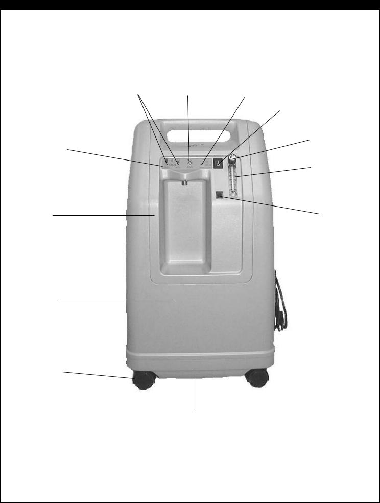
F I G U R E S , D I A G R A M S , A N D V I E W S
Figure 1 - Exterior Front View
OSD Indicator Lights |
Service Required |
(OSD units only) |
Light (Red) |
Light Panel
Oxygen
Outlet Port 
Bib
Front
Cover
Caster
Base
Power Light (green)
Power Switch
Flow Meter Knob
Flow Meter
Circuit
Breaker
LT-1928 |
22 |

F I G U R E S , D I A G R A M S , A N D V I E W S
Figure 2 - Exterior Side View
Front cover |
|
|
|
Rear cover |
|
|
|
Cabinet screw
Power
Cord Strap
Power Cord
Caster
Exhaust Grill
23 |
LT-1928 |

F I G U R E S , D I A G R A M S , A N D V I E W S
Figure 3 - Exterior Rear View
Cabinet Screws
Air |
|
|
|
Filter Door |
|
|
|||
Filter |
|
|
|
|
Communication Port (with cover removed)
Cabinet Screws
LT-1928 |
24 |

F I G U R E S , D I A G R A M S , A N D V I E W S |
||
Figure 4 - Interior Rear View (515ADS and 515ADZ) |
|
|
|
Bib Screws |
|
Accumulator Tank |
|
Intake |
|
|
Bacteria Filter |
|
|
Communication Port |
|
|
Ladder Clamp |
Pressure Exhaust Hose |
|
|
(Silicone) 1/2" ID |
|
|
|
|
Compressor |
Compressor Connector |
|
Motor Mount |
|
|
|
|
|
Compressor |
|
|
Mounting Plate |
Power Cord & |
Cooling Fan |
Mounting Plate Screw |
Strain Relief on |
|
|
115 volt units |
|
|
|
25 |
LT-1928 |

F I G U R E S , D I A G R A M S , A N D V I E W S
Figure 4A - Interior, Rear Lower View (515AKS and 515AKZ)
Compressor |
IEC Connector for |
Connector |
models 515AKS |
|
and 515AKZ |
|
|
LT-1928 |
26 |
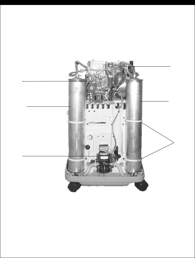
F I G U R E S , D I A G R A M S , A N D V I E W S
Figure 5 - Interior, Front View (515ADS and 515ADZ)
Wire Harness
PC Board
Right Sieve Bed
Left Sieve Bed
Sieve Bed
Cable Ties
Rotary
Directional
Air Valve
27 |
LT-1928 |
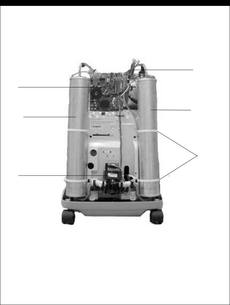
F I G U R E S , D I A G R A M S , A N D V I E W S
Figure 5A - Interior, Front View (515AKS and 515AKZ)
NOTE: Sieve beds shown are used only on models 515AKS and 515AKZ.
Wire Harness
PC Board
Right Sieve Bed
Left Sieve Bed
Sieve Bed
Cable Ties
Rotary
Directional
Air Valve
LT-1928 |
28 |
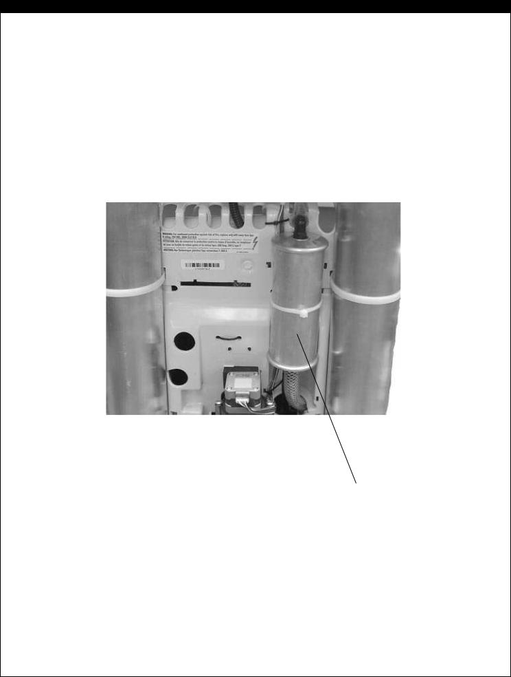
F I G U R E S , D I A G R A M S , A N D V I E W S
Figure 5B - Interior, Front View, Close Up (515AKS and 515AKZ)
Intake Silencer for models 515AKS and 515AKZ
29 |
LT-1928 |

F I G U R E S , D I A G R A M S , A N D V I E W S |
||
Figure 6 - Interior, Front Lower View (515ADS and 515ADZ) |
|
|
Bib Mounting |
|
|
Slot |
|
|
|
|
Rotary Valve |
|
|
Wire Harness |
Rotary |
|
Rotary Valve |
|
Mounting Cable |
|
Directional |
|
|
|
Ties |
|
Air Valve |
|
|
|
|
|
Left Sieve |
Compressor Mounting |
Right Sieve |
Bed Hose |
Plate Hex Nut |
Bed Hose |
LT-1928 |
30 |
|
 Loading...