

STUDIO 900 - STUDIO 90
STUDIO 900 - STUDIO 90
MIDI PEDALBOARD MP-1
MIDI PEDALBOARD MP-1
PLUS
PLUS
DATI TECNICI
CONNESSIONI
PROGRAMMAZIONE:
POSIZIONE DELLE OTTAVE
CANALE MIDI
CAMBIO PRESET
ENGLISH DEUTSCH ITALIANO
MIDI PEDALBOARD MP-1
Pag.
14
FEATURES
"
14
CONNECTIONS
"
"
"
TURN-ON DEFAULTS
15
OPERATING INSTRUCTIONS
15
BINARY LED DISPLAY
15
OCTAVE ASSIGNMENT
CHANNEL ASSIGNMENT
PROGRAM ASSIGNMENT
Page
"
"
"
"
"
"
38
DIE TECHNISCHEN DATEN
38
ANSCHLÜSSE
39
DIE PROGRAMMIERUNG:
1.0 OKTAVLAGE
39
2.0 MIDI-KANAL
3.0 WEITERSCHALTEN DER
39
KLANGFARBEN
40
40
Pag.
"
"
"
"
60
60
61
61
61
INDEX
CARATTERISTICHE
CONNESSIONI
STANDARD SETUP
PROGRAMMAZIONE
ELABORAZIONI MIDI
MIDI CONTROL NUMBER
Pag.
"
"
"
"
"
STUDIO 900
2
TECHNICAL DATA
2
CONNECTIONS
3
PROGRAM CHANGE
3
BANK CHANGE
4
CONTROL# COMMANDS
5
TOP PANEL
OPERATION
MIDI CONTROL NUMBER
ENGLISH DEUTSCH ITALIANO
Page
18
TECHNISCHE DATEN
"
18
HINWEISE
"
19
VERKABELUNG
"
19
BEDIENUNG
"
20
MIDI-KANAL
"
20
PROGRAMMWECHSEL
"
21
CONTROLLER
"
22
TRANSPONIERUNG
Pag.
"
"
"
"
"
"
"
42
43
44
45
46
48
49
50
CARATTERISTICHE
RESET GENERALE
COLLEGAMENTI
ACCENSIONE
USCITE MIDI
PARAMETRI E VALORI
PROGRAMMAZIONE:
SPLIT POINT
TRANSPOSE
OCTAVE
CHANNEL MIDI
PRESET
FOOT-SWITCH/PITCH &
MODULATION CONTROL
VEL. SENS. TOUCH
VEL. SENS. RELEASE
Pag.
"
"
"
"
"
"
"
"
"
"
"
"
"
STUDIO 90
6
INTRODUCTION
7
FEATURE LIST
7
CONNECTIONS
7
SWITCHIN ON - NOTE
7
SECTION I: GETTING STARTED
8
LET'S GET STARTED
PROGRAMS
PARAMETERS
9
SPLIT LEFT-SPLIT RIGHT
11
TRASPOSER
12
OCTAVE
12
CHANNEL MIDI
13
PRESET
FOOT-SWITCH CONTROL
13
VEL. SENSITIVITY
13
SECTION II: SAMPLE SET-UP
13
MIDI IMPLEMENTATION CHART
RESET P.
PLUS
Page
"
"
"
"
"
"
"
"
"
"
"
"
"
"
"
"
24
EIGENSCHAFTEN
24
GENERALPROGRAMMIERUNG
25
ANSCHLÜSSE
26
NETZANSCHLÜSSE
27
MIDI-AUSGÄNGE
27
PARAMETER UND WERTE
27
28
DIE PROGRAMMIERUNG:
28
SPLITPUNKTE
30
TRANSPOSE
30
OKTAVE
31
CHANNEL MIDI
31
PRESET
32
FUSSTASTER MODE
32
CONTROL
33
VEL. SENS. TOUCH
34
VEL. SENS. RELEASE
Pag.
"
"
"
"
"
"
"
"
"
"
"
"
"
52
53
53
53
53
54
55
57
58
58
59
59
59
59
STUDIO 900
Benvenuti nel mondo delle MASTERKEYBOARD FATAR.
La MASTERKEYBOARD STUDIO 900 è un Midi controller molto semplice e
versatile. Possiede un software non sofisticato, ma in grado di soddisfare le
esigenze del tastierista che vuole lavorare in modo veloce e con controlli Midi
sufficienti per un ottimo lavoro di musica live o di studio.
1) Collegare l'adattatore di tensione alla presa elettrica di rete (verificando che la
tensione dell'adattatore corrisponda alla tensione di linea). Collegare il cavo di
uscita dell'adattatore all'ingresso di alimentazione della MASTERKEYBOARD
(STUDIO 900 accetta come alimentazione 9V DC con polarità positiva [+] al centro
e necessita di una corrente minima di 200 mA).
2) Collegare il/i cavi Midi al vostro o ai vostri expanders o altri dispositivi Midi.
3) Attivare la MASTERKEYBOARD STUDIO 900 premendo il pulsante *POWER* e
si predisporrà nel modo *STANDARD SETUP* (vedi sotto).
CARATTERISTICHE TECNICHE:
La MASTERKEYBOARD STUDIO 900 si presenta con:
- Tastiera dinamica a 88 tasti pesati
- 4 Switches sul pannello di controllo
- 2 ruote di cui una Pitch Bend e l'altra programmabile.
- 18 dei tasti neri della master sono usati per funzioni speciali.
Sul retro troviamo:
- 2 uscite Midi parallele.
- Un jack input per il sustain
- Un jack input per il volume generale
- L'interruttore di alimentaziopne
- L'ingresso di alimentazione DC.
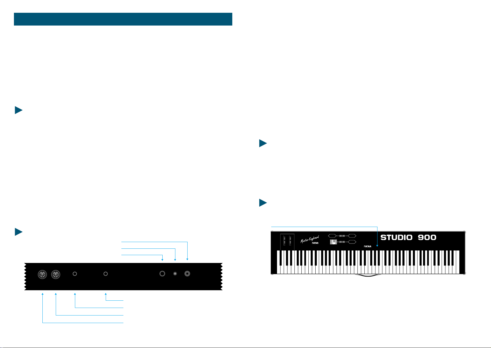
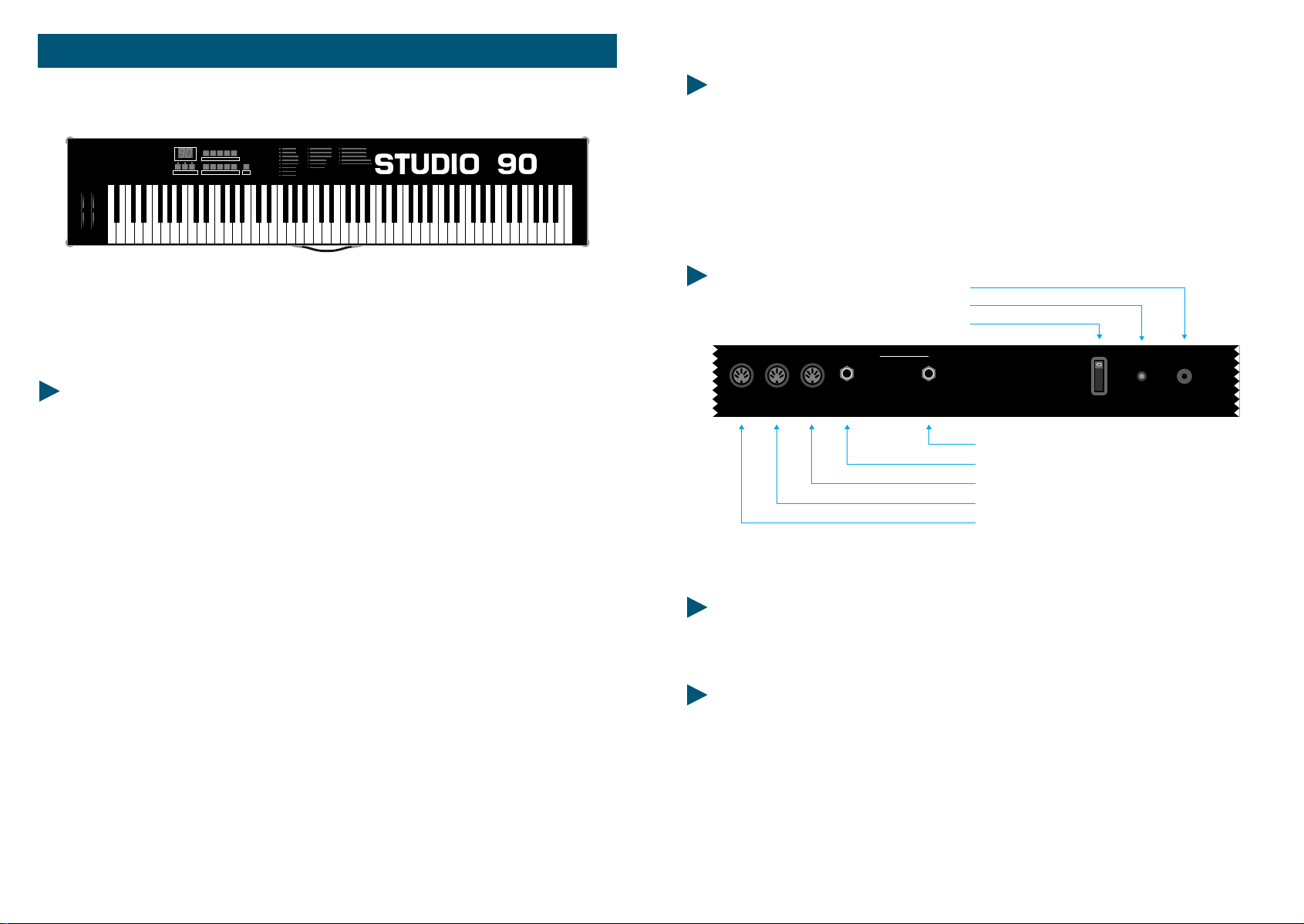
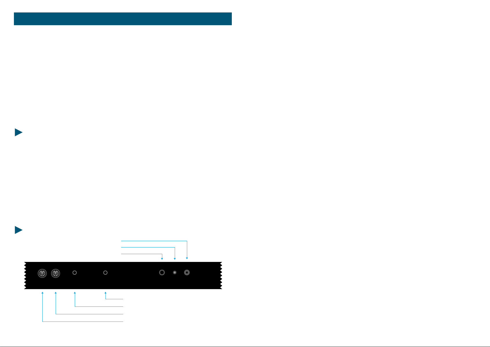
CONNESSIONI:
INPUT VDC
LED
SWITCH ON-OFF
MIDI OUTPUTS
1
SUSTAIN VOLUME
2
PEDAL VOLUME
FOOT-SWITCH SUSTAIN
MIDI OUT 2
MIDI OUT 1
POWER
9V DC 200mA
4)Se si ha la necessità di controllare il sustain e il volume, collegare agli appositi
jack, per il sustain un pedale con il contatto normalmente aperto (es: VFP1/10), per
il volume un pedale di controllo lineare con jack stereo (es: VP26).
STANDARD SETUP:
STUDIO 900 non ha memoria interna per storare dei preset, quindi all'accensione si
predisporrà automaticamente e sempre allo stesso modo:
- Tastiera unita 88 tasti
- Canale Midi base = 1
- Ruota destra programmabile = Modulation
- Transpose = 0
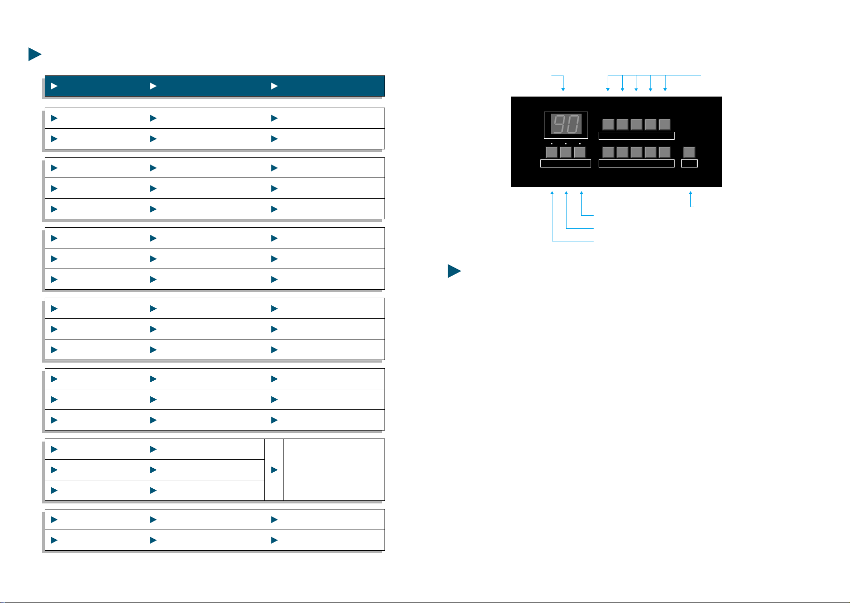
PROGRAMMAZIONE IN TEMPO REALE:
AFT PITCH MOD VOL. PAN 1234567890INCDECBANK
PROGRAM
Pitch
A
BY
AFT PITCH MOD VOL. PAN 1234567890 INC DEC BANK
TRANSPOSE
CHANNEL
CONTROL
Su pannello troviamo i seguenti switch:
*PROGRAM* = per inviare comandi di Program Change
*CHANNEL* = per inviare comandi di Canale Midi
*TRANSPOSE* = per inviare comandi di Trasposizione
*CONTROL#* = per inviare comandi di programmazione ruota destra.
2
STUDIO 900
STUDIO 900
3
Pitch
PROGRAM
A
TRANSPOSE
CHANNEL
CONTROL
ISTRUZIONI PER ELABORAZIONI MIDI:
A - Per trasmettere un Program Change, tenere premuto lo switch *PROGRAM* e
digitare il numero desiderato con i tasti neri etichettati con i numeri da 0 a 9 (o
usando i tasti *DEC* o *INC* per incrementare o decrementare di una unità).
Il Program Change è assunto quando lo switch *PROGRAM* viene rilasciato.
I Program Change sono numerati da 1 a 128 (Nota bene, alcuni expander
comprendono la numerazione da 0 a 127, quindi in quel caso si dovrà
incrementare di 1 il numero desiderato. Se si ha necessità di un numero superiore a
128, l'unità può convertire il numero nel corretto banco riconoscibile dal
dispositivo Midi in ricezione.
Per selezionare un nuovo banco di programmi, tenere premuto lo switch
*PROGRAM*, premere il tasto nero etichettato *BANK* e digitare il numero
desiderato con i tasti neri etichettati da 0 a 9. Il Bank Change è assunto quando lo
switch *PROGRAM* viene rilasciato.
B - Per cambiare il canale Midi di trasmissione, tenere premuto lo switch
*CHANNEL* e digitare il numero di canale Midi desiderato (da 1 A 16), il messaggio
di cambio canale avverrà quando lo switch *CHANNEL* viene rilasciato.
C - Per ottenere una trasposizione, tenere premuto lo switch *TRANSPOSE* e
(tenendo presente che la nota di riferimento è il DO (C) centrale), premere la nota
desiderata che sarà posizionata alla locazione del DO centrale.
Esempio: Se si vuole trasportare la tonalità di 5 semitoni verso l'alto, dopo aver
premuto lo switch *TRANSPOSE*, si dovrà premere il FA subito superiore al Do
centrale.
LISTA DEI MIDI CONTROL NUMBER:
NUMERO DI CONTROLLO FUNZIONI DI CONTROLLO
0 Bank
1 Modulation
2 Breath controller
3 Undefined
4 Foot controller
5 Portamento rate
6 Data Entry MSB
7 Volume
8 Balance
9 Undefined
10 Pan
11 Expression
12- 15 Undefined
16 Gen'l Purpose #l
17 Gen'l Purpose #2
18 Gen'l Purpose #3
19 Gen'l Purpose #4
20- 31 Undefined
32 Bank
33- 63 Least significant byte for values 0 to 31
64 Sustain (damper)
65 Portamento On/ Off
66 Sostenuto
67 Soft Pedal
68 Undefined
69 Hold 2
70 - 7 Undefined
80 Gen'l Purpose #l
81 Gen'l Purpose #2
82 Gen'l Purpose #3
83 Gen'l Purpose #4
84 - 91 Undefined
92 Tremolo Depth
93 Chorus Depth
94 Detune
95 Phaser Depth
96 Data increment
97 Data decrement
98 - 121 Undefined
122 Local control On/Off
123 All Notes Off
124 Omni Off
125 Omni On
126 Mono On - Poly Off
127 Poly On - Mono Off
D - Per assegnare un nuovo controllo alla ruota destra, premere lo switch
*CONTROL#* e premere uno dei tasti etichettati con AFTERTOUCH, PITCH, MOD,
VOL, PAN; oppure per assegnare un controllo diverso da quelli previsti, digitare il
numero di controllo Midi tramite i tasti da 0 a 9 il controllo verrà assegnato alla
ruota destra quando lo switch *CONTROL* sarà rilasciato.
4
STUDIO 900
NOTA BENE:
Ricordare che ogni volta che si vuole digitare un numero durante la fase di
programmazione, esso può essere immesso con i tasti neri etichettati da 0 a 9
oppure premendo i tasti contrassegnati con *INC* o *DEC* per incrementare o
decrementare il valore corrente del parametro sul quale si vuole intervenire.
STUDIO 900
5
Param. Value Prog.
CARATTERISTICHE
- Alimentazione: 9 VDC 500 mA
- 88 Tasti pesati
- Range Dinamico (00-99)
- Controllo dinamico al rilascio (00-99)
- Misure originali di un vero pianoforte
- Tocco dinamico come un vero pianoforte
- Due punti di divisione della tastiera (Split Point)
- Trasposizione per semitoni
- Trasposizione per ottave
- Tre uscite midi
- Pedale di controllo Foot/Switch
- Pedale cambio programmi
- Controlli di Pitch e Modulations
- 16 Canali MIDI esterni a scelta
- 100 programmi
- Display di controllo
- Flightcase
- Cabinet
STUDIO 90
1
2345
Enter
67890
PLUS
RESET GENERALE
Spegnere la tastiera.
Tenere premuti i tasti "ENTER" e "1" della tastiera numerica.
S
U
L
P
Sempre tenendo premuti i suddetti tasti, riaccendere la tastiera.
Importante: una volta resettata la tastiera, tutti i programmi vengono cancellati
ed entra in funzione un programma di default.
COLLEGAMENTI
INPUT VDC
LED
POWER
1
MIDI OUT
23
FOOT-SWITCH
MIDI
CONTROL
PROGRAM
CHANGE
POWER
ON
OFF
9V DC 200mA
FOOT-SWITCH PROGRAM CHANGE
FOOT-SWITCH MIDI CONTROL
MIDI OUT 3
MIDI OUT 2
MIDI OUT 1
Fig. 1
ACCENSIONE
Per accendere lo strumento, collegare il cavo di alimentazione nell'ingresso "LINE".
Per capire bene le connessioni, vedi il Fig. "1".
USCITE MIDI
Le uscite MIDI sono tre per la STUDIO 90 Plus. Queste sono collegate in parallelo, così
da permettere all'utente di formare più di una catena MIDI.
6
STUDIO 90 Plus
STUDIO 90 Plus
7
PARAMETRI E VALORI DELLA STUDIO 90 Plus
PARAMETRO FUNZIONE VALORE
PARAMETRO FUNZIONE VALORE
00 Split Sinistro 00-88
01 Split Destro 00-88
02 Transposer 1 00-11
03 Transposer 2 00-11
04 Transposer 3 00-11
05 Octave 1 70-00-07
06 Octave 2 70-00-07
07 Octave 3 70-00-07
08 Midi out 1 01-16
09 Midi out 2 01-16
10 Midi out 3 01-16
11 Preset 1 00-99
12 Preset 2 00-99
13 Preset 3 00-99
14 FT.SW. Control 1
15 FT.SW. Control 2
16 FT.SW. Control 3
17 Vel. Sens. Touch 00-99
18 Vel. Sens. Release 00-99
00=off FS/Mod
01=on FS off Mod
02=off FS on Mod
03=on FS Mod
POSSIBILITA' DI PROGRAMMAZIONE DELLA STUDIO 90 Plus
TASTI NUMERICIDISPLAY
1
Param. Value Prog.
2345
67890
Enter
TASTO PROGRAMMA
TASTO VALUE
TASTO PARAMETRI
SPLIT POINT - Punto di divisione (Parametro 00 e 01).
TASTO ENTER
La tastiera Studio 90 Plus, ha due punti di divisione completamente liberi di essere
programmati. Su questo terreno, ci sono parametri contrassegnati con 1,2 e 3. Il
numero uno è sempre la zona di sinistra della tastiera, il due è il centro e il tre la
parte destra. Se è collocato solo il punto di divisione sinistro, sono attive la zona 1
(sinistra) e la zona 2; se è fissato il punto di divisione destro, sono attive la zona 2
(a sinistra) e la zona 3 (destra).
Se il parametro 00 (Punto di divisione sinistro) è collocato sul valore 01 e il
parametro 01 è collocato sul valore 87, l'intera tastiera può essere suonata con un
solo suono, poiché è solo la zona 2 della tastiera in funzione attiva.
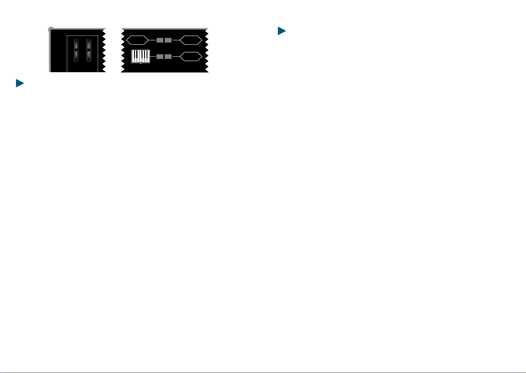
Accanto a questo primo orientamento "normale" ci sono ancora due diverse
possibilità.
Fig. B la parte sinistra e destra della tastiera si lasciano suonare nello stesso
orientamento. La zona centrale può suonare così tutti i tre canali MIDI
contemporaneamente;
Fig. C collocare la voce sopra il parametro 03 (transposer 2) e lo 06 (ottava 2). Porre il
punto di divisione destro e sinistro sullo stesso tasto. La tastiera verrà divisa in due
parti; destra e sinistra, modificabili con i parametri contrassegnati con i numeri 1 e
3, mentre contemporaneamente, tutta la tastiera potrà avere un suono di sovrapposizione modificabile con i parametri contrassegnati dal numero 2.
8
STUDIO 90 Plus
STUDIO 90 Plus
9
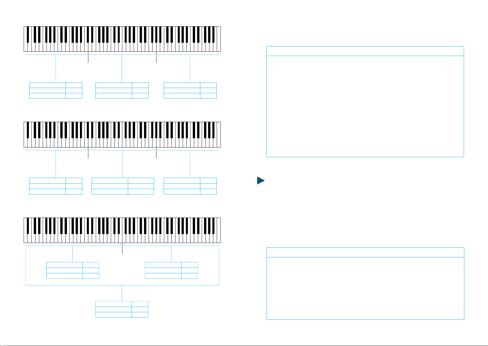
Esempio: Nel programma N. 12 il punto di divisione sinistro si trova sul tasto
17 e il punto di divisione destro nel tasto 42.
A
B
CHANNEL MIDI 1
TRANSPOSER 1
OCTAVE 1
CHANNEL MIDI 1
TRANSPOSER 1
OCTAVE 1
PAR. 08
PAR. 02
PAR. 05
PAR. 08
PAR. 02
PAR. 05
SPLIT 1
PAR. 00
SPLIT 2
PAR. 01
CHANNEL MIDI 1-2-3
TRANSPOSER 2
OCTAVE 2
CHANNEL MIDI 2
TRANSPOSER 2
OCTAVE 2
PAR. 09
PAR. 03
PAR. 06
PAR. 08-09-10
PAR. 03
PAR. 06
SPLIT 2
PAR. 01
SPLIT 1
PAR. 00
CHANNEL MIDI 3
TRANSPOSER 3
OCTAVE 3
CHANNEL MIDI 3
TRANSPOSER 3
OCTAVE 3
PAR. 10
PAR. 04
PAR. 07
PAR. 10
PAR. 04
PAR. 07
Operazione Tasto Display Cosa succede
1 PROG. tasto programma attivato
212 lampegg. chiamare numero programma
3 ENTER 12 il programma 12 è attivato
4 PARAM. tasto parametro attivato
500 lampegg. split-point sinistro attivato
6 ENTER 00 parametro attivo
7 VALUE attivare il tasto value
817 lampegg. chiamato split-point
9 ENTER 17 split sinistro sul tasto 17
10 PARAM. 00 attivato il tasto parametro
11 01 lampegg. split-point destro attivato
12
13
14
15
ENTER
VALUE
42
ENTER
TRANSPOSE 1, 2, 3 (Parametri 02, 03, 04)
01
lampegg.
42
parametro attivo
attivare il taso value
assegnato split-point
split-point attivo
Con questo parametro, potete transporre i vari strumenti fino ad un massimo di 11
semitoni, così da poter intonare uno strumento ad un altro qualora ce ne fosse la
necessità, oppure per ottenere effetti di terza e quinta suonando sempre nella
stessa tonalità.
C
10
CHANNEL MIDI 1
TRANSPOSER 1
OCTAVE 1
STUDIO 90 Plus
PAR. 08
PAR. 02
PAR. 05
SPLIT 1-2
PAR. 00-01
CHANNEL MIDI 2
TRANSPOSER 2
OCTAVE 2
PAR. 09
PAR. 03
PAR. 06
CHANNEL MIDI 3
TRANSPOSER 3
OCTAVE 3
PAR. 10
PAR. 04
PAR. 07
Esempio: Nel programma N. 23 la zona sinistra della tastiera dovrà essere
trasportata di 4 mezzi toni.
Operazione Tasto Display Cosa succede
1 PROG attivato tasto programma
223 lampegg. assegnato num. programma
3 ENTER 23 programma 23 attivato
4 PARAM. attivato il tasto parametro
502 lampegg. assegnato il parametro
6 ENTER 02 parametro attivato
7 VALUE attivare il tasto value
804 lampegg. assegnato il valore
9 ENTER 04 trasposizione avvenuta
STUDIO 90 Plus
11

OCTAVE 1, 2, 3 (Parametri 05, 06, 07)
Con questo parametro si possono effettuare trasposizioni per ottave. E' possibile
trasportare il suono fino a sette ottave sopra e sette sotto.
PRESET 1, 2, 3 (Parametri 11, 12, 13)
La scelta dei suoni dei vari expanders e strumenti collegati alla STUDIO 90 Plus,
avviene attraverso questi parametri, che offrono una possibilità di scelta tra 100
suoni (00-99).
Esempio: Nel programma N. 02 la zona sinistra della tastiera deve essere
trasportata di 2 ottave sopra, la destra dovrà essere abbassata di 4 ottave. La zona
centrale rimane uguale. Attenzione, i due punti di divisione rimangono invariati.
Operazione Tasto Display Cosa succede
1 PARAM. tasto parametro attivato
205 lampegg. assegnare il parametro
3 ENTER val. prec. parametro in funzione
4 VALUE val. prec. attivare il tasto value
502 lampegg. assegnato il valore dell'ottava
6 ENTER 02 valore memorizzato
7 PARAM tasto parametro attivato
807 lampegg. assegnare il parametro
9 ENTER val. prec. parametro in funzione
10 VALUE val. prec. attivare il tasto value
11 40 lampegg. assegnato il valore dell'ottava
12 ENTER 40 valore memorizzato
CHANNEL MIDI 1, 2, 3 (Parametri 08, 09, 10)
Questo Parametro ci permette di assegnare il canale MIDI di trasmissione da 1 a 16;
ovviamente uno per ogni parte di tastiera.
Esempio: Nel programma N. 17 la zona sinistra della tastiera dovrà suonare il
canale MIDI 3.
Operazione Tasto Display Cosa succede
1 PROG attivato tasto programma
207 lampegg. assegnato num. programma
3 ENTER 07 programma 07 attivato
4 PARAM. 08 attivato il tasto parametro
508 lampegg. assegnato il parametro
6 ENTER val. prec. parametro in funzione
7 VALUE val. prec. attivato il tasto value
803 lampegg. assegnato il canale MIDI
9 ENTER 03 canale MIDI memorizzato
Esempio: Nel programma N. 47 si dovrà mettere la parte centrale della tastiera con
il suono 16. Dopo aver chiamato il programma che ci interessa, si procede:
Operazione Tasto Display Cosa succede
1 PARAM. attivato tasto parametro
212lampegg. assegnato num. parametro
3 ENTER val. prec. parametro attivo
4 VALUE val. prec. attivare il tasto value
516lampegg. assegnato il valore
6 ENTER 16 valore memorizzato
FOOT-SWITCH/PITCH & MODULATIONS CONTROL 1, 2, 3 (Parametri 14, 15, 16)
Questa è la funzione che ci permette di attivare o disattivare sia il controllo del
Sustain (Foot-Switch) che delle due rotelline di controllo Pitch e modulations.
Esempio: vogliamo attivare il Foot-Switch e disattivare le ruote di modulazione
nella parte destra della tastiera nel programma 63. Come abbiamo già visto ci si
porta sul programma 63 con le solite operazioni, si attiva il tasto VALUE come
sappiamo gia fare infine si memorizza il nuovo valore intermedio che in questo
caso sarà "01".
VEL SENS. TOUCH (Parametro 17)
Con questa funzione, possiamo regolare il tocco dinamico della tastiera; avendo a
disposizione un range molto vasto, è possibile regolare la dinamica giusta sia per il
suono che per la tecnica del musicista. Normalmente è posizionato ad un valore
intermedio, che si adatta sia alla tecnica del pianista che del tastierista.
VEL. SENS. RELEASE (Parametro 18)
Questo è invece il controllo dinamico al rilascio, ovvero se volete ottenere degli
effetti quando lasciate il tasto, potete controllare la velocità alla quale volete che
l'effetto entri in funzione.
E' chiaro che questo parametro funzionerà soltanto se lo strumento collegato
accetta questo comando.
12 STUDIO 90 Plus
13STUDIO 90 Plus
MIDI PEDALBOARD MP-1
OCTAVE CH. MIDI
1248
PRESET
MP 1
CHANNEL MIDI
OCTAVE
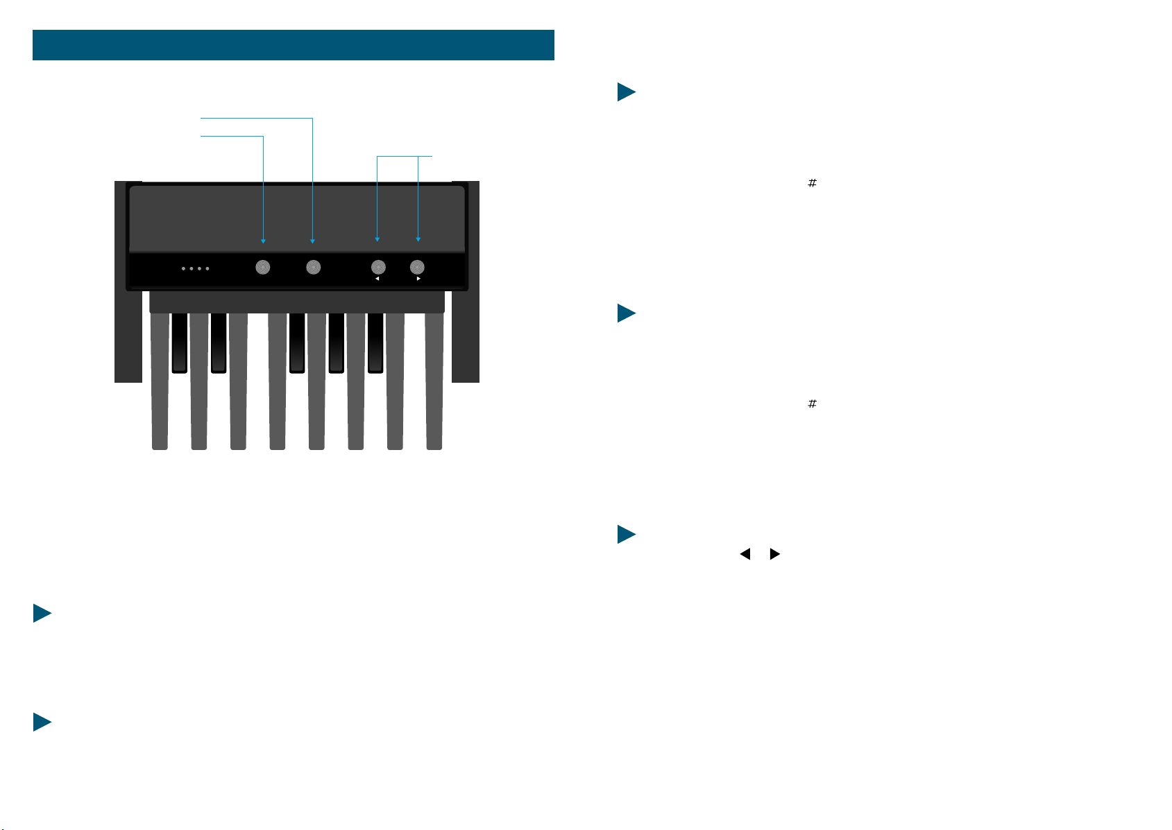
POSSIBILITA' DI PROGRAMMAZIONE DELLA MIDI PEDALBOARD
POSIZIONE DELLE OTTAVE
Dopo l'attivazione del tasto "OTTAVA" premendo semplicemente uno dei tasti
della pedaliera, si decide l'ottava da assegnare:
PRESET
- DO = Ottava più bassa
- DO = Ottava sopra
- RE = Ottava sopra
- e così via fino ad arrivare all'ultimo
- DO = Ottava più alta.
CANALE MIDI
Dopo l'attivazione del tasto "CH. MIDI", si assegna il canale MIDI premendo uno
dei tasti della pedaliera.
- DO = Canale MIDI 1
- DO = Canale MIDI 2
- RE = Canale MIDI 3
- fino ad arrivare all'ultimo tasto
- DO = Canale MIDI 13
Con la MIDI PEDALBOARD, avete il vostro sistema MIDI non solo ingrandito su di
una pedaliera di tredici tasti, ma potete, per esempio, richiamare tutti i suoni che
volete da un qualsiasi strumento MIDI ad essa collegato con la possibilità di scelta
di un canale MIDI. La MIDI PEDALBOARD, è stata costruita affinché tutte le operazioni possano essere effettuate facilmente ed interamente con i piedi.
DATI TECNICI
- 13 Tasti
- Posizione delle ottave completamente libera
- Canali MIDI completamente liberi
- Cambio Presets
CONNESSIONI
- Alimentazione 9 o 12 Volts
- MIDI OUT
14
MIDI PEDALBOARD
CAMBIO PRESETS
Con i due tasti e , si lasciano passare avanti e indietro e vari suoni fino ad
arrivare a quello desiderato. Ovviamente il Preset cambierà soltanto nello strumento corrispondente al canale MIDI programmato nella MIDI PEDALBOARD.
Esempio: Vogliamo suonare la MIDI PEDALBOARD con il canale MIDI 11,
scegliamo il suono desiderato, ed essendo di tre ottave più basso lo alziamo di tre.
Premere il pulsante "CH. MIDI", quindi suonare il tasto "LA"; ora con i tasti < e >
andiamo alla ricerca del suono. Ora che abbiamo il suono giusto e il canale MIDI
memorizzato, aggiustiamo il Preset trasponendolo di tre ottave sopra: premiamo il
mulsante "OTTAVA" quindi il tasto "RE".
MIDI PEDALBOARD
15
STUDIO 900
Welcome to the world of the Fatar Studio Series Keyboard Controllers.
Congradulations on purchasing the ST-900, one of the finest master keyboard
controllers in the world today. The action is a result of many years of design and
engineering to bring the musician a keyboard mechanism that feels as close to an
acoustic piano as possible.
The Studio-900 is the perfect choice for a musician looking for a simple yet
versatile keyboard controller to produce quality results for the live or studio
environment
.
l) Connect the AC adapter cable to the power input jack, in the back of the
controller, located next to the power switch. See Figure #1.
Make sure that the AC adapter corresponds to the correct voltage output. The
Studio 900 will accept an adapter that has a rating of 9V DC with a positive polarity
tip and has a minimum current of 200 ma.
2) Connect MIDI cable from the ST-900 s MIDI outputs, (each output can handle up
to four synthesizers, modules, or effect devices) to the MIDI input on your sound
sources. Set your sound sources to the desired MIDI channelsby the ST-900. Each
channel would normally be assigned to a different sound or effect. Since the ST9OO has only one zone, you can only program one of the16 channels at a time.
Make sure that your sound source is properly assigned to the channel you are
sending on.
TECHNICAL CHARACTERISTICS:
* 88 weighted keys with hammer action
* One zone
* Velocity Sensitive
* Pitch Bend Wheel and Programmable Wheel
* Two Parallel MIDI Outputs
* Sustain Input Jack
*Volume Input Jack
* Program change, MIDI Channel, Transpose, Programmable wheel (Volume, Pan,
Aftertouch, Pitch, Modulation) etc.
* External Adapter 9V DC 500ma included
* Dimensions: 51 3/4" X 13 3/4" X 4 1/2" 48 lbs.
CONNECTIONS:
INPUT VDC
LED
SWITCH ON-OFF
MIDI OUTPUTS
1
SUSTAIN VOLUME
2
POWER
PEDAL VOLUME
FOOT-SWITCH SUSTAIN
MIDI OUT 2
MIDI OUT 1
9V DC 200mA
Figure #1.
To select a base channel hold the [CHANNEL[ switch and enter the channel number
(l through 16) by depressing the appropriate black numbered key (0-9). The
function switch must be released after the black number keys. At this point the ST900 is sending on that channel.
Program change:
A program change command allows you to change the sound on your sound
source from the ST-900. The program change will be sent on whichever MIDI
channel the ST-900 is currently set. Program changes are numbered 1 through 128.
You may notice, depending on the sound source, that a program change of 1 will
show up on your sound source as 0. This is not a problem, since MIDI is not
completely standard between manufacturers. Thank the heavens that there are only
a few anomalies like this between the manufacturers.
To issue a program change, hold the [PROGRAM] switch and enter the desired
number on the numbered black keys with the appropriate program number or use
the [INC]/ [DEC] (increment/ decrement) keys. If a number greater than 128 is
entered, it will wrap around to the beginning.
Bank change:
Some sound sources today, especially found on computer sound cards, have a
feature called bank select. The MIDI specification calls for bank numbers 1 through
16384. Once you have selected your bank you are able to select a program change
(l through 128).
18 STUDIO 900
19STUDIO 900

To select a bank of prograrns, hold the [PROGRAM ]switch, press [BANK] key, and
enter the appropriate bank number using the O through 9 keys. The bank
command will be transmitted when the [PROGRAM] switch is released. The [INC]/
[DEC] keys may be used instead of entering the bank number.
Control # Commands:
There are 127 controller functions that are rnade up of continuous and switch
control commands. See Figure # 3. The most commonly used controllers are
aftertouch, pitch, modulation, volume and pan. Many expensive keyboard
controllers offer aftertouch, which allows expressive control of sound sources. The
ST-900 allows the same expression via [WHEEL A]. Aftertouch, pitch,
(1 through 16). Refer to the sound source s owners manual for this procedure.
3) Connect a momentary footswitch, which circuit is normally open, to the sustain
input jack clearly marked SUSTAIN located next to the MIDI jacks. We recommend
a VFP-1/10 (piano-like sustain pedal) available from Music Industries Corp.
Pitch
PROGRAM
A
TRANSPOSE
CHANNEL
CONTROL
To the right of the wheels there are four switches. These switches are used for
program change, channel assignment, transposition and programmable wheel
assignment. Eighteen black keys on the keyboard are used for special MIDI
functions. The first five are used for [WHEEL A]. Notice, [AFT], [PITCH], [MOD],
[VOL] and [PAN]. These keys represent aftertouch, pitch, modulation, volume and
panning. The next 10 black keys represent a numeric key pad for program changes
and channel assignments. The following two black keys are used for increment and
decrement of a program change. [INC]/[DEC] will also change the controller
number. The last key is used for selecting a bank. More on this in the next section.
4) Connect a control voltage pedal for volume in the jack clearly marked VOLUME
located next to the sustain jack. We recommend a VP-26 (expression pedal)
available from Music Industries Corp.
Once all connections are in place, press the power switch to the ON position.
TOP PANEL:
AFT PITCH MOD VOL. PAN 1234567890INCDECBANK
PROGRAM
Pitch
A
BY
AFT PITCH MOD VOL. PAN 1234567890 INC DEC BANK
TRANSPOSE
CHANNEL
CONTROL
Figure #2.
See Figure #2. You will notice on the left a dedicated pitch and a programmable
second wheel, rnarked [WHEEL A]. With [WHEEL A] you may assign aftertouch,
pitch, modulation, volume and pan as well as any controller (O - 127).
OPERATION:
Getting around the ST-900 is very simple. However, you must know certain basic
MIDI theory before it can make sense.
Base Channel:
There are l6 different channels in the MIDI specification that can be accessed
modulation, volume and pan can be accessed by the corresponding black keys,
,while all the remaining control functions can be accessed by the number or
[INC]/[DEC] keys.
To assign the programmable wheel press and hold the Control # switch. Enter the
desired controller number on the numbered black keys, or use the [INC] / [DEC]
keys, then release the control # switch. Look at the list in figure #3, try them out. If
you are having problems, chances are the sound source does not have that feature.
Sometimes you might get undesirable results. At this point it might be best to reset
your sound source (see sound sources owners manual) and shut off the ST-9OO,
then turn it back on again. This will reset the ST-900 to base channel #1, the control
wheel to modulation and no transposition.
20 STUDIO 900
21STUDIO 900

CONTROLLER NUMBER CONTROLLER FUNCTION
0 Bank
1 Modulation
2 Breath controller
3 Undefined
4 Foot controller
5 Portamento rate
6 Data Entry MSB
7 Volume
8 Balance
9 Undefined
10 Pan
11 Expression
12- 15 Undefined
16 Gen'l Purpose #l
17 Gen'l Purpose #2
18 Gen'l Purpose #3
19 Gen'l Purpose #4
20- 31 Undefined
32 Bank
33- 63 Least significant byte for valuesO to 31
64 Sustain (damper)
65 Portamento On/ Off
66 Sostenuto
67 Soft Pedal
68 Undefined
69 Hold 2
70 - 7 Undefined
80 Gen'l Purpose #l
81 Gen'l Purpose #2
82 Gen'l Purpose #3
83 Gen'l Purpose #4
84 - 91 Undefined
92 Tremolo Depth
93 Chorus Depth
94 Detune
95 Phaser Depth
96 Data increment
97 Data decrement
98 - 121 Undefined
122 Local control On/Off
123 All Notes Off
124 Omni Off
125 Omni On
126 Mono On - Poly Off
127 Poly On - Mono Off
Figure #3
Refer to a MIDI technical handbook for further information on these controller
functions.
Transposition:
Sometimes a player may not be able to play in a certain key. At these times the
[TRANSPOSE] switch will be invaluable. For example, if you need to change from
the key of C major to the key of Eb major, you can still play the C major keys, but
what you hear would be Eb major.
To transpose the keyboard, hold the [TRANSPOSE] switch and press the desired key on the
keyboard above or below middle C. The result will be a new key change when the C major
keys are played. Your range is limited to 24 half steps up and 24 half steps down.
If there are any technical problems that relate to the ST-900 only, please contact Music
Industries Corp. 800-431-6699. Best of luck!!!
This equipment has been tested and found to comply with the limits for a Class B digital
device, pursuant to Part 15 of the FCC rules. These limits are designed to provide
reasonable protection against harmful interference in a residential installation. This
equipment generates, uses, and can radiate radio frequency energy and, if not installed
and used in accordance with the instructions, may cause interference to radio
communications. However, there is no guarantee that interference will not occur in a
particular installation. If this equipment does cause harmful interference to radio or
television reception, which can be determined by turning the equipment on and off, the
user is encouraged to try to correct the interference by one or more of the following
measures:
• Reorient or relocate the receiving antennas.
• Increase the separation between the equipment and the receiver.
• Connect the equipment into an outlet on a circuit different from that to which the
recelver
is connected.
• Consult the dealer or an experienced radio/TV technician for help.
NOTE: Use of shielded power and interface cables with this equipment is required in order
to ensure compliance with FCC specifications.
CAUTION: Changes or modifications to this equipment not expressly approved by the
manufacturer responsible for compliance could void the user's authority to operate the
equipment.
It is recommended that only FCC class B certified devices be used with this equipment.
Operation of Class A equipment in a residential area is likely to cause harmful interference
in which case the user will be required to correct the interference at his or her own
expense.
22 STUDIO 900
23STUDIO 900

STUDIO 90
PLUS
1
Param. Value Prog.
2345
67890
Enter
Thank you for purchasing the FATAR Studio-90 Plus, the finest feeling master controller on the
market today. The action is a result of many years of engineering that went into the keyboard
mechanism. There are actually hammers that strike a surface that simulates a piano string.
The FATAR Studio-90 Plus master controller is very simple to operate once you understand its
capabilities. Even though the controller seems to be always in split mode, you can layer or split
one, two, or three sounds across the entire length of the keyboard. However, you must be aware of
the specific use of each parameter to get the desired results.
FEATURE LIST: The following is a feature list of the ST-90 Plus master keyboard controller.
Power Supply: 9 VDC 500mA
88 Note Weighted Hammer Action Keys
Key measurements like a real piano
Dynamic Range (00-99)
Velocity Sensitivity Release (00-99)
Three Zones Programmable
Half-tone transposition
Octave transposition
Three MIDI Outputs
Foot-Switch Control
Program Change Footswitch
Pitch and Modulation Wheels
Outputs on all 16 MIDI Channels (three channels at one time)
100 Performance Programs (00-99)
Two digit numeric display
Beautiful Cabinet Design
Also available in sturdy case road case
S
U
L
P
CONNECTIONS:
INPUT VDC
LED
POWER
1
MIDI OUT
23
FOOT-SWITCH
MIDI
CONTROL
PROGRAM
CHANGE
POWER
ON
OFF
FOOT-SWITCH PROGRAM CHANGE
FOOT-SWITCH MIDI CONTROL
MIDI OUT 3
MIDI OUT 2
MIDI OUT 1
9V DC 200mA
fig. #1
The Studio-90 Plus can be supplied with a road case or with a beautiful designed
cabinet. All the functions are the same, but cosmetically they are quite different.
The following will explain the difference between the two regarding the back
pannel.
Look at figure #1. It shows the back panel of the ST-90 Plus built into a road case.
Note its three midi outputs. Each output sends out identical information. You can
connect four midi sound sources per output, giving you up to twelve sources to
choose from. NEVER CHAIN MORE THAN FOUR MIDI DEVICES PER OUTPUT,
THIS CAN CAUSE SOME DELAYS. If you need more outputs, purchase a thru-box.
Located to the right of the midi outputs you will find a 1/4" phone input jack for a
foot switch sustain pedal. We recommend a Music Industries PS-10 or a VFP-10
(optional) sustain pedal for this application. We will review the sustain capabilities
later on in the next section. To the right of the sustain jack is another 1/4" phone
input jack for program advance. You will also review this function later on.
Located to the right of the 1/4" jacks you will find the power switch. To the right of
power switch is the three pole line cord input and finally the fuse holder. Use a 1
AMP 250V GGS 5 X 20mm when replacing the fuse.
24 STUDIO 90 Plus
25STUDIO 90 Plus

Look at figure #2 and #3. The functions are the same, but the location of the midi
outs and foot switch controls are separated from the power section. You will find
this configuration on the ST-90 Plus in the cabinet.
MIDI OUT
FOOT-SWITCH
fig. #2
1
23
POWER
ON
MIDI
CONTROL
9V DC 200mA
PROGRAM
CHANGE
fig. #3
OFF
Note: If you want merging capabilities with the Studio-90 Plus, you must use a
merge box. A good merge box we recommend is the Pocket Merge from Anatek
Microcircuits, Inc. North Vancouver, BC, CANADA.
SWITCHING ON:
To power on the instrument, connect the supplied power cable into "LINE" input
and flip the power switch on. Ever time you power up, program 00 will illuminate
on the LEDs.
NOTE: Studio-90 Plus RESET PROCEDURE:
If there is ever a time when the Studio-90 Plus acts up in a strange way due to an
electrical spike, a reset procedure may be necessary. Turn off power switch. Press
switches "ENTER and "1" down together. Turn on power and release "ENTER and
"1" after two seconds.
THIS PROCEDURE WILL CANCEL ALL PREVIOUS PROGRAMS AND DEFAULTS UNIT TO
FACTORY PRESETS. MAKE SURE YOU WRITE DOWN ALL IMPORTANT PATCH
PARAMETERS BEFORE MOVING ON TO CREATE ANOTHER PROGRAM. THERE IS A
BLANK PARAMETER CHART IN THE BACK OF THIS MANUAL. MAKE COPIES AND
BACK UP YOUR PROGRAMS ON THIS CHART. THIS IS JUST GOOD ADVICE.
SECTION I: GETTING STARTED
In this section we will explore the possibilities of the Studio-90 Plus in its entirety.
Do not skip any pages. Since each function depends on a previous parameter, it is
probably best to read carefully from here on out.
LET'S GET STARTED
In this section you should get ready for hands on experience. Plug in one end of a
midi cable to the output jack of the controller. Plug the other end into the midi
input of your sound module. For the first application, even if you have a multitimbral module, please set a piano or any other sound that you are comfortable
with to channel number one. (Multi-timbral means receive on more than one
channel at once.) The first application will only deal with channel number one. As
you progress you will be adding channels for different keyboard sound
combinations. At this time you should have your amplification set up as well. Any
other questions dealing with equipment set up, refer to their respective manuals.
Once everything is plugged in, power up your system in this order; controller,
sound modules, effects, mixer, EQ, and amplifier. This procedure will eliminate
any potential hazards to your system.
To program the controller properly you must understand in what sequence to push
the buttons to get the desired result. Let's take a look at the program function key
located under the two LEDs.
PROGRAMS:
The Studio-90 Plus is equipped with 100 programs, represented numerically
between numbers 00 and 99. In order to get from one program to another you
must press the buttons in a particular sequence. First, enter program mode by
pressing the button marked (prog.). Do this now. A light will illuminate at this
time underneath the program button, (when the unit is turned on, the program
light will already be illuminated) then enter a program number by pressing two of
the numeric keys. (Example, enter program 00, program 05 or any other desired
program up to 99).
At this point the numeric LED will flash, then you must press the ENTER* button
located to the right of the numeric key pad. This process will lock the desired
program into a current working memory location. Do this a couple of times so you
26 STUDIO 90 Plus
27STUDIO 90 Plus

can get the feel of moving through programs. (You will find that the ENTER button
must be pressed every time you want a function to work properly regardless what
you are attempting to do.) Another way to advance programs, is to use a foot
switch plugged into the program change jack, located on the back of the controller.
This will advance the programs in numerical order only.
PARAMETERS:
Now you can start programming parameters within a program. Let us start by first
picking a program, let's try program 00. If you're not sure how to do this, just
reread the last paragraph. OK, now that you are there, you will need to address the
parameters and see how they work.
Using the parameters on the Studio-90 Plus is easy once you get a handle on it. If
you take a look at top of the controller you will see a listing of nineteen
parameters, starting from 00 to 18. In order to access these parameters, press the
parameter (param.) button located on the lower left below the two LEDs. Please
do this now. You will notice that a red light will illuminate under that parameter
button. Now we will choose our first parameter.
SPLIT LEFT-SPLIT RIGHT:
The Studio-90 Plus has two split points represented by parameter 00 (SPLIT LEFT),
and parameter 01 (SPLIT RIGHT). You can assign these split points any where on
the keyboard. These parameters will allow you to have the controller operate in
single mode, split mode or layer mode. For now operate the controller in single
mode (one sound across the keyboard). In the next section there will be examples
of split and layer mode.
* Note: Enter all programs, parameters and values into the memory by pressing
the enter key. The enter key acts as a save function.
In order to activate this mode at this time, press the parameter button. Then press
00 on the numeric key pad. At this point the LEDs will flash number 00, now press
the ENTER key. This procedure will lock parameter 00 into position and move the
red light to the VALUE* function. The VALUE function has a range from 00 to 88
within parameters 00 and 01. You will see how to use different types of VALUES
for these parameters later on in this text.
At this time the keyboard is asking you at what key location on the keyboard
would you like your first split. You will see a number in the screen. No matter
what that number is now, please press 27 on the numeric key pad. This number
will flash. Now press the ENTER key to lock this position into the memory of the
keyboard. You have just set parameter 00 (SPLIT LEFT) to the 27th key on the
keyboard, that is musically speaking, B in the 3rd octave or B3. Repeat this process
a couple of times in order to get a feel for the programming.
Let's move on. Now press parameter 01 on the numeric key pad.
At this point the LEDs will flash number 01, now press the ENTER key. This
procedure will lock parameter 01 into position and move the red light to the
VALUE function. The keyboard is now asking you at what key location on the
keyboard would you like your second split. At this time you will see a number in
the screen. No matter what that number is now, please press 63 on the numeric
key pad. This number will flash. Press the ENTER key to lock this position into the
memory of the keyboard. You have just set parameter 01 (SPLIT
RIGHT) to the 63rd key on the keyboard that is musically speaking, B in the 6th
octave or B6. Repeat this process a couple of times in order to get a feel for the
programming.
At this time, the controller's program has three zones. Zone one is from A1 to B3,
zone two is from B#3 to B6 and zone three is from B#6 to the highest key of the
keyboard. This is where things could get confusing, but do not let it. Remember,
you want to get one
* Note: From here on out you must program a VALUE for every parameter in use.
VALUE could mean anything from a key location to transposition to program
change. We will see how this VALUE works in other situations later on in this text.
For now let's just stay with parameter 00 and 01.
sound across the keyboard. How do you do this if there are three zones across the
keyboard? The answer is simple. Locate parameters 08, 09 and 10, these are the
midi channel parameters or as the parameter chart refers to it as CHANNEL MIDI 1,
2, and 3. Set each VALUE to number 01, using the method that you already have
learned. More about midi channels later.
28 STUDIO 90 Plus
29STUDIO 90 Plus

TRANSPOSER:
Locate parameter 02 through 04 on the parameter chart at top of the keyboard that
are clearly marked as TRANSPOSER 1, 2, and 3. Use these functions for
transposition. Why are there three TRANSPOSER functions? The answer is, there
are three zones, so there must be a control for transposition for each zone. Again,
look at the parameter chart on top of the keyboard. The number 02 refers to the
parameter number, TRANSPOSER refer to the transposition function and 1 refers to
zone #1. The same idea applies to parameter 03 and 04 except they refer to
TRANSPOSER 2 and 3 for zones 2 and 3. The TRANSPOSER function VALUES are
between 00 and 11. These numbers represent semi-tone transposition. You can
program each zone up to 11 semi-tones. However, you may only transpose up
with these parameters. Do not worry, you can transpose down with the help of the
next set of parameters called OCTAVE. Before using the OCTAVE function, you
must realize that a VALUE of 00 represents NO transposition. This is important for
having one sound across the keyboard chromatically. If on the other hand you
need to have some type of transposition, just enter the number of semi-tones you
desire.
Example:
fifth, enter a value of 07 and so on. After you complete this exercise please enter the value 00 in parameters 02,
03, and 04. In order to create a chromatic state across the keyboard you must adjust the OCTAVE parameters.
To program a minor third up you must enter a value of 03 to get the desired result, for a major
CHANNEL MIDI:
Parameters 08, 09, and 10 are midi channel functions. You will locate them on the
parameter chart as CHANNEL MIDI 1, 2 and 3. Again, 1, 2, and 3, refers for zones
one, two, and three. The VALUES of these parameters are midi channels 1 through
16, represented by 01, 02, 03, 04, 05, 06, 07, 08, 09, 10, 11, 12, 13, 14, 15, 16, giving
us access to all the midi channels in the specification.
Up to this point you have created a single midi channel. This midi channel runs
across the keyboard. By using this procedure you get one chromatic sound from
the bottom of the keyboard to the top. What happens if you want three sounds
across the keyboard? Well, to start, change each midi channel to a different
VALUE. For example, keep parameter 08 the VALUE of 01, but change parameter
09, to VALUE 02 and parameter 10 to VALUE 03. If you have three sound modules
chained together by midi cables, please set each one to channel 1, then 2, then 3.
If you have one multi-timbral module, set different sounds to channels 1, 2, and 3
(refer to the sound sources' owners manual for the channel change command). At
this point you should have different sounds on three separate zones across the
keyboard. Check this by playing the keyboard. If you do not have the desired
results, check the value of each midi parameter and find your mistake. In the next
section you will learn different ways of using midi channels in conjunction with
parameters 00, split left and 01, split right, giving you totally different control across
the keyboard.
OCTAVE:
Parameters 05, 06, and 07 refer to OCTAVES 1, 2, and 3. This function controls
octave transposition within each zone.
The VALUES of these parameters are 70, 60, 50, 40, 30, 20, 10, 00, 01, 02, 03, 04, 05,
06, and 07. 70 being seven octaves below the natural setting of a piano and 07
being seven octave above. 60 is six octaves below, 06 being six octaves above and
so on. VALUE 00 has absolutely no transposition. To create one chromatic sound
across the keyboard, set each VALUE for parameters 05, 06, and 07 to VALUE 00.
You should now have one chromatic sound across the keyboard without any
transposition. If you have reached this point with no problems, please take a break
and play your heart out. If you have a problem, please go over each parameter.
You might have missed one or two. When you find the incorrect parameter, please
correct it, then celebrate. At this point you are half way there.
30 STUDIO 90 Plus
PRESET:
Use parameters 11, 12 and 13 for PRESET changes or program changes. There are
100 program changes. The VALUES of these parameters start at 00 and continue
through 99. If the number of the PRESET on the controller does not match the
program number on the sound source, do not worry. You will notice that it may be
one number off. This is recognized by the MIDI standard. Programming these
parameters for each zone is just like programming the previous parameters, only
this time you are sending program changes per zone. You will notice that your
sound source may have more than 100 sounds. If this is the case, look in the
owner's manual for the "program change map". Learn how to use it. In this way
you can send patch changes to sounds higher than 100. For example, if the
controller sends out a PRESET change of 99, the sound on the receiving end might
be 127 or any other number.
31STUDIO 90 Plus

In order to get a result like that you must program the program change map so that
the transmitting number 99 equals sound 127. There can be any type of number
combinations. It is all a matter of your needs.
FOOT SWITCH CONTROL:
Parameter 14, 15, and 16 allows the possibility to enable or disable the sustain foot
switch and or the wheel function for each zone. The programming routine is the
same as the other parameters.
The VALUES of these parameters are as follows; 00 = foot switch off, modulation
wheel off; 01 = foot switch on, modulation wheel off; 02 = foot switch off,
modulation wheel on; 03 = foot switch on, modulation wheel on.
The Studio-90 Plus factory default is 03, so sustain and wheels are on, on all zones.
However, you might be in a situation that calls for the wheels and or sustain must
be off. Here is a good example. Program three split zones across the keyboard.
Assign the left zone to a bass sound. Then program the wheel control but not
sustain. Then assign the middle zone to a piano sound with sustain but without
wheel control. Finally, assign the right zone to have a lead sound with wheel and
sustain control. The parameter and VALUE assignment would be as follows;
parameter 14 = VALUE 02, parameter 15 = VALUE 01, and parameter 16 = VALUE
03. Keep in mind this is just an example. You can program these parameters in
many ways to suit your needs.
envelope. The result is a fast or slow release of the sound. VALUE 99 has a quick
response and 00 has a slow response. The default of the keyboard is 50. Program
parameter 18 in the same manor as the other parameters. NOTE: In order for this
function to work, the sound source must have the capability of receiving such a
command. Some sound sources let you use this release function for other control
parameters. Check your sound source owner's manual for details.
SECTION II: SAMPLE SET-UP
This section will give you examples of set ups that may be useful to you. Save each
set up in its own program. This section is only meant to help you get a handle on
how to use this controller for different applications. You must know how to
program the controller before you can use this section. Only PARAMETER and
VALUE numbers will be supplied.
NOTE: You will be given PARAMETERS 00 through 18. PARAMETERS 00 through
10 deals with the physical set up of the controller for each set up. You must use
these parameters. Note the midi channels, they do not have to be the exact
number, but be aware of their use. PARAMETER 11 through 17 deals with your
personal tastes in mind. They are listed here as a guide line and only should be
used as a reference. Any questions on the use of these parameters please review in
section one. The following programs were designed with EMU Proteus and
Proformance modules.
VELOCITY SENSITIVITY:
Parameter 17 controls the velocity sensitivity response. With this parameter you
can control the way sound responds dynamically through velocity. A VALUE of 99
gives you a very short dynamic range with the sound responding to a high velocity,
such as 127 when a key is played softly. A VALUE of 00 has a very big dynamic
range with the sound responding to a 3/4 velocity when the key is played hard.
The keyboard defaults at VALUE 50. This gives you a superb linear action with a
great dynamic range suitable for most needs.
VELOCITY SENSITIVITY RELEASE:
Parameter 18 controls the release velocity. Release velocity generally controls a
function in the sound source that corresponds to the release parameter of a sound
32 STUDIO 90 Plus
One sound
Across Keyboard
00 = 27
01 = 63
02 = 00
03 = 00
04 = 00
05 = 00
06 = 00
07 = 00
08 = 01
09 = 01
Note: All parts split across the keyboard.
10 = 01
11 = 00
12 = 00
13 = 00
14 = 03
15 = 03
16 = 03
17 = 50
18 = 50
-
Two Sound
Split at C5
00 = 27
01 = 40
02 = 00
03 = 00
04 = 00
05 = 01
06 = 01
07 = 20
08 = 02
09 = 02
Note: Part 1 & 2 same midi channel, part 3
different midi channel.
10 = 03
11 = 01
12 = 01
13 = 19
14 = 03
15 = 03
16 = 03
17 = 50
18 = 50
-
33STUDIO 90 Plus

Three Sounds Split
at B3 and B6
00 = 27
01 = 63
02 = 00
03 = 00
04 = 00
05 = 01
06 = 00
07 = 30
08 = 02
09 = 01
Note: Part 1, 2 & 3 used across keyboard.
10 = 03
11 = 08
12 = 00
13 = 33
14 = 03
15 = 03
16 = 03
17 = 50
18 = 50
-
One Sound Left of
C5, Two Sounds Right
00 = 40
01 = 88
02 = 00
03 = 00
04 = 00
05 = 00
06 = 00
07 = 00
08 = 02
09 = 03
Note: Part 1 to C5, part 2 & 3 from C#5 to top of keyboard.
10 = 04
11 = 32
12 = 05
13 = 10
14 = 03
15 = 03
16 = 03
17 = 50
18 = 50
-
Two Sounds
Across Keyboard
00 = 88
01 = 88
02 = 00
03 = 00
04 = 00
05 = 00
06 = 00
07 = 10
08 = 01
09 = 02
Note: Part 1 & 2 across keyboard, part 3 off.
10 = 03
11 = 00
12 = 34
13 = 08
14 = 03
15 = 03
16 = 03
17 = 50
18 = 50
-
One Sound Across keyboard,
Two more Layered Above C5
00 = 88
01 = 40
02 = 00
03 = 00
04 = 00
05 = 00
06 = 00
07 = 00
08 = 01
09 = 02
Note: Part 1 across keyboard, part 2 & 3, C#5 to top of
keyboard.
10 = 03
11 = 00
12 = 10
13 = 02
14 = 01
15 = 02
16 = 02
17 = 50
18 = 50
-
Two Sounds Layered
to C5, One Sound Above
00 = 00
01 = 40
02 = 00
03 = 00
04 = 00
05 = 00
06 = 00
07 = 10
08 = 02
09 = 03
Note: Part 1 & 2 up to C#5, part 3, C#5 to top of keyboard.
10 = 04
11 = 06
12 = 07
13 = 01
14 = 03
15 = 03
16 = 03
17 = 50
18 = 50
-
Three Sounds Left of
C5, One Sound Above
00 = 40
01 = 00
02 = 00
03 = 00
04 = 00
05 = 00
06 = 01
07 = 10
08 = 02
09 = 03
Note: Part 1 & 2 up to C#5, part 3, C#5 to top of keyboard.
10 = 04
11 = 07
12 = 05
13 = 01
14 = 03
15 = 03
16 = 03
17 = 50
18 = 50
-
Three Sounds
Across Keyboard
00 = 88
01 = 00
02 = 00
03 = 00
04 = 00
05 = 00
06 = 00
07 = 00
08 = 02
09 = 03
Note: All parts across the keyboard layered.
10 = 04
11 = 09
12 = 10
13 = 43
14 = 03
15 = 03
16 = 03
17 = 50
18 = 50
-
One Sound Left of C5, One Sound
Right of C5, One Sound Across
00 = 40
01 = 40
02 = 00
03 = 00
04 = 00
05 = 00
06 = 00
07 = 10
08 = 02
09 = 01
Note: Part 1 to C5, part 3 from C#5 to top of keyboard.
Part 2 across the keyboard.
10 = 03
11 = 33
12 = 00
13 = 34
14 = 03
15 = 03
16 = 03
17 = 50
18 = 50
-
Left Sound up to E6, Right Sound from E4
to Top Key, Middle Sound Between E4 & E6
00 = 56
01 = 32
02 = 00
03 = 00
04 = 00
05 = 01
06 = 00
07 = 20
08 = 02
09 = 03
Note: Part 1 yp to E6, part 2 between E4 and E6. Part 3 from
E4 to top of keyboard.
10 = 04
11 = 34
12 = 27
13 = 02
14 = 03
15 = 03
16 = 03
17 = 50
18 = 50
-
34 STUDIO 90 Plus
35STUDIO 90 Plus

MIDI IMPLEMENTATION CHART ST-90 Plus
PARAMETER CHART
PARAMETER CHART
FUNCTION TRANSMITTED RECOGNIZED REMARKS
Channel
Mode Default
Messages
Note Number
Velo. Note On
Note off
After Key,s
Touch Ch's
Pitch Bender
Control
Change:
Velocity Dyn.
Velocity Rel.
Program Chg.
Sys. Ex.
Song Position
Song Select
Tune
Clock
Commands
Local ON/OFF
All Notes OFF
Active Sense
Reset
64
65
10 - 16
3
x
0 - 127
o
o
x
x
o
1
2
4
5
6
7
o
x
x
x
x
x
o
x
o
o
o
x
x
x
x
x
x
x
x
x
x
x
x
x
x
x
x
x
x
x
x
x
x
x
x
x
x
x
x
x
x
x
x
x
x
x
x
x
x
x
x
Memorized
21 - 108 in C key
Modulation Wh
Breath Control
Foot Control
Portamento
Data Entry Knob
Volume
Sustain foot sw
Portamento fsw
0 - 99
Sys. Common
Sys. Common
Sys. Common
Sys. Real Time
Sys. Real Time
Aux. Message
Aux. Message
Aux. Message
Aux. Message
Program Name
Program Number
00 =
01 =
02 =
03 =
04 =
05 =
06 =
07 =
08 =
09 =
10 =
12 =
13 =
14 =
15 =
16 =
17 =
18 =
Notes:
Note: Mode 1: Omni On, Poly
Mode 2: Omni Off, Poly
36 STUDIO 90 Plus
Mode 2: Omni On Mono o: Yes
Mode 2: Omni Off Mono x: No
37STUDIO 90 Plus

MIDI PEDALBOARD MP-1
OCTAVE CH. MIDI
1248
PRESET
MP 1
CHANNEL MIDI
OCTAVE
PRESET
TURN-ON DEFAULTS:
- MIDI Channel = 1
- Note Range = 24-36 (Octave 2)
- Program = none
- Velocity = 64 (Fixed)
OPERATING INSTRUCTIONS:
BINARY LED DISPLAY:
Those familiar with older style “bass pedals” may, on first glance, think that the 8-42-1 LEDs on the left side of the MIDI PEDALBOARD are “footage” indicators. In
reality, though, they are something quite different numbers! How? It requires a little
simple math on your part. All you need to do is add the values of the illuminated
LEDS to get the result. Some examples follow (o = off/ = on)
LED DISPLAY ADD NUMBERS RESULT
The FATAR MIDI PEDALBOARD MODEL MP-1 is the perfect way to expand your
MIDI system. Studio and stage musicians a like will appreciate the added flexibility
of accessing MIDI Note and Program events by foot, both for playing traditional
“bass” lines and for innovative ideas like triggering MIDI percussion and sound
effects, or even for inputting commands to a MIDI lighting controller! The MIDI
PEDALBOARD is manufactured so that all functions can be easily executed by the
feet.
FEATURES:
- 13 Pedals, C-C
- Programmable Octave
- Programmable MIDI Channel
- Program Change Transmission
CONNECTIONS:
- Power Supply Input: 9-12 Volts DC Positive Tip
- MIDI Out
38 MIDI PEDALBOARD
8+4+2+1
4 +1
(none)
2+1
8 +2
2
15
5
0
3
10
2
OCTAVE ASSIGNMENT:
Depress and release the octave footswitch; then, within 3 seconds, play the
appropriate pedal according to the following chart:
PEDAL NOTE RANGE PLAYABLE LED DISPLAY
C (low)
#
C
D
#
D
E
F
#
F
G
#
G
A thru (hi)
00 - 12
12 - 24
24 - 36
36 - 48
48 - 60
60 - 72
72 - 84
84 - 96
96 - 108
(OCTAVE 0)
(OCTAVE 1)
(OCTAVE 2)
(OCTAVE 3)
(OCTAVE 4)
(OCTAVE 5)
(OCTAVE 6)
(OCTAVE 7)
(OCTAVE 8)
no change
8421
39MIDI PEDALBOARD

As a frame of reference, Note 60 is Middle C on the piano; a piano has a range of Note
21 (lowest A) to Note 108 (highest C); and a typical 5 - octave synthesizer has a range
of Note 36 (lowest C) to 96 (highest C). Depending on the MIDI device connected to
your MIDI PEDALBOARD, some octaves may not play, or may give unusual results.
CHANNEL ASSIGNMENT:
Depress and release the CH. MIDI footswitch and the current MIDI Channel will be
diplayed by the Binary LEDS for 3 seconds. During this period of time, assign a new
channel by playng the appropriate pedal according to the following chart:
PEDAL MIDI CHANNEL LED DISPLAY
Channel 1
Channel 2
Channel 3
Channel 4
Channel 5
Channel 6
Channel 7
Channel 8
Channel 9
Channel 10
Channel 11
Channel 12
no change
8421
C (low)
#
C
D
#
D
E
F
#
F
G
#
G
A
#
A
B
C (hi)
Upon new channel selection, the display immediately returns to the current OCTAVE
setting. You will not see the new channel assignment displayed until the CH. MIDI
footswhitch is depressed once more. Note also that, in this case, the sum of the
numers indicated by the illuminated LEDs is allways one less than the actual MIDI
Channel assigned. This is because in the digital MIDI code itself, what we think of as
Channels 1 - 16 is represented by the numbers 0 - 15.
STUDIO 900
STUDIO 90 Plus
MIDI PEDALBOARD MP-1
PROGRAM ASSIGNMENT:
MIDI Program Change numbers from 00 - 99 (or 1 - 100, if your connected MIDI
device starts counting at Program 1) may be sent in ascending or descending order on
the currently selected MIDI Channel by depressing the appropriate PRESET button. At
turn-on, your MIDI PEDALBOARD loads 00 (Program 1) into its buffer. By depressing
PRESET first, 01 ( Program 2) will be sent; depressing PRESET first sends 99 (Program
100). You may continue in either direction, and each depression of a PRESET button
will increment or decrement the last number sent. Thus to send a higher numbered
program, you will need to depress the PRESET button several times, and "count up" to
it. (If the program number you want is between 51 and 100, you can use the PRESET
button and "count down" instead.) There is no indicator for the currently selected
program; refer to the display on the connected MIDI device to confirm your selection.
40 MIDI PEDALBOARD
DEUTSCH

STUDIO 900
Willkommen in der Welt des "FATAR STUDIO 900". Wir bedanken uns herzlich
für Ihre kluge Kaufentscheidung zugunsten des technisch hochwertigen "FATAR
STUDIO 900" MIDI-Keyboard-Controllers.
Auf den folgenden Seiten möchten wir Sie mit den einzelnen Bedienschritten und
Funktionen dieses Gerätes vertraut machen. Sie werden mit Sicherheit schnell
bemerken wie einfach die Bedienung des "FATAR STUDIO 900" gestaltet wurde.
Lieferumfang:
Zusätzlich zu dem oben bereits erwähnten Netzadapter, sind im Lieferumfang
folgende Dinge enthalten:
- Diese Ihnen vorliegende Bedienungsanleitung
- Externer Adapter 9V 500 mA
OPTIONAL können ein entsprechendes Sustainpedal sowie ein Lautstärkepedal im
Musikfachhandel erworben werden !!!.
Das STUDIO 900 besitzt folgende Features:
- 88 anschlagsdynamische (Velocity), polyphon spielbare Tasten. (5 Oktaven)
- 01 Tonhöhenbeugungsrad (Pitchbend)
- 01 Modulationsrad. Dieses Rad kann mit diversen, anderen MIDI-Controllern
belegt werden. Z.B: Modulation (CC 1), Volume (CC 7), Panorama (CC 10),
Channel-Aftertouch, Tonhöhenbeugung (Pitchbend)
- 04 Funktionstaster: (funktionieren immer per gleichzeitiger Betätigung einer dafür
vorgesehenen Keyboardtaste)
- "CHAN." (zur Anwahl eines der 16 möglichen MIDI-Sendekanäle)
- "CONT." (zur Belegung des frei programmierbaren Modulationsrades "A")
- "PROG."(ermöglicht das Senden eines Programchanges(Programmwechselbefehl)
- "TRANSP" (der spielbare Tastaturbereich kann mit dieser Taste um +/- 24
Halbtöne verschoben werden)
- 02 parallele MIDI-Ausgangsbuchsen
- 01 Sustainpedal (Haltepedal)-Eingang (CC 64)
- 01 Volumepedal (Lautstärkepedal)-Eingang (CC 07)
- 01 Netzteilanschluß zum Anschluß des im Lieferumfangs enthaltenen
Netzadapters (9V DC 500mA)
- Das "FATAR STUDIO 900" besitzt nur eine MIDI-Zone. Dies bedeutet es sendet
nur auf einem MIDI-Kanal zur selben Zeit. (Kein MIDI-Split mîglich) Wobei dies
mit Sicherheit für die meisten MIDI-Anwendungen, vor allem im Zusammenhang
mit MIDI & Computer ausreichend ist.
- Die Tastatur des "STUDIO 900" besitzt kein Aftertouch. Jedoch kann ChannelAftertouch per Modulationsrad erzeugt werden. (s.o.)
HINWEISE:
- Bitte benutzen Sie ausschließlich den im Lieferumfang enthaltenen Netzadapter.
- Stellen Sie sicher, daß die Spannungsversorgung korrekt ist.
- Wenn Sie das "STUDIO 900" längere Zeit nicht benutzen, entfernen Sie bitte das
Netzteil aus der Steckdose.
- Verkabeln Sie niemals Ihre Geräte im eingeschaltenen Zustand.
- öffnen Sie niemals das "STUDIO 900". Im Innern dieses Gerätes befinden sich
keine für den Anwender zu bedienenden Teile.
- Vermeiden Sie es bitte, dieses Gerät starker Hitze, direkter Sonneneinstrahlung
oder hoher Luftfeuchtigkeit auszusetzen.
- Um negative Staubeinwirkungen zu vermeiden, sollten Sie das Gehäuse (incl.
Tastatur) regelmäßig mit einem weichen Staubtuch abwischen. Benutzen Sie zum
Reinigen des Gerätes niemals scharfe Reinigungsmittel oder Lösungsmittel.
Bei Starken Verschmutzungen können wir lediglich eine Reinigung mit neutralen
Reinigungsmitteln und einem leicht angefeuchtetem Tuch empfehlen. Dabei ist
zu beachten, daß keinerlei Feuchtigkeit in das Innere des Gerätes gelangt.
- Wir empfehlen Ihnen, das "STUDIO 900" bei Nichtgebrauch mit einer Hülle
(o. Tuch) abzudecken.
- Bei evtl. Reparaturnotwendigkeiten wenden Sie sich bitte an Ihren Fachhändler.
So, nun gehts los. Wir gehen davon aus, daß Sie das "FATAR STUDIO 900"
ausgepackt vor sich stehen haben und versuchen Ihnen nun möglichst
ausführlichst zu helfen.
42 STUDIO 900
43 STUDIO 900

VERKABELUNG: (Alle Geräte ausgeschaltet)
INPUT VDC
LED
SWITCH ON-OFF
MIDI OUTPUTS
SUSTAIN VOLUME
2
1
POWER
9V DC 200mA
exakt umgekehrt (Vom letzten Slave bis zum Master). Auf diese Art werden
ungewollte Abstürze eines der Geräte verhindert.
BEDIENUNG:
Betrachten Sie zunächst kurz die Bedienelemente des STUDIO 900:
(siehe auch Grafik 01)
AFT PITCH MOD VOL. PAN 1234567890INCDECBANK
PEDAL VOLUME
FOOT-SWITCH SUSTAIN
MIDI OUT 2
MIDI OUT 1
- Verbinden Sie zunächst den beiliegenden Netzadapter mit dem "FATAR STUDIO
900". Stellen Sie jedoch noch keine Netzverbindung her.
- Nehmen Sie nun die MIDI-Verbindung vor. Dies bedeutet, eine der MIDI-Out
Buchsen des "FATAR STUDIO 900" wird mit der MIDI-In Buchse Ihres
Computer-MIDI-Interfaces (bzw. MIDI-Tonerzeugers) verbunden.
In der Regel ist diese mit "IN" gekennzeichnet. Ist dies nicht klar ersichtlich,
entnehmen Sie bitte diese Information der Bedienungsanleitung Ihres Interfaces
bzw. MIDI-Tonerzeugers.
- Nun sollten Sie (sofern vorhanden) das Sustainpedal (Haltepedal) mit dem
Sustainpedal-Anschluß verbinden.
- Bevor Sie zum Schluß die Netzverbindung herstellen, schließen Sie nun noch
(sofern vorhanden) das Volumepedal (Lautstärkepedal) an den VolumepedalAnschluß.
- Nun können Sie das "FATAR STUDIO 900" in Betrieb nehmen.
* An dieser Stelle noch ein kleiner Tip:
Sie sollten Ihre per MIDI verbundenen Geräte immer in folgender Reihenfolge
einschalten:
Als erstes das Master-Gerät (In diesem Fall das "STUDIO 900"). Als zweites das
erste Slave Gerät. Dies ist jenes Gerät, dessen MIDI-In direkt mit dem MIDI-Out
des "STUDIO 900" verbunden ist. (Dies ist in Ihrem Falle, sofern vorhanden, der
Computer bzw. der MIDI-Tonerzeuger). Nun folgen die nächsten Geräte. Z.B.
Jenes Gerät dessen MIDI-In direkt mit dem MIDI-Thru (bzw. MIDI-Out des
Computers) des vorher genannten Tonerzeugers verbunden ist.
Diese Kette setzt sich beliebig fort. Der Ausschaltvorgang der Geräte verläuft
PROGRAM
Pitch
A
BY
AFT PITCH MOD VOL. PAN 1234567890 INC DEC BANK
TRANSPOSE
CHANNEL
CONTROL
Auf der linken Seite, unmittelbar neben dem Keyboard (Tastatur) befinden sich die
zwei Funktionsräder. Das erste (linke mit der Bezeichnung "PITCH") ist das
Tonhöhenbeugungsrad (Pitchbend) während das zweite (rechte mit der
Bezeichnung "A") das frei programmierbare Modulationsrad ist.
Oberhalb dieser Funktionsräder befinden sich die vier oben bereits genannten
Funktionstaster 01 - 04.
Funktionstaster 01 = "CHAN." (MIDI-Kanal) - obere Reihe links Funktionstaster 02 = "CONT." (Controller) - obere Reihe rechts Funktionstaster 03 = "PROG." (Programmwechsel) - untere Reihe links Funktionstaster 04 = "TRANSP" (Transponieren) - untere Reihe rechts -
Wenn Sie nun das Keyboard an sich betrachten, werden Sie die Beschriftungen
oberhalb der schwarzen Tasten (Halbtöne) bemerken.
* Schauen wir uns zunächst die ersten fünf schwarzen Tasten und deren
Beschriftung an. (von links nach rechts gesehen)
01. Taste= c# (2. Oktav / 1. schwarze Taste) "AFT" (Aftertouch)
02. Taste= d# (2. Oktav / 2. schwarze Taste) "PITCH" (Pitchbend)
03. Taste= f# (2. Oktav / 3. schwarze Taste) "MOD" (Modulation / CC 01)
04. Taste= g# (2. Oktav / 4. schwarze Taste) "VOL" (Volume / CC 07)
05. Taste= a# (2. Oktav / 5. schwarze Taste) "PAN" (Panorama / CC 10)
44 STUDIO 900
45 STUDIO 900

Pitch
PROGRAM
A
TRANSPOSE
CHANNEL
CONTROL
Die Betätigung einer dieser Tasten (bei gleichzeitig gedrücktem Funktionstaster 02
"CONT") wird das Funktionsrad 02 ("A") mit dem entsprechenden Controller
belegt.
* Die nächsten 10 schwarzen Tasten: c# (3. Oktav / 6. schwarze Taste) bis a# (4.
Oktav / 15. schwarze Taste) sind jeweils mit einer Ziffer ("1" bis "0") beschriftet.
Mit diesen Tasten gibt man bei einem gleichtzeitig gedrückten Funktionstaster
(01- 03) die entsprechend, gewünschten Zahlenwerte ein.
* Die folgenden 02 schwarzen Tasten: c# (5. Oktav / 16. schwarze Taste) "INC"
(increment / Wert +1) und d# (5. Oktav / 17. schwarze Taste) "DEC" (decrement /
Wert -1) erhöhen bzw. erniedrigen den jeweils gewünschten Zahlenwert um
einen Zählschritt.
Auch hierzu muß ein entsprechender Funktionstaster (01 - 03) gedrückt sein.
Bitte beachten Sie, daß diese beiden Tasten prinzipiell immer anstelle der
Zifferntasten verwendet werden können.
* Die letzte beschriftete schwarze Taste: f# (5. Oktav / 18. schwarze Taste) "BANK"
erlaubt das Senden des Bankwechselbefehls. Hierzu muß der Funktionstaster 03
"PROG." gedrückt sein.
Während einer der Funktionstaster betätigt wird, sendet das Keyboard (Tastatur)
keine MIDI-Notennachricht. (Note ON/OFF)
MIDI-KANAL: (MIDI-Channel)
Um Ihren Tonerzeuger spielen zu können, müssen Ihr Tonerzeuger und das
"STUDIO 900" auf dem gleichen MIDI-Kanal eingestellt sein. Immer wenn Sie das
"STUDIO 900" einschalten, sendet es zunächst auf MIDI-Kanal 01. Sollte es
erforderlich sein, den MIDI-Kanal zu
ändern, halten Sie den Funktionstaster 01 "CHAN." gedrückt und tippen Sie die
gewünschte Zahl (Channel) mit den, durch die entsprechenden Ziffern
gekennzeichneten, schwarzen Keyboardtasten ein (ab der 6. schwarzen Taste).
Nach diesem Vorgang können Sie
den Funktionstaster 01 "CHAN." loslassen. Das "STUDIO 900" sendet nun alle
Daten auf dem von Ihnen vorgegebenen MIDI-Kanal.
Bitte beachten Sie:
- Anstelle der Zifferntaste, kann man auch die "INC"/"DEC"-Tasten zur Anwahl des
MIDI-Kanals (in Einzelschritten) verwenden.
- Sollten Sie aus Versehen einen MIDI-Kanal höher als 16 eingegeben haben,
sollten Sie sicherheitshalber den Vorgang wiederholen, da das "STUDIO 900"
nun u.U. auf einem von Ihnen nicht gewünschten Kanal sendet. Sie sollten
wissen, daß das "STUDIO 900" jede
eingegebene Zahl auswertet. Dies bedeutet, daß z.B. eine eingegebene 17
wieder MIDI-Kanal 01 gibt. Die eingegebene Zahl 20 ergibt MIDI-Kanal 04 usw.
(Einfache Formel für Interessierte: eingegebene Zahl (nur wenn hîher als 16)
durch 16 teilen, die ganze Zahl (vor dem Komma) des 1. Ergebnisses mit 16
multiplizieren und das 2. Ergebnis von der zuerst eingegebenen Zahl abziehen.
Z.B: Eingabe: 23.213
Formel: 23.213/16=1.450,8125 Nun: 1.450x16=23.200 Jetzt: 23.213-23.200=13.
Also sendet das STUDIO 900 nun auf Kanal 13.
- Viele MIDI-Sequenzerprogramme (z.B. Passport Pro 4 / Twelve Tone Cakewalk /
Dynaware Ballade usw.) können den Sendekanal Ihres Keyboards sehr einfach
in den gewünschten Empfangskanal (Tonerzeuger) umwandeln. Somit können
Sie sich diesen Schritt im Zusammenhang mit guten Sequenzerprogrammen
sparen.
- Bitte entnehmen Sie der Bedienungsanleitung Ihres Tonerzeugers auf welchem
(welchen) MIDI-Kanal (MIDI-Kanälen) Ihr Tonmodul (Soundkarte/Synthesizer)
Daten empfangen kann.
BANKWECHSEL: (Bankselect)
Viele Tonerzeuger besitzen mehr als 128 Klänge. Da es aber nur 128
Programmwechselnummern gibt, unterteilt man diese dann in mehrere
Klangfarbengruppen (Bänke a' 128 Klänge). Durch diese Bänke bewegt man sich
dann per Bankwechselbefehl (Bankselect). Ein typisches Beispiel hierfür ist z.B.
die wohl bekannteste Soundkarte im Musikbereich: "Roland SCC 01" die immerhin
stolze 317 Klänge besitzt welche auf 04 Bänke verteilt sind.
Also Sie wissen nun:
Der Bankwechselbefehl erlaubt Ihnen die Anwahl einer Klängebank Ihres
Tonerzeugers (MIDI-Tonmodul/Expander / Soundkarte). Der Bankwechselbefehl
wird immer auf dem MIDI-Kanal gesendet, welchen Sie dem "STUDIO 900" zuletzt
zugewiesen haben.
Das "STUDIO 900" sendet Bankwechselnummern von 01 bis 16384.
46 STUDIO 900
47 STUDIO 900

Um einen Bankwechselbefehl zu senden, gehen Sie bitte wie folgt vor:
Halten Sie den Funktionstaster 03 "PROG." gedrückt, betätigen nun kurz die
"Bank"-Taste (f# / 4. Oktav / 18. schwarze Taste) und tippen Sie daraufhin die
gewünschte Zahl mit den durch die entsprechenden Ziffern gekennzeichneten,
schwarzen Keyboardtasten
ein (ab der 6. schwarzen Taste). Sowie Sie nun den Funktionstaster "PROG."
loslassen, wird der Bankwechselbefehl gesendet.
PROGRAMMWECHSEL: (Program Change)
Der Programmwechselbefehl erlaubt Ihnen die Anwahl einer Klangfarbe Ihres
Tonerzeugers (MIDI-Tonmodul/Expander / Soundkarte).
Der Programmwechselbefehl wird immer auf dem MIDI-Kanal gesendet, welchen
Sie dem "STUDIO 900" zuletzt zugewiesen haben. Das "STUDIO 900"
sendet Programmwechselnummern von 1 bis 128.
Um einen Programmwechselbefehl zu senden, gehen Sie bitte wie folgt vor:
Halten Sie den Funktionstaster02 "PROG." gedrückt und tippen Sie die gewünschte
Zahl mit den, durch die entsprechenden Ziffern gekennzeichneten, schwarzen
Keyboardtasten ein (ab der 6. schwarzen Taste). Lassen Sie daraufhin den
Funktionstaster 02 "PROG." wieder los, erfolgt der Programmwechsel.
- Das viele MIDI-Sequenzerprogramme (z.B. Passport Pro 4 / Twelve Tone
Cakewalk / Dynaware Ballade usw.) eine noch komfortablere Programm
wechselmöglichkeit bieten.
CONTROLLER: (Control Change)
Die MIDI-Befehlstruktur kennt 127 Controlchangenummern, welche zum einen
kontinuierliche (z.B. Lautstärke) wie auch Schaltbefehle (z.B. Sustain) auslösen
können. Zu den wichtigsten Controllerbefehlen zählen beispielsweise: Bank (CC
00 oder CC 32), Modulation (CC 01), Lautstärke (CC 07), Panorama (CC 10) und
Sustain (CC 64). Weitere zusätzliche Controller (ohne Controlchangenummer (CC=
Controlchangenummer) sind z.B.: Aftertouch und Pitch Bend.
Die Controller erlauben Ihnen sowohl eine ausdrucksvollere Spielweise (z.B. durch
Einsatz des Modulations-, Aftertouch-, & Pitch Bend-Controllers bei der Einspielung
eines Flötenklanges), als auch eine differenziertere Darbietung Ihres Arrangements
durch
den Einsatz des Lautstärke- & Panorama-Controllers. (Diese Controller erlauben
eine exakte Lautstärkemischung bzw. Positionierung jedes einzelnen Instruments
im Stereobild.)
Bitte beachten Sie:
- Anstelle der Zifferntaste, kann man auch die "INC"/"DEC"-Tasten zur Anwahl der
Programmwechselnummer (in Einzelschritten) verwenden.
- Sollten Sie einen Programmwechselwert hîher als 128 eingegeben haben,
beginnen Sie den Vorgang am besten von vorn, da das "STUDIO 900" jede
eingegebene Zahl auswertet und somit u.U. ein von Ihnen nicht gewünschter
Programmwechsel erfolgte. Dies bedeutet, daß Programmwechsel 129 dem
Programmwechsel 01 entspricht, und Programmwechsel 255 sendet die
Programmwechselnachricht 127.
(Einfache Formel für Interessierte: eingegebene Zahl (nur wenn hîher als 128)
durch 128 teilen, die ganze Zahl (vor dem Komma) des 1. Ergebnisses mit 128
multiplizieren und das 2. Ergebnis von der zuerst eingegebenen Zahl abziehen.
Z.B: Eingabe: 23.213
Formel: 23.213/128=181,3515625 Nun: 181x128=23.168 Jetzt: 23.213-23.168=45.
Also sendet das STUDIO 900 nun eine Programmwechselnachricht 45.
48 STUDIO 900
Ein Controllerwert wird immer auf dem MIDI-Kanal gesendet, welchen Sie dem
"STUDIO 900" zuletzt zugewiesen haben. Das "STUDIO 900" ist in der Lage
sämtliche Controllerdaten zu senden.
Um einen Controllerwert zu senden, gehen Sie bitte wie folgt vor:
Zunächst muß dem programmierbaren Modulationsrad (rechts) der gewünschte
Controllertyp (Controllernummer, Aftertouch, Pitch) zugeordnet werden. Dazu
halten Sie bitte den Funktionstaster 02 "CONT." gedrückt und wählen mit den,
durch die entsprechenden Ziffern gekennzeichneten, schwarzen Keyboardtasten
die von Ihnen gewünschte Controllernummer.
Wie Sie sicher bereits bemerkt haben, sind die ersten 5 schwarzen Tasten ebenfalls
beschriftet. Diese repräsentieren die wichtigsten Controller und ermöglichen Ihnen,
diese sehr schnell auf das programmierbare Modulationsrad zu legen. Hier kurz die
Bedeutung der ersten fünf schwarzen Tasten:
49 STUDIO 900

- die Erste (c# / "AFT") steht für Channel-Aftertouch
- die Zweite (d# / "PITCH") für Pitchbend (Tonhöhenbeugung)
- die dritte schwarze Taste (f# / "MOD") für Modulation (CC 01)
- die Vierte (g# / "VOL") für Volume (CC 07 = Lautstärke)
- die Fünfte (a# / "PAN") für Panorama (CC 10 = Position des Instruments im
Stereobild)
ZUSAMMENFASSUNG DER BEDIENUNG: (Kurzanleitung)
MIDI-Kanal einstellen:
-A- Funktionstaster 01 "CHAN." gedrückt halten
-B- Kanalnummer per Ziffertasten eingeben
-C- alle Tasten loslassen
Also, sollten Sie diese Controller wünschen, betätigen Sie während des Haltens des
Funktionstasters 02 "Cont." einfach eine dieser ersten fünf schwarzen Tasten.
Nachdem Sie Ihre Controllerwahl durch loslassen aller Tasten beendet haben,
können Sie mit der entsprechenden Bewegung des Modulationsrades einen
Controller (-wert) zu Ihrem Tonerzeuger senden.
TRANSPONIERUNG: (Grundtonhöhe verändern)
Diese Funktion ermöglicht Ihnen, den spielbaren Tastaturbereich des "STUDIO
900" um bis zu 24 Halbtöne nach oben oder unten zu verschieben. Somit steht
Ihnen ein Gesamttonumfang von 9 Oktaven zur Verfügung.
Außerdem können Sie durch diese Funktion auf einfachste Weise von einer
Grundtonart in eine andere wechseln.
Die Transponierfunktion kann auf einfachste Art ausgeführt werden:
Zunächst betätigen Sie den Funktionstaster 04 "TRANSP" und halten diesen
gedrückt. Nun tippen Sie eine Taste (entsprechend viele Halbtonschritte) oberhalb
bzw. unterhalb des mittleren "C" (15. weiße Taste von links). Danach können Sie
alle Tasten loslassen. Die Transponierung ist erfolgt.
Bitte beachten Sie:
- Das viele MIDI-Sequenzerprogramme (z.B. Passport Pro 4 / Twelve Tone
Cakewalk / Dynaware Ballade usw.) zusätzlich eine nachträgliche
Transponiermöglichkeit bieten.
- Wie einfach Sie durch diese Transponiermöglichkeit auch in Grundtonarten
spielen können, welche Ihnen vielleicht bisher ab und an schwer gefallen sind.
- Sie können die Transponierung wieder rückgängig machen indem Sie einfach bei
gehaltenem "TRANSP"-Funktionstaster das mittlere "C" betätigen. Woraufhin Sie
natürlich wieder alle Tasten loslassen.
Bankwechsel senden:
-A- Funktionstaster 03 "PROG." gedrückt halten
-B- "Bank"-Taste antippen und nun
-C- Banknummer per Ziffertasten eingeben
-D- alle Tasten losslassen
-E- gewünschten Programmwechsel senden (s.u.)
Programmwechsel senden:
-A- Funktionstaster 03 "PROG." gedrückt halten
-B- Programmnummer per Ziffertasten eingeben
-C- alle Tasten loslassen
Controller senden:
-A- Funktionstaster 02 "CONT." gedrückt halten
-B- entweder eine der entsprechend beschrifteten ersten fünf Halbtöne betätigen
oder den Controllertyp per Ziffertasten anwählen
-C- alle Tasten loslassen
-D- das Modulationsrad "A" entsprechend bewegen
Tastatur transponieren:
-A- Funktionstaster 04 "TRANSP" gedrückt halten
-B- Eine Taste ober- /unterhalb des mittleren C betätigen
-C- alle Tasten loslassen
Wir gehen davon aus, daß Sie auf solche Ratschläge an dieser Stelle bereits
verzichten können.
Und nun viel Spaß beim komponieren/musizieren.
50 STUDIO 900
51STUDIO 900

Param. Value Prog.
EIGENSCHAFTEN
STUDIO 90 Plus
1
2345
Enter
67890
- Netzanschluß 9 V DC 500 mA
- Eingebaute Batterie zur Program-Sicherung
- 88 gewichtete Tasten
- Anschlagdynamik (0-99)
- Dynamikabhängige Release-Control (00-99)
- Original Piano-Mensur
- Original Akustik-Piano-Anschlag
- Zwei frei wählbare Key-Split's
- Halbton-Transposer für alle drei Tastaturbereiche
- Oktave-Transposer für alle drei Tastaturbereiche
- 3 MIDI-Ausgänge
- Fußschalterbuchse MIDI-Control
- Fußschalterbuchse für Programmwechsel
- Fußschalterfunktionen programmierbar
- Pitch Wheel für jeden Keyboardbereich
- Modulation Wheel für jeden Keyboardbereich
- 16 frei wählbare Midi-Kanäle
- 100 frei wählbare Presetnummern
- Display-Anzeige
- Flightcase
- Cabinet
GENERALPROGRAMMIERUNG (STUDIO 90 Plus)
Das Manual ausschalten.
Die Tasten "ENTER" und "1" von der Nummerntastatur gedrückt halten.
Die o.g. Tasten immer gedrückt halten und gleichzeitig das Manual einschalten.
S
U
L
P
Wichtig: Die Generalprogrammierung löscht alle Programme die Sie gespeichert
haben.
ANSCHLÜSSE Bevor Sie mit dem Spiel auf Ihrem STUDIO 90 Plus
beginnen können, müßen Sie die notwendigen Anschlüßen herstellen.
INPUT VDC
LED
POWER
1
MIDI OUT
23
FOOT-SWITCH
MIDI
CONTROL
PROGRAM
CHANGE
POWER
ON
OFF
9V DC 200mA
FOOT-SWITCH PROGRAM CHANGE
FOOT-SWITCH MIDI CONTROL
MIDI OUT 3
MIDI OUT 2
MIDI OUT 1
Zeichnung 1
NETZANSCHLÜßE
Netzkabel in den Eingang "LINE" auf der Rückseite des STUDIO 90 Plus
und in eine vorschriftsmäßig installierte Schuko-Steckdose einstecken.(Siehe
Zeichnung N° 1)
MIDI-AUSGÄNGE (MIDI OUT)
Das STUDIO 90 Plus ist mit drei MIDI-Ausgängen ausgestattet. Diese MIDI-Ausgänge
erlauben es, mehrere MIDI-Instrumente gleichzeitig anzuschließen, auch wenn diese
keine "MIDI-THRU" - Buchse besitzen
52 STUDIO 90 Plus
53STUDIO 90 Plus

PARAMETERN UND WERTE (STUDIO 90 Plus)
PARAMETER FUNKTION VALUE
PARAMETER FUNKTION VALUE
00 Splitpunkt left 00-88
01 Splitpunkt right 00-88
02 Transposer 1 00-11
03 Transposer 2 00-11
04 Transposer 3 00-11
05 Octave 1 70-00-07
06 Octave 2 70-00-07
07 Octave 3 70-00-07
08 Midi out 1 01-16
09 Midi out 2 01-16
10 Midi out 3 01-16
11 Instr.-Preset 1 00-99
12 Instr.-Preset 2 00-99
(WERT)
DIE PROGRAMMIERUNG
DISPLAY
NUMERIC KEYS
1
2345
Param. Value Prog.
67890
Enter
PROGRAM KEY
VALUE KEY
PARAMETER KEY
SPLITPUNKTE(Parameter 00 und 01).
ENTER KEY
Das Studio 90 Plus hat zwei völlig frei wählbare Splitpunkte.
Dies erlaubt eine Unterteilung des Manuals in maximal drei unterschiedliche
Bereiche. Aus diesem Grunde sind einige Parameter mit 1, 2 oder 3 bezeichnet.
Dabei ist "3" immer der linke Manualbereich, "2" ist der mittlere und "1" der rechte
Manualabschnitt.
Ist nur der linke Splitpunkt gesetzt, sind die Manualbereiche "3" (links) und "2"
(rechts) aktiv; ist nur der rechte Spilpunkt gesetzt, sind die Manualbereiche "2"
(links) und "1" (rechts) aktiv.
Ist der Parameter "00" (Linker Splitpunkt) auf Wert "01" und der Parameter 01 auf
den Wert 87 gesetzt, kann das ganze Keyboard mit nur einem Sound gespielt
werden (dann ist nur Manualbereich "2" aktiv).
13 Instr.-Preset 3 00-99
14 FT.SW. Control 1
15 FT.SW. Control 2
16 FT.SW. Control 3
17 Vel. Sens. Touch 00-99
18 Vel. Sens. Release 00-99
54 STUDIO 90 Plus
00=off FS/Mod
01=on FS off Mod
02=off FS on Mod
03=on FS Mod
Neben diesen "Normaleinstellungen" (siehe auch Abb. 2) gibt es noch zwei weitere
Sondereinstellungen:
Abbildung 2 zeigt das Überlappen zweier Spitpunkte. Der linke und der rechte Teil
des Manuals laßen sich weiterhin in der bisherigen Einstellung spielen. Der mittlere
Bereich (zwischen den sich überschneidenden Splitpunkten) kann nun alle drei
MIDI-Kanäle gleichzeitig spielen; Einstellen der Stimmung über die Parameter 03
(Transposer 2) und 06 (Octave 2).
Liegt der rechte und der linke Splitpunkte auf der gleichen Taste (Siehe Abb. 3)
wird der rechte und der linke Manualteil gemäß der Einstellungen für MIDI-Kanal 1
und 3 registriert. Gleichzeitig kann das gesamte Manual mit der Klangfarbe von
MIDI-Kanal 2 gespielt werden.
55STUDIO 90 Plus

1
2
3
CHANNEL MIDI 1
TRANSPOSER 1
OCTAVE 1
CHANNEL MIDI 1
TRANSPOSER 1
OCTAVE 1
CHANNEL MIDI 1
TRANSPOSER 1
OCTAVE 1
PAR. 08
PAR. 02
PAR. 05
PAR. 08
PAR. 02
PAR. 05
SPLIT 1
PAR. 00
SPLIT 2
PAR. 01
CHANNEL MIDI 1-2-3
TRANSPOSER 2
OCTAVE 2
PAR. 08
PAR. 02
PAR. 05
CHANNEL MIDI 2
TRANSPOSER 2
OCTAVE 2
SPLIT 1-2
PAR. 00-01
CHANNEL MIDI 2
TRANSPOSER 2
OCTAVE 2
PAR. 09
PAR. 03
PAR. 06
PAR. 08-09-10
PAR. 03
PAR. 06
CHANNEL MIDI 3
TRANSPOSER 3
OCTAVE 3
PAR. 09
PAR. 03
PAR. 06
SPLIT 2
PAR. 01
SPLIT 1
PAR. 00
CHANNEL MIDI 3
TRANSPOSER 3
OCTAVE 3
CHANNEL MIDI 3
TRANSPOSER 3
OCTAVE 3
PAR. 10
PAR. 04
PAR. 07
PAR. 10
PAR. 04
PAR. 07
PAR. 10
PAR. 04
PAR. 07
Beispiel: Im Programm Nr. 12 soll der linke Spitpunkt bei Taste Nr. 17 und der rechte Splitpunkte
bei Taste Nr. 42 liegen.
Schritt Taster Display Aktion
1 PROG. Programm-Taster aktivieren
212 12 blinkt Eingabe der Programm-Nummer
3 ENTER 12 Programm-Nr. 12 ist aktiv
4 PARAM. * Parameter-Taster aktivieren
500 00 blinkt Eingabe der Param. 00 ="Splitpunkt links"
6 ENTER * "Splitpunkt links" - Param. ist aktiviert
7 VALUE * "Werte - Taster" aktivieren
817 17 blinkt Taste Nr. 35 (G) eingeben
9 ENTER 17 linker Spitpunkt bei Taster Nr.17 ist gesetzt
10 PARAM. 00 Parameter-Taster aktivieren
11 01 01 blinkt Eingabe der Param. 01="Splitpunkt rechts"
12
13
14
15
ENTER
VALUE
42
ENTER
*
*
42 blinkt
42
"Splitpunkt rechts" - Param. ist aktiviert
"Werte - Taster" aktivieren
Taste Nr. 42 eingeben
rechter Spitpunkt bei Taster Nr.42 ist gesetzt
*) abhängig von der letzen Programmänderung
Damit sind die beiden Splitpunkte an der gewünschten Stelle gesetzt.Versuchen Sie
einmal andere Splitpunkte einzustellen. Gehen Sie dabei immer in der gezeigten Reihenfolge vor
und denken Sie stets daran:
alle Eingaben sind erst gespeichert, wenn die Taste "ENTER" betätigt wurde.
In der selben Art und Weise verfahren Sie mit den anderen Parametern.
TRANSPOSE 1, 2, 3 (Parametri 02, 03, 04)
Sie haben die Möglichkeit, die verschiedenen Manualbereiche 1, 2 und 3 unter schiedlich in maximal 11
Halbtonschritten (00 bis 11) zu transponieren. Dadurch ist es möglich,sich anderen Instrumenten
anzupassen,oder aber spezielle Effekte zu erzielen
Beispiel: Im Programm Nr.23 soll der linke Manualbereich um 4 Halbtöne transponiert werden.
Schritt Taster Display Aktion
1 PROG
223 23 blinkt
3 ENTER 23
4 PARAM. *
502 02 blinkt
6 ENTER 02
7 VALUE *
804 04 blinkt
9 ENTER 04
Programm-Taster aktivieren
Eingabe der Programm-Nummer
Programm-Nr. 23 ist aktiv
Parameter-Taster aktivieren
Eingabe der Param. 02 ="Transpose 3"
(linker Manualbereich)
"Transpose 3" - Parameter ist aktiviert
"Werte - Taster" aktivieren
Transpose-Wert eingeben (4 Halbtonschritte)
der linke Manualbereich ist um 4 Halbtöne nach
oben transponiert
*) abhängig von der letzen Programmänderung
Entsprechend gehen Sie vor, wenn Sie den mittleren (Parameter "03") oder rechten Manualbereich
(Parameter "04") transponieren vollen.
56 STUDIO 90 Plus
57STUDIO 90 Plus

OCTAVE 1, 2, 3 (Parameter 05, 06, 07)
Diese Parameter erlauben für jeden Manualbereich eine oktavweise Transponierung bis zu maximal
7 Oktaven nach oben oder unten.
Voraussetzung ist jedoch, daß das angeschlossene Instrument über den entsprechenden Tonumfang
verfügt.
Soll nach oben transponiert werden, ist der Wert (VALUE) in der Reihenfolge "null-Oktavwert"
einzugeben, also 01, 02,03 … und so weiter.
Beispiel: (Wir befinden uns im Programm Nr.02). Der linke Manualbereich soll um zwei Oktaven
erhöht der rechte um 4 Oktaven erniedrigt werden. Der mittlere Manualbereich bleibt unbeeinflußt.
Beachten Sie, daß zwei Splitpunkte festgelegt sind.
Schritt Taster Display Aktion
1 PARAM. 02
205
3 ENTER *
4 VALUE 05
502 02 blinkt
6 ENTER 02
7 PARAM *
807 07 blinkt
9 ENTER *
10 VALUE *
11 40 40 blinkt
12 ENTER 40
*) abhängig von der letzen Programmänderung
CHANNEL MIDI 1, 2, 3 (Parameter 08, 09, 10)
Über diese Parameter können die MIDI-Kanäle von 1 bis 16 frei gewält werden. Sinnvollerweise
wählt man für jeden der drei möglichen Manualbereich einen unterschiedlichen Kanal.
Gehen Sie vor, wie in den bereits verschriebenen Beispielen.
Beispiel: Im Programm Nr.07 soll der linke Manualbereich über den MIDI-Kanal 3 gesendet werden.
(Entsprechend verfahren Sie beim Einstellen der MIDI-Kanäle für den mittleren und rechten
Manualbereich).
Schritt Taster Display Aktion
1 PROG
247 47 blinkt
3 ENTER 47
4 PARAM. *
512 12 blinkt Eingabe der Parameters 12="PRESET 2"
6 ENTER * "PRESET 2" - Parameter ist aktiviert
7 VALUE *
816 16 blinkt Klangfarbe Nr. 16 eingeben
9 ENTER 16
*) abhängig von der letzen Programmänderung
05 blinkt
Parameter-Taster aktivieren
"Oktave 3" - Parameter ist aktiviert
"Werte - Taster" aktivieren
Oktave-Wert eingeben (2 Oktaven nach oben)
der linke Manualbereich ist um 2 Oktaven nach
oben transponiert
Parameter-Taster aktivieren
Eingabe der Param. 07 ="Oktave 1"
(Rechter Manualbereich)
"Oktave 1" - Parameter ist aktiviert
"Werte - Taster" aktivieren
Oktave-Wert eingeben (4 Oktaven nach oben)
der linke Manualbereich ist um 4 Oktaven nach
oben transponiert
Programm-Taster aktivieren
Eingabe der Programm-Nummer
Programm-Nr. 47 ist aktiv
Parameter-Taster aktivieren
"Werte - Taster" aktivieren
Klangfarbe Nr. 16 für den mittleren
Manualbereich ist gesetzt
PRESET 1, 2, 3 (Parameter 11, 12, 13)
Die Wahl der Klangfarben des angeschlossenen Instrumentes für jeden der
Manualbereich nehmen Sie über die Parameter "11, 12 und 13" vor. Bis zu 100
verschiedene Klänge und Sounds (00-99) können über den aktiven MIDI-Kanal
auf gerufen und zugeordnet werden.
Beispiel: Im Programm Nr. 47 soll der mittlere Manualbereich mit der Klangfarbe
Nr.16 belegt werden
Schritt Taster Display Aktion
1 PARAM.
247 47 blinkt
3 ENTER 47
4 PARAM. *
512 12 blinkt
6 ENTER *
7
8
9
*) abhängig von der letzen Programmänderung
FUSSTASTER MODE CONTROL 1, 2, 3 (Parameter 14, 15, 16)
VALUE
16
ENTER
*
16 blinkt
16
Programm-Taster aktivieren
Eingabe der Programm-Nummer
Programm-Nr. 47 ist aktiv
Parameter-Taster aktivieren
Eingabe der Parameters 12="PRESET 2"
"PRESET 2" - Parameter ist aktiviert
"Werte"-Taster aktivieren
Klangfarbe Nr. 16 eingeben
Klangfarbe Nr. 16 für den mittleren
Manualbereich ist gesetzt
Ist an der Buchse "MIDI-Control" ein Fußtaster angeschlossen, kann mittels der
Parameter 14, 15 und 16 bestimmt werden, in welchem Manualbereich der
Fußtaster die Sustain-Funktion auslöst.Weiterin wird festgelegt, ob und in welchem
Manualbereich die Wheels (Modulations-Räder) aktiv sind.
Beispiel: Im Programm Nr. 63 sollen Fußtaster und Wheel 2 für den rechten
Manualbereich aktiv sein.
VELOCITY SENSITIVITY TOUCH (Dynamik-Empfindlichkeit) (Parameter 17)
Die Empfindlichkeit der Anschlagdynamik kann über diesem Parameter von "00"
bis "99" eingestellt werden, je nach persönlicher Anschlagstärke. Im Allgemeinen
sollte die Empfindlichkeit auf einen mittleren Wert (40-60) eingestellt sein, um
einen normalen Piano-bzw. Keyboardanschlag zu erhalten.
VELOCITY SENSITIVITY RELEASE (Parameter 18)
Dieser Parameter kontrolliert die Dynamik des "Taste-Loslaßens". d.h. soll ein
Effekt erst nach dem Loslassen der Tasten ausgelöst werden, kann bestimmt
werden, ab welcher "Dynamik" der Effekt aktiviert wird. Dies ist jedoch nur
möglich, wenn das angeschlossene Gerät dieses Kommando akzeptiert.
58 STUDIO 90 Plus
59STUDIO 90 Plus
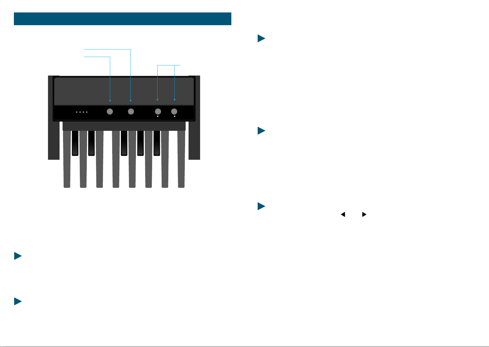
CHANNEL MIDI
OCTAVE CH. MIDI
1248
PRESET
MP 1
OCTAVE
MIDI-PEDAL MP-1
PROGRAMMIERMÖGLICHKEITEN
1.0 OKTAVLAGE
Nach dem Betätigen des Tasters "OKTAVE" läßt sich die Oktavlage des Basspedals
über die Pedaltasten einstellen:
PRESET
- C = tiefste Oktave
- Cis = eine Oktave höher u.s.w.
Nach jedem Betätigen des Tasters "OKTAVE" kann man immer nur einen OktaveWert einstellen. Ggf. erneut den "OKTAVE"-Taster drücken.
2.0 MIDI-KANAL
Nach Betätigen des Tasters "Ch. MIDI" laßen sich in gleicher Weise die MIDIKanäle einstellen:
- C = MIDI-Kanal 1
- Cis = MIDI-Kanal 2 u.s.w.
Mit dem MIDI-PEDAL haben Sie Ihr MIDI-System nicht nur um ein 13-Tasten-Pedal
erweitert, sondern Sie können z.B. auch über das Pedal Registrierungen
(Klangfarben) aus dem Expander abrufen. Dabei wurde das MIDI-Pedal so
Konstruiert, dass alle Funktionen leicht mit den Füßen durchgeführt werden
können.
DIE TECNISCHEN DATEN:
- 13 Tasten
- Frei wählbare Oktavlage
- Frei wählbarer MIDI-Kanal
- Instrument-change (Klangfarbenwechsel)
ANSCHLÜSSE:
- Netzanschluß (9 oder 12 Volt)
- MIDI OUT
60 MIDIPEDALBOARD
3.0 WEITERSCHALTEN DER KLANGFARBEN
Mit den beiden Pfeiltastern und laßen sich die MIDI-Voice-Nummern
(Klangfarben) auf dem eingestelten MIDI-Kanal vor-bzw. zurückschalten.
Die vielfältigen Möglichkeiten, die Ihnen die Keyboards bzw. das MIDI-Pedal
bieten, werden Sie erst nach einigem Ausprobieren und Experimentieren
vollständig nutzen können. Wir wünschen Ihnen also viel Freude beim
Kennenlernen Ihres neuen Instrumentes.
WARNUNG/VDE - VORSCHRIFTEN
Arbeiten unter Netzspannung können lebensgefährlich sein und sollten nur von
einem Fachmann durchgefürt werden.
Bei Sicherungstausch oder eventueller Fehlersuche im Netzspannungsbereich
(Netzeinbaustecker, Trafo, Netzschalter) grundsätzlich den Netzstecker ziehen!
61MIDIPEDALBOARD
 Loading...