


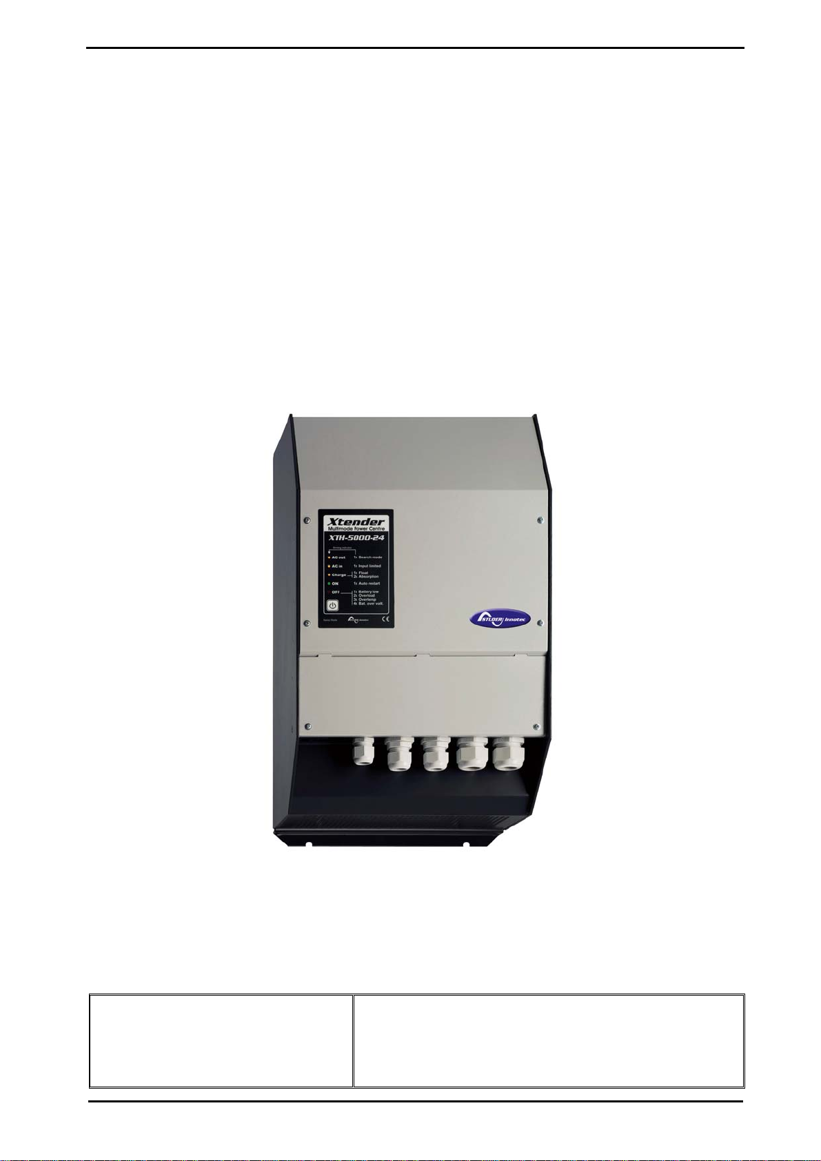
XTH 6000-48
STUDER Innotec Xtender
Installation and operating Instructions Xtender V1.3 Page 1
INSTALLATION AND OPERATING INSTRUCTIONS
Unit combining inverter, battery charger and transfer system.
Xtender
XTH 3000-12
XTH 5000-24
XTH 6000-48
XTH 8000-48
+
BTS-01 temperature sensor
STUDER Innotec
Rue des Casernes 57
CH – 1950 Sion
Tel. +41 (0)27 205 60 80
Fax. +41 (0)27 205 60 88
Customer service: info@studer-innotec.com
Sales department: sales@studer-innotec.com
Technical assistance: support@studer-innotec.com
Website: www.studer-innotec.com

STUDER Innotec Xtender
Installation and operating Instructions Xtender V1.3 Page 2
TABLE OF CONTENTS
1 INTRODUCTION................................................................................................................3
2 GENERAL INFORMATION................................................................................................3
2.1 Operating instructions...................................................................................................3
2.2 Conventions.................................................................................................................. 4
2.3 Quality and warranty .................................................................................................... 4
2.4 Warnings and notes ......................................................................................................5
3 ASSEMBLY AND INSTALLATION ...................................................................................6
3.1 Handling and moving ...................................................................................................6
3.2 Storage.......................................................................................................................... 6
3.3 Unpacking..................................................................................................................... 6
3.4 Installation site.............................................................................................................. 6
3.5 Fastening....................................................................................................................... 7
3.6 Connections.................................................................................................................. 7
4 CABLING...........................................................................................................................9
4.1 Choice of system ..........................................................................................................9
4.2 Earthing system .......................................................................................................... 10
4.3 Recommendations for dimensioning the system........................................................ 11
4.4 Wiring diagrams......................................................................................................... 12
4.5 Connecting the battery................................................................................................12
5 POWERING UP THE INSTALLATION............................................................................15
6 DESCRIPTION AND FUNCTIONING..............................................................................16
6.1 Circuit diagram........................................................................................................... 16
6.2 Description of the main functions ..............................................................................16
6.3 Multi-unit configurations............................................................................................ 22
6.4 Accessories.................................................................................................................23
7 CONTROL........................................................................................................................ 24
7.1 Main on/off control..................................................................................................... 24
7.2 Display and control parts............................................................................................24
8 MAINTENANCE OF THE INSTALLATION .....................................................................26
9 PRODUCT RECYCLING .................................................................................................26
10 EC DECLARATION OF CONFORMITY..........................................................................26
11 COMMENTS OF ANNEXES’ FIGURES..........................................................................27
12 FIGURE ELEMENT'S (DC PART)................................................................................... 29
13 FIGURE ELEMENT'S (AC PART)................................................................................... 30
14 ELEMENTS OF CONNEXION CABINET (FIG 4A) ......................................................... 31
15 CONTROL AND DISPLAY PARTS FOR THE XTENDER (FIG. 4B) ..............................32
16 TYPE PLATE ELEMENTS (FIG. 1B)...............................................................................32
17 TABLE OF STANDARD CONFIGURATIONS................................................................. 34
18 TECHNICAL DATA.......................................................................................................... 36

STUDER Innotec Xtender
Installation and operating Instructions Xtender V1.3 Page 3
1 Introduction
Congratulations! You are about to install and use a device from the Xtender range. You have chosen
a high-tech device that will play a central role in energy saving for your electrical installation. The
Xtender has been designed to work as an inverter / charger with advanced functions, which can be
used in a completely modular way and guarantee the faultless functioning of your energy system.
When the Xtender is connected to a generator or network, the latter directly supplies the consumers,
and the Xtender works like a battery charger and backup device if necessary. The powerful battery
charger has an exceptional high efficiency and power factor correction (PFC) close to 1. It
guarantees excellent battery charging in all situations. The charge profile is freely configurable
according to the type of battery used or the method of usage. The charge voltage is corrected
depending on the temperature, thanks to the optional external sensor. The power of the charger is
modulated in real time dependent according to the demand of the equipment connected at the
Xtender output and the power of the energy source (network or generator). It can even temporarily
backup the source if the consumer demand exceeds the source capacity.
The Xtender continuously monitors the source to which it is connected (network or generator) and
disconnects itself immediately if the source is missing, disturbed or does not correspond to the
quality criteria (voltage, frequency, etc.). It will then function in independent mode, thanks to the
integrated inverter. This inverter, which has an extremely robust design, benefits from STUDER
Innotec’s many years of experience and expertise in this area. It could supply any type of load
without faults, enjoying reserves of additional power that is unmatched on the market. All your
equipment will be perfectly provided with energy and protected from power outages in systems
where energy supply is unpredictable (unreliable network) or voluntarily limited or interrupted, such
as hybrid installations on remote sites or mobile installations.
The parallel and/or three-phase network operation of the Xtender offers modularity and flexibility and
enables optimum adaptation of your system to your energy requirements.
The RCC-02/03 control, display and programming centre (optional) enables optimum configuration
of the system and guarantees the operator continuous control for all important configurations in the
installation.
In order to guarantee perfect commissioning and functioning of your installation, please read this
manual carefully. It contains all the necessary information relating to the functioning of the inverters /
chargers in the Xtender series. The setting up of such a system requires special expertise and may
only be carried out by qualified personnel familiar with the applicable local regulations.
2 General information
2.1 Operating instructions
This manual is an integral part of each inverter/charger from the Xtender series.
It covers the following models and accessories:
Xtender: XTH 3000-12 – XTH 5000-24 – XTH 6000-48 – XTH 8000-48
Temperature sensor: BTS-01
For greater clarity, the device is referred to in this manual as Xtender, unit or device, when the
description of its functioning applies indiscriminately to different Xtender models.
These operating instructions serve as a guideline for the safe and efficient usage of the Xtender.
Anyone who installs or uses an Xtender can rely completely on these operating instructions, and is
bound to observe all the safety instructions and indications contained. The installation and
commissioning of the Xtender must be entrusted to a qualified professional. The installation and
usage must conform to the local safety instructions and applicable standards in the country
concerned.

STUDER Innotec Xtender
Installation and operating Instructions Xtender V1.3 Page 4
2.2 Conventions
This symbol is used to indicate the presence of a dangerous voltage that is sufficient to
constitute a risk of electric shock.
This symbol is used to indicate a risk of material damage.
This symbol is used to indicate information that is important or which serves to optimise
your system.
All values mentioned hereafter, followed by a configuration no. indicate that this value may be
modified with the help of the RCC-02/03 remote control.
In general, the default values are not mentioned and are replaced by a configuration no. in the
following format: {xxxx}. The default values for this configuration are specified in the configuration
table, p. 34.
All configuration values modified by the operator or installer must be transferred into the same table.
If a parameter not appearing in the list (advanced configurations) has been modified by an
authorised person with technical knowledge, they will indicate the number of the modified
parameter(s), the specifications of the configuration(s) and the new value set, at the end of the same
table.
All figures and letters indicated in brackets refer to items of figures in the separate manual “Appendix
to the installation and operating instructions” supplied with the device.
The figures in brackets refer to elements belonging to the Xtender.
The uppercase letters in brackets refer to AC cabling elements.
The lowercase letters in brackets refer to battery cabling elements.
2.3 Quality and warranty
During the production and assembly of the Xtender, each unit undergoes several checks and tests.
These are carried out with strict adherence to the established procedures. Each Xtender has a serial
number allowing complete follow-up on the checks, according to the particular data for each device.
For this reason it is very important never to remove the type plate (appendix I – fig. 3b) which shows
the serial number. The manufacture, assembly and tests for each Xtender are carried out in their
entirety by our factory in Sion (CH). The warranty for this equipment depends upon the strict
application of the instructions appearing in this manual.
The warranty period for the Xtender is 2 years.
2.3.1
E
XCLUSION OF WARRANTY
No warranty claims will be accepted for damage resulting from handling, usage or processing that
does not explicitly appear in this manual. Cases of damage arising from the following causes are
notably excluded from the warranty:
• Surge voltage on the battery input (for example, 48 V on the battery input of an XTH 3000-
12)
• Incorrect polarity of the battery
• The accidental ingress of liquids into the device or oxidation resulting from condensation
• Damage resulting from falls or mechanical shocks
• Modifications carried out without the explicit authorisation of Studer Innotec
• Nuts or screws that have not been tightened sufficiently during the installation or
maintenance
• Damage due to atmospheric surge voltage (lightning)
• Damage due to inappropriate transportation or packaging
• Disappearance of original marking elements
STUDER Innotec Xtender
Installation and operating Instructions Xtender V1.3 Page 5
2.3.2
E
XCLUSION OF LIABILITY
The placement, commissioning, use, maintenance and servicing of the Xtender cannot be the
subject of monitoring by Studer Innotec. For this reasons we assume no responsibility and liability for
damage, costs or losses resulting from an installation that does not conform to the instructions,
defective functioning or deficient maintenance. The use of a Studer Innotec inverter is the
responsibility of the customer in all cases.
This equipment is neither designed nor guaranteed to supply installations used for vital medical care
nor any other critical installation carrying significant potential damage risks to people or the
environment.
We assume no responsibility for the infringement of patent rights or other rights of third parties that
result from using the inverter.
Studer Innotec reserves the right to make any modifications to the product without prior notification.
2.4 Warnings and notes
2.4.1
GENERAL
This manual is an integral part of the device and must be kept available for the operator
and installer. It must remain close to the installation so that it may be consulted at any time.
The configuration table available at the end of the manual (p. 34) must be kept up to date in the
event of modification of the configurations by the operator or installer. The person in charge of
installation and commissioning must be wholly familiar with the precautionary measures and the
local applicable regulations.
When the Xtender is running, it generates voltage that can be potentially lethal. Work on or
close to the installation must only be carried out by thoroughly trained and qualified
personnel. Do not attempt to carry out ongoing maintenance of this product yourself. The
Xtender or the generator connected to it may start up automatically under certain
predetermined conditions.
When working on the electrical installation, it is important to be certain that the source of
DC voltage coming from the battery as well as the source of AC voltage coming from a
generator or network have been disconnected from the electrical installation.
Even when the Xtender has been disconnected from the supply sources (AC and DC), a
dangerous voltage may remain at the outputs. To eliminate this risk you must switch the
Xtender OFF using the ON/OFF button (1). After 10 seconds the electronics is discharged
and intervention may take place without any danger.
All elements connected to the Xtender must comply with the applicable laws and regulations.
Persons not holding written authorisation from Studer Innotec are not permitted to proceed with any
change, modification or repairs that may be required. Only original parts may be used for authorised
modifications or replacements.
This manual contains important safety information. Read the safety and working instructions
carefully before using the Xtender. Adhere to all the warnings given on the device as well as in the
manual, by following all the instructions with regard to operation and use.
The Xtender is only designed for interior use and must under no circumstances be subjected to rain,
snow or other humid or dusty conditions.
The maximum specifications of the device shown on the type plate, as at fig. 1b, must be adhered
to.
In the event of use in motorised vehicles, the Xtender must be protected from dust, splash water
and any other humid condition. It must also be protected from vibration by installing absorbent parts.
2.4.2
P
RECAUTIONS FOR USING THE BATTERIES
Lead-acid or gel batteries produce a highly explosive gas with normal use. No source of sparks or
fire should be present in the immediate vicinity of the batteries. The batteries must be kept in a well-
ventilated place and be installed in such a way as to avoid accidental short-circuits when connecting.

STUDER Innotec Xtender
Installation and operating Instructions Xtender V1.3 Page 6
Never try to charge frozen batteries.
When working with the batteries, a second person must be present in order to lend assistance in the
event of problems.
Sufficient fresh water and soap must be kept to hand to allow adequate and immediate washing of
the skin or eyes affected by accidental contact with the acid.
In the event of accidental contact of the eyes with acid, they must be washed carefully with cold
water for 15 minutes. Then immediately consult a doctor.
Battery acid can be neutralised with baking soda. A sufficient quantity of baking soda must be
available for this purpose.
Particular care is required when working close to the batteries with metal tools. Tools such as
screwdrivers, open-ended spanners, etc. may cause short-circuits. Consequently occurring sparks
may cause the battery to explode.
When working with the batteries, all metal jewellery such as rings, bracelet watches, earrings, etc.,
must be taken off. The current output by the batteries during a short-circuit is sufficiently powerful to
melt the metal and cause severe burns.
In all cases, the instructions of the battery manufacturer must be followed carefully.
3 Assembly and installation
3.1 Handling and moving
The weight of the Xtender is between 35 and 50kg depending upon the model. Use an appropriate
lifting method as well as help from a third party when installing the equipment.
3.2 Storage
The equipment must be stored in a dry environment at an ambient temperature of between
-20°C and 60°C. It stay in the location where it is to be used a minimum of 24 hours before being
set up.
3.3 Unpacking
When unpacking, check that the equipment has not been damaged during transportation and that
all accessories listed below are present. Any fault must be indicated immediately to the product
distributor or the contact given at the back of this manual.
Check the packaging and the Xtender carefully.
Standard accessories:
Installation and operating instructions, c.f. Appendix 1
Mounting plate – fig. 2a (18)
2 conduit glands for the battery cable
3.4 Installation site
The installation site for the Xtender is of particular importance and must satisfy the following criteria:
Protected from any unauthorised person.
Protected from water and dust and in a place with no condensation.
It must not be situated directly above the battery or in a cabinet with it.
No easily inflammable material should be placed directly underneath or close to the Xtender.
Ventilation apertures must always remain clear and be at least 15cm from any obstacle that may
affect the ventilation of the equipment according to fig. 2b.
In mobile applications it is important to select an installation site that ensures as low a vibration level
as possible.
STUDER Innotec Xtender
Installation and operating Instructions Xtender V1.3 Page 7
3.5 Fastening
The Xtender is a heavy unit and must be mounted to a wall designed to bear such a load.
A simple wooden panel is insufficient.
The Xtender must be installed vertically with sufficient space around it to guarantee adequate
ventilation of the device (see figs. 2a and 2b).
If the Xtender is installed in a closed cabinet this must have sufficient ventilation to guarantee an
ambient temperature that conforms to the operation of the Xtender.
Firstly, fit the mounting bracket (18) supplied with the device, using 2 Ø <6-8 mm> screws**.
Then hang the Xtender on the bracket. Fasten the unit permanently using 2 Ø <6-8 mm> screws**
on to the two notches located at the underside of the case.
**: These items are not delivered with the device.
It is imperative to ensure complete and safe fastening of the device. A device that is simply
hung may detach and cause severe damage.
In motor vehicles or when the support may be subject to strong vibrations, the Xtender must be
mounted on anti-vibration supports.
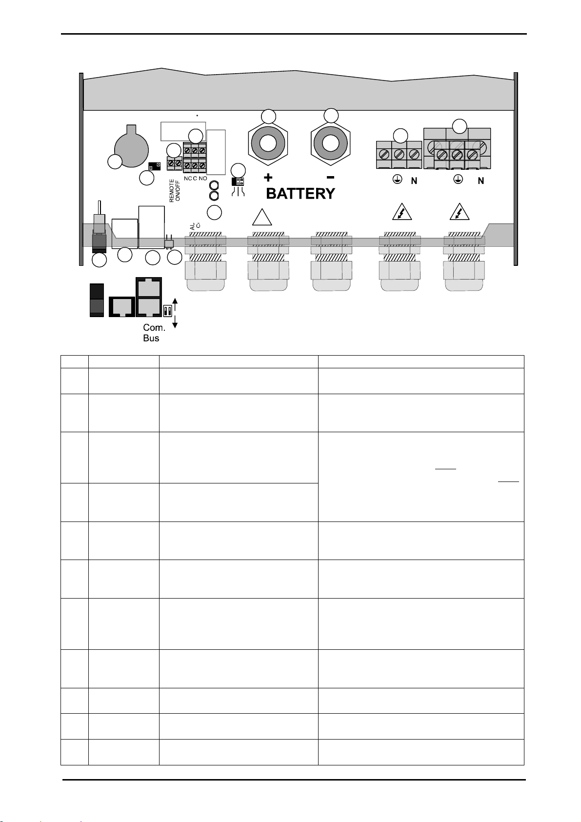
3.6 Connections
3.6.1
G
ENERAL RECOMMENDATIONS
The Xtender falls within protection class I (has a PE connection terminal). It is vital that a protective
earth is connected to the AC IN and/or AC OUT PE terminals. An additional protective earth is
located between the two fastening screws at the bottom of the unit (fig. 2b-(17)).
In all cases, the PE conductor for the equipment must at least be connected to the PE for
all equipment in protection class I upstream and downstream of the Xtender (equipotential
bonding). It is imperative that the legislation in force for the application concerned be
adhered to.
Tighten of the input (13) and output (14) terminals by means of a no. 3 screwdriver and those for the
“REMOTE ON/OFF” (7) and “AUX.CONTAC” (8) by means of a no. 1 screwdriver.
The cable sections of these terminals must conform to local regulations.
All connection cables as well as the battery cables must be mounted using cable restraints in order
to avoid any traction on the connection.
Battery cables must also be as short as possible and the section must conform with the applicable
regulations and standards. Sufficiently tighten the clamps on the “battery” inputs (fig. 4a (11) and
(12)).
3.6.2
D
EVICE CONNECTION COMPARTMENT
The unit’s connection compartment must remain permanently closed when in operation. It
is imperative to close the protection cap on the connection terminals after each intervention
in the device.
After opening, check that all
sources of AC and DC voltage (batteries) have been
disconnected or put out of service.
STUDER Innotec Xtender
Installation and operating Instructions Xtender V1.3 Page 8
Fig. 4a
A
U
X
I
L
L
A
R
Y
C
O
N
T
A
C
T
L
1
L
2
L
3
A
U
X
1
A
U
X
2
A
C
O
u
t
p
u
t
A
C
I
n
p
u
t
L
L
ON
Open
Terminated
OFF
Temp.
Sens.
1
1
2
A
B
123
2
3
5
6
7
8
9
10
11
12
4
Main
switch
13
14
!
Warning!
Check battery polarity (+/-) before connecting
A wrong connexion may damage the systen
Pos.
Denomination Description Comment
1 ON/OFF
Main switch
Main on/off switch See chapter The real time clock 7.1 - p
24.
2 Temp. Sens Connector for the battery
temperature sensor
See chapter 6.4.2 – p. 24.
Only connect the original Studer BTS-01
sensor
3 Com. Bus Double connector for
connecting peripherals such as
the RCC002/03 or other
Xtender units
4 O / T
(Open /
Terminated)
Switch for terminating the
communication bus.
See chapter 4.5.9 – p. 14.
The two termination switches (4) for the
communication bus both
remain in
position T (terminated) except when both
connectors are in use.
5 -- 3.3 V (CR-2032) lithium ion type
battery socket
Used as a permanent supply for the
internal clock. See chapter The real time
clock 6.2.11 - p 21.
6 -- Jumper for programming the
off/on switch by dry contact
See chapter 6.2.12 – p. 21 and fig. 8b
point (6) and (7). They are positioned at A-
1/2 and B-2/3 by default
7 REMOTE
ON/OFF
Connection terminals for dry
on/off remote connection.
See chapter 6.2.12– p. 21).
When the control via dry contact is not
being used, a bridge must be present
between the two terminals.
8 AUXILIARY
CONTACT
Auxiliary contact (See chapter 6.2.10– p. 21)
Take care not to exceed the admissible
loads
9 -- Activation indicators for auxiliary
contacts 1 and 2
See chapter 6.2.10– p. 21
10 L1/L2/L3 Phase selection jumpers. See chapter 6.3.1. – p.22.
Jumper default at position L1
11 +BAT Positive pole battery connection
terminals
Carefully read chapter 4.5 – p.12
Take care with the polarity of the battery

STUDER Innotec Xtender
Installation and operating Instructions Xtender V1.3 Page 9
12 -BAT Negative pole battery
connection terminals
and when tightening the clamp.
13 AC Input Connection terminals for the
alternative power supply
(generator or public network)
See chapter 4.5.7 - p. 14.
Note: It is imperative that the PE terminal
be connected.
14 AC Output Connection terminals for the
device output.
See chapter 4.5.6 - p. 14.
Note: Increased voltages may appear on
the terminals, even in the absence of
voltage at the input of the inverter.
4 Cabling
The connection of the Xtender inverter / charger is an important installation step.
It may only be carried out by qualified personnel and in accordance with the applicable local
regulations and standards. The installation must always comply with these standards.
Pay attention that connections are completely tightened and that each wire is connected at the right
place.
4.1 Choice of system
The Xtender may be used in different system types, each of which must meet the standards and
particular requirements associated with the application or site of installation. Only an appropriately
qualified installer can advise you effectively on the applicable standards with regard to the various
systems and the country concerned.
Examples of cabling are presented in appendix I of this manual, fig. 5 and following. Please carefully
read the notes associated with these examples in the tables on p. 27 and following.
4.1.1
H
YBRID TYPE STAND
-
ALONE SYSTEMS
The Xtender can be used as a primary supply system for grid-remote sites where a renewable
energy source (solar or hydraulic) is generally available and a generator is used as backup. In this
case, batteries are generally recharged by a supply source such as solar modules, wind power or
small hydropower systems. These supply sources must have their own voltage and/or current
regulation system and are connected directly to the battery. (Example, fig. 11)
When the energy supply is insufficient, a generator is used as a back-up energy source. This allows
the batteries to be recharged and direct supply to consumers via the Xtender transfer relay.
When the input voltage source is a low power generator (lower than the Xtender power) the
factory settings (adapted to grid-connection) must be modified according to the
“generator” column in the configuration table on p. 34.
4.1.2
G
RID
-
CONNECTED EMERGENCY SYSTEMS
The Xtender can be used as an emergency system, also known as an uninterruptible power supply
(UPS) – enabling a reliable supply to a site connected to an unreliable network. In the event of an
interruption to the energy supply from the public network, the Xtender, connected to a battery,
substitutes the faulty source and enables a support supply to the users connected downstream.
These will be supplied as long as the energy stored in the battery allows. The battery will quickly be
recharged at the next reconnection to the public grid.
Various application examples are described in figs. 8a – 8c in appendix I.
The use of the Xtender as a UPS must be carried out by qualified personnel who have
been checked by the responsible local authorities. The diagrams in the appendix are given
for information and as a supplement. The applicable local standards and regulations must
be adhered to.
4.1.3
I
NTEGRATED MOBILE SYSTEMS
These systems are meant to be temporarily connected to the grid and ensure the supply of the
mobile system when this is disconnected from the grid. The main applications are for boats, service
STUDER Innotec Xtender
Installation and operating Instructions Xtender V1.3 Page 10
vehicles and leisure vehicles. In these cases, two separate AC inputs are often required, one
connected to the grid and the other connected to an on-board generator. Switching between two
sources must be carried out using an automatic or manual reversing switch, conforming to the
applicable local regulations. The Xtender has a single AC input.
Various application examples are described in figs. 10a – 10b – 10c).
4.1.4
M
ULTI
-
UNIT SYSTEMS
Whatever system is selected, it is possible to realise systems composed of several units of the same
type and the same power output. Up to three Xtenders in parallel or three extenders forming a
three-phase grid or three times two with three Xtenders in parallel forming a three-phase / parallel
grid, may be thus combined.
4.2 Earthing system
The Xtender is a protection class I unit, which is intended for cabling in a grid type TT, TN-S or TNC-
S. The earthing of the neutral conductor (E) is carried out at a sole installation point, upstream of the
RCD circuit breaker (D).
The Xtender can be operated with any earthing system. In all cases it is imperative that the
protective earth be connected in compliance with the applicable standards and regulations. The
information, notes, recommendations and diagram mentioned in this manual are subject to local
installation regulations in every case. The installer is responsible for the conformity of the installation
with the applicable local standards.
4.2.1
M
OBILE INSTALLATION OR INSTALLATION CONNECTED TO THE GRID VIA PLUG CONNECTOR
When the input of the device is connected directly to the grid via a plug, the length of the cable must
not exceed 2 m and the plug must remain accessible.
In the absence of voltage at the input, the neutral and live are interrupted, thereby guaranteeing
complete isolation and protection of the cabling upstream of the Xtender.
The earthing system downstream of the Xtender is determined by the upstream earthing system
when the grid is present. In the absence of the grid, the earthing system downstream of the inverter
is in isolated mode. The safety of the installation is guaranteed by the equipotential bonding.
The connection (link) between the neutrals (C) upstream and downstream of the Xtender is
not permitted in this configuration.
This connection type guarantees the optimal continuity for supplying the Xtender loads. The first
isolation fault will not lead to an interruption in the supply.
If the installation requires the use of a permanent isolation controller this would have to be de-
activated when the TT network is present at the Xtender input.
All sockets and protection class I devices connected downstream of the Xtender must be
properly connected to the earth (earthed socket). The cabling rules above remain valid,
including fixed installations, in all cases where the Xtender input is connected to the grid via
a plug connector.
4.2.2
F
IXED INSTALLATION
The installation may be equivalent to a mobile installation (with interrupted neutral).
In a fixed installation where the neutral is connected to the earth at a single installation point
upstream of the Xtender, it is permissible to carry out a connection of the neutrals in order to
preserve an unchanged earthing system downstream, independent of the operating mode of the
Xtender. This choice has the advantage of keeping the protection devices downstream of the
Xtender. This connection can be executed according to the examples in appendix 1, or carried out
by modifying the configuration {1486}
In this case the appearance of the first fault will lead to the installation stopping or the disconnection
of the protection devices upstream and/or downstream of the Xtender.
Safety is guaranteed by the equipotential bonding and by any RCD circuit-breakers placed
downstream.
STUDER Innotec Xtender
Installation and operating Instructions Xtender V1.3 Page 11
This connection (C) is not permitted if a socket is installed upstream of the Xtender.
4.2.3
I
NSTALLATION WITH AUTOMATIC
PE-
NEUTRAL SWITCHING
In certain applications, it is desirable to keep the neutral upstream and downstream of the Xtender
separated (C) while reestablishing the earthing system (TN-S, TT or TNC-S) in the absence of
voltage at the input. This can be programmed by the configuration {1485} via the RCC-02/03
remote control. This modification must be carried out possessing technical knowledge, at the
responsibility of the installer and in conformity with the applicable regulations and standards.
This allows adherence to the requirements for an earth-neutral connection at the source.
4.3 Recommendations for dimensioning the system
4.3.1
D
IMENSIONING THE BATTERY
The battery capacity is dimensioned according to the requirements of the user – that is 5 to 10 times
its average daily consumption. The discharge depth of the battery will therefore be limited and the
service life of the battery will be extended.
On the other hand, the Xtender must have a battery capacity that is large enough to be able to take
full advantage of the performance of the equipment. The minimum capacity of the batteries
(expressed in Ah) is generally dimensioned in the following way: five times the rated power output of
the Xtender / the battery voltage. For example, the model XTH 8048 must have a battery of a
minimum capacity of 7000*5/48=730 Ah (C 10). Because of the inverter’s extreme overload capacity,
it is often recommended that this value be rounded up. An under-dimensioned battery may lead to
an accidental and undesired stopping of the Xtender in the event of high instances of use. This
stoppage will be due to a voltage that is insufficient on the battery, subject to a strong discharge
current.
The battery will be selected with regard to the greatest value resulting from the calculations set out
above.
The battery capacity determines the adjustment of the configuration {1137} “battery charge current”.
A value between 0.1 and 0.2 x C batt. [Ah] (C10) enables an optimum charge to be guaranteed.
The method proposed below is strictly indicative and in no way constitutes a guarantee of
perfect dimensioning. The installer is solely responsible for good dimensioning and
installation
4.3.2
D
IMENSIONING THE INVERTER
The inverter is dimensioned in such a way that the rated power output covers the power of all the
consumers which will be used at the same time. A dimensioning margin of 20 to 30% is
recommended to guarantee that the Xtender will work well in an ambient temperature of more than
25 °C.
4.3.3
D
IMENSIONING THE GENERATOR
The power output of the generator must be the same or more than the average daily power.
Optimally, it should be two or three times this power. Thanks to the smart boost function it is not
necessary to over-dimension the generator. Indeed, the loads those are temporarily higher than the
power of the generator will be supplied by the inverter. Ideally it should not have a power output by
phase that is less than half of the power of the Xtender(s) present at this phase.
The power available downstream of the inverter when the generator is working is the same
as the sum of the two powers.
 Loading...