


C3548
STUDER INNOTEC
COMPACT
COMPACT COMPACT
COMPACT
User manual COMPACT V2.0 E
User and installer Manual
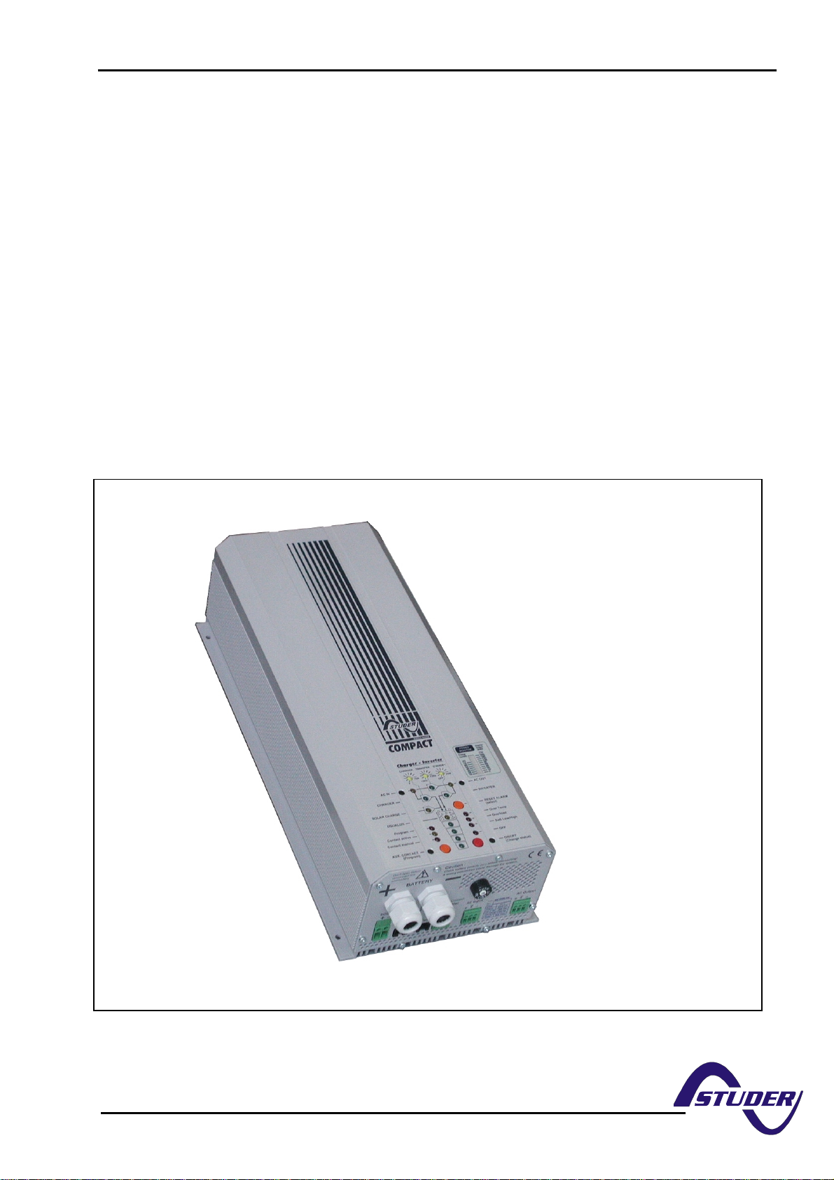
Sinewave Inverter, Battery charger
COMPACT C1312
COMPACT C1312 COMPACT C1312
COMPACT C1312
COMPACT C2324
COMPACT C2324 COMPACT C2324
COMPACT C2324
COMPACT C3548
COMPACT C3548COMPACT C3548
COMPACT C3548
Temperature sensor CT-35
Remote control RC-01
Solar charge regulator Cxxxx-S
Remote power sharing RPS-01
AC cable cover CFC-01
IP-23 top cover CxxxxIP23
STUDER INNOTEC TEL: ++41 (0)27 205 60 80
Rue des Casernes 57 FAX: ++41 (0)27 205 60 88
CH-1950 SION info@studer-inno.com

STUDER INNOTEC
COMPACT
COMPACTCOMPACT
COMPACT
User manual COMPACT V2.0 E 2
Index table
1 GENERAL INFORMATION.................................................................................................................................... 4
1.1 O
PERATING INSTRUCTIONS .................................................................................................................................... 4
1.2 Q
UALITY AND WARRANTY .................................................................................................................................... 4
1.3 W
ARRANTY DISCLAIMER....................................................................................................................................... 4
1.4 L
IABILITY DISCLAIMER.......................................................................................................................................... 4
1.5 P
RECAUTIONS ........................................................................................................................................................ 4
1.6 S
PECIAL PRECAUTIONS .......................................................................................................................................... 5
2 INTRODUCTION ..................................................................................................................................................... 6
P
RINCIPE SCHEMATIC...................................................................................................................................................... 6
2.2 D
ESCRIPTION OF MAIN FUNCTIONS ......................................................................................................................... 6
2.2.1 The Inverter .................................................................................................................................................. 6
2.2.2 The Transfer system...................................................................................................................................... 6
2.2.3 The Battery charger...................................................................................................................................... 6
2.2.4 The solar charge regulator (optional).......................................................................................................... 7
2.2.5 Remote control.............................................................................................................................................. 7
2.3 B
ATTERY CONNECTIONS ........................................................................................................................................ 7
2.3.1 Parallel Connection.......................................................................................................................................... 7
2.3.2 Series Connection ............................................................................................................................................. 7
2.3.3 Parallel- Series Connection.............................................................................................................................. 8
3 ASSEMBLY.............................................................................................................................................................. 8
3.1 P
LACE OF ASSEMBLY.............................................................................................................................................. 8
3.2 F
IXING ................................................................................................................................................................... 8
3.2.1 Compact........................................................................................................................................................ 8
3.2.2 Protection cover IP23................................................................................................................................... 8
3.3 C
ONNECTION.......................................................................................................................................................... 8
3.3.1 General instructions on connecting.............................................................................................................. 8
3.3.2 Protection cover for the terminals connections............................................................................................ 9
3.4 C
ONNECTING PLAN / FRONT SIDE........................................................................................................................... 9
3.5 C
ABLING/WIRING ................................................................................................................................................. 10
3.5.1 Pre-installation settings.............................................................................................................................. 10
3.5.2 Connection to battery ................................................................................................................................. 10
3.5.3 Connection the 230Vac-Consumer Device (AC OUTPUT) ........................................................................ 10
3.5.4 Connection the 230Vac Input (AC INPUT) ................................................................................................ 10
3.5.5 Connect the Solarmodules: SOLAR +/- (Only for solar option) ................................................................ 11
3.5.6 Connection to Auxiliary Contact ................................................................................................................ 11
3.5.7 Connection to Remote control .................................................................................................................... 11
3.5.8 Connection to Temperature Sensor (Temp.)............................................................................................... 11
4 OPERATING........................................................................................................................................................... 12
4.1 D
ISPLAY AND OPERATING CONTROL ELEMENTS 12
4.2
LIGHT EMITTING DIODES....................................................................................................................................... 12
4.3 P
USH BUTTONS..................................................................................................................................................... 13
4.4 T
URNING KNOBS.................................................................................................................................................. 13
4.5 T
HE INVERTER ..................................................................................................................................................... 14
4.5.1 Charge detection system „Standby“........................................................................................................... 14
4.5.2 Overload..................................................................................................................................................... 14
4.5.3 Overheating (Over Temp)........................................................................................................................... 14
4.5.4 Battery Condition ....................................................................................................................................... 14
4.6 T
HE BATTERY CHARGER ...................................................................................................................................... 15
4.6.1 Cycle of charge........................................................................................................................................... 15
4.6.2 Equalization charging ................................................................................................................................ 15
4.6.3 Input current repartition (Power sharing).................................................................................................. 15
4.6.4 Charging current........................................................................................................................................ 16
4.6.5 Battery Condition........................................................................................................................................ 16
4.7 T
HE TRANSFER SYSTEM ....................................................................................................................................... 16
4.7.1 Set the transfer voltage threshold............................................................................................................... 17
4.7.2 FAST (UPS)- MODE for the Transfer Switch............................................................................................. 17

STUDER INNOTEC
COMPACT
COMPACTCOMPACT
COMPACT
User manual COMPACT V2.0 E 3
4.7.3 Delayed mode of the Transfer System......................................................................................................... 17
4.8 T
HE SOLAR CHARGE REGULATOR (OPTION) ......................................................................................................... 17
4.9 T
HE MULTIFUNCTIONAL CONTACT...................................................................................................................... 17
4.10
THE REMOTE CONTROL........................................................................................................................................ 18
4.11 T
HE TEMPERATURE SENSOR................................................................................................................................. 19
5 PROGRAMMING................................................................................................................................................... 19
5.1 S
TANDARD SETTING............................................................................................................................................. 19
5.1.1 Working mode............................................................................................................................................. 19
5.1.2 Battery voltage............................................................................................................................................ 19
5.1.3 Auxiliary contact......................................................................................................................................... 19
5.2 R
ESET VALUE....................................................................................................................................................... 19
5.3 B
ATTERY VOLTAGES AND ABSORPTION TIME ....................................................................................................... 19
5.3.1 Table of voltage and timing threshold ........................................................................................................ 19
5.3.2 Set the voltage and timing threshold........................................................................................................... 20
5.4 P
ROGRAM THE AUXILIARY CONTACT ................................................................................................................... 20
5.4.1 Principle ..................................................................................................................................................... 20
5.4.2 The programming of the Auxiliary Contact is carried out in the following Steps ...................................... 20
5.4.3 Example ...................................................................................................................................................... 21
5.4.4 Manual operating of Auxiliary Contact...................................................................................................... 21
5.5 D
ISABLING SOME OF THE COMPACT FUNCTIONS................................................................................................... 21
5.5.1 Diagram of the different mode................................................................................................................... 22
6 MAINTENANCE.................................................................................................................................................... 22
7 EC COMPLIANCE ................................................................................................................................................. 22
8 TECHNICAL DATA............................................................................................................................................... 23

STUDER INNOTEC
COMPACT
COMPACTCOMPACT
COMPACT
User manual COMPACT V2.0 E 4
1 General Information
1.1 Operating instructions
This manual is a part of the delivery package of every COMPACT inverter-charger. It serves as
guidelines for safe and efficient operation of COMPACT. The instructions are only valid for use with
the following devices and options:
• COMPACT C1312
• COMPACT C2324
• COMPACT C3548
• Temperature sensor CT-35
• Remote Control RCC 01
Every person who installs a COMPACT and/or works with it must be fully familiar with the contents
of this manual and must follow exactly all the warnings and safety instructions. Installation of or any
work on the COMPACT must be carried out by a qualified and trained personnel. Installation and
application must comply with the respective local installations codes and safety regulations.
1.2 Quality and Warranty
During production and assembling, all COMPACT appliances go through many controls and tests.
Fabrication, controls and tests are carried out in accordance with firm and established procedures.
Every COMPACT has its own serial number, which helps to refer back to its original data in the
event of controls or repairs. That is why you should never remove the identification plate showing
the serial number. The production assembly and tests on all COMPACT appliances are totally
carried out in our company in Sion, Switzerland. The warranty for these appliances is valid for uses
and operating possibilities mentioned in this manual .
The warranty period for the COMPACT is 2 Years.
1.3 Warranty Disclaimer
We do not accept any responsibility for any damages occurring through use, manipulation, working
situation and handling, which are not explicitly mentioned in these operating instructions.
Following cases are not covered by the warranty:
- High voltage at INPUT (i.e. 48V at the Battery INPUT of COMPACT 1312)
Reverse polarity on Battery connections(+/- reversed)
Running liquid or oxidation through condensation in the appliance
Defects caused by force, physical or mechanical means
Changes not explicitly authorized by Studer INNOTEC
Not or only partly tightened screws and nuts after change of fuses or connecting cables
Connecting other sources of energy such as PV-Modules on the INPUT „SOLAR +/-„
Transport damage, i.e. through bad handling and /or packing.
1.4 Liability Disclaimer
Respecting this manual, servicing and method of installation, functioning, application and
maintenance of the appliance can not be controlled or supervised by Firma Studer INNOTEC.
Hence we do not accept any liability and responsibility for damages, loses and costs which result
through the use of this appliance or which result through incorrect installation, incorrect operation
or wrong application and maintenance or which by some other means maybe connected together
to these. Similarly, we do not accept any responsibility for any violation of the patents rights or
violation of any third party’s rights resulting from the use of this appliance
Studer INNOTEC reserves the right to modify the technical data or these operating instructions
without issuing any prior notice.
1.5 Precautions
This manual must be readily available for the user at all times. The user must be familiar with the
precautions and safety aspects.

STUDER INNOTEC
COMPACT
COMPACTCOMPACT
COMPACT
User manual COMPACT V2.0 E 5
During operation of COMPACT, high tensions are generated at the connections and inside of the
appliance which could be deadly fatal. Work on the appliance and on the installation should only
be carried out by qualified and trained personnel.
The whole installation connected with the COMPACT must comply with the respective valid codes
and ordinances.
Persons without the written authorization from Studer INNOTEC are strictly forbidden to carry out
any changes or repairs on the appliances. For authorized changes only original parts are to be
used.
The COMPACT may only be used when it has been installed in accordance with these instructions
and all parts have been correctly assembled and installed.
On the IN- and OUTPUT points of the COMPACT only the already selected energy sources and
consumer devices should be connected.
In order to carry out any maintenance or repair work on the COMPACT without danger, all
connections must be disconnected beforehand.
Caution: Even when a COMPACT has been disconnected from the all connections, at the
OUTPUT point there could still be deadly fatal tensions present. To remove these tensions
you must switch on the COMPACT ON with the ON/OFF switch. After one minute the
electronics are discharged and any work can now be safely carried out.
The COMPACT is only suitable for internal use and under no circumstances should it be subjected
to snow, rain, or any other wet conditions
By installations in motorized vehicles the COMPACT must be protected from water-spray and any
other wet conditions..
The COMPACT may only be connected to lead –acid or lead-gel batteries.
Caution: In normal use lead-acid and lead-gel batteries give out explosive gases. Never
smoke or allow a spark or flame in the vicinity of batteries. The batteries must always be
stored or placed in a well ventilated area, they should be placed in such a way that there is
no danger of short circuiting through carelessness. Never charge frozen batteries.
The COMPACT is not to be used or sold for life support equipment or applications.
1.6 Special Precautions
While working on batteries there should always be a second person close to you or within your
voice range, in case help is needed.
Plenty of fresh water and soap must be ready at hand so that in case of acid coming in contact with
skin , eyes and clothes, the areas in question can be thoroughly washed.
If acid enters the eyes, you must thoroughly wash the eyes with cold running water for at least 15
minutes. It is recommended that you immediately consult a medical doctor.
Baking powder neutralizes battery acid electrolyte. Always keep some at hand.
Special care must be taken when working with metal tools near or on the batteries. With tools
such as screwdrivers, spanners etc. short-circuits can result. Sparks produced by the short-circuit
can cause an explosion.
When working on batteries all personal metal items such as rings, necklaces and bracelets must
be removed. Batteries are so powerful that short-circuit with these items can melt them and thus
cause severe burns. Always follow the battery manufacturers instructions.
Under certain conditions COMPACT or a connected generator can start automatically. While
working on an electrical installation you must ensure that these appliances are disconnected
beforehand from the installation.
STUDER INNOTEC
COMPACT
COMPACTCOMPACT
COMPACT
User manual COMPACT V2.0 E 6
2 Introduction
The COMPACT is a sine wave inverter with integrated battery charger and solar charger regulator
with many additional functions, it has been developed to be used as stand-alone (independent of a
grid-system) AC provider, or as continuous / break-free current supply provider.
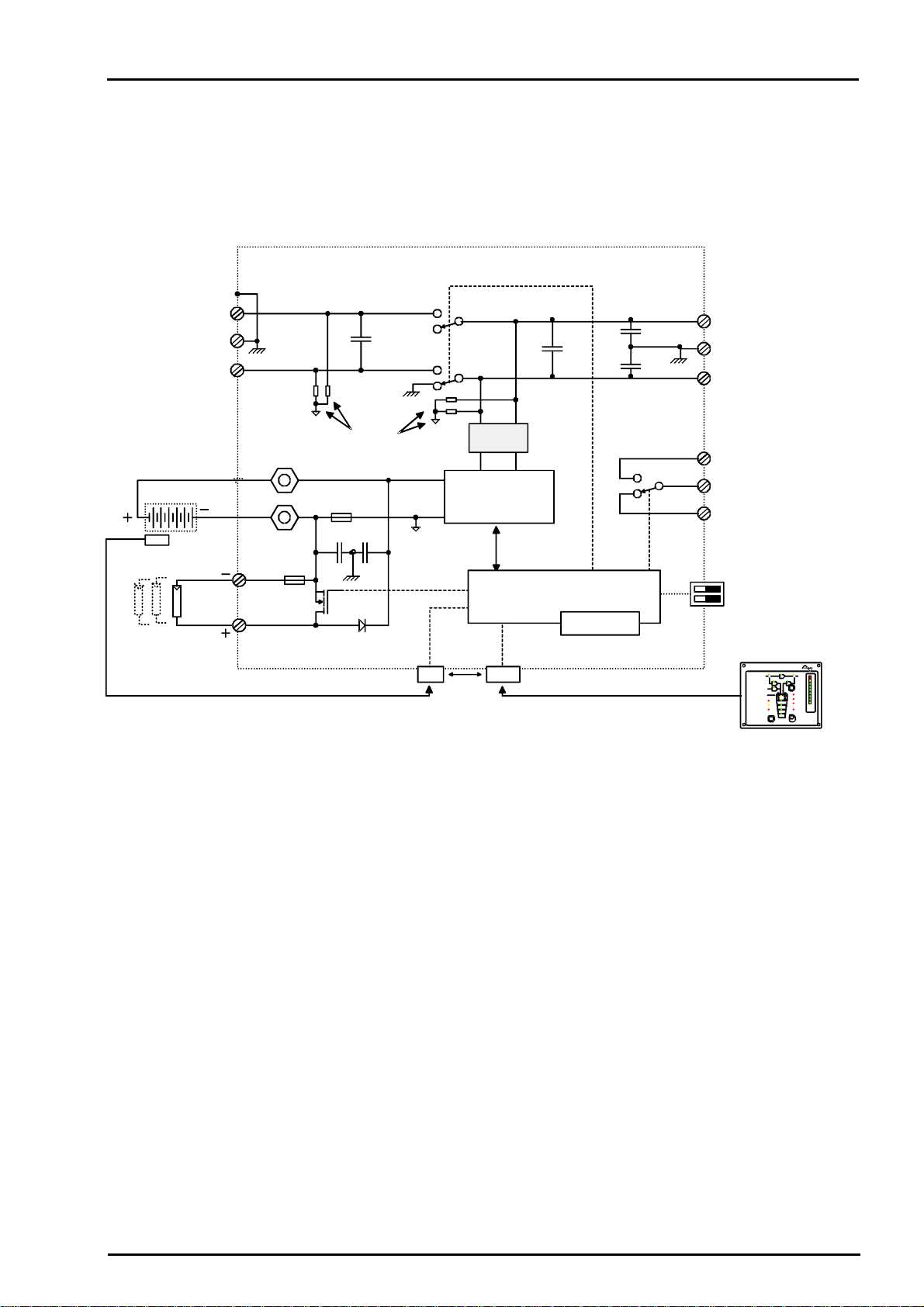
2.1 Principe schematic
2.2 Description of main functions
2.2.1 The Inverter
The sinewave-inverter built in the COMPACT generates a sinusoidal AC voltage with an
exceptionally precise voltage and stabilized frequency. In order to start large electric motors , the
user has the possibility to employ a short-start-power which is 3-times the nominal power of the
COMPACT.
The inverter is protected against overload and short-circuit. A power-stage with the latest MOS-
FET power transistors, a toroidal transformer, and a fast regulating system make-up a robust and
reliable inverter with highest efficiency. An 1-20 Watt adjustable charge detection system serves
to provide the smallest energy consumption and ensures a long life for the battery.
2.2.2 The Transfer system
COMPACT can be connected to an AC source. For example a stand-by emergency generator or
the AC network. With the transfer system, on one side you have an alternating voltage at the
output for use by the connected consumer devices. On the other side the batteries are charged.
The distribution of energy between the consumer devices and battery charger is automatic.
2.2.3 The Battery charger
The built-in battery charger is so arranged that it can charge the batteries quick very completely. A
microprocessor controlled, 3 to 4 Step charging process ensures the optimum charging of the
batteries. The desired charging current can be set continuously from 0 – 55A (C3548: 0 - 50A).
The battery charger is meant for the lead-acid and lead-gel batteries. Thanks to the floating charge
system the batteries can remain continuously connected.
6p 8p
RJ11
OFF
AC OUT
Over Temp.
Overload
AC IN
SOLAR CHARGE
Contact manual
Contact active
Program
COMPACT
AUXILIARY CONTACT ON/OFF
INVERTER - CHARGER
(Select)
RCC-01
INVERTERCHARGER
(Program) (Change status)
Battery
Low/High
RESET
A
LARM
10
20
30
40
50
60
70
TRANSFER
Ch
arg
er
Inv
ert
er
5
10
20
40
60
80
100
130
160
A %
EQUALIZE
SOLAR
AUX. CONT
.
L
PE
N
L
PE
N
Remote control
BATTERY
CT35
100nF
1uF
10nF
10nF
1uF
150A
1uF
4x2,7M
Ω
Remote control
Temp.
Max. 6m
Max. 40m
A
C OUT
Filter
Microprocessor,
Control, Adjustment
Display
Inverter
Charger
Remote control
Solarmodule
Temp. Sensor
Battery
Input
230Vac
Output
230Vac
AC IN
STUDER INNOTEC
COMPACT
COMPACTCOMPACT
COMPACT
User manual COMPACT V2.0 E 7
2.2.4 The solar charge regulator (optional)
With the built-in solar charge regulator, the COMPACT is a complete solar-power-center. In a solar
installation this regulator ensures that the batteries are charged correctly. With the COMPACT,
batteries can be charged with a generator and with the solar modules at the same time. The
charging of batteries with both energy sources is carried out fully automatically.
2.2.5 Remote control
As an option, a remote control can be connected to COMPACT. All operating elements and
displays with the exception of the level adjustment are available on the remote control. The remote
control is furnished with a 20m long cable. This cable can go to 40m long. On the remote control
output power and charging current are also shown.
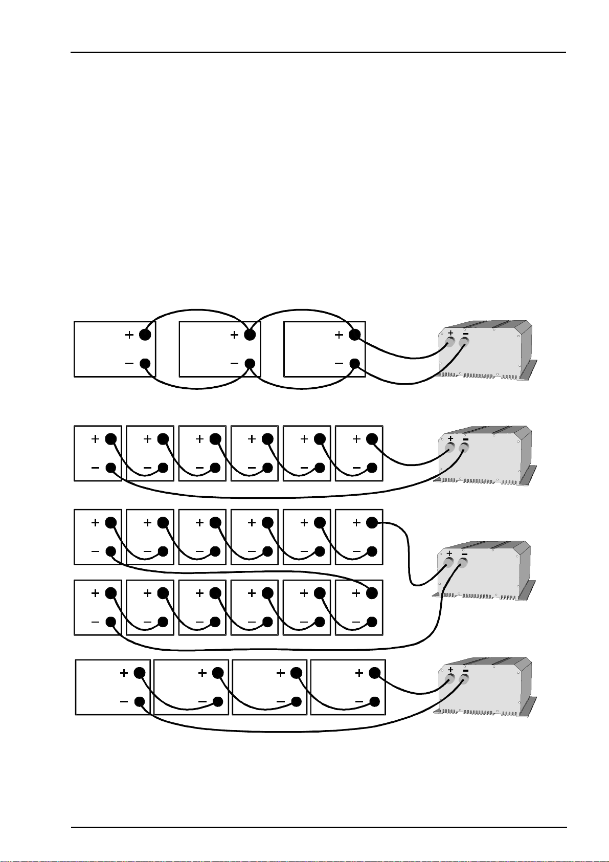
2.3 Battery connections
Lead-acid batteries are normally available in blocks of 2V, 6V or 12V . In most cases, to generate
the necessary operating voltage and the capacity of the batteries for the COMPACT many
batteries have to be connected together in parallel and or in series. Following three examples are
shown:
2.3.1 Parallel Connection:
2.3.2 Series Connection:
12V 12V 12V
12V
2V 2V 2V 2V 2V 2V
12V
48V
12V 12V 12V 12V
2V 2V 2V 2V 2V 2V
24V
2V 2V 2V 2V 2V 2V
 Loading...