


HPC 2800-12
STUDER INNOTEC TEL : ++41 (0)27 205 60 80
Rue des Casernes 57 FAX : ++41 (0)27 205 60 88
CH – 1950 Sion E-MAIL : info@studer-innotec.com
User’s and installer’s Manual
Sine wave Inverter, Battery charger, Transfersystem
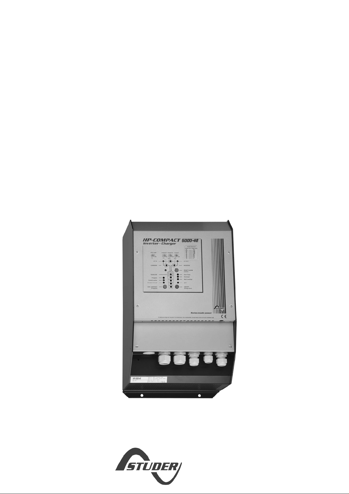
HP-COMPACT - HPC 2800-12
HP-COMPACT - HPC 4400-24
HP-COMPACT - HPC 6000-48
HP-COMPACT - HPC 8000-48
Remote control RCC-01
Remote - Power sharing RPS-01
Temperature sensor CT-35

STUDER INNOTEC HP-COMPACT
HP-COMPACT V5.4 2/80
English description..................................................................................................................5
1 General Information.........................................................................................5
1.1 Operating instructions........................................................................................ 5
1.2 Quality and Warranty.........................................................................................5
1.3 Warranty Disclaimer...........................................................................................5
1.4 Liability Disclaimer..............................................................................................6
1.5 Warning................................................................................................................ 6
1.6 Special precautions............................................................................................ 6
2 Introduction........................................................................................................7
2.1 Principle schematic ............................................................................................ 7
2.2 Description of the main functions.....................................................................8
2.3 Battery connecting..............................................................................................9
3 Mounting and installing................................................................................ 10
3.1 Installation place...............................................................................................10
3.2 Fixing.................................................................................................................. 10
3.3 Connections....................................................................................................... 10
3.4 Connection Plan................................................................................................10
3.5 Cabling...............................................................................................................11
3.6 Pre-installation settings....................................................................................11
4 Control............................................................................................................... 14
4.1 Display and control parameters......................................................................14
4.2 Light Emitting Diodes (LED)............................................................................15
4.3 Push buttons......................................................................................................16
4.4 Turning Knobs................................................................................................... 16
4.5 The Inverter....................................................................................................... 16
4.6 The battery charger.......................................................................................... 18
4.7 The Transfer system........................................................................................ 20
4.8 The Multifunctional Contact ............................................................................ 21
4.9 The Remote Control RCC-01.........................................................................22
4.10 The Temperature sensor CT-35..................................................................... 22
4.11 Remote control for „Power Sharing“ RPS-01...............................................23
5 Programming...................................................................................................23
5.1 Standard setting................................................................................................23
5.2 Reset value (default settings).........................................................................24
5.3 Battery voltages and absorption time............................................................ 24
5.4 Auxiliary contact................................................................................................25
5.5 Disabling some of the HP-COMPACT functions .........................................27
6 Installation Maintenance ..............................................................................27
7 Declaration of CE Compliance....................................................................27
8 Technical Data................................................................................................. 28

STUDER INNOTEC HP-COMPACT
HP-COMPACT V5.4 5/80
English description
1 General Information
1.1 Operating instructions
This manual is part of the delivery package of every HP-COMPACT inverter-charger.
It serves as guidelines for safe and efficient operation of HP-COMPACT. The
instructions are only valid for use with the following devices and options:
− HP-COMPACT : HPC 2800-12 – HPC 4400-24 – HPC 6000-48– HPC 8000-48
− Temperature sensor : CT-35
− Remote Control : RCC 01
− Remote power sharing : RPS-01
Every person who installs a HP-COMPACT and/or works with it must be fully familiar
with the content of this manual and must follow exactly all the warning and safety
instructions. Installation of or any work on the HP-COMPACT must be carried out by
a skilled and trained personnel. Installation and application must comply with the
respective local installations codes and safety regulations.
1.2 Quality and Warranty
During production and assembling, all HP-COMPACT appliances go through many
controls and tests. Production, controls and tests are carried out in accordance with
firm and established procedures. Every HP-COMPACT has its own serial number,
which helps to refer back to its original data in the event of controls or repairs. That is
why you should never remove the identification plate showing the serial number. The
production assembly and tests on all HP-COMPACT appliances are totally carried
out in our company in Sion, Switzerland. The warranty for these appliances is valid
for uses and operating possibilities mentioned in this manual.
The warranty period for the HP-COMPACT is 2 years.
1.3 Warranty Disclaimer
We do not accept any liability for any damages occurring through use, manipulation,
working situation and handling, which are not explicitly mentioned in these operating
instructions.
Following cases are not covered by the warranty:
− High voltage at INPUT (i.e. 48V at the Battery INPUT of HP-COMPACT 2800-
12)
− Reverse polarity on Battery connections (+/- reversed)
− Running liquid or oxidation through condensation in the appliance
− Defects caused by force, physical or mechanical means
− Changes not explicitly authorized by STUDER INNOTEC
− Not or only partly tightened screws and nuts after change of fuses or cables
connecting
− Transport damage, i.e. through bad handling and /or packing
− Damage from atmospheric over voltage (lightning)

STUDER INNOTEC HP-COMPACT
HP-COMPACT V5.4 6/80
1.4 Liability Disclaimer
Respecting this manual, servicing and method of installation, functioning, application
and maintenance of the appliance can not be controlled or supervised by STUDER
INNOTEC. Hence we do not accept any liability and responsibility for damages,
losses and costs which result through the use of this appliance or which result
through incorrect installation, incorrect operation or wrong application and
maintenance, or which by some other means maybe connected to each other.
The use of STUDER INNOTEC’s inverters does exclusively involve the user’s
liability.
This device is not designed for applications involving health care and medical
treatments where the patient life is concerned and where any mishap may be lethal.
Similarly, we do not accept any liability for any violation of the patents rights or
violation of any third party’s rights resulting from the use of this appliance
STUDER INNOTEC reserves the right to modify the technical data or these operating
instructions without any prior notice.
1.5 Warning
This manual must be readily available for the user at any time. The user must be
familiar with the precautions and safety aspects in the country of installation.
During operation of HP-COMPACT, high voltages are generated at the connections
and inside of the appliance which could be lethal. Work on the appliance and on the
installation should only be carried out by skilled and trained people.
The whole installation connected with the HP-COMPACT must comply with the rules
and codes in force.
People without the written authorization from STUDER INNOTEC are strictly
forbidden to carry out any change or repair on the appliances. For authorized
changes only original parts are to be used.
The HP-COMPACT may only be used when it has been installed in accordance with
these instructions and all parts have been correctly assembled and installed.
The HP-COMPACT may only be connected to lead-acid or lead-gel batteries.
Caution: Even when a HP-COMPACT has been disconnected from all
connections, at the OUTPUT point there could still be deadly voltages present.
To remove these voltages you must switch on the HP-COMPACT ON with the
ON/OFF switch. After one minute the electronics are discharged and any work
can now be safely carried out.
The HP-COMPACT is only suitable for internal use and under no circumstances
should it be subjected to snow, rain, or any other wet conditions.
By installations in motorized vehicles the HP-COMPACT must be protected from
water-spray and any other wet conditions.
Caution: In normal use lead-acid and lead-gel batteries give out explosive
gases. Never smoke or allow a spark or flame in the vicinity of batteries. The
batteries must always be stored or placed in a well ventilated room, they
should be placed in such a way that there is no danger of short-circuit through
carelessness. Never charge frozen batteries.
1.6 Special precautions
− While working on batteries there should always be a second person close to you
or within your voice range, in case help is needed.
STUDER INNOTEC HP-COMPACT
HP-COMPACT V5.4 7/80
− Plenty of fresh water and soap must be ready at hand so that in case of acid
coming in contact with skin, eyes and clothes, the areas in question can be
thoroughly washed.
− If acid enters the eyes, you must thoroughly wash them with cold running water
for at least 15 minutes. It is recommended that you immediately consult a
medical doctor.
− Baking powder neutralizes battery acid electrolyte. Always keep some at hand.
− Special care must be taken when working with metal tools near or on the
batteries. With tools such as screwdrivers, spanners etc. short-circuits can
result. Sparks produced by the short circuit can cause an explosion.
− When working on batteries all personal metal items such as rings, necklaces
and bracelets must be removed. Batteries are so powerful that short-circuit with
these items can melt them and thus cause severe burns. Always follow the
battery manufacturer instructions.
− Under certain conditions HP-COMPACT or a connected generator can start
automatically. While working on an electrical installation you must ensure that
these appliances are disconnected beforehand from the installation.
2 Introduction
The HP-COMPACT is a sine wave inverter with integrated battery charger with many
additional functions, it has been developed to be used as stand-alone (no grid-
feeding) AC provider, or as continuous / break-free current supply provider (UPS).
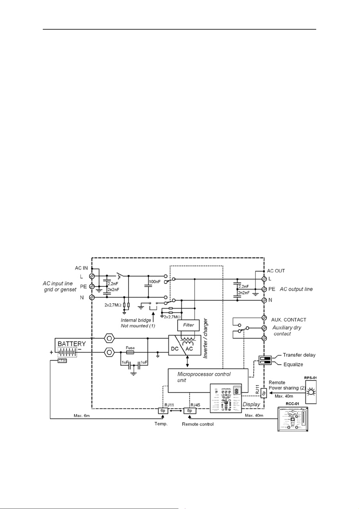
2.1 Principle schematic
Notes:
(1) The neutral of the appliance is not connected to the earth whatever the
function mode is. If requested and according to the local regulation, an automatic

STUDER INNOTEC HP-COMPACT
HP-COMPACT V5.4 8/80
connection between Neutral and earth in inverter mode only may be done by
installing a bridge internally to the unit. Please contact your installer regarding this
point.
(2) Remote control for remote adjustment of the input limit. (see chap. 4.6.3)
2.2 Description of the main functions
2.2.1 The inverter
The sine wave inverter HP-COMPACT generates a sinusoidal AC voltage with an
exceptionally precise voltage and stabilized frequency. In order to start large electric
motors, the user has the possibility to use a short surge power which is 3 times the
nominal power of the HP-COMPACT.
The inverter is protected against overload and short circuit. A power stage with the
latest MOS-FET power transistors, a toroidal transformer, and a fast regulating
system makes a robust and reliable inverter with the highest efficiency. A 1-20 Watt
adjustable charge detection system allows the smallest energy consumption and
ensures a long life for the battery.
2.2.2 The transfer system
HP-COMPACT can be connected to an AC source. For example a stand-by
emergency generator or the AC network. With the transfer system, on one side you
have an alternating voltage at the output for the use of consumer appliances. On the
other side the battery park is being charged. The distribution of energy between the
consumer appliances and battery charger is automatic.
2.2.3 The battery charger
The built-in battery charger is so designed that it can charge the battery quickly and
fully. A microprocessor controlled, Step charging process, ensures the optimal
charging of the battery. The desired charging current can be set continuously from 0
to 70/90/100/110 A, as per the model. The setting is made accordingly to the battery
capacity and power available.
The battery charger is designed for lead-acid and lead-gel batteries. Thanks to the
floating charge system the batteries can remain continuously connected.
2.2.4 Remote control
As an option, a remote control RCC-01 can be connected to HP-COMPACT. All
operating features and displays, save the adjustment levels (22/23/24/26), are
available on the re-mote control. It is supplied with a 20m long cable. This cable can
be up to 40m long. On the remote control, output power and charging current are
also displayed.
2.2.5 Remote control for Power Sharing
This remote control RPS-01 can be connected to the HP-COMPACT in the gland for
the temperature sensor. The maximum current available from the energy source can
be adjusted by the turning button.

STUDER INNOTEC HP-COMPACT
HP-COMPACT V5.4 9/80
2.3 Battery connecting
Lead-acid batteries are normally available in blocks of 2V, 6V or 12V. In most cases,
to generate the necessary operating voltage and the capacity of the batteries for the
HP-COMPACT many batteries have to be connected together in parallel and or in
series. Here are 3 examples of connection:
2.3.1 Connection in parallel
2.3.2 Serial connection
2.3.3 Serial and parallel connection

STUDER INNOTEC HP-COMPACT
HP-COMPACT V5.4 10/80
3 Mounting and installing
3.1 Installation place
The location of the HP-COMPACT must be driven by the following criteria:
− Protection from unauthorized handling
− Dry dust free room, no condensation
− Never install directly over the battery and never in a cabinet together with the
batteries
− Keep ventilation holes free
− In mobile installations it is important to keep the vibrations down as low as
possible
3.2 Fixing
Basically the HP-COMPACT can be installed in any desired location but only
vertically. First of all the plate supplied along with the HP-COMPACT must be
screwed firmly (due to the weight of the device) on the wall. Then the HP-COMPACT
is hooked on the plate and screwed underneath.
Cautious: the fixing must be fully made otherwise the HP-COMPACT may fall
and cause important damages.
In motor vehicles HP-COMPACT must be fixed on vibrations reducing elements. The
HP-COMPACT must not be fixed on a combustible base, as the back of the casing
can get hot and reach up to 60 degrees Celsius.
3.3 Connections
3.3.1 General instructions on connecting
− The cable connection on the terminals AC INPUT and AC OUTPUT must be
carried out with a screwdriver Nr.3 and the connection of the AUX RELAY
terminal with a screwdriver Nr.2.
− The conductor cross section on the terminals AC INPUT / AC OUTPUT / must
comply with the local rules.
− All connecting cables and also the battery cables must be fixed with strain relief
clamps.
− The fuses supplied with the HPC 4400-24, 6000-48 and 8000-48 have to be
installed (see description in 3.4). The cable cross section for the HP 2800-12,
4400-24, 6000-48 and 8000-48 is resp. 95, 70, 50 and 70 mm2 and their length
must be as short as possible (max. 2m).
− The fuse supplied with t he product (save for HPC 2800-12) does not protect the
battery cables.
− To protect the battery cables, a fuse corresponding to the conductor cross
section must be fixed directly on to the battery.
− All cables must be tightly screwed in place. For safety, a yearly control is
recommended. In mobile installations controls must be carried out more often.
− Connecting must be done by qualified people. Material such as cable,
connectors and distribution boxes, fuses etc. used in the installation must
comply with the respective valid low-voltage installation rules and regulations in
force.
3.3.2 Protection cover of the terminals connections
The protection cover must to be closed after any service on the appliance.
3.4 Connection Plan
 Loading...