

Page 1

Owner’s manual
Bedienerhandbuch
Mode d'emploi
SBM-01
high precision battery monitor
Studer Innotec
Rue des Casernes 57
CH - 1950 Sion - Switzerland
Tel : +41 27 205 60 80
Fax : +41 27 205 60 88
www.studer-inno.com
SBM-01 V1.0
Page 2

SBM-01 high precision battery monitor
Owner’s manual
Bedienerhandbuch
Mode d'emploi
SBM-01
high precision battery monitor
Studer Innotec
Rue des Casernes 57
CH - 1950 Sion - Switzerland
Tel : +41 27 205 60 80
Fax : +41 27 205 60 88
www.studer-inno.com
1
Page 3

SBM-01 high precision battery monitor
English Page 3
Deutsch Seite 23
Francais Page 45
2
Page 4

SBM-01 high precision battery monitor
TABLE OF CONTENTS
1. BATTERY MONITOR BASICS . . . . . . . . . . . . . . . 4
1.1 Why should I monitor my battery? . . . . . . . . . . . 4
1.2 How does the SBM-01 work? . . . . . . . . . . . . . 4
2. SETTING UP THE SBM-01 . . . . . . . . . . . . . . . . . 5
2.1 Charge Efficiency Factor (CEF) . . . . . . . . . . . . 5
2.2 Peukert’s exponent . . . . . . . . . . . . . . . . . 6
2.3 Charged-parameters . . . . . . . . . . . . . . . . 7
2.4 Synchronizing the SBM-01 . . . . . . . . . . . . . . 8
2.5 Function overview . . . . . . . . . . . . . . . . . . 8
3. GENERAL OPERATION . . . . . . . . . . . . . . . . . . 14
4. ADVANCED FEATURES . . . . . . . . . . . . . . . . . 16
4.1 History data . . . . . . . . . . . . . . . . . . . . 16
4.2 Reset menu . . . . . . . . . . . . . . . . . . . . 16
4.3 PC-link . . . . . . . . . . . . . . . . . . . . . . 17
4.4 Super-lock . . . . . . . . . . . . . . . . . . . . . 17
5. TROUBLESHOOTING GUIDELINE . . . . . . . . . . . . . 18
5.1 Warranty. . . . . . . . . . . . . . . . . . . . . . 19
6. TECHNICAL DATA . . . . . . . . . . . . . . . . . . . . 20
6.1 Declaration of conformity . . . . . . . . . . . . . . . 22
3
Page 5

SBM-01 high precision battery monitor
1. BATTERY MONITOR BASICS
1.1 Why should I monitor my battery?
Batteries are used in a wide variety of applications, mostly to store
energy for later use. But how do you know how much energy is stored in
your battery? No one can tell you that by just looking at it. Battery
technology is often underestimated, but some basic battery knowledge
and good monitoring is essential if you want a maximum life time of your
expensive batteries. The life time of batteries is dependent on many
aspects. Battery life time reduces by under-charging, over-charging, too
deep discharging, too fast discharging and too high ambient
temperature. By monitoring your battery with an advanced battery
monitor like the SBM-01, important feedback is given to the user so that
measures can be taken when necessary. This way, by extending battery
life time, the SBM-01 will quickly merit itself back.
1.2 How does the SBM-01 work?
The capacity of a battery is rated in Amphours (Ah). For example, a
battery that can deliver a current of 5Amps for a period of 20hours is
rated at 100Ah (5 * 20 = 100). The SBM-01 continuously measures the
present current flow in or out of the battery so it can calculate the amount
of energy removed from or added to the battery. But since battery age,
discharge current and temperature all influence the battery’s capacity,
you cannot rely on an Amp-hours reading. When the same 100Ah
battery is discharged completely in two hours, it will give you only 56Ah.
As you can see the battery’s capacity is almost halved. This
phenomenon is called Peukert efficiency (see also chapter 2.2). When
the temperature of the battery is low too, its capacity is decreased even
more. This is why simple Amphour counters or Voltmeters are not able to
give you an accurate state-of-charge indication.
The SBM-01 can display both Amphours removed (not compensated)
and actual state-of-charge (compensated by Peukert efficiency, charge
efficiency and temperature). Reading state-of-charge is the best way to
read your battery. This parameter is given in percent, where 100.0%
represents a fully charged battery and 0.0% a completely flat battery.
You can compare this with a fuel-gauge in a car.
4
Page 6

SBM-01 high precision battery monitor
The SBM-01 also makes an estimation of the time the battery can
support the present load (time-to-go readout). This is actually the time
left till the battery needs to be charged again. If the battery load is
fluctuating heavily it’s best not to rely on this reading too much since it is
a momentary readout and must be used as a guide only. We always
encourage the use of the state-of-charge readout for accurate battery
monitoring.
Besides the main function of the SBM-01, displaying the actual battery
status, this monitor offers a lot of other features too. The readout of
actual battery voltage, current and temperature (with optional
temperature sensor), the ability to store history data, the PC
computerlink and the Super-lock function are just a few features of the
SBM-01. These features are more specifically explained in the
corresponding chapters of this manual.
2. SETTING UP THE SBM-01
Before proceeding with this chapter, please make sure your SBM-01
is completely installed in accordance with the enclosed installation
guide.
When your SBM-01 is installed it is time to adjust the battery monitor to
your battery system. But before discussing the functions in the setup
menu, four important items are explained first in the next chapters. It is
important that users of the SBM-01 are having some insight in these four
items to become more familiar with battery monitoring. The actual setup
menu functions are explained in chapter 2.5 ‘Function overview’.
2.1 Charge Efficiency Factor (CEF)
Not all energy transferred into the battery during battery charging, is also
available during discharging of the battery. The charge efficiency of a
brand new battery is approximately 90%, meaning that 10Ah must be
transferred to the battery to get 9Ah actually stored in
the battery. This
efficiency figure is called Charge-Efficiency-Factor (CEF) and will
decrease with battery age. The SBM-01 can automatically calculate the
CEF of the battery.
5
Page 7

−
−
SBM-01 high precision battery monitor
2.2 Peukert’s exponent
As mentioned earlier in chapter 1.2 the Peukert efficiency describes that
if you discharge a battery faster than the 20hr rating, it’s Amphour size
decreases. The amount of battery size decrease is called ‘Peukert
exponent’ and can be adjusted from 1.00 up to 1.50 in Function F10. The
higher the Peukert exponent the faster the battery size shrinks with
increasing discharge rate. An ideal (theoretical) battery has a Peukert
Exponent of 1.00 and doesn’t care how big the discharge current is. Of
course these batteries do not exist, and an F10 setting of 1.00 is only
implemented to bypass Peukert compensation in the SBM-01.
The default setting for the Peukert exponent is 1.25, and is an
acceptable average value for most lead acid type of batteries. However
for precise battery monitoring, entering the right Peukert exponent is
essential. If the Peukert exponent is not provided with your battery, you
can calculate it by using other specifications which must be provided with
your battery. The Peukert equation is stated below :
1log2log
Cp = I
n
⋅t where Peukert exponent ‘n’ =
2log1log
IItt−
The battery specifications needed for calculation of the Peukert
exponent, are the rated battery capacity (usually the 20hr discharge
rate
(1)
) and for example a 5hr discharge rate
(2)
. See the calculation
example below to define the Peukert exponent using these two
specifications :
5hr rating, C5 = 75Ah
→ t1 = 5hr
→ I1 = 75Ah/5hr = 15A
20hr rating, C20 = 100Ah (rated capacity)
→ t2 = 20hr
→ I2 = 100Ah/20hr = 5A
5log20log
Peukert exponent n =
−
= 1,26
5log15log
6
Page 8

−
(1)
Please note that the rated battery capacity can also be defined as
SBM-01 high precision battery monitor
the 10hr or even 5hr discharge rate.
(2)
The 5hr discharge rate in this example is just arbitrary. Make sure
that besides the C20 rating (low discharge current) you choose a
second rating with a substantially higher discharge current.
When no ratings are given at all, you can measure your battery using a
‘constant load bank’. This way a second rating can be obtained, besides
the 20hr rating which represents the rated battery capacity in most
cases
(1)
. This second rating can be defined by discharging a fully
charged battery with a constant current, until the battery reaches 1.75V
per cell (is 10.5V for a 12V battery or 21V for a 24V battery). a
calculation example is shown below :
A 200Ah battery is discharged with a constant current of 20A and after
8.5 hours 1.75V/cell is reached.
So, → t1 = 8.5hr
→ I1 = 20A
20hr rating, C20 = 200Ah
→ t2 = 20hr
→ I2 = 200Ah/20hr = 10A
5.8log20log
Peukert exponent n =
−
= 1,23
10log20log
2.3 Charged-parameters
Based on increasing charge voltage and decreasing charge current, a
decision can be made whether the battery is fully charged or not. When
the battery voltage is above a certain level during a predefined time while
the charge current is below a certain level during the same time, the
battery can be considered as fully charged. These voltage and current
levels as well as the predefined time are called ‘charged-parameters’. In
general for a 12V lead acid battery, the voltage-charged-parameter is
13.2V and the current-charged-parameter is 2.0% of the total battery
capacity (e.g. 4A with a 200Ah battery). A charged-parameter-time of 4
minutes is sufficient for most battery systems. Please note that these
7
Page 9

SBM-01 high precision battery monitor
parameters are very important for correct operation of your SBM-01, and
must be set appropriately in the corresponding Functions.
2.4 Synchronizing the SBM-01
For a reliable readout of the state of charge of the battery, the battery
monitor has to be synchronized regularly with battery and charger. This
is accomplished by fully charging the battery. When the charger is
operating in the ‘float’ stage, the charger considers the battery full. At this
moment the SBM-01 must reckon the battery as full too, so that the
Amphour counting can be reset to zero and the state-of-charge reading
set to 100.0%. By precisely adjusting the charged-parameters in the
SBM-01, the battery monitor can automatically synchronize with the
charger when the ‘float’ stage is reached. The range of the chargedparameters is wide enough to adjust the SBM-01 to most battery
charging methods.
When the SBM-01 cannot be adjusted to the charging algorithm of the
installed charger, the user can always synchronize the battery monitor
manually when the battery is fully charged. This is realized by pressing
both < and > selection keys simultaneously for three seconds. By
manually synchronizing the battery monitor, the CEF will not be
calculated automatically. When the supply voltage of the SBM-01 has
been interrupted, the battery monitor must always be synchronized
in order to operate correctly.
Please note that regularly (at least once per month) fully charging your
battery not only keeps it in sync with the SBM-01, but also prevent
substantial capacity loss of your battery limiting it’s life time.
2.5 Function overview
The SBM-01 factory settings are suitable for an average 12V lead acid
battery system of 200Ah. So in most cases when monitoring a 12V
system, the only Function which possibly needs to be changed is the
battery capacity (F01). When using other types of batteries please
ensure that all the relevant specifications are known to properly setup the
SBM-01 Functions.
Users can fully adjust their SBM-01 with the help of twenty different
settings, called ‘Functions’. Before setting up the SBM-01, the user has
8
Page 10

SBM-01 high precision battery monitor
to activate the setup-mode first. The setup-mode can be activated by
pressing the SETUP key for three
seconds. The display will blink to
indicate that the setup-mode is active. By repeatedly pressing the
SETUP key the desired Function can be selected. The selected Function
is represented as Fxx where xx indicates the Function number. The <
and > keys can be used to alter the value of the selected Function. By
pressing the SETUP key again, the next Function will be selected. To
save the changed settings to the SBM-01 memory, the SETUP key must
be pressed for three seconds until the display stops flashing and the
battery monitor jumps back normal operating mode again. If the SBM-01
operates in the setup-mode and not a single key is pressed for 90
seconds, the monitor will jump back to normal operating mode
automatically, without saving eventually altered settings.
The table below gives an overview of all SBM-01 Functions including a
short description. It is recommended not to change the Functions F04,
F05, F06, F09, F10, F11, F12, F13, F14, F15, F16, F17, F18 and F20
when in doubt. For most battery systems, only adjusting the values of
Functions F01, F02, F03, F07 and F08 should be sufficient.
F01 : Battery capacity in Amphours (Ah). This must be the capacity
at a 20h discharge rate and 20 °C (or 68°F).
Default : 200Ah
Range : 20 – 2000Ah
Stepsize : 1Ah
F02 : Voltage-charged-parameter. The battery voltage must be
above this voltage level to consider the battery as fully
charged. Make sure the voltage-charged-parameter is always
slightly below the voltage at which the charger finishes
charging the battery (usually 0.1V or 0.2V below the ‘float’
stage voltage of the charger).
Default : 13.2V
Range : 8.0 – 33.0V
Stepsize : 0.1V
F03 : Current-charged-parameter. When the charge current value is
below this percentage of the battery capacity (see F01), the
battery can be considered as fully charged. Make sure the
current-charged-parameter is always greater than the
minimum current at which the charger maintains the battery,
9
Page 11

SBM-01 high precision battery monitor
or stops charging.
Default : 2.0%
Range : 0.5 – 10.0%
Stepsize : 0.5%
F04 : Charged-parameter-time. This is the time the charged-
parameters (as described in F02 and F03) must be met, in
order to consider the battery as fully charged.
Default : 4 minutes
Range : 1 – 4 minutes
Stepsize : 1 minutes
F05 : Low-battery alarm ON (discharge floor). When the state-of-
charge percentage has fallen below this value, the alarm relay
will be activated and the CHARGE BATTERY indication will
flash on the display to indicate the battery must be charged.
The time-to-go calculation and the state of charge bargraph
are also linked to this value. It is recommended to keep this
value at or around 50.0%.
Default : 50.0%
Range : 0.0 – 99.0%
Stepsize : 1.0%
F06 : Low-battery alarm OFF. When the state-of-charge percentage
has risen above this value and the alarm relay is activated,
the alarm relay will be deactivated again. When FULL is
selected the alarm relay is deactivated when the chargedparameters are met.
Default : 80.0%
Range : 0.0 – 100.0% / FULL
Stepsize : 1.0%
F07 : Undervoltage alarm. When the battery voltage falls below this
value, after 10 seconds the message Lo shall appear on the
display and the alarm relay will be activated.
Default : 10.5V
Range : OFF / 8.0 – 33.0V
Stepsize : 0.1V
F08 : Overvoltage alarm. When the battery voltage rises above this
value, after 5 seconds the message Hi shall appear on the
10
Page 12

SBM-01 high precision battery monitor
display and the alarm relay will be activated.
Default : 16.0V
Range : OFF / 10.0 – 35.0V
Stepsize : 0.1V
F09 : Charge-efficiency-factor (CEF). It is recommended to keep
this value at AU (automatic calculation). The value A90 resets
the automatic calculation to 90%. A manual setting is
represented by Uxx where xx is the charge-efficiency. (see
chapter 2.1 for more info about CEF)
Default : AU
Range : U50 – U99 / AU / A90
Stepsize : 1%
F10 : Peukert exponent (discharge efficiency). When unknown it is
recommended to keep this value at 1.25. A value of 1.00
disables the Peukert compensation. See chapter 2.2 for more
information and a calculation example to calculate your
battery’s Peukert exponent.
Default : 1.25
Range : 1.00 – 1.50
Stepsize : 0.01
F11 : Battery temperature. In this Function the average battery
temperature can be adjusted. The value AU enables the
automatic temperature measurement provided that an
external temperature sensor is connected to the SBM-01.
Also the temperature readout in normal mode is enabled.
When AU is selected and the connection with the temperature
sensor is lost, four dashes (- - - -) are displayed and the
internal temperature compensation calculations are made
using the default 20 °C value. This Function can only be set
in °C. Use the following formulas to convert °C ↔ °F :
T
(°F)
= (T
x 1.8) + 32 and T
(°C)
(°C)
= (T
- 32) / 1.8
(°F)
Default : 20 °C
Range : 0 – 50 / AU
Stepsize : 1 °C
F12 : Temperature coefficient. This is the percentage the battery
capacity changes with temperature. The unit of this value is
‘%cap/°C’ or percent capacity per degree Celsius. The default
11
Page 13

SBM-01 high precision battery monitor
setting is 0.5 %cap/°C which is typical for most batteries. The
setting OFF disables temperature compensation.
Default : 0.5 %cap/°C
Range : OFF / 0.05 – 0.95 %cap/°C
Stepsize : 0.05 %cap/°C
F13 : Time-to-go averaging period. Specifies the time window in
minutes the moving averaging filter works with. Selecting the
right time depends on your installation. A value of 0 disables
the filter and gives you instantaneous (real-time) readout,
however the displayed values may fluctuate heavily. Selecting
the highest time (12 minutes) ensures that long term load
fluctuations are included in the time-to-go calculations.
Default : 3 minutes
Range : 0 / 3 / 6 / 9 / 12 minutes
F14 : Current threshold. When the measured current falls below this
value it will be considered as zero Amps. With this function it
is possible to cancel out very small currents which can
negatively affect long term state-of-charge readout in noisy
environments. For example if an actual long term current is
+0.05A and due to injected noise or small offsets the battery
monitor measures –0.05A, on the long term the SBM-01 can
wrongly indicate that the battery needs recharging. When in
this case Function 14 is set to 0.1, the SBM-01 calculates with
0.0A so that no wrong assumptions can be made. A setting of
0.0 disables this Function.
Default : 0.0A
Range : 0.0 – 2.0A
Stepsize : 0.1A
F15 : Temperature unit selection. This Function enables selection
between degrees Celsius (°C) and degrees Fahrenheit (°F)
temperature readout.
Default : °C
Range : °C / °F
F16 : Voltage prescaler. This Function is only important when an
optional prescaler is installed on the battery voltage sense
input of the SBM-01. The voltage-charged-parameter,
undervoltage- and overvoltage alarm settings are linked with
12
Page 14

SBM-01 high precision battery monitor
this Function. Don’t change this value when you are not using
a prescaler!
Default : 1-1
Range : 1-1 / 1-5 / 1-10
F17 : Display (backlight) mode. Duration of backlight activation in
seconds after pressing a key on the SBM-01. Furthermore
settings can be made to leave the backlight always ON or
always OFF. In the setting AU the backlight will be activated
automatically when the charge/discharge current exceeds 1A
or when a key is pressed.
Default : 30 seconds
Range : OFF / 10 – 60 / ON / AU
Stepsize : 10 seconds
F18 : Alarm relay contact polarity. This Function enables selection
between a normally open (NO) or normally closed (NC)
contact . Please note that the NC setting will slightly increase
the SBM-01's supply current in normal operating mode.
Default : NO
Range : NO / NC
F19 : Firmware version. Displays the firmware version of the SBM-
01. No alterations can be made.
Default : x.xx
F20 : Setup lock. When this Function is ON, all functions (except
this one) are locked and can’t be altered anymore.
Default : OFF
Range : OFF / ON
When all the necessary changes are made and double checked in the
setup-mode, it is time to jump back to the normal operating mode by
pressing the SETUP key for three seconds. Your SBM-01 is now ready
for use!
13
Page 15

SBM-01 high precision battery monitor
3. GENERAL OPERATION
In normal operating mode the SBM-01 can display the six most important
parameters of your DC system. Use the < and > selection keys to select
the desired parameter.
Battery voltage (V). This readout is useful to make a raw
estimation of the battery’s state-of-charge. A 12V battery is
considered empty when it cannot maintain a voltage of 10.5V
under load conditions.
Current (A) represents the actual current flowing in or out of
the battery. A discharge current is indicated as a negative
value (current flowing out of the battery). If for example a DC
to AC inverter draws 5Amps from the battery, it will be
displayed as –5.0A.
Consumed Amphours (Ah) displays the amount of Amphours
consumed from the battery. A fully charged battery sets this
readout to 0.0Ah (synchronized system). When for three
hours a current of 12Amps is drawn from the battery, this
readout gives –36.0Ah.
State-of-charge (%). This is the best way to monitor the actual
state of the battery. This readout represents the current
amount of energy left in the battery. A fully charged battery
sets this readout to 100.0% while a fully discharged battery is
represented as 0.0%.
Time-to-go (h:m) is an estimation of how long the battery can
support the present load, before it needs recharging. This
time will be represented in hours (above 100h) or in hh:mm
format (under 100h). A time-to-go of 15 hours and 45 minutes
will be represented as 15:45 h:m and a time-to-go of 120
hours will be represented by 120 h. When the battery is being
charged the display will show ---- h, which means that no
time-to-go can be calculated.
14
Page 16
SBM-01 high precision battery monitor
Temperature (°C or °F) displays the present battery
temperature. This readout is automatically activated when
Function F11 is set to AU and the optional temperature
sensor is connected to the SBM-01. When connection with
the temperature sensor is lost, the display will return four
dashes (- - - -). The Temperature unit can be selected in
Function F15.
The SBM-01 also indicates when the battery needs to be recharged
again or when the battery is fully charged. These indications are made
using the CHARGE BATTERY FULL indicators at the bottom, or the five
segment bargraph at the top of the display. In the table below the four
possible combinations of these indicators are explained.
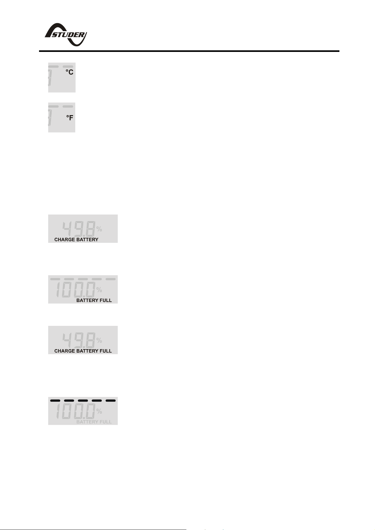
CHARGE BATTERY (flashing). The state-ofcharge of the battery has dropped below the
adjusted ‘discharge floor’ (see Function F05). The
battery needs to be recharged as soon as
possible.
BATTERY FULL (flashing). The battery is fully
charged and the battery charger possibly operates
in the ‘float’ stage. The charger may be turned off.
The monitor is synchronized with the battery!
CHARGE BATTERY FULL (flashing). Charge the
battery completely full! This indication will arise
when the SBM-01 decides that the monitor needs
to be synchronized with the battery (for example
after a number of charge/discharge cycles, after a
reset or right after power-up).
STATE OF CHARGE BARGRAPH. This bar
represents the state of charge in five steps until
the 'discharge floor' (see Function F05) is reached.
A fully charged battery is represented by five bar
segments. When the battery is discharged, the bar
disappears and the message 'CHARGE
BATTERY' will arise on the display.
15
Page 17

SBM-01 high precision battery monitor
4. ADVANCED FEATURES
Besides the general functionality as described in chapter 3, the SBM-01
offers some additional advanced features too. These features are
reviewed in the next three chapters.
4.1 History data
The SBM-01 is able to store so-called special events as history data in
it’s memory. The next events are stored as history data :
H01 : The automatically calculated charge-efficiency-factor (CEF).
H02 : The average discharge in Ah. This value will be recalculated
after each synchronization.
H03 : The deepest discharge in Ah.
H04 : Number of charge/discharge cycles.
H05 : The number of ‘synchronisations’. This is the number of times
the battery is fully charged meeting the charged-parameters
condition.
H06 : The number of full discharges (reaching a state-of-charge of
0.0%).
H07 : The number of undervoltage alarms.
H08 : The number of overvoltage alarms.
H09 : The average discharge in %. This value will be recalculated
after each synchronization.
H10 : The deepest discharge in %.
The information stated above can be recalled in the ‘history readout’.
This readout can be activated by pressing the SETUP key for five
seconds. After this five seconds, a flashing ‘H01’ shall appear on the
display. With the < and > selection keys the value of H01 can be
displayed. By pressing the SETUP (next) key the next history event, in
this case ‘H02’, can be selected. To jump back to normal operating
mode, the SETUP key must be pressed for three
seconds.
4.2 Reset menu
The Reset menu allows you to reset individual SBM-01 Functions and
the History Data to their factory defaults. Resetting the History Data is
recommended to be used only when replacing your batteries. If you
16
Page 18

SBM-01 high precision battery monitor
replace your batteries with the exact same brand and type, it is only
necessary to reset the History Data and leave the Functions unchanged.
To activate the Reset menu, press the SETUP key for eight seconds.
After eight seconds a flashing “rSt.F” (“Reset Functions”) appears on the
display. To change the value to “On” or “OFF,” press the < and > keys.
By pressing the SETUP (next) key, “rSt.H” (“Reset History”) can be
selected. Again, to change the value to “On” or “OFF,” press the < and >
keys. To apply the actual reset of whichever item is set to “On,” press the
SETUP key for three seconds until the display stops flashing and the
battery monitor jumps back to normal operation mode again.
When the monitor is secured by the Super-lock, the Functions and
History Data cannot be reset and “S.Loc” will appear on the display after
pressing the < or the > key. If the SBM-01 operates in the Reset menu
and no keys are pressed for 90 seconds, the monitor will jump back to
normal operating mode automatically, without resetting the
Functions and/or History Data.
4.3 PC-link
Each SBM-01 offers the possibility to communicate with a Personal
Computer. However, the optional external communications interface kit is
required for this feature. This communications interface only needs to be
connected when actually communicating with the SBM-01, to avoid
unnecessary power consumption. With the dedicated SBM-01 Windows
95/98/Me/2k/XP
®
software, the user can simultaneously display all
parameters. The SBM-01 can also be fully programmed via this link,
while the complete Function setup can be saved to disk. Furthermore
history data can be readout, the SBM-01 can be tested and the superlock can be (de-)activated.
4.4 Super-lock
With the super-lock feature, the setup menu of the SBM-01 can be
completely locked and secured by a password. In super-lock mode the
history data cannot be erased. The normal operating mode is not
affected by the super-lock and the Functions in the setup menu can be
reviewed, but not altered. Only the user/installer knowing the password,
can unlock the SBM-01 via the PC-link.
17
Page 19

SBM-01 high precision battery monitor
The super-lock must not be confused with the setup-lock (Function F20).
The big difference between the two is that anybody can disable the
setup-lock, even without communication between SBM-01 and PC. The
setup-lock is used to avoid accidental altering of the Function values.
While the super-lock can only be (de-)activated via the PC-link using a
unique password. The super-lock feature is primarily meant for warranty
purposes.
5. TROUBLESHOOTING GUIDELINE
PROBLEM REMEDY OR SUGGESTION
The monitor doesn’t operate (no
display)
- Check monitor- and battery
side connections.
- Make sure the inline fuses are
installed and not blown.
- Check battery voltage. Battery
might be flat. Vbatt must be
> 8VDC.
- Try to restart the monitor by
removing/placing the fuses
again.
Current readout gives wrong
polarity (positive current instead
of negative when discharging)
- Current sense leads from the
shunt are reversed. Check the
installation guide.
The monitor resets all the time - Check the wiring for corrosion
and/or loose contacts.
- Battery might be flat or
defective.
No changes can be made in the
setup-mode
- Check if the setup-lock is OFF
(Function F20)
- Your SBM-01 might be
locked by the super- lock. Ask
the installer for the password to
unlock the monitor using the
PC-link.
Not all readouts in normal mode
can be selected
- Installer has cancelled some
parameter readouts using the
administrator software with the
PC-link.
‘CHARGE BATTERY’ or - Charge battery full
18
Page 20

‘CHARGE BATTERY FULL’
keeps on flashing
State-of-charge and/or time-togo readout not accurate
Display returns ‘- - - -‘ in
temperature readout
Display returns ‘Lo’ repeatedly
regardless of readout selection
Display returns ‘Hi’ repeatedly
regardless of readout selection
Battery voltage readout is highly
inaccurate
SBM-01 high precision battery monitor
(synchronize your battery with
the monitor)
- Check the charged-parameters
in Functions F02, F03 and F04
for possible wrong settings.
- Check if all current is flowing
through the shunt (the negative
terminal of the battery may only
contain the wire going to the
battery-side of the shunt!).
- Current sense leads from the
shunt are reversed.
- Check battery capacity in
Function F01
- Check CEF in Function F09
- Check Peukert Exponent in
Function F10
- Check Battery temperature in
Function F11
- Check Temperature coefficient
in Function F12
- Connection with temperature
sensor is lost. Check for failed
connections and/or cable
damage.
- Undervoltage detected. Input
voltage is below the value
entered in Function F07.
- Overvoltage detected. Input
voltage exceeds the value
entered in Function F08.
- Check prescaler setting in
Function F16
If none of the above remedies will help solving the problem you
encounter, it’s best to contact your local dealer for further help.
5.1 Warranty
Studer Innotec (Studer) warrants this product to be free from defects in
workmanship or materials for 24 months from the date of purchase.
19
Page 21

SBM-01 high precision battery monitor
During this period Studer will repair the defective product free of charge.
Studer is not responsible for any costs of the transport of this product.
This warranty is void if the product has suffered any physical damage or
alteration, either internally or externally, and does not cover damage
arising from improper use
1)
or from use in an unsuitable environment.
This warranty will not apply where the product has been misused,
neglected, improperly installed or repaired by anyone other than Studer.
Studer is not responsible for any loss, damage or costs arising from
improper use, use in an unsuitable environment or improper installing,
setup and malfunctioning of the product.
Since Studer cannot control the use and installation (according to local
regulations) of their products, the customer is always responsible for the
actual use of these products. Studer products are not designed for use
as cricital components in life support devices or systems, that can
potentially harm humans and/or the environment. Studer keeps the right
to change product specifications without previous notice.
1)
Examples of improper use are :
- too high input voltage applied
- wrong shunt connection
- applying battery voltage to shunt input
- mechanically stressed enclosure or internals due to harsh handling
and/or incorrect packaging
- contact with any liquids or oxidation caused by condensation
6. TECHNICAL DATA
SBM-01 TECHNICAL DATA
Supply voltage range 9 .. 35VDC
Supply current @Vin=24VDC
6mA
without BL
@Vin=12VDC
8mA
without BL
Input voltage range 0 .. 35VDC
Input current range -500 .. +500A
20
Page 22

SBM-01 high precision battery monitor
Battery capacity range 20 .. 2000Ah
Operating temperature range
0 .. 50°C
Readout resolution :
voltage (0 .. 35V)
current (0 .. 200A)
current (200 .. 500A)
Amphours (0 .. 200Ah)
Amphours (200 .. 2000Ah)
state-of-charge (0 .. 100%)
time-to-go (0 .. 100hrs)
time-to-go (100 .. 240hrs)
± 0.01V
± 0.1A
± 1A
± 0.1Ah
± 1Ah
± 0.1%
± 1minute
± 1hr
temperature (0 .. 50°C) ± 1°C
Voltage measurement accuracy
Current measurement accuracy
± 0.3%
± 0.4%
Dimensions :
frontpanel 65 x 65mm
body diameter
∅ 52mm
total depth 72mm
Equipped with : - Potential free alarm contact
- 500A/50mV current shunt
Accessories : - SBM-01 Connection kit :
- SBM-01 temperature sensor
- SBM-01 RS232 comm.
interface kit
- SBM-01 USB comm. interface
kit
- 1:5 voltage prescaler
Note : the given specifications are subject to change without notice
21
Page 23

SBM-01 high precision battery monitor
6.1 Declaration of conformity
MANUFACTURER : Studer Innotec
ADDRESS : Rue des Casernes 57
CH – 1950 Sion
Switzerland
Declares that the following products :
PRODUCT TYPE : BATTERY MONITOR
MODEL : SBM-01
Conforms to the requirements of the following Directives of the European
Union :
EMC Directive 89/336/EEC
Automotive Directive 95/54/EC
The above product is in conformity with the following harmonized
standards :
- EN50081-1 : 1994 EMC - Generic Emissions Standard
- EN50082-1 : 1997 EMC - Generic Immunity Standard
22
Page 24

SBM-01 high precision battery monitor
INHALT
1. DER BATTERIEMONITOR - GRUNDLAGEN . . . . . . . . . 24
1.1 Wozu dient der Batteriemonitor? . . . . . . . . . . . 24
1.2 Wie funktioniert der SBM-01? . . . . . . . . . . . . . 24
2. EINRICHTUNG DES SBM-01 . . . . . . . . . . . . . . . . 25
2.1 Ladewirkungsgrad(CEF) . . . . . . . . . . . . . . . 26
2.2 Peukert-Exponent . . . . . . . . . . . . . . . . . . 26
2.3 Ladeparameter . . . . . . . . . . . . . . . . . . . 28
2.4 Synchronisierung des SBM-01. . . . . . . . . . . . . 28
2.5 Übersicht über die Funktionen. . . . . . . . . . . . . 29
3. NORMALBETRIEB DES SBM-01 . . . . . . . . . . . . . . 35
4. SPEZIALFUNKTIONEN . . . . . . . . . . . . . . . . . . 37
4.1 History-Daten . . . . . . . . . . . . . . . . . . . 37
4.2 Menü „Zurücksetzen“ . . . . . . . . . . . . . . . . 38
4.3 PC-link . . . . . . . . . . . . . . . . . . . . . . 39
4.4 Super-lock . . . . . . . . . . . . . . . . . . . . . 39
5. FEHLERSUCHE . . . . . . . . . . . . . . . . . . . . . 40
5.1 Garantie . . . . . . . . . . . . . . . . . . . . . . 42
6. TECHNISCHE DATEN. . . . . . . . . . . . . . . . . . . 43
6.1 Konformitätserklärung . . . . . . . . . . . . . . . . 44
23
Page 25

SBM-01 high precision battery monitor
1. DER BATTERIEMONITOR - GRUNDLAGEN
1.1 Wozu dient der Batteriemonitor?
Für Batterien gibt es eine Vielzahl von Verwendungsmöglichkeiten,
meistens dienen sie dazu, Energie für eine spätere Verwendung zu
speichern. Aber wie soll man erkennen, wieviel Energie noch in einer
Batterie gespeichert ist? Von außen läßt sich das nicht ablesen.
Batterietechnologie wird oft unterbewertet, einige grundlegende
Kenntnisse über Batterien und ein gutes Kontrollsystem sind jedoch
unerläßlich, um eine maximale Lebensdauer Ihrer teuren Batterien zu
gewährleisten. Die Lebensdauer von Batterien hängt von vielen Dingen
ab und wird durch ungenügende Aufladung, Überladung, zu starke oder
zu schnelle Entladung und eine zu hohe Umgebungstemperatur verkürzt.
Durch eine Kontrolle Ihrer Batterie mit Hilfe eines hochentwickelten
Batteriemonitors wie dem SBM-01 erhält der Benutzer wertvolle
Informationen, so daß er gegebenenfalls geeignete Maßnahmen
ergreifen kann. Auf diese Weise wird die Lebensdauer der Batterie
verlängert und die Investition in den SBM-01 zahlt sich schnell aus.
1.2 Wie funktioniert der SBM-01?
Die Kapazität einer Batterie wird in Amperestunden (Ah) gemessen. Bei
einer Batterie, die beispielsweise 20 Stunden lang eine Stromstärke von
5 Ampere liefert, wird die Kapazität mit 100 Ah (5 x 20 = 100)
angegeben. Der SBM-01 mißt kontinuierlich den bestehenden Stromfluß
in und aus der Batterie und kann so die Energiemenge, die aus der oder
in die Batterie fließt, berechnen. Da jedoch das Alter der Batterie, die
Entladestromstärke sowie die Temperatur die Kapazität einer Batterie
beeinflussen, ist die Amperestundenanzeige nicht verläßlich. Die gleiche
100 Ah-Batterie liefert, wenn sie in zwei Stunden vollständig entladen
wird, lediglich 56 Ah. Wie man sieht, ist die Kapazität der Batterie fast
halbiert. Dieses Phänomen wird Peukert-Effizienz genannt (siehe auch
Kapitel 2.2). Wenn außerdem noch die Temperatur der Batterie zu
niedrig ist, sinkt die Kapazität sogar noch weiter. Das ist der Grund,
weshalb einfache Amperestundenzähler oder Spannungsmesser den
genauen Ladezustand nicht anzeigen können.
Der SBM-01 kann sowohl die verbrauchten Amperestunden (nicht
kompensiert) als auch den derzeitigen Ladezustand (kompensiert durch
Peukert-Effizienz, Lade-Effizienz und Temperatur) anzeigen. Durch die
24
Page 26

SBM-01 high precision battery monitor
Bestimmung des Ladezustandes kann der Zustand Ihrer Batterie wohl
am besten dargestellt werden. Dieser Parameter wird in Prozent
angegeben, wobei 100 % bedeutet, daß Ihre Batterie vollständig
aufgeladen ist, 0,0 % steht für eine vollständige Entladung. Diese
Anzeige ist mit der Benzinanzeige eines Autos vergleichbar.
Der SBM-01 gibt auch an, wie lange die derzeitige Ladung der Batterie
noch schätzungsweise anhält (Ladedauer-Anzeige). Dabei handelt es
sich um den Zeitraum, bis die Batterie wieder aufgeladen werden muß.
Wenn die Batterieladung stark schwankt, sollten Sie sich nicht all zu sehr
auf diese Anzeige verlassen, da es sich hierbei nur um eine momentane
Anzeige handelt, die lediglich als Anhaltspunkt dienen soll. Zur exakten
Batteriekontrolle sollten Sie immer nur die Ladezustandsanzeige
verwenden.
Neben der Hauptfunktion des SBM-01, der tatsächlichen
Ladezustandsanzeige, bietet dieser Batteriemonitor noch eine Reihe von
anderen Funktionen. Die Anzeige der tatsächlichen Spannung, der
Stromstärke und der Temperatur der Batterie (mit optionalem
Temperatursensor), die Fähigkeit, History-Daten zu speichern, die PCKompatabilität und die Super-lock sind nur einige der vielen Funktionen
des SBM-01. Diese Funktionen werden im einzelnen in den jeweiligen
Kapiteln des Handbuchs erläutert.
2. EINRICHTUNG DES SBM-01
Bevor Sie dieses Kapitel lesen, stellen Sie bitte sicher, daß Ihr SBM01 vollständig entsprechend der beiliegenden Anleitung eingebaut
wurde.
Nachdem Ihr SBM-01 eingebaut wurde, muß der Batteriemonitor jetzt
auf Ihr Batteriesystem eingestellt werden. Bevor jedoch die Funktionen
des Setup-Menüs besprochen werden, gehen wir in den nächsten
Kapiteln zunächst auf vier Punkte ein. Es ist wichtig, daß die Benutzer
des SBM-01 einige Kenntnisse auf diesem Gebiet erwerben, um mit der
Batteriekontrolle vertraut zu werden. Die eigentlichen Setup-Funktionen
werden in Kapitel 2.5 ‘Übersicht über die Funktionen’ erläutert.
25
Page 27

SBM-01 high precision battery monitor
2.1 Ladewirkungsgrad (CEF)
Nicht die gesamte Energie, die bei der Batterieaufladung an die Batterie
übertragen wird, steht bei der Entladung der Batterie auch wieder zur
Verfügung. Die Ladeeffizienz einer brandneuen Batterie liegt bei etwa
90%, was bedeutet, daß 10 Amperestunden (Ah) auf die Batterie
übertragen werden müssen, damit tatsächlich 9Ah in
der Batterie
gespeichert werden. Diese Effizienzgröße nennt man Ladewirkungsgrad
(CEF), der mit dem Alter der Batterie abnimmt. Der SBM-01 berechnet
diesen CEF der Batterie automatisch.
2.2 Peukert-Exponent
Wie bereits in Kapitel 1.2 erwähnt, gibt die Peukert-Effizienz an, daß die
Amperestundenzahl abnimmt, wenn man eine Batterie schneller als mit
der 20 Stunden Nennleistung entlädt. Dieser Verlust an Batteriegröße
wird “Peukert-Exponent” genannt und kann von 1.00 auf 1.50 in der
Funktion F10 eingestellt werden. Je höher der Peukert-Exponent, desto
schneller verringert sich bei steigendem Entladerate die Batteriegröße.
Eine ideale (theoretische) Batterie hat einen Peukert-Exponent von 1.00,
und ist unabhängig von der Entladungsstromstärke. Natürlich gibt es
solche Batterien nicht und eine Einstellung von 1.00 dient nur dazu, die
Peukert-Kompensierung beim SBM-01 zu umgehen.
Die Standard-Einstellung für den Peukert-Exponenten ist 1.25, ein
akzeptabler Mittelwert für die meisten Bleisäure-Batterien. Für die
präzise Batteriekontrolle ist es jedoch unerläßlich, den richtigen PeukertExponenten einzugeben. Wenn bei Ihrer Batterie kein Peukert-Exponent
angegeben wurde, können Sie ihn mit Hilfe anderer Angaben, die auf
Ihrer Batterie angegeben sein müssen, berechnen. Die PeukertGleichung lautet wie folgt:
1log2log
2log1log
IItt−
Cp = I
n
⋅t wenn der Peukert-Exponent ‘n’ =
−
Die Batterieangaben, die Sie für die Berechnung des PeukertExponenten benötigen, sind die festgelegte Batteriekapazität (20
Stunden Entladerate
(1)
) und zum Beispiel ein 5 Stunden Entladerate
(2)
(C5 rating). Schauen Sie sich das nachstehende Berechnungsbeispiel
zur Festlegung des Peukert-Exponenten unter Verwendung der beiden
bekannten Größen an:
26
Page 28

−
SBM-01 high precision battery monitor
5 Stunden Entladerate, C5 = 75Ah
→ t1 = 5Std.
→ I1 = 75Ah/5Std. = 15A
20 Stunden Entladerate, C20 = 100Ah (festgelegte Kapazität)
→ t2 = 20Std.
→ I2 = 100Ah/20hr = 5A
5log20log
Peukert-Exponent n =
−
= 1,26
5log15log
(1)
Die Batterienennleistung kann auch als 10 Stunden oder 5 Stunden
Entladerate bezeichnet werden.
(2)
Der 5 Stunden Entladerate ist in diesem Fall willkürlich gewählt.
Stellen Sie sicher, daß Sie neben der Nennkapazität C20 (niedrige
Entladestromstärke) eine zweite Entladerate mit einer erheblich
höheren Entladestromstärke auswählen.
Wenn überhaupt keine Nennkapazitäten angegeben wurden, können Sie
Ihre Batterie mit Hilfe einer “konstanten Entladebank” überprüfen. Auf
diese Weise kann neben der 20 Std.-Nennleistung (die in den meisten
Fällen übliche Batteriekapazität
(1)
) eine zweite Entladerate erzielt
werden. Diese zweite Entladerate kann bestimmt werden, indem man
eine vollständig geladene Batterie bei einer konstanten Stromstärke
entlädt, bis die Batterie 1,75 V je Zelle erreicht (d.h. 10,5 V bei einer 12
V-Batterie oder 21 V bei einer 24 V-Batterie). Hier ein
Berechnungsbeispiel:
Eine 200Ah Batterie wird mit einer konstanten Stromstärke von 20 A
entladen, so daß nach 8,5 Stunden 1,75 V/Zelle erreicht werden.
Somit, → t1 = 8.5Std.
→ I1 = 20A
20Std. Entladerate, C20 = 200Ah
→ t2 = 20 Std.
→ I2 = 200Ah/20Std. = 10A
27
Page 29

−
SBM-01 high precision battery monitor
5.8log20log
Peukert-Exponent n =
−
= 1,23
10log20log
2.3 Ladeparameter
Entsprechend der zunehmenden Ladespannung und der abnehmenden
Ladestromstärke kann entschieden werden, ob die Batterie voll geladen
ist oder nicht. Wenn die Batteriespannung innerhalb einer vordefinierten
Zeit über einem bestimmten Niveau liegt, und die Ladestromstärke
innerhalb des selben Zeitraumes unter einem bestimmten Niveau liegt,
kann davon ausgegangen werden, daß die Batterie vollständig geladen
ist. Diese Spannungs- und Stromstärkeniveaus sowie die vordefinierte
Zeit werden “Ladeparameter” genannt. Im allgemeinen beträgt der
Spannungsladeparameter bei einer 12V-Bleisäurebatterie 13,2 V und der
Stromstärkenladeparameter 2,0 % der gesamten Batteriekapazität (z.B.
4A bei einer 200 Ah-Batterie). Bei den meisten Batteriesystemen ist eine
Ladeparameterzeit von 4 Minuten ausreichend. Wir weisen darauf hin,
daß diese Parameter für den korrekten Betrieb Ihres SBM-01 sehr
wichtig sind und in den jeweiligen Funktionen richtig eingestellt werden
müssen.
2.4 Synchronisierung des SBM-01
Um eine verläßliche Anzeige des Ladezustandes der Batterie zu
erzielen, muß der Batteriemonitor regelmäßig mit der Batterie und dem
Ladegerät Synchronisiert werden. Dies geschieht durch die vollständige
Aufladung der Batterie. Schaltet das Ladegerät auf “Erhaltungsladung”,
so betrachtet es die Batterie als voll. Der SBM-01 muß jetzt die Batterie
ebenfalls als vollständig geladen betrachten, so daß der
Amperestundenzähler auf Null gestellt werden kann und die
Ladeanzeige auf 100,0 %. Durch die präzise Einstellung der
Ladeparameter im SBM-01 kann der Batteriemonitor automatisch mit
dem Ladegerät Synchronisiert werden, wenn der Erhaltungsmodus
(float-stage) erreicht wird. Das Bereich der Ladeparameter ist groß
genug, um den SBM-01 auf die meisten Batterieauflademethoden
einstellen zu können.
Falls es nicht möglich sein sollte, den SBM-01 auf die
Ladungsalgorithmen des installierten Ladegerätes einzustellen, kann der
Benutzer den Batteriemonitor auch manuell Synchronisieren, wenn die
28
Page 30

SBM-01 high precision battery monitor
Batterie vollständig geladen ist. Dies geschieht durch gleichzeitiges
Drücken der Tasten < und > für drei Sekunden. Wenn der
Batteriemonitor manuell gleichgeschaltet wird, erfolgt keine automatische
Berechnung des CEF. Nach einer Unterbrechung der Spannung des
SBM-01 muß der Batteriemonitor immer
Synchronisiert werden –
ansonsten kann ein korrektes Funktionieren nicht gewährleistet
werden !
Wir weisen darauf hin, daß durch das regelmäßige Aufladen Ihrer
Batterie (mindestens einmal im Monat) diese nicht nur synchron mit dem
SBM-01 bleibt, sondern auch erhebliche Kapazitätsverluste vermieden
werden können, die die Lebensdauer Ihrer Batterie erheblich schmälern.
2.5 Übersicht über die Funktionen
Die Werkseinstellungen des SBM-01 sind für ein durchschnittliches 12VBleisäurebatteriesystem mit 200 Ah geeignet. Somit muß in den meisten
Fällen zur Kontrolle eines 12V-Systems lediglich die Funktion der
Batteriekapazität geändert werden (F01). Falls andere Batteriesorten
verwendet werden, stellen Sie bitte sicher, daß alle relevanten Daten
bekannt sind, um die SBM-01 Funktionen korrekt einzurichten.
Der SBM-01 kann über zwanzig verschiedene Einstellungen “Funktionen” - vollständig eingerichtet werden. Vor der Einrichtung des
SBM-01 muß der Setup-Modus aktiviert werden. Der Setup-Modus wird
durch drei-sekundenlanges
Drücken der Taste SETUP aktiviert.
Daraufhin blinkt die Anzeige, was darauf hinweist, daß der Setup-Modus
aktiviert wurde. Durch wiederholtes Drücken der Taste SETUP kann die
gewünschte Funktion gewählt werden. Die gewählte Funktion wird als
Fxx angezeigt, wobei xx die Nummer der Funktion bezeichnet.
Mit den Tasten < und > kann der Wert der gewählten Funktion geändert
werden. Durch wiederholtes Drücken der Taste SETUP wird die nächste
Funktion gewählt. Zur Speicherung der geänderten Einstellungen im
SBM-01 wird die Taste SETUP drei Sekunden lang gedrückt, bis die
Anzeige nicht mehr blinkt und der Batteriemonitor auf den normalen
Betriebsmodus zurückspringt. Wenn der SBM-01 im Setupmodus steht
und 90 Sekunden lang keine Taste gedrückt wird, springt der Monitor
automatisch auf den normalen Betriebsmodus zurück, ohne
möglicherweise geänderte Einstellungen zu speichern.
29
Page 31

SBM-01 high precision battery monitor
In der untenstehenden Tabelle werden alle Funktionen des SBM-01 mit
einer kurzen Erklärung im Überblick dargestellt. Wir empfehlen, im
Zweifelsfall die Funktionen F04, F05, F06, F09, F10, F11, F12, F13, F14,
F15, F16, F17, F18 und F20 nicht zu ändern. Bei den meisten
Batteriesystemen sollte die Einstellung der Werte der Funktionen F01,
F02, F03, F07 und F08 ausreichen.
F01 : Batteriekapazität in Amperestunden (Ah). Dies ist die
erforderliche Kapazität bei einem Entladerate von 20 Std. und
einer Temperatur von 20 °C (oder 68°F).
Standard : 200Ah
Bereich : 20 – 2000Ah
Stufe : 1Ah
F02 : Spannungsladeparameter. Die Batteriespannung muß über
diesem Spannungsniveau liegen, damit die Batterie als
vollständig geladen betrachtet werden kann. Stellen Sie
sicher, daß der Spannungsladeparameter immer leicht unter
der Spannung liegt, bei der das Ladegerät die Aufladung der
Batterie beendet (üblicherweise 0,1 V oder 0,2 V unter der
“Erhaltungsstufe“ des Ladegerätes).
Standard : 13,2V
Bereich : 8,0 – 33,0V
Stufe : 0,1V
F03 : Stromstärkenladeparameter. Wenn der
Stromstärkenladeparameter unter diesem Prozentsatz der
Batteriekapazität liegt (siehe F01), kann die Batterie als
vollständig geladen betrachtet werden. Stellen Sie sicher, daß
der Stromstärkenladeparameter immer höher ist als die
Mindeststromstärke, bei der das Ladegerät die Batterie erhält
oder die Aufladung beendet.
Standard : 2,0%
Bereich : 0,5 – 10,0%
Stufe : 0,5%
F04 : Ladeparameterzeit. Dies ist die Zeit, in der die Ladeparameter
(wie in F02 und F03 beschrieben) erreicht werden müssen,
damit die Batterie als vollständig geladen betrachtet werden
kann.
30
Page 32

SBM-01 high precision battery monitor
Standard : 4 Minuten
Bereich : 1 – 4 Minuten
Stufe : 1 Minute
F05 : “Entlade”-Alarm AN (Entladestufe). Wenn der prozentuale
Ladestatus
unter diesen Wert fällt, wird der Alarm ausgelöst
und die CHARGE BATTERY Anzeige erscheint, um darauf
hinzuweisen, daß die Batterie wieder aufgeladen werden
muß. Die Berechnung der Ladedauer (time-to-go) und der
Ladezustandsanzeige Bar sind ebenfalls mit diesem Wert
verbunden. Es wird empfohlen, diesen Wert auf etwa 50,0 %
zu halten.
Standard : 50,0%
Bereich : 0,0 – 99,0%
Stufe : 1,0%
F06 : “Entlade”- Alarm AUS. Wenn der prozentuale Ladestatus
diesen Wert überschreitet und ein Alarm ausgelöst wird, wird
dieser sofort wieder deaktiviert. Wenn FULL gewählt wurde,
wird der Alarm deaktiviert, sobald die Ladeparameter erreicht
sind.
Standard : 80,0%
Bereich : 0,0 – 100,0% / FULL
Stufe : 1,0%
F07 : “Unterspannungs”-Alarm. Wenn die Batteriespannung unter
diesen Wert fällt, erscheint nach 10 Sekunden die Nachricht
LO (niedrig) auf der Anzeige, und der Alarm wird ausgelöst.
Standard : 10,5V
Bereich : OFF / 8,0 – 33,0V
Stufe : 0,1V
F08 : “Überspannungs”-Alarm. Wenn die Batteriespannung diesen
Wert überschreitet, erscheint nach 5 Sekunden die Nachricht
Hi (hoch) auf der Anzeige, und der Alarm wird ausgelöst.
Standard : 16,0V
Bereich : OFF / 10,0 – 35,0V
Stufe : 0,1V
F09 : Ladewirkungsgrad (CEF). Es ist empfehlenswert, diesen Wert
auf AU (automatische Berechnung) zu halten. Der Wert A90
stellt die automatische Berechnung wieder auf 90% zurück.
31
Page 33

SBM-01 high precision battery monitor
Eine manuelle Einstellung wird durch Uxx gekennzeichnet,
wobei xx die Ladeeffizienz darstellt. (weitere Informationen
über den CEF finden Sie in Kapitel 2.1)
Standard : AU
Bereich : U50 – U99 / AU / A90
Stufe : 1%
F10 : Peukert-Exponent (Entladeeffizienz). Wenn dieser unbekannt
ist, wird empfohlen, den Wert auf 1,25 zu halten. Ein Wert von
1,00 sperrt die Peukert-Kompensierung. Weitere
Informationen sowie ein Berechnungsbeispiel zum PeukertExponenten finden Sie in Kapitel 2.2.
Standard : 1,25
Bereich : 1,00 – 1,50
Stufe : 0,01
F11 : Batterietemperatur. In dieser Funktion kann die
Durchschnittstemperatur der Batterie eingestellt werden. Der
Wert AU ermöglicht eine automatische Temperaturmessung,
vorausgesetzt, daß ein externer Temperatursensor mit dem
SBM-01 verbunden ist. Auch wird die Temperaturanzeige im
normalen Modus eingeschaltet. Wird AU gewählt, die
Verbindung mit dem Temperatursensor jedoch unterbrochen,
erscheinen vier Bindestriche (- - - -). Es erfolgen die internen
Temperaturausgleichsberechnungen unter Verwendung der
Voreinstellung von 20 °C . Dieser Funktion kann nur
Eingestellt werden in °C. Mit der folgendes Formeln können
Sie °C ↔ °F Konvertieren :
T
(°F)
= (T
x 1.8) + 32 und T
(°C)
(°C)
= (T
- 32) / 1.8
(°F)
Standard : 20 °C
Bereich : 0 – 50 / AU
Stufe : 1 °C
F12 : Temperaturkoeffizient. Dies ist der Prozentsatz, um den sich
die Batteriekapazität mit der Temperatur verändert. Dieser
Wert wird in der Einheit ‘%cap/°C’ oder Prozent der Kapazität
je Grad Celsius angegeben. Die Standardeinstellung beträgt
0.5 %cap/°C, was den meisten Batterien entspricht. Die
Einstellung OFF schaltet den Temperaturausgleich ab.
Standard : 0.5 %cap/°C
32
Page 34

SBM-01 high precision battery monitor
Bereich : OFF / 0.05 – 0.95 %cap/°C
Stufe : 0.05 %cap/°C
F13 : Durchschnittliche Ladedauer. Gibt das Zeitfenster in Minuten
an, mit dem der durchschnittsbildende Filter arbeitet. Die
Auswahl der richtigen Zeit hängt von Ihrer Anlage ab. Der
Wert 0 schaltet den Filter ab und bewirkt eine sofortige
Anzeige (Echtzeit), wobei jedoch die angezeigten Werte stark
fluktuieren können. Durch die Auswahl der höchsten
Zeitanzeige (12 Minuten) wird sichergestellt, daß die
langfristigen Ladefluktuationen bei den
Ladedauerberechnungen mit berücksichtigt werden.
Standard : 3 Minuten
Bereich : 0 / 3 / 6 / 9 / 12 Minuten
F14 : Stromstärkenschwelle. Wenn die gemessene Stromstärke
unter diesen Wert sinkt, wird sie als Null Ampere gemessen.
Mit dieser Funktion ist es möglich, sehr geringe Stromstärken
auszuschalten, die die langfristige Ladezustandsanzeige
negativ beeinflussen können. Wenn beispielsweise die
derzeitige langfristige Stromstärke +0,05A beträgt und der
Batteriemonitor aufgrund von Interferenz oder kleineren
Verschiebungen –0,05 A mißt, kann der SBM-01 langfristig
fälschlicherweise anzeigen, daß die Batterie neu aufgeladen
werden muß. Wenn in diesem Fall die Funktion 14 auf 0,1
gestellt wird rechnet der SBM-01 mit 0,0A, so daß keine
falschen Annahmen getroffen werden können. Durch
Einstellung auf 0,0 wird diese Funktion ausgeschaltet.
Standard : 0.0A
Bereich : 0.0 – 2.0A
Stufe : 0.1A
F15 : Temperatur Einheit. Diese Funktion erlaubt den Wechsel
zwischen Grad Celsius und Grad Fahrenheit für die
Temperaturanzeige.
Standard : °C
Bereich : °C / °F
F16 : Spannungsteiler einstellung. Diese Funktion ist nur dann
wichtig, wenn ein optionaler Spannungsteiler (Voltage
prescaler) an dem Batteriespannungsmeßeingang des SBM01 installiert wurde. Die Spannungsladeparameter, die
33
Page 35

SBM-01 high precision battery monitor
Unterspannungs- und Überspannungalarmeinstellungen sind
mit dieser Funktion verbunden. Wenn Sie keinen
Spannungsteiler verwenden, bitte diesen Wert nicht ändern!
Standard : 1-1
Bereich : 1-1 / 1-5 / 1-10
F17 : Anzeige-Modus (Hintergrundbeleuchtung).
Hintergrundbeleuchtungsdauer in Sekunden, nachdem eine
Taste auf dem SBM-01 gedrückt wurde. Darüber hinaus kann
der SBM-01 so eingestellt werden, daß die
Hintergrundbeleuchtung immer AN oder AUS bleibt. Mit der
Einstellung AU wird die Hintergrundbeleuchtung automatisch
eingeschaltet, wenn die Lade-/Entladestromstärke über 1A
hinausgeht oder wenn eine Taste gedrückt wird.
Standard : 30 Sekunden
Bereich : OFF / 10 – 60 / ON / AU
Stufe : 10 Sekunden
F18 : Polarität der Alarmrelaiskontakte. Diese Funktion erlaubt den
Wechsel zwischen Kontakt normal offen (NO) und Kontakt
normal geschlossen (NC). Es ist zu beachten, dass die NCEinstellung zu einer etwas höheren Stromaufnahme des
SBM-01 im Normalbetrieb führt.
Standard : NO
Bereich : NO / NC
F19 : Firmware-Version. Zeigt die Firmware-Version des SBM-01
an. Keine Änderungen möglich.
Standard : x.xx
F20 : Setup-Verriegelung. Wenn diese Funktion auf ON geschaltet
ist, sind alle Funktionen (bis auf diese Funktion) gesperrt und
können nicht mehr geändert werden.
Standard : OFF
Bereich : OFF / ON
Wenn alle erforderlichen Änderungen durchgeführt und im Setup-Modus
überprüft worden sind, müssen Sie nur noch in den normalen
Betriebsmodus zurückschalten, indem Sie die SETUP-Taste drei
Sekunden lang gedrückt halten. Ihr SBM-01 ist jetzt betriebsbereit!
34
Page 36

SBM-01 high precision battery monitor
3. NORMALBETRIEB DES SBM-01
Im normalen Betriebsmodus kann der SBM-01 die sechs wichtigsten
Parameter Ihres Gleichstromsystems anzeigen. Wählen Sie die
gewünschten Parameter mit Hilfe der Tasten < und >.
Batteriespannung (V). Mit Hilfe dieser Anzeige können Sie
den Ladezustand der Batterie grob einschätzen. Eine 12VBatterie gilt als leer, wenn sie unter Entladebedingungen eine
Spannung von 10,5V nicht mehr aufrechterhalten kann.
Stromstärke (A). Sie zeigt die tatsächliche Stromstärke an,
die in die oder aus der Batterie fließt. Eine
Entladestromstärke wird als negativer Wert angezeigt (Strom,
der aus der Batterie heraus fließt). Wenn beispielsweise ein
DC-AC Wechselrichter 5 Ampere von der Batterie abzieht,
wird dies in der Anzeige mit –5,0A angezeigt.
Verbrauchte Amperestunden (Ah) zeigt die Anzahl an
Amperestunden an, die von der Batterie verbraucht worden
sind. Bei einer vollständig geladenen Batterie wird dieser
Wert mit 0,0Ah angezeigt (synchronisiertes System). Wurde
beispielsweise drei Stunden lang eine Stromstärke von 12A
von der Batterie verbraucht, so wird dies mit –36,0Ah
angezeigt.
Ladezustand (%). Dies ist der beste Weg, den tatsächlichen
Ladezustand der Batterie zu überprüfen. Diese Anzeige zeigt
an, über wieviel Energie die Batterie tatsächlich noch verfügt.
Eine vollständig geladene Batterie wird mit 100.0% angezeigt,
während die Anzeige bei einer vollständig entladenen Batterie
0.0% lautet.
35
Page 37

SBM-01 high precision battery monitor
Restladedauer (h:m) ist eine Schätzung, wie lange die
Batterie die derzeitige Ladung noch aufrecht erhalten kann,
bevor sie neu aufgeladen werden muß. Dieser Zeitraum wird
in Stunden angegeben (über 100 Std.) oder im hh:mm Format
(unter 100 Std.).Eine Restladedauer von 15 Std. und 45
Minuten wird als 15:45 h:m und eine Restladedauer von 120
Std. wird als 120 h angegeben. Während des Ladens der
Batterie zeigt das Display ---- h, was bedeutet, dass keine
Betriebsdauer berechnet werden kann.
Temperatur (°C oder °F) zeigt die derzeitige Temperatur der
Batterie an. Diese Anzeige wird automatisch aktiviert, wenn
die Funktion 11 auf AU steht und der optionale
Temperaturfühler mit dem SBM-01 verbunden ist. Wird die
Verbindung zu dem Temperaturfühler unterbrochen, zeigt die
Anzeige wieder vier Bindestriche (- - - -). Die
Temperatureinstellung kann mit der Funktion F15 gewählt
werden.
Der SBM-01 zeigt auch an, wenn die Batterie neu geladen werden muß
oder wenn die Batterie vollständig geladen ist. Diese Hinweise erfolgen
durch die CHARGE BATTERY FULL Hinweise unten auf der Anzeige
und die Ladezustandanzeige Balken oben auf der Anzeige. In der
untenstehenden Tabelle werden die vier möglichen Kombinationen
dieser Hinweise erklärt.
CHARGE BATTERY (blinkend). Der Ladezustand
der Batterie ist unter das eingestellte
"Entladestufe” gesunken (siehe Funktion F05). Die
Batterie muß so bald wie möglich aufgeladen
werden.
BATTERY FULL (blinkend). Die Batterie ist
vollständig geladen und das Ladegerät arbeitet
möglicherweise im “Erhaltungsmodus”. Das
Ladegerät kann ausgeschaltet werden. Der
Monitor ist mit der Batterie synchronisiert!
36
Page 38

SBM-01 high precision battery monitor
CHARGE BATTERY FULL (blinkend). Laden Sie
die Batterie vollständig auf! Diese Anzeige
erscheint, wenn der SBM-01 entscheidet, daß der
Monitor mit der Batterie synchronisiert werden
muß (zum Beispiel nach einer Reihe von Lade/Entladezyklen, nach erneutem Reset oder direkt
nach dem Einschalten der Stromversorgung).
LADEZUSTANDSANZEIGE. Dieser Balken zeigt
den Ladezustand in fünf Stufen bis zum Erreichen
des 'Entladepunkts' an (siehe Funktion F05). Eine
vollständig geladene Batterie wird durch fünf
Balkenelemente dargestellt. Ist die Batterie
entladen, verschwindet der Balken und im Display
wird die Meldung 'CHARGE BATTERY' (Batterie
laden) angezeigt.
4. SPEZIALFUNKTIONEN
Neben den in Kapitel 3 beschriebenen allgemeinen Funktionen verfügt
der SBM-01 auch über einige zusätzliche Spezialfunktionen. Diese
Funktionen werden in den nächsten drei Kapiteln vorgestellt.
4.1 History-Daten
Der SBM-01 kann sich sogenannte besondere Vorkommnisse merken
und als History-Daten speichern. Dazu gehören die folgenden Daten:
H01 : Der automatisch berechnete Ladewirkungsgrad (CEF).
H02 : Die durchschnittliche Entladung in Ah. Dieser Wert wird nach
jeder Synchronisierung neu berechnet.
H03 : Die tiefste Entladung in Ah.
H04 : Anzahl der Lade-/Entladezyklen.
H05 : Die “Ausgleichshäufigkeit”. Damit ist die Anzahl der
Zeitpunkte gemeint, an denen die Batterie vollständig geladen
ist und den Zustand der Ladeparameter erreicht.
H06 : Die Anzahl der vollständigen Entladungen (wobei ein
Ladezustand von 0,0% erreicht wird).
H07 : Die Anzahl der Unterspannungs-Alarmmeldungen.
H08 : Die Anzahl der Überspannungs-Alarmmeldungen.
H09 : Die durchschnittliche Entladung in %. Dieser Wert wird nach
37
Page 39

SBM-01 high precision battery monitor
jeder Synchronisierung neu berechnet.
H10 : Die tiefste Entladung in %.
Die oben genannten Daten können in der “History-Anzeige” abgerufen
werden. Diese Anzeige wird aktiviert, indem die SETUP Taste des SBM01 fünf
Sekunden lang gedrückt werden. Nach diesen fünf Sekunden
erscheint ein blinkendes ‘H01’ auf der Anzeige. Mit Hilfe der Tasten <
und > selection kann der Wert von H01 angezeigt werden. Durch
Drücken der SETUP Taste (next) kann die nächste History-Information
angewählt werden, in diesem Fall ‘H02’. Um zum normalen
Betriebsmodus zurückzukehren, müss die SETUP Taste des SBM-01
drei
Sekunden lang gedrückt werden.
4.2 Menü „Zurücksetzen“
Mithilfe des Menüs „Zurücksetzen“ können Sie einzelne Funktionen
des SBM-01 sowie die History-Daten auf die
Werkseinstellungen zurücksetzen. Das Zurücksetzen der
History-Daten wird nur beim Auswechseln der Akkus empfohlen.
Wenn die neuen Akkus exakt die gleiche Marke und den gleichen
Typ aufweisen wie die bisherigen, müssen nur die History-Daten
ersetzt werden. Die Funktionen können unverändert beibehalten
werden.
Zum Aktivieren des Menüs „Zurücksetzen“ halten Sie die Taste
SETUP acht Sekunden lang gedrückt. Nach acht Sekunden wird der
blinkende Eintrag „rSt.F“ („Reset Functions“ - „Funktionen
Zurücksetzen“) angezeigt. Zur Auswahl von „On“ (Ein) oder „Off“ (Aus)
drücken Sie die Tasten < und >.
Durch Drücken der Taste SETUP (weiter), kann „rSt.H“ („Reset
History“ - „History-Daten zurücksetzen“) ausgewählt werden. Zur
Auswahl von „On“ oder „Off“ drücken Sie erneut die Tasten < und >.
Um die geänderten Einstellungen für alle Elemente zu übernehmen,
die jetzt auf „Ein“ gesetzt sind, drücken Sie drei Sekunden lang die
Taste SETUP, bis die Anzeige nicht mehr blinkt und der SBM-01
wieder in den normalen Betriebsmodus wechselt.
Wenn der SBM-01 durch Superlock gesichert ist, können die
Funktionen und die History-Daten nicht zurückgesetzt werden. Nach
Drücken der Tasten < oder > wird entsprechend „S.Loc“ angezeigt.
Wenn beim SBM-01 im Modus „Zurücksetzen“ 90
38
Page 40

SBM-01 high precision battery monitor
Sekunden lang keine Tasten gedrückt werden, wechselt dieser
automatisch in den normalen Betriebsmodus zurück, ohne die
Funktionen und/oder die History-Daten zurückzusetzen.
4.3 PC-link
Jeder SBM-01 verfügt über die Möglichkeit, mit einem PC zu
kommunizieren. Allerdings ist hierfür das optionale externe
Kommunikationsschnittstellenbausatz erforderlich. Dieses
Kommunikations-Interface braucht aber nur dann angeschlossen zu
werden, wenn tatsächlich mit dem SBM-01 kommuniziert werden soll. So
kann unnötiger Stromverbrauch vermieden werden. Mit der
entsprechenden SBM-01 Windows 95/98/Me/2k/XP
®
Software kann der
Benutzer gleichzeitig alle Parameter anzeigen lassen. Der SBM-01 kann
darüber hinaus vollständig über diese PC-link programmiert werden,
während das vollständige Funktions-Setup auf einer Disk gespeichert
werden kann. Außerdem ist es möglich, die History-Daten anzuzeigen,
den SBM-01 zu testen und die Superlock-Sperre zu (de-) aktivieren.
4.4 Super-lock
Das Setup-Menü des SBM-01 kann mit der „Superlock“ vollständig
gesperrt und mit einem Paßwort gesichert werden. Im Superlock-Modus
können auch die History-Daten nicht gelöscht werden. Der normale
Betriebsmodus ist von der Superlock-Modus nicht betroffen und die
Funktionen des Setup-Menüs können überprüft, allerdings nicht geändert
werden. Allein der Benutzer/installierende Person, dem/der das Paßwort
bekannt ist, kann den SBM-01 über den PC-Link entriegeln.
Die Superlock darf nicht mit der Setup-Verriegelung (Funktion F20)
verwechselt werden. Der große Unterschied ist hierbei, daß die
Setupverriegelung von jedem aufgehoben werden kann, auch ohne
Kommunikationsverbindung zwischen dem SBM-01 und dem PC. Sie
soll unbeabsichtigte Änderungen der Funktionswerte verhindern. Die
Superlock kann dagegen ausschließlich über die PC-link und nur unter
Angabe eines einzigartigen Paßwortes aufgehoben werden. Sie dient in
erster Linie Haftungszwecken.
39
Page 41

SBM-01 high precision battery monitor
5. FEHLERSUCHE
PROBLEM LÖSUNG ODER VORSCHLAG
Der Monitor funktioniert nicht
(keine Anzeige)
- Überprüfen Sie die
Verbindungen von Monitor und
Batterie.
- Stellen Sie sicher, daß die
Sicherungen installiert und
nicht herausgesprungen sind.
- Überprüfen Sie die
Batteriespannung. Die Batterie
könnte leer sein. Der Wert
Vbatt muß > 8VDC sein.
- Versuchen Sie, den Monitor
erneut einzuschalten, indem
Sie die Sicherungen
herausnehmen/wieder
einsetzen.
Stromstärkenanzeige zeigt
falsche Polung an (positiv statt
negativ beim Entladen)
Der Monitor stellt sich ständig
neu ein
- Shuntverkabelung sind falsch
gepolt. Sehen Sie noch einmal
in die Aufbauanleitung.
- Überpüfen Sie, ob die
Verbindungen rostig und/oder
lose sind.
- Die Batterie könnte leer oder
defekt sein.
Im Setup-Modus sind keine
Änderungen möglich.
- Überprüfen Sie, ob die Setup-
Verriegelung auf OFF steht
(Funktion F20)
- Die Superlock könnte
aktivieert sein. Fragen Sie den
Einrichter nach dem Paßwort,
damit Sie den Monitor mit Hilfe
der PC-link entriegeln können.
Im Betriebsmodus können nicht
alle
Anzeigen angewählt
werden.
- Der Einrichter hat über die PC-
link einige Parameteranzeigen
mit der Administrator-Software
gelöscht
Ständig blinkende Anzeige
`CHARGE BATTERY’ oder
- Batterie vollständig aufladen
(Batterie mit dem Monitor
40
Page 42

SBM-01 high precision battery monitor
‘CHARGE BATTERY FULL’ synchronisieren)
- Überprüfen Sie die
Ladeparameter in den
Funktionen F02, F03 und F04
auf falsche Einstellungen.
Ladezustands- und/oder
Restladedaueranzeige sind nicht
exakt
- Prüfen Sie, ob der gesamte
Strom durch den Shunt fließt
(der Minuspol der Batterie darf
nur den Draht zur Batterieseite
des Shunts aufnehmen).
- Die Bekabelung vom Shunt
sind falsch gepolt.
- Prüfen Sie die Batteriekapazität
in Funktion F01
- Prüfen Sie den CEF in
Funktion F09
- Prüfen Sie den Peukert-
Exponenten in Funktion F10
- Prüfen Sie die
Batterietemperatur in Funktion
F11
- Prüfen Sie den Temperatur-
Koeffizienten in Funktion F12
Temperaturanzeige kehrt zu
‘- - - -‘ zurück
- Verbindung mit dem
Temperatursensor ist
unterbrochen. Suchen sie nach
unterbrochenen Verbindungen
und/oder Kabelschäden.
Im Display erscheint
wiederholend ’Lo’ ungeachtet
der Anzeigenauswahl
- Unterspannung wahr-
genommen. Batteriespannung
ist unterhalb des in Funktion
F07 eingetragenen Wert.
Im Display erscheint
wiederholend ’Hi’ ungeachtet der
Anzeigenauswahl
- Überspannung wahr-
genommen. Batteriespannung
übersteigt den in Funktion
F08 eingetragenen Wert.
Batteriespannungsanzeige ist
sehr ungenau
- Prüfen Sie die Einstellung des
Spannungsteilers in Funktion
F16
41
Page 43

SBM-01 high precision battery monitor
Wenn sich Ihr Problem mit Hilfe der obigen Vorschläge nicht beheben
läßt, wenden Sie sich bitte an Ihren nächsten Vertragshändler.
5.1 Garantie
Studer Innotec (Studer) garantiert, daß dieser Batteriemonitor 24 Monate
nach dem Kaufdatum keine Verarbeitungs- oder Materialschäden
aufweist. Während dieser Zeit wird Studer den Batteriemonitor im Fall
von Schäden kostenlos reparieren. Studer übernimmt keine
Transportkosten für den Batteriemonitor.
Dieser Garantieanspruch verfällt, wenn der Batteriemonitor außen oder
innen körperliche Beschädigungen oder Veränderungen aufweist. Ferner
gilt die Garantie nicht für Beschädigungen, die auf eine unsachgemäße
Verwendung
1)
, oder die Verwendung in einem ungeeigneten Umfeld
zurückzuführen sind.
Die Garantie kommt nicht zum Tragen, wenn das Produkt falsch benutzt,
vernachlässigt, unsachgemäß installiert oder von einem anderen als
dem Studer repariert wurde. Studer kann nicht für eventuelle Verluste,
Beschädigungen oder Kosten, die mit einer unsachgemäßen
Verwendung, einer Verwendung in einer ungeeigneten Umgebung, einer
unsachgemäßen Installation, Gebraucher Einstellungen oder einer
Funktionsstörung des Batteriemonitors in Zusammenhang stehen,
verantwortlich gemacht werden.
Da Studer den Gebrauch und die Montage (gemäß lokaler
Bestimmungen) von Studer-Produkten nicht kontrollieren kann, ist der
Kunde für den eigentlichen Gebrauch von Studer-Produkten immer
selbst verantwortlich. Studer-Produkte sind nicht vorgesehen für die
Verwendung als kritische Komponenten in Geräten zur Lebenserhaltung
oder in Systemen, die möglicherweise Menschen verletzen und/oder die
Umwelt schädigen können. Studer behält sich das Recht vor
Produktspezifizierungen ohne Vorankündigung zu ändern.
1)
Beispiele für unsachgemäßen Gebrauch sind :
- Verwendung zu hoher Eingangsspannung
- Falsches Shunt Verbindung
- Verwendung Batteriespanning an Shunt Eingang
- Mechanische Überlastung des Gehäuses oder der Innenteile
verursacht durch grobe Handhabung und/oder unsachgemäßes
42
Page 44

SBM-01 high precision battery monitor
Verpacken
- Kontakt mit irgendwelchen Flüssigkeiten oder Oxidation verursacht
durch Kondensation
6. TECHNISCHE DATEN
SBM-01 TECHNISCHE DATEN
Versorgungsspannungsbereich 9 .. 35VDC
Versorgungs @Vin=24VDC
6mA
stromstärke ohne HGB
@Vin=12VDC
8mA
ohne HGB
Eingangsspannungsbereich 0 .. 35VDC
Eingangsstromstärke-Bereich -500 .. +500A
BatterieKapazitätsbereich 20 .. 2000Ah
Betriebstemperaturbereich
0 .. 50°C
Auflösung der Anzeige :
Spannung (0 .. 35V)
Stromstärke (0 .. 200A)
Stromstärke (200 .. 500A)
Ampstd. (0 .. 200Ah)
Ampstd. (200 .. 2000Ah)
Ladezustand (0 .. 100%)
Restladedauer (0 .. 100Std)
Restladedauer (100 .. 240Std)
± 0.01V
± 0.1A
± 1A
± 0.1Ah
± 1Ah
± 0.1%
± 1Minute
± 1Std.
Temperatur (0 .. 50°C) ± 1°C
Meßgenauigkeit der Spannung
Meßgenauigkeit der Stromstärke
± 0.3%
± 0.4%
Abmessungen :
Frontplatte 65 x 65mm
Durchmesser
∅ 52mm
Gesamttiefe 72mm
ausgestattet mit : - Potentialfreiem Alarmkontakt
43
Page 45

SBM-01 high precision battery monitor
- 500A/50mV-Shunt
Optionen : - SBM-01 Anschlussbausatz
- SBM-01 temperaturfühler
- SBM-01 RS232 komm.
schnittstellenbausatz
- SBM-01 USB komm.
schnittstellenbausatz
- 1:5 Spannungsteiler
Anmerkung: die obigen Daten können ohne Benachrichtigung geändert
werden.
6.1 Konformitätserklärung
Siehe Seite 22
44
Page 46

SBM-01 high precision battery monitor
TABLE DES MATIERES
1. INTRODUCTION AU CONTROLEUR DE BATTERIE . . . . . 46
1.1 Pourquoi contrôler une batterie ? . . . . . . . . . . . 46
1.2 Comment fonctionne le SBM-01 ? . . . . . . . . . . . 46
2. PARAMETRAGE DU SBM-01 . . . . . . . . . . . . . . . 47
2.1 Facteur d'Efficacté de Charge (CEF) . . . . . . . . . . 47
2.2 L'exposant de Peukert . . . . . . . . . . . . . . . . 48
2.3 Paramètres de "pleine charge" . . . . . . . . . . . . 49
2.4 Synchronisation du SBM-01 . . . . . . . . . . . . . 50
2.5 Vue d'ensemble des Fonctions . . . . . . . . . . . . 50
3. FONCTIONNEMENT GENERAL . . . . . . . . . . . . . . 57
4. FONCTIONS AVANCEES . . . . . . . . . . . . . . . . . 59
4.1 Mémoire historique . . . . . . . . . . . . . . . . . 59
4.2 Menu Reset (Réinitialiser) . . . . . . . . . . . . . . 59
4.3 Interface PC . . . . . . . . . . . . . . . . . . . . 60
4.4 Super-lock . . . . . . . . . . . . . . . . . . . . . 61
5. GUIDE DE DEPANNAGE . . . . . . . . . . . . . . . . . 62
5.1 Garantie . . . . . . . . . . . . . . . . . . . . . . 63
6. CARACTERISTIQUES TECHNIQUES . . . . . . . . . . . . 64
6.1 Déclaration de conformité. . . . . . . . . . . . . . . 65
45
Page 47

SBM-01 high precision battery monitor
1. INTRODUCTION AU CONTROLEUR DE BATTERIE
1.1 Pourquoi contrôler une batterie ?
De nombreuses applications très diverses utilisent des batteries,
généralement pour stocker de l'énergie pour une utilisation ultérieure.
Mais comment connaître la quantité d'énergie contenue dans la batterie
? C'est impossible à voir. La technologie des batteries est souvent trop
simplifiée à l'excès, mais quelques connaissances de base et une
surveillance régulière sont essentielles pour assurer une longévité
maximale à des équipements si onéreux. La durée de vie des batteries
dépend de nombreux facteurs, tels que la sous-charge, la surcharge, la
décharge trop profonde, la décharge trop rapide ou une température
ambiante trop élevée. En mettant votre batterie sous la surveillance de
l'appareil très sophistiqué qu'est le contrôleur de batterie SBM-01, vous
disposez d'informations essentielles pour agir en temps utile. Ainsi, en
prolongeant la durée de vie de votre batterie, le SBM-01 sera rapidement
amorti.
1.2 Comment fonctionne le SBM-01 ?
La capacité d'une batterie s'exprime en Ampères-heures (Ah). Par
exemple, on dit d'une batterie capable de délivrer un courant de 5 A
pendant 20 heures qu'elle a une capacité de 100Ah (5 x 20 = 100). Le
SBM-01 mesure en permanence les courants nets entrant ou sortant de
la batterie de manière à calculer la quantité d'énergie extraite ou ajoutée.
Mais une lecture en Ah ne suffit pas, puisque l'âge, l'intensité courant de
décharge et la température affectent aussi la capacité de la batterie. La
même batterie déchargée entièrement en deux heures seulement ne
fournirait que 56Ah en raison de l'intensité de décharge plus élevée.
La capacité de la batterie est ainsi divisée presque par deux. Ce
phénomène s'appelle le rendement de Peukert (voir aussi au chapitre
2.2). De plus, lorsque la température de la batterie est basse, sa
capacité est encore plus amoindrie. C'est pourquoi un simple voltmètre
ou compteur d'ampères-heures ne permettront pas de déterminer avec
précision l'état réel de la batterie.
Le SBM-01 peut afficher aussi bien les Ah consommés (non-compensés)
et l'état de charge réel (compensée pour le rendement de Peukert, le
rendement de charge et la température). La meilleure façon d'évaluer la
capacité de votre batterie est de lire l'état de charge. Ce paramètre est
46
Page 48

SBM-01 high precision battery monitor
donné en pour-cent, avec 100,0% = une batterie pleine et 0,0% = une
batterie vide.
Le SBM-01 estime aussi la durée pendant laquelle la batterie peut
continuer à alimenter les utilisations en cours (indication d'autonomie
restante). Ceci correspond en fait au temps restant avant qu'une
nouvelle recharge sera nécessaire. Si la puissance demandée varie
fortement, il vaut mieux ne pas se fier à cette indication puisqu'elle est
instantanée et doit donc servir uniquement à titre indicatif. Nous
recommandons vivement l'utilisation de l'information de l'état de charge
pour une surveillance précise de la batterie.
En plus de sa fonction 'de base' d'affichage de l'état réel de la batterie, le
SBM-01 offre de nombreuses autres fonctionnalités, dont: l'affichage de
la tension, du courant et de la température (si la sonde de température
optionnelle est installée) réels de la batterie, une mémoire historique, la
liaison à un ordinateur (PC) et la fonction 'Super-lock'. Ces fonctions sont
décrites plus en détail dans les chapitres spécifiques du présent manuel.
2. PARAMETRAGE DU SBM-01
Avant de procéder au paramétrage, vérifiez que votre SBM-01 est
installé conformément au guide d'installation joint.
Une fois le contrôleur de batterie SBM-01 installé, il faut le paramétrer
pour votre système de batteries. Avant d'aborder les fonctions du menu
de paramétrage, quatre points très importants sont exposés. Il est
indispensable en tant qu'utilisateur d'un contrôleur SBM-01 de se
familiariser avec ces 4 notions. Les fonctions spécifiques du menu de
paramétrage sont décrites au chapitre 2.5 ‘Introduction aux fonctions'?.
2.1 Facteur d'Efficacité de Charge (CEF)
Pas toute l'énergie transférée dans une batterie lors de sa charge sera
disponible lors de sa décharge. L'efficacité de charge d'une batterie
neuve est d'environ 90%, ce qui signifie qu'il faut transférer 10Ah vers la
batterie pour que 9Ah soit réellement stocké dans
la batterie. Ce
phénomène est désigné Facteur d'Efficacité de charge (en anglais
Charge-Efficiency-Factor ou CEF).Il diminue avec l'âge de la batterie. Le
SBM-01 calcule automatiquement le CEF de la batterie.
47
Page 49

−
−
SBM-01 high precision battery monitor
2.2 L'exposant de Peukert
Le rendement Peukert décrit le phénomène de baisse de la capacité
d'une batterie lorsqu'elle est déchargée plus vite qu'à son intensité
nominale de 20 h. Cette baisse de capacité, désignée ‘l'exposant de
Peukert', peut être paramétrée entre 1,00 et 1,50 par la Fonction F10.
Plus l'exposant de Peukert est élevé, plus la capacité de la batterie
diminue avec l'augmentation de l'intensité de décharge. Une batterie
idéale (théorique) aurait un exposant Peukert de 1,00 et serait insensible
au niveau d'intensité de décharge. Bien sûr, une telle batterie n'existe
pas, et la valeur 1,00 sert uniquement à désactiver la compensation
Peukert du SBM-01.
La valeur par défaut de l'exposant de Peukert est 1,25, ce qui représente
une valeur moyenne acceptable pour la plupart des types de batteries.
Cependant, pour une surveillance précise de votre batterie, il est
essentiel de sélectionner la bonne valeur d'exposant de Peukert. Si
celui-ci n'est pas connu, vous pouvez le calculer à partir d'autres
caractéristiques qui doivent être fournies avec la batterie. La formule de
Peukert est la suivante :
1log2log
Cp = I
n
⋅t avec l'exposant de Peukert ‘n’ =
2log1log
IItt−
Les caractéristiques nécessaires au calcul de l'exposant de Peukert sont
les capacités nominales de la batterie données pour une décharge en 20
(1)
h
(cas le plus fréquent) et, par exemple, pour une décharge en 5 h
(2)
.
L'exemple ci-après vous montre comment calculer l'exposant de Peukert
à partir de ces deux éléments :
taux en 5h, C5 = 75Ah
→ t1 = 5h
→ I1 = 75Ah/5h = 15A
taux en 20h, C20 = 100Ah (capacité nominale)
→ t2 = 20h
→ I2 = 100Ah/20h = 5A
5log20log
exposant de Peukert n =
−
= 1,26
5log15log
48
Page 50

−
(1)
Notez que la capacité nominale de la batterie peut également être
SBM-01 high precision battery monitor
spécifié pour d'autres durées, par exemple 100 h ou 10 h.
(2)
Le chiffre de 5h dans cet exemple est pris arbitrairement. Veillez à
sélectionner un deuxième taux avec une intensité de décharge
substantiellement plus élevée.
En l'absence de toute valeur, vous pouvez mesurer votre batterie au
moyen d'un banc de charge. Ainsi vous obtenez une deuxième valeur en
plus de celle en 20 h, qui représente la capacité nominale de la batterie
dans la plupart des cas
(1)
. Cette deuxième valeur peut être déterminée
en déchargeant une batterie pleine sous un courant constant, jusqu'à
1,75V par cellule (soit 10,5V pour une batterie de 12V ou 21V pour une
batterie de 24V). Un exemple de ce calcul est présenté ci-après :
On décharge une batterie de 200Ah sous un courant constant de 20A et
la valeur de 1,75V/cellule est atteinte après 8,5 heures.
Donc, → t1 = 8,5h
→ I1 = 20A
taux en 20h, C20 = 200Ah
→ t2 = 20hr
→ I2 = 200Ah/20h = 10A
5.8log20log
exposant de Peukert n =
−
= 1,23
10log20log
2.3 Paramètres de "pleine charge"
Il est possible de déterminer si une batterie est pleine ou non en se
basant sur l'augmentation de la tension de charge et sur la diminution du
courant de charge. Lorsque la tension de la batterie est supérieure à un
niveau donné pendant une durée déterminée, alors que le courant de
charge est inférieur à un niveau donné pour la même durée, on
considère que la batterie est pleine. Ces niveaux de tension et de
courant, ainsi que la durée prédéterminée sont désignés "paramètres de
pleine charge. En général, pour une batterie de 12V, les paramètres de
pleine charge sont de 13,2V pour la tension (pour une batterie de 12V) et
de 2,0% de la capacité totale de la batterie pour le courant (soit 4A pour
49
Page 51

SBM-01 high precision battery monitor
une batterie de 200Ah). Pour la plupart des systèmes il suffit que ces
niveaux soient présents pendant 4 minutes. Notez que ces paramètres
sont très importants pour un fonctionnement correct de votre SBM-01, et
doivent être paramétrés correctement dans les Fonctions
correspondantes.
2.4 Synchronisation du SBM-01
Pour une indication précise de l'état de charge de la batterie, il faut
synchroniser régulièrement le contrôleur de batterie avec la batterie et
avec le chargeur. Ceci se fait en chargeant totalement la batterie.
Lorsque le chargeur fonctionne en mode ‘float’, celui-ci considère que la
batterie est pleine. A ce stade, il faut que le SBM-01 aussi considère la
batterie pleine, pour remettre à zéro le compteur d'Ampères-heures et
afficher 100,0% comme valeurd'état de charge. En réglant avec
précision les paramètres de pleine charge dans le SBM-01, celui-ci peut
se synchroniser automatiquement sur le chargeur lorsqu'il atteint le
mode ‘float’. La plage des paramètres de pleine charge est suffisamment
large pour pouvoir adapter le SBM-01 à la plupart des méthodes de
charge.
S'il n'est pas possible de régler le SBM-01 pour l'algorithme de charge
du chargeur installé, l'utilisateur peut toujours synchroniser le contrôleur
de batterie manuellement au moment où la batterie est pleine. Pour ceci,
maintenez enfoncées les deux touches < et > simultanément pendant
trois secondes. Lorsque vous synchronisez le contrôleur manuellement,
le CEF n'est pas calculé automatiquement. Après toute interruption
dans l'alimentation du SBM-01, il faut systématiquement le
synchroniser pour qu'il puisse fonctionner correctement.
Notez que lorsque vous chargez totalement votre batterie régulièrement
(au moins une fois par mois), non seulement celle-ci restera
synchronisée avec le SBM-01, mais vous réduirez aussi la perte
substantielle de capacité de votre batterie qui diminue sa longévité.
2.5 Vue d'ensemble des Fonctions
Les paramétrages d'usine du SBM-01 conviennent à un système de
batteries plomb-acide classique de 12V/200Ah. Donc dans la plupart des
cas, pour surveiller un système 12V, la seule Fonction qui pourrait
nécessiter une modification est la capacité de la batterie (F01). Si vous
50
Page 52

SBM-01 high precision battery monitor
utilisez d'autres types de batteries, assurez-vous de disposer de toutes
les caractéristiques nécessaires pour paramétrer correctement les
Fonctions du SBM-01.
L'utilisateur dispose de vingt paramètres, désignés Fonctions, permettant
de paramétrer le SBM-01 de manière très précise. Pour procéder à ce
paramétrage, il faut d'abord activer le mode paramétrage. Pour ce faire,
appuyez sur la touche SETUP pendant trois secondes. L'afficheur
clignote indiquant que le mode paramétrage est activé. Pour afficher la
Fonction désirée, appuyez autant de fois que nécessaire sur la touche
SETUP. La Fonction est affichée sous la forme Fxx avec xx = le numéro
de la Fonction. Les touches < et > permettent de modifier la valeur de la
Fonction affichée. Pour afficher la Fonction suivante, appuyez à nouveau
sur la touche SETUP. Pour sauvegarder les nouvelles valeurs dans la
mémoire du SBM-01, appuyez sur la touche SETUP pendant trois
secondes jusqu'à ce que l'afficheur s'arrête de clignoter et que le
contrôleur repasse en mode 'normal'. Si aucune touche n'est actionnée
pendant 90 secondes alors que le SBM-01 est en mode paramétrage,
celui-ci revient automatiquement en mode 'normal', sans sauvegarder les
modifications.
Le tableau ci-après présente toutes les Fonctions du SBM-01 avec une
description succincte. En cas de doute, nous vous recommandons de ne
pas modifier les Fonctions F04, F05, F06, F09, F10, F11, F12, F13, F14,
F15, F16, F17, F18 ou F20. Pour la plupart des systèmes de batterie, il
suffira de modifier les valeurs des Fonctions F01, F02, F03, F07 et F08.
F01 : Capacité de la batterie en Ampères-heures (Ah). Ceci doit
être la capacité pour une décharge en 20h et à 20 °C (68 °F).
Par défaut : 200Ah
Plage : 20 – 2000Ah
Pas : 1Ah
F02 : Paramètre de "pleine charge" pour la tension. La tension de
la batterie doit être supérieure à cette valeur pour que celle-ci
soit considérée pleine. Veillez à fixer ce paramètre toujours
légèrement en dessous de la tension de fin de charge à
laquelle le chargeur termine la charge de la batterie
(généralement 0,1V ou 0,2V en dessous de la tension ‘float’
du chargeur).
Par défaut : 13,2V
51
Page 53

SBM-01 high precision battery monitor
Plage : 8,0 – 33,0V
Pas : 0,1V
F03 : Paramètre de "pleine charge" pour le courant. Lorsque le
courant de charge est inférieur à ce pourcentage de la
capacité de la batterie (voir F01), on considère qu'elle est
pleine. Veillez à fixer ce paramètre toujours au dessus du
courant de charge minimal d'entretien de la batterie, ou de
celui où le chargeur arrête la charge.
Par défaut : 2,0%
Plage : 0,5 – 10,0%
Pas : 0,5%
F04 : Durée paramètres de "pleine charge". Ceci est le temps
durant lequel les paramètres "pleine charge" (décrits en F02
et F03) doivent persister, pour considérer la batterie comme
étant pleine.
Par défaut : 4 minutes
Plage : 1 – 4 minutes
Pas : 1 minutes
F05 : Déclenchement Alarme Batterie basse (seuil de décharge).
Lorsque le pourcentage de l'état de charge
tombe sous cette
valeur, le relais d'alarme est activé et l'indication CHARGE
BATTERY (chargez batterie) clignote sur l'afficheur - il faut
recharger la batterie. Le calcul du temps restant et le
diagramme à barres de l’état de charge sont également liés à
cette valeur. Nous vous recommandons de garder cette
valeur à environ 50,0%.
Par défaut : 50,0%
Plage : 0,0 – 99,0%
Pas : 1,0%
F06 : Arrêt Alarme Batterie basse. Lorsque le pourcentage de l'état
de charge se trouve au-dessus de cette valeur alors que le
relais d'alarme est activé, celui-ci sera désactivé. Lorsque
FULL (pleine) est sélectionné, le relais d'alarme est désactivé
quand les paramètres de "pleine charge" sont atteints.
Par défaut : 80,0%
Plage : 0,0 – 100,0% / FULL (pleine)
Pas : 1,0%
52
Page 54

SBM-01 high precision battery monitor
F07 : Alarme Tension basse. Lorsque la tension de la batterie
tombe sous cette valeur, après une temporisation de 10
secondes, le message Lo (basse) est affiché et le relais
d'alarme est activé.
Par défaut : 10,5V
Plage : OFF (Arrêt) / 8,0 – 33,0V
Pas : 0,1V
F08 : Alarme Tension haute. Lorsque la tension de la batterie
dépasse cette valeur, après une temporisation de 5
secondes, le message Hi (haute) est affiché et le relais
d'alarme est activé.
Par défaut : 16,0V
Plage : OFF (Arrêt) / 10,0 – 35,0V
Pas : 0,1V
F09 : Facteur d'Efficacité de Charge (Charge efficiency factor,
CEF). Nous vous recommandons de garder ce paramètre sur
AU (calcul automatique). Si vous paramétrez A90, le calcul
utilise un facteur fixe de 90%?. Le paramétrage manuel est
affiché sous la forme Uxx avec xx = le Facteur d'Efficacité de
Charge. (voir aussi chapitre 2.1)
Par défaut : AU
Plage : U50 – U99 / AU (Automatique) / A90
Pas : 1%
F10 : Exposant de Peukert (rendement en décharge). Si vous ne
connaissez pas cette valeur pour vos batteries, nous
recommandons de conserver la valeur 1,25. La valeur 1,00
désactive la compensation de Peukert. (Voir aussi chapitre
2.2 )
Par défaut : 1,25
Plage : 1,00 – 1,50
Pas : 0,01
F11 : Température de la batterie. Cette Fonction permet de
paramétrer la température moyenne de la batterie. Sur AU, la
mesure de la température est automatique mais nécessite
une sonde externe de température (option) permettant aussi
l'affichage de la température en mode normal. Si AU est
sélectionné et que la liaison vers la sonde de température est
53
Page 55

SBM-01 high precision battery monitor
interrompue, quatre tirets (- - - -) sont affichés et les calculs
de compensation de température internes utilisent la valeur
°
par défaut de 20
C. Cette fonction ne peut se régler qu’en
°C. Utilisez les formules suivantes pour convertir des °C en
°F : T
(°F)
= (T
x 1.8) + 32 et T
(°C)
(°C)
= (T
- 32) / 1.8 .
(°F)
°
Par défaut : 20
C
Plage : 0 – 50 / AU (Automatique)
°
Pas : 1
C
F12 : Coefficient de température. Ceci est la variation de la
capacité de la batterie en pourcentage et en fonction de sa
température. L'unité pour cette valeur est ‘%cap/°C’ ou
pourcentage de capacité par degré Celsius. La valeur par
défaut est 0,5%cap/°C, ce qui est typique pour la plupart des
batteries. Sur OFF, la compensation en fonction de la
température est désactivée.
°
Par défaut : 0,5 %cap/
Plage : OFF (Arrêt) / 0,05 – 0,95 %cap/
Pas : 0,05 %cap/
C
°
C
°
C
F13 : Fenêtre de calcul d'autonomie restante. Spécifie la durée en
minutes utilisée par le filtre pour calculer la moyenne. Le
choix de la durée dépend de votre installation. La valeur 0
désactive le filtre et fournit une lecture instantanée (en temps
réel), mais les valeurs affichées sont susceptibles de varier
fortement. La valeur la plus élevée (12 minutes) garantit la
prise en compte des fluctuations d'intensité lentes dans le
calcul d'autonomie restante.
Par défaut : 3 minutes
Plage : 0 / 3 / 6 / 9 / 12 minutes
F14 : Seuil de courant. Lorsque le courant mesuré tombe sous
cette valeur, il sera considéré comme étant nul. Cette fonction
permet de s'affranchir des courants très faibles qui peuvent
dégrader à long terme l'information de l'état de charge dans
un environnement perturbé. Par exemple si le courant réel à
long terme est de +0,05A et que le contrôleur de batterie
mesure –0,05A en raison des perturbations ou de légers
décalages, à long terme le SBM-01 pourrait indiquer à tort
que la batterie a besoin d'être rechargée. Dans ce cas, si la
54
Page 56

SBM-01 high precision battery monitor
Fonction 14 est réglée sur 0,1, le SBM-01 utilise 0,0A dans
son calcul, éliminant ainsi les erreurs. La valeur 0,0 désactive
cette Fonction.
Par défaut : 0,0A
Plage : 0,0 – 2,0A
Pas : 0,1A
F15 : Sélection de l’unité de température. Cette fonction permet de
choisir entre des degrés Celsius (°C) et des degrés
Fahrenheit (°F) pour la lecture de la température.
Par défaut : °C
°
Plage :
C / °F
F16 : Indexeur de tension. Cette Fonction n'est importante qu'en
présence d'un indexeur optionnel installé sur l'entrée de
mesure de tension batterie du SBM-01.
Cette option permet de modifier la portée de mesure de
tension. Les valeurs paramétrées de "pleine charge" pour la
tension et des alarmes de tension basse et haute sont liées à
cette Fonction. Ne modifiez pas cette valeur si vous n'utilisez
pas d'indexeur
Par défaut : 1-1
Plage : 1-1 / 1-5 / 1-10
F17 : Mode d'affichage (rétro-éclairage). La durée, en secondes,
pendant laquelle le rétro-éclairage reste allumé après une
impulsion sur une touche quelconque du SBM-01. Il peut
aussi être paramétré pour être en permanence soit ON
(Allumé) soit OFF (Eteint). Sur AU, l'éclairage est activé
automatiquement quand le courant de charge/décharge
dépasse 1A ou lorsque l'on appuie sur une touche
quelconque.
Par défaut : 30 secondes
Plage : OFF / 10 – 60 / ON / AU (Auto.)
Pas : 10 secondes
F18 : Polarité du contact du relais de l’alarme. Cette fonction
permet de choisir entre un contact normalement ouvert (NO)
ou normalement fermé (NC). Ầ noter que le réglage NC
augmente légèrement le courant d’alimentation du SBM-01
en mode de fonctionnement normal.
55
Page 57

SBM-01 high precision battery monitor
Par défaut : NO
Plage : NO / NC
F19 : Version du matériel. Affiche la version du SBM-01. Ce
paramètre ne peut pas être modifié.
Par défaut : x.xx
F20 : Verrouillage. Lorsque cette Fonction est sur ON (Marche),
toutes les fonctions de paramétrage (sauf celle-ci) sont
verrouillées et ne peuvent pas être modifiées.
Par défaut : OFF (Arrêt)
Plage : OFF (Arrêt) / ON (Marche)
Une fois que tous les paramétrages sont effectués et vérifiés,
sauvegaredez et revenez en mode normal en appuyant sur la touche
SETUP pendant trois secondes. Votre SBM-01 est prêt.
56
Page 58

SBM-01 high precision battery monitor
3. FONCTIONNEMENT GENERAL
En mode normal, le SBM-01 peut afficher les six mesures les plus
importantes de votre système de batteries. Utilisez les touches < et >
pour sélectionner le paramètre souhaité.
Tension de la batterie (V). Cette indication est utile pour
estimer sommairement l'état de charge de la batterie. Une
batterie de 12V est considérée vide quand elle ne peut plus
maintenir une tension de 10,5V utilisations branchées.
Courant (A): représente le courant réel entrant ou sortant de
la batterie. Un courant de décharge est indiqué en valeur
négative (courant sortant de la batterie). Si, par exemple, un
consommateur tire 5 A sur la batterie, l'affichage
correspondant sera –5,0A.
Ampères-heures consommés (Ah): affiche le nombre d'Ah
extraits de la batterie. Pour une batterie pleine, l'indication
sera 0,0Ah (système synchronisé). Après trois heures
d'utilisation sous un courant de 12 A, l'indication sera –
36,0Ah.
Etat de charge (%). C'est la meilleure manière de surveiller
l'état réel de la batterie. Cette indication représente la quantité
d'énergie réelle restante dans la batterie. Pour une batterie
pleine, l'indication sera 100,0% alors qu'une batterie
entièrement déchargée est représentée par 0,0%.
Autonomie restante (h:m) ceci correspond à la durée estimée
pendant laquelle la batterie peut alimenter la charge actuelle,
avant de devoir être rechargée. Cette durée est représentée
en heures (si supérieure à 100h) ou en format hh:mm (si
inférieure à 100h). Le temps restant de 15 heures et 45
minutes apparaît sous la forme 15:45 h:m et le temps restant
de 120 heures sous la forme 120 h. Le relevé d’une batterie
en cours de charge indique ---- h, à savoir le calcul du temps
restant n’est pas faisable.
Température (°C ou °F) : affiche la température de la batterie.
Cette indication est activée automatiquement quand la
Fonction F11 est sur AU et quand la sonde de température
(option) est installée. En cas de perte de liaison avec la sonde
de température, quatre tirets (- - - -) sont affichés. Vous
sélectionnez l’unité de température par le biais de la fonction
F15.
57
Page 59

SBM-01 high precision battery monitor
D'autre part, le SBM-01 vous avertit lorsqu'il faut recharger la batterie et
lorsqu'elle est pleine. Il s’agit des indicateurs CHARGE BATTERY FULL
ou du diagramme à barres à cinq segments qui apparaissent au bas ou
en haut de l’écran, respectivement. Le tableau ci-après décrit les quatre
combinaisons possibles pour ces indicateurs.
CHARGE BATTERY (Chargez batterie)
(clignotant). L'état de charge de la batterie est
tombé sous le 'seuil de décharge' programmé (voir
la Fonction F05). Il faut recharger la batterie dès
que possible.
BATTERY FULL (Batterie pleine) (clignotant). La
batterie est pleine et le chargeur fonctionne
probablement en mode ‘float’. Vous pouvez arrêter
le chargeur. Le contrôleur est synchronisé avec la
batterie!
CHARGE BATTERY FULL (clignotant). Cette
indication survient lorsque le SBM-01 constate
qu'il a besoin d'être synchronisé avec la batterie
(après un certain nombre de cycles de
charge/décharge, après une remise à zéro, ou
immédiatement après la mise sous tension, par
exemple).
DIAGRAMME Ầ BARRES DE L’ÉTAT DE
CHARGE. Ce diagramme à barres représente
l’état de charge en cinq étapes jusqu’au ‘niveau de
décharge’ (cf. la fonction F05). Les cinq segments
correspondent à une batterie complètement
chargée. Quand la batterie est déchargée, le
diagramme à barres disparaît et le message
CHARGE BATTERY s’affiche.
58
Page 60

SBM-01 high precision battery monitor
4. FONCTIONS AVANCEES
En plus des fonctions générales décrites au chapitre 3, le SBM-01 offre
aussi des fonctions avancées. Celles-ci sont décrites dans les trois
chapitres suivants.
4.1 Mémoire historique
Le SBM-01 est capable de mémoriser des évènements spéciaux en tant
que données historiques. Les événement suivants sont stockés sous
cette forme :
H01 : Facteur d'Efficacité de Charge (charge efficiency factor CEF),
calculé automatiquement.
H02 : Décharge moyenne en Ah. Cette valeur est recalculée après
chaque synchronisation.
H03 : Décharge la plus profonde en Ah.
H04 : Nombre de cycles de charge/décharge.
H05 : Nombre d'‘synchronisations’. Ceci correspond au nombre de
charges complètes de la batterie ayant permis d'atteindre les
conditions des paramètres de "pleine charge".
H06 : Nombre de décharges totales? (atteignant l'état de charge de
0,0%).
H07 : Le nombre d'alarmes de tension basse.
H08 : Le nombre d'alarmes de tension haute.
H09 : Décharge moyenne en %. Cette valeur est recalculée après
chaque synchronisation.
H10 : Décharge complète en %
Vous pouvez rappeler les informations susmentionnées au niveau du
‘relevé historique’. Pour activer ce relevé, il suffit d’appuyer longuement
(5 secondes) sur la touche SETUP. Après ces 5 secondes de
temporisation, ‘H01’ s'affiche en clignotant. Les touches < et >
permettent d'afficher la valeur H01. La touche SETUP permet de passer
à l'événement historique suivant (‘H02’ en l'occurrence). Pour revenir en
mode normal, appuyez longuement (3 secondes) sur la touche SETUP
du SBM-01.
4.2 Menu Reset (Réinitialiser)
Le menu Reset vous permet de réinitialiser des fonctions
59
Page 61

SBM-01 high precision battery monitor
individuelles du SBM-01 ainsi que les données d’historique sur leurs
valeurs à la sortie d’usine. La réinitialisation des données d’historique est
recommandée lorsque vous remplacez vos batteries. Si vous remplacez
vos batteries avec des batteries de même marque et de même type, il
est uniquement nécessaire de réinitialiser les données d’historique mais
de ne pas toucher aux fonctions.
Pour activer le menu Reset, appuyez sur la touche SETUP pendant
huit secondes. Après huit secondes, ‘rSt.F’ (Fonctions de réinitialisation)
clignote sur l’écran. Pour changer la valeur à ‘ON’ (Marche) ou ‘OFF,’
(Arrêt), appuyez sur les touches < et >. Si vous appuyez (de nouveau)
sur la touche SETUP, ‘rSt.H’ (Réinitialiser l’historique) est sélectionnable.
Pour changer la valeur à ‘ON’ (Marche) ou ‘OFF,’ (Arrêt), appuyez sur
les touches < et >.
Pour appliquer la réinitialisation actuelle de tout élément réglé sur
‘ON’ (Marche), appuyez pendant 3 secondes sur la touche SETUP
jusqu’à ce que l’écran cesse de clignoter et que le moniteur de batterie
se remette en mode de fonctionnement normal.
Lorsque le moniteur est protégé par la fonction Super-lock, les
fonctions et les données d’historique ne peuvent pas être réinitialisées et
‘S.Loc’ apparaît sur l’écran lorsqu’on appuie sur la touche < ou >. Si
aucune touche n’est actionnée pendant 90 secondes en mode de
réinitialisation, le SBM-01 retourne automatiquement en mode de
fonctionnement normal sans réinitialiser les fonctions ni les données
d’historique.
4.3 Interface PC
Le SBM-01 peut communiquer avec un PC. Pour ce faire, il faut installer
le kit d'interface externe (option). Pour réduire la consommation au
minimum, l'interface de communication n'a pas besoin d'être reliée au
contrôleur en permanence; il suffit qu'elle le soit au moment où l'on veut
communiquer.
Avec le logiciel dédié SBM-01 Windows 95/98/ME/2000/XP
®
, vous
pourrez afficher simultanément toutes les informations, ou entièrement
paramétrer le SBM-01 depuis le PC et sauvegarder toutes les données
de paramétrage sur disque dur. Vous pourrez également lire les
données historiques, tester le SBM-01 ou activer et désactiver le Superlock (verrouillage total).
60
Page 62

SBM-01 high precision battery monitor
4.4 Super-lock (Verrouillage total)
La fonction Super-lock permet de verrouiller totalement le menu de
paramétrage du SBM-01, et d'en protéger l'accès par un mot de passe.
De plus, en mode Super-lock, il est impossible d'effacer les données
historiques. Le mode normal n'est pas affecté par le Super-Lock et les
Fonctions du menu de paramétrage peuvent être lues mais non
modifiées. Le SBM-01 ne peut être déverrouillé qu'à travers l'interface
PC par un utilisateur connaissant le mot de passe.
Il ne faut pas confondre le Super-lock avec le verrouillage du
paramétrage (Fonction F20). La principale différence entre les deux est
que le verrouilage peut être désactivé par n'importe qui et sans interface
PC : il sert à éviter une modification intempestive des paramétrages,
alors que le Super-lock ne peut être (dés)activé que par l'interface PC
avec un mot de passe spécifique: cette fonction est principalement
destinée aux besoins de la garantie.
61
Page 63

SBM-01 high precision battery monitor
5. GUIDE DE DEPANNAGE
PROBLEME SOLUTION OU SUGGESTION
Le contrôleur ne fonctionne pas
(pas d'affichage)
- Vérifiez les branchements entre
la batterie et le contrôleur.
- Assurez-vous que les fusibles
sont présents et en bon état.
- Vérifiez la tension de la
batterie. Elle est peut-être trop
basse: Vbatt doit être > 8VDC.
- Essayez de redémarrer le
contrôleur en enlevant puis en
remettant les fusibles.
Mauvais affichage de la polarité
du courant (positif en décharge)
Le contrôleur se remet
régulièrement à zéro
- Inversion des fils de mesure du
shunt. Voir guide d'installation.
- Vérifiez que le câblage est
exempt de corrosion et/ou que
les contacts sont bien serrés.
- La batterie est peut-être
totalement déchargée ou
défectueuse.
Aucune modification n'est
possible en mode paramétrage
- Vérifiez que le verrouillage du
paramétrage est sur OFF
(Fonction F20)
- Votre SBM-01 est peut-être
verrouillé par le Super-lock.
Demandez le mot de passe à
votre installateur pour
déverrouiller le contrôleur par
l'interface PC.
Certaines indications du mode
normal ne peuvent pas être
sélectionnées
- L'installateur a interdit
l'affichage de ces informations
dans le logiciel d'administration
via l'interface PC.
‘CHARGE BATTERY’ ou
‘CHARGE BATTERY FULL’
clignote en permanence
- Chargez la batterie entièrement
(synchronisez votre batterie
avec le contrôleur)
- Vérifiez que les paramètres de
"pleine charge" des Fonctions
F02, F03 et F04 sont corrects.
62
Page 64

Mauvaise indication de l'état de
charge et/ou de l'autonomie
restante
- Vérifiez si la totalité du courant
passe par le shunt (la borne
négative de la batterie doit
SBM-01 high precision battery monitor
comporter uniquement la
liaison vers le shunt!).
- Inversion des fils de mesure sur
le shunt.
- Vérifiez la capacité de la
batterie - Fonction F01
- Vérifiez le CEF - Fonction F09
- Vérifiez l'exposant de Peukert Fonction F10
- Vérifiez la température de la
batterie - Fonction F11
- Vérifiez le coefficient de
température - Fonction F12
Afficheur indique ‘- - - -‘ à la
place de la température
- Liaison avec la sonde de
température interrompue.
Vérifiez les connexions.
L'afficheur revient
systématiquement sur ‘Lo’ sans
tenir compte de la sélection
effectuée
L'afficheur revient
systématiquement sur ‘Hi’ sans
tenir compte de la sélection
effectuée
Indication de la tension batterie
totalement fausse
- Sous tension détectée. Tension
d'entrée est inférieure à la
valeur paramétrée Fonction
F07.
- Surtension détectée. Tension
d'entrée est supèrieure à la
valeur paramétrée Fonction
F08.
- Vérifiez la valeur de l'indexeur -
Fonction F16
Si aucune des solutions indiquées ne résout votre problème, nous vous
conseillons de contacter votre revendeur.
5.1 Garantie
Studer Innotec (Studer) garantit ce contrôleur de batterie contre
d'éventuels défauts de fabrication ou de matière pour une durée de 24
mois après la date d'acquisition. Durant cette période, Studer réparera
gratuitement tout contrôleur défectueux. Studer ne prend pas en charge
de frais de transport de quelque nature qu'ils soient.
63
Page 65

SBM-01 high precision battery monitor
Cette garantie est nulle et non avenue dans le cas où le contrôleur a subi
des dommages ou altérations quelconques, externes ou internes, et ne
couvre pas les dommages résultant d'une utilisation ou installation
inappropriée ou la réparation par du personnel non habilité par Studer.
Studer ne peut être tenu responsable de tout dommage, perte ou coût
résultant d'une mauvaise utilisation, de l'utilisation dans un
environnement inadéquat ou d'une mauvaise installation et/ou mauvais
paramétrage de ce contrôleur.
Comme le fabricant ne peut pas contrôler l’usage et l’installation des
produits Studer, le client est toujours responsable pour l’usage actuel
des produits Studer. Les produits Studer ne sont pas conçus pour être
utilisés comme composants d’une installation de maintenance en vie qui
peut potentiellement blesser les hommes ou l’environnement. Le
fabricant se réserve le droit de changer les spécifications du produit sans
préavis.
6. CARACTERISTIQUES TECHNIQUES
Caractéristiques techniques du SBM-01
Plage de tension d'alimentation 9 .. 35VDC
Consommation à 24VDC sans
6mA
éclairage
Consommation à 12VDC sans
8mA
éclairage
Mesure de tension 0 .. 35VDC
Mesure d'intensité -500 .. +500A
Capacité batterie 20 .. 2000Ah
Température de fonctionnement
0 .. 50°C
Résolution d'affichage :
tension (0 .. 35V)
courant (0 .. 200A)
courant (200 .. 500A)
capacité (0 .. 200Ah)
capacité (200 .. 2000Ah)
état de charge (0 .. 100%)
± 0.01V
± 0.1A
± 1A
± 0.1Ah
± 1Ah
± 0.1%
64
Page 66

temps restant (0 .. 100h)
temps restant (100 .. 240h)
SBM-01 high precision battery monitor
± 1minute
± 1h
température (0 .. 50°C) ± 1°C
Précision mesure de tension
Précision mesure de courant
± 0.3%
± 0.4%
Dimensions :
Face-avant 65 x 65mm
Corps
∅ 52mm
Profondeur 72mm
Equipé de : - contact sec report d'alarme
normalement ouvert (60V/1A
max.)
- shunt 500A/50mV
Accessoires / Options: - Kit de raccordement
- Kit sonde de température
- Kit interface de communication
RS232
- Kit interface de communication
USB
- indexeur de tension 1:5
Note : les caractéristiques sont sujettes à modification sans préavis
6.1 Déclaration de conformité
Voir page 22.
65
 Loading...