

Page 1
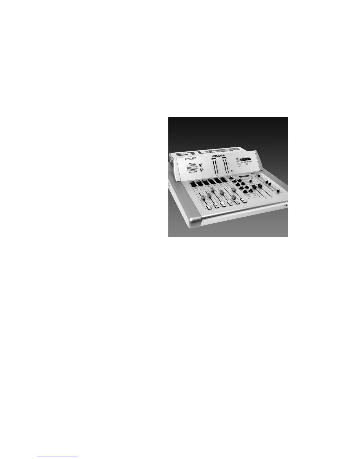
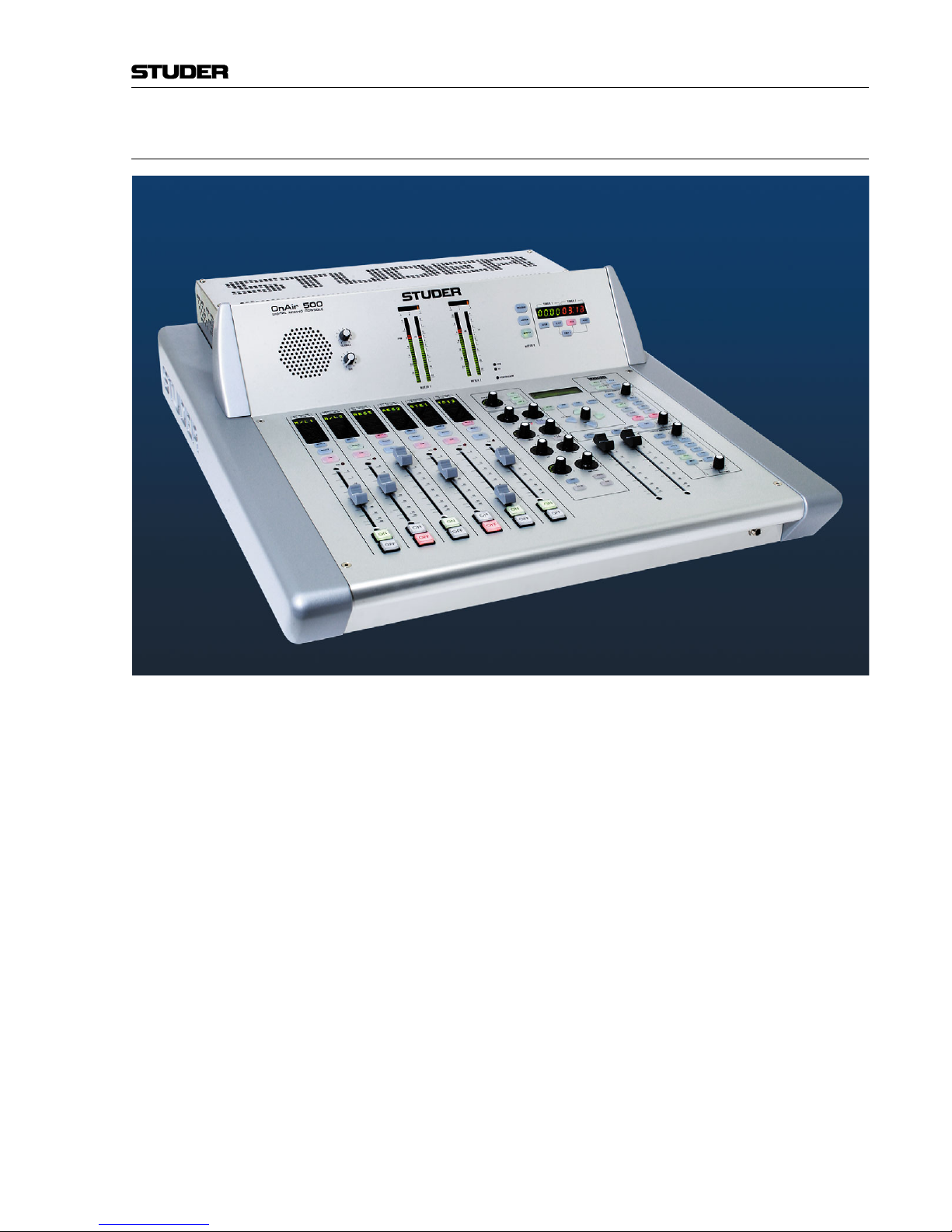
Studer OnAir 500
Digital Mixing Console
Operating Instructions
Page 2
Safety Information
I
A Safety Information
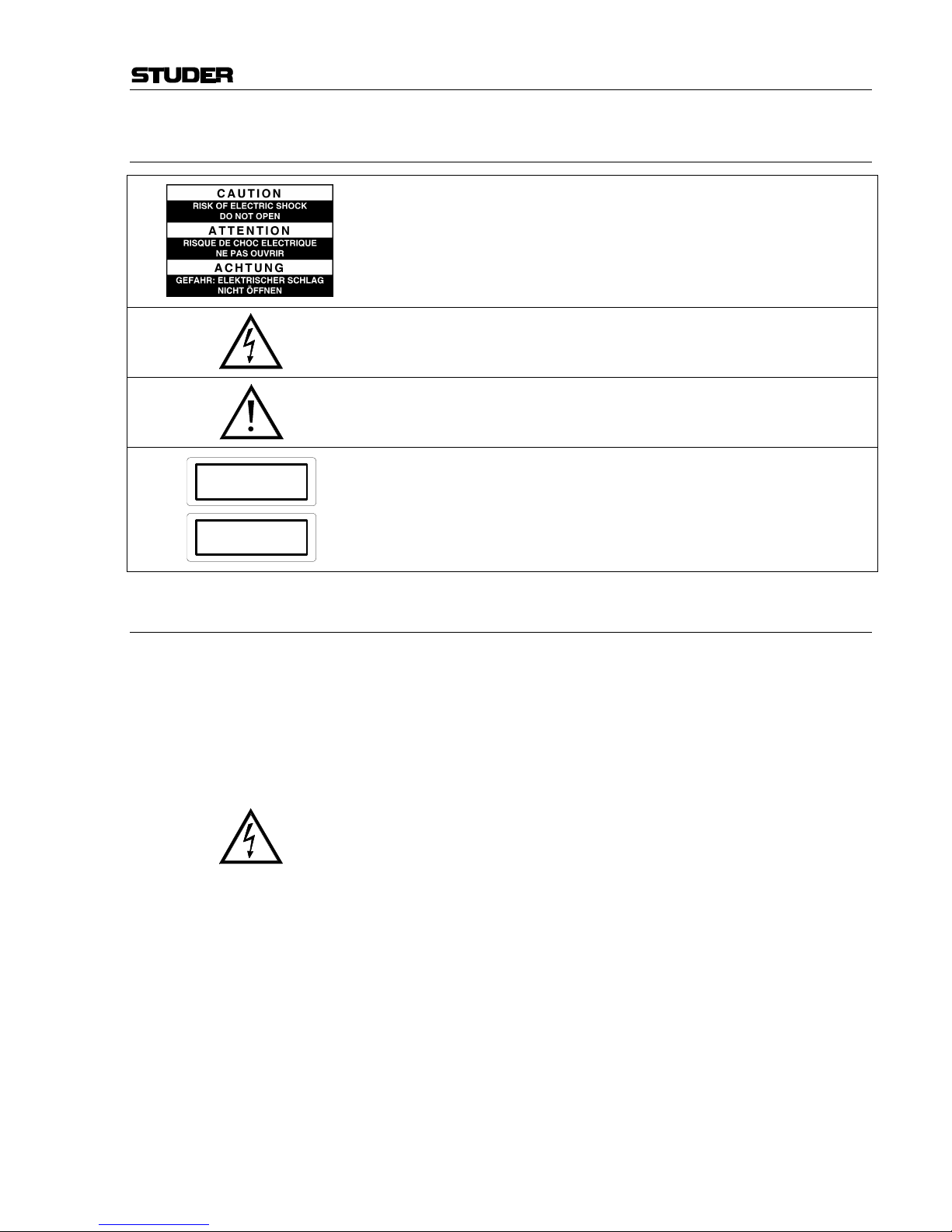
To reduce the risk of electric shock, do not remove covers. No userserviceable parts inside. Refer servicing to qualified service personnel
(i.e., persons having appropriate technical training and experience necessary to be aware of hazards to which they are exposed in performing a
repair action, and of measures to minimize the danger of themselves).
This symbol alerts the user to the presence of un-insulated dangerous
voltage within the equipment that may be of sufficient magnitude to constitute a risk of electric shock to a person.
This symbol alerts the user to important instructions for operating and
maintenance in this documentation.
Assemblies or sub-assemblies of this product can contain opto-electronic
devices. As long as these devices comply with Class I of laser or LED
products according to EN 60825-1:1994, they will not be expressly
marked on the product. If a special design should be covered by a higher
class of this standard, the device concerned will be marked directly on
the assembly or sub-assembly in accordance with the above standard.
A1 First Aid
In Case of Electric Shock: Separate the person as quickly as possible from the electric power
source:
• By switching off the equipment,
• By unplugging or disconnecting the mains cable, or
• By pushing the person away from the power source, using dry,
insulating material (such as wood or plastic).
• After having suffered an electric shock, always consult a doctor.
Warning! Do not touch the person or his clothing before the power is turned
off, otherwise you stand the risk of suffering an electric shock as
well!
If the Person is Unconscious: • Lay the person down
• Turn him to one side
• Check the pulse
• Reanimate the person if respiration is poor
• Call for a doctor immediately.
CLASS I
LASER PRODUCT
CLASS I
LED PRODUCT
Page 3

Installation/Maintenance/ESD
II
B General Installation Instructions
Please consider besides these general instructions also any product-specific
instructions in the “Installation” chapter of this manual.
B1 Unpacking
Check the equipment for any transport damage. If the unit is mechanically
damaged, if liquids have been spilled or if objects have fallen into the unit,
it must not be connected to the AC power outlet, or it must be immediately
disconnected by unplugging the power cable. Repair must only be per-
formed by trained personnel in accordance with the applicable regulations.
B2 Installation Site
Install the unit in a place where the following conditions are met:
• The temperature and the relative humidity of the environment must be
within the specified limits during operation of the unit. Relevant values
are the ones at the air inlets of the unit.
• Condensation must be avoided. If the unit is installed in a location with
large variation of ambient temperature (e.g. in an OB-van), appropriate
precautions must be taken before and after operation (for details on this
subject, refer to Appendix 1).
• Unobstructed air flow is essential for proper operation. Air vents of the
unit are a functional part of the design and must not be blocked in any
way during operation (e.g. by objects placed upon them, placement of
the unit on a soft surface, or installation of the unit within a rack or
piece of furniture).
• The unit must not be heated up by external sources of heat radiation
(sunlight, spot lights).
B3 Earthing and Power Supply
Earthing of units with mains supply (class I equipment) is performed via
the protective earth (PE) conductor integrated in the mains cable. Units
with battery operation (< 60 V, class III equipment) must be earthed separately.
Earthing the unit is one of the measures for protection against electrical
shock hazard (dangerous body currents). Hazardous voltage may not only
be caused by a defective power supply insulation, but may also be introduced by the connected audio or control cables.
If the unit is installed with one or several external connections, its earthing
must be provided during operation as well as while the unit is not operated.
If the earthing connection can be interrupted, for example, by unplugging
the mains plug of an external power supply unit, an additional, permanent
earthing connection must be installed using the provided earth terminal.
Avoid ground loops (hum loops) by keeping the loop surface as small as
possible (by consequently guiding the earth conductors in a narrow, parallel way), and reduce the noise current flowing through the loop by inserting
an additional impedance (common-mode choke).
Page 4
ESD/Repair
III
Class I Equipment (Mains Operation)
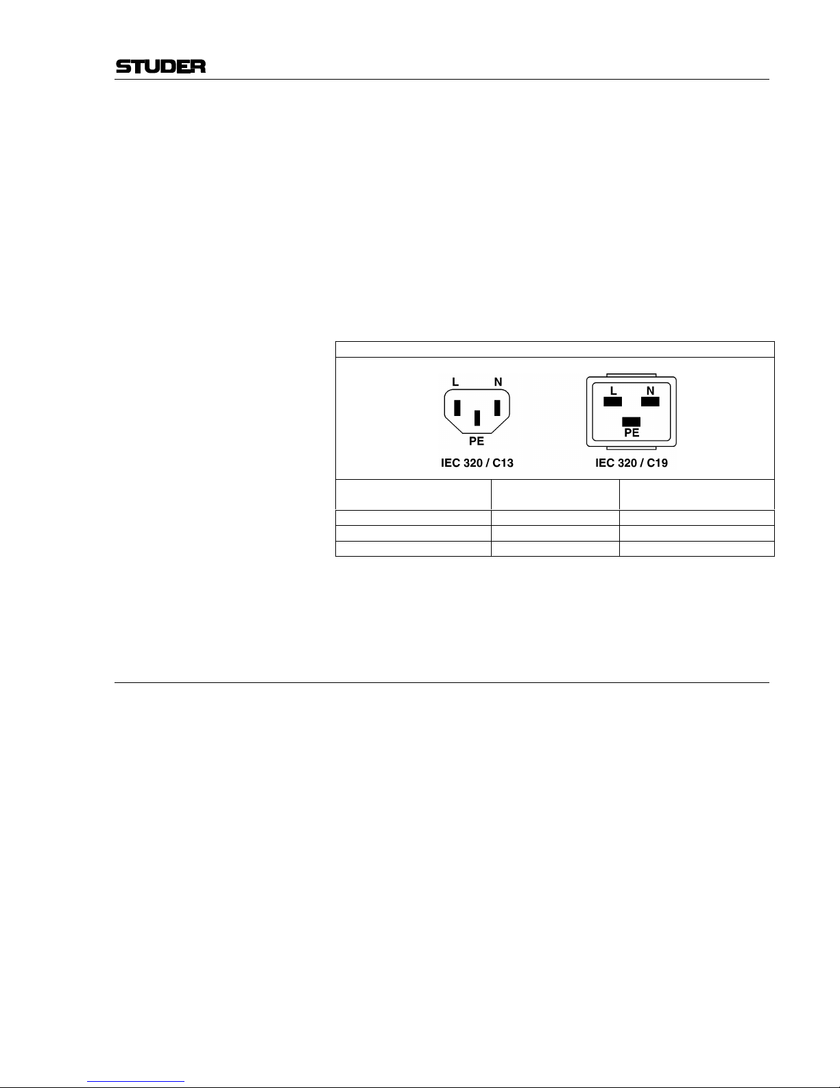
Should the equipment be delivered without a matching mains cable, the
latter has to be prepared by a trained person using the attached female plug
(IEC320/C13 or IEC320/C19) with respect to the applicable regulations in
your country.
Before connecting the equipment to the AC power outlet, check that the
local line voltage matches the equipment rating (voltage, frequency) within
the admissible tolerance. The equipment fuses must be rated in accordance
with the specifications on the equipment.
Equipment supplied with a 3-pole appliance inlet (protection conforming to
class I equipment) must be connected to a 3-pole AC power outlet so that
the equipment cabinet is connected to the protective earth.
For information on mains cable strain relief please refer to Appendix 2.
Female Plugs (IEC320), Front-Side View:
European Standard
(CENELEC)
North American Standard
(NAS)
Brown L (Live) Black
Blue N (Neutral) White
Green/Yellow PE (Protective Earth) Green (or Green/Yellow)
Class III Equipment (Battery Operation up to 60 VDC)
Equipment of this protection class must be earthed using the provided earth
terminal, if one or more external signals are connected to the unit (see explanation at the beginning of this paragraph).
B4 Electromagnetic Compatibility (EMC)
The unit conforms to the protection requirements relevant to electromagnetic phenomena that are listed in guidelines 89/336/EC and FCC, part 15.
• The electromagnetic interference generated by the unit is limited in such
a way that other equipment and systems can be operated normally.
• The unit is adequately protected against electromagnetic interference so
that it can operate properly.
The unit has been tested and conforms to the EMC standards of the specified electromagnetic environment, as listed in the following declaration.
The limits of these standards ensure protection of the environment and corresponding noise immunity of the equipment with appropriate probability.
However, a professional installation and integration within the system are
imperative prerequisites for operation without EMC problems.
For this purpose, the following measures must be followed:
• Install the equipment in accordance with the operating instructions. Use
the supplied accessories.
• In the system and in the vicinity where the equipment is installed, use
only components (systems, equipment) that also fulfill the EMC standards for the given environment.
• Use a system grounding concept that satisfies the safety requirements
(class I equipment must be connected with a protective ground conduc-
Page 5

Installation/Maintenance/ESD
IV
tor) and that also takes into consideration the EMC requirements. When
deciding between radial, surface, or combined grounding, the advantages and disadvantages should be carefully evaluated in each case.
• Use shielded cables where shielding is specified. The connection of the
shield to the corresponding connector terminal or housing should have a
large surface and be corrosion-proof. Please note that a cable shield
connected only single-ended can act as a transmitting or receiving antenna within the corresponding frequency range.
• Avoid ground loops or reduce their adverse effects by keeping the loop
surface as small as possible, and reduce the noise current flowing
through the loop by inserting an additional impedance (e.g. commonmode choke).
• Reduce electrostatic discharge (ESD) of persons by installing an appropriate floor covering (e.g. a carpet with permanent electrostatic filaments) and by keeping the relative humidity above 30%. Further measures (e.g. conducting floor) are usually unnecessary and only effective if
used together with corresponding personal equipment.
• When using equipment with touch-sensitive operator controls, please
take care that the surrounding building structure allows for sufficient
capacitive coupling of the operator. This coupling can be improved by
an additional, conducting surface in the operator’s area, connected to the
equipment housing (e.g. metal foil underneath the floor covering, carpet
with conductive backing).
C Maintenance
All air vents and openings for operating elements (faders, rotary knobs)
must be checked on a regular basis, and cleaned in case of dust accumulation. For cleaning, a soft paint-brush or a vacuum cleaner is recommended.
Cleaning the surfaces of the unit is performed with a soft, dry cloth or a
soft brush.
Persistent contamination can be treated with a cloth that is slightly humidified with a mild cleaning solution (soap-suds).
For cleaning display windows, commercially available computer/TV
screen cleaners are suited. Use only a slightly damp (never wet) cloth.
Never use any solvents for cleaning the exterior of the unit! Liquids must
never be sprayed or poured on directly!
For equipment-specific maintenance information please refer to the corresponding chapter in the Operating and Service Instructions manuals.
D Electrostatic Discharge during Maintenance and Repair
Caution: Observe the precautions for handling devices sensitive to electrostatic dis-
charge!
Many semiconductor components are sensitive to electrostatic discharge
(ESD). The life-span of assemblies containing such components can be
drastically reduced by improper handling during maintenance and repair
work. Please observe the following rules when handling ESD sensitive
components:
• ESD sensitive components should only be stored and transported in the
packing material specifically provided for this purpose.
• When performing a repair by replacing complete assemblies, the removed assembly must be sent back to the supplier in the same packing
Page 6

ESD/Repair
V
material in which the replacement assembly was shipped. If this should
not be the case, any claim for a possible refund will be null and void.
• Unpacked ESD sensitive components should only be handled in ESD
protected areas (EPA, e.g. area for field service, repair or service bench)
and only be touched by persons who wear a wristlet that is connected to
the ground potential of the repair or service bench by a series resistor.
The equipment to be repaired or serviced as well as all tools and electrically semi-conducting work, storage, and floor mats should also be connected to this ground potential.
• The terminals of ESD sensitive components must not come in uncontrolled contact with electrostatically chargeable (voltage puncture) or
metallic surfaces (discharge shock hazard).
• To prevent undefined transient stress of the components and possible
damage due to inadmissible voltages or compensation currents, electrical connections should only be established or separated when the
equipment is switched off and after any capacitor charges have decayed.
E Repair
Removal of housing parts, shields, etc. exposes energized parts. For this
reason the following precautions must be observed:
• Maintenance may only be performed by trained personnel in accordance
with the applicable regulations.
• The equipment must be switched off and disconnected from the AC
power outlet before any housing parts are removed.
• Even if the equipment is disconnected from the power outlet, parts with
hazardous charges (e.g. capacitors, picture tubes) must not be touched
until they have been properly discharged. Do not touch hot components
(power semiconductors, heat sinks, etc.) before they have cooled off.
• If maintenance is performed on a unit that is opened and switched on, no
un-insulated circuit components and metallic semiconductor housings
must be touched, neither with your bare hands nor with un-insulated
tools.
Certain components pose additional hazards:
• Explosion hazard from lithium batteries, electrolytic capacitors and
power semiconductors (watch the component’s polarity. Do not short
battery terminals. Replace batteries only by the same type).
• Implosion hazard from evacuated display units.
• Radiation hazard from laser units (non-ionizing), picture tubes (ionizing).
• Caustic effect of display units (LCD) and components containing liquid
electrolyte.
Such components should only be handled by trained personnel who are
properly protected (e.g. safety goggles, gloves).
Page 7
Repair/Disposal
VI
E1 SMD Components
Studer has no commercially available SMD components in stock for service purposes. For repair, the corresponding devices have to be purchased
locally. The specifications of special components can be found in the service manual.
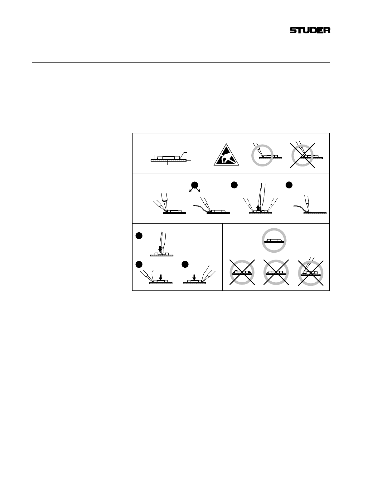
SMD components should only be replaced by skilled specialists using appropriate tools. No warranty claims will be accepted for circuit boards that
have been damaged. Proper and improper SMD soldering joints are illustrated below.
F Disposal
Disposal of Packing Materials The packing materials have been selected with environmental and disposal
issues in mind. All packing material can be recycled. Recycling packing
saves raw materials and reduces the volume of waste.
If you need to dispose of the transport packing materials, please try to use
recyclable means.
Disposal of Used Equipment Used equipment contains valuable raw materials as well as materials that
must be disposed of professionally. Please return your used equipment via
an authorized specialist dealer or via the public waste disposal system, ensuring any material that can be recycled is.
Please take care that your used equipment cannot be abused. To avoid
abuse, delete sensitive data from any data storage media. After having disconnected your used equipment from the mains supply, make sure that the
mains connector and the mains cable are made useless.
32
Dismounting
Mounting
Examples
Solder
SMD
Component
Copper
Track
Adhesive
Soldering Iron
Desoldering
Iron
Desolder
Wick
Heat and Remove Cleaning
Solder
Ø 0.5...0.8 mm
Heating Time < 3 s per Side
Soldering
Iron
Desolder
Wick
1
3
2
1
PCB
Page 8

Conformity
VII
G Declarations of Conformity
G1 Class A Equipment - FCC Notice
This equipment has been tested and found to comply with the limits for a
Class A digital device, pursuant to Part 15 of the FCC Rules. These limits
are designed to provide a reasonable protection against harmful interference when the equipment is operated in a commercial environment. This
equipment generates, uses, and can radiate radio frequency energy and, if
not installed and used in accordance with the instruction manual, may
cause harmful interference to radio communications. Operation of this
equipment in a residential area is likely to cause harmful interference, in
which case the user will be required to correct the interference at his own
expense.
Caution: Any changes or modifications not expressly approved by the manufacturer
could void the user's authority to operate the equipment. Also refer to relevant information in this manual.
G2 CE Declaration of Conformity
We,
Studer Professional Audio GmbH,
CH-8105 Regensdorf,
declare under our sole responsibility that the product
Studer OnAir 500, Digital Mixing Console
(starting with serial no. 1001)
to which this declaration relates, according to following regulations of EU
directives and amendments
• Low Voltage (LVD):
73/23/EEC + 93/68/EEC
• Electromagnetic Compatibility (EMC):
89/336/EEC + 92/31/EEC + 93/68/EEC
is in conformity with the following standards or normative documents:
• Safety:
EN 60950:2000 (Class I equipment)
• Safety of laser products:
EN 60825-1:1994 + A11 + A2, EN60825-2:2000
• EMC:
EN 55103-1/-2:1996, electromagnetic environments E2 and E4.
Regensdorf, July 21, 2003
B. Hochstrasser, President P. Fiala, Manager QA
Page 9

Appendix
VIII
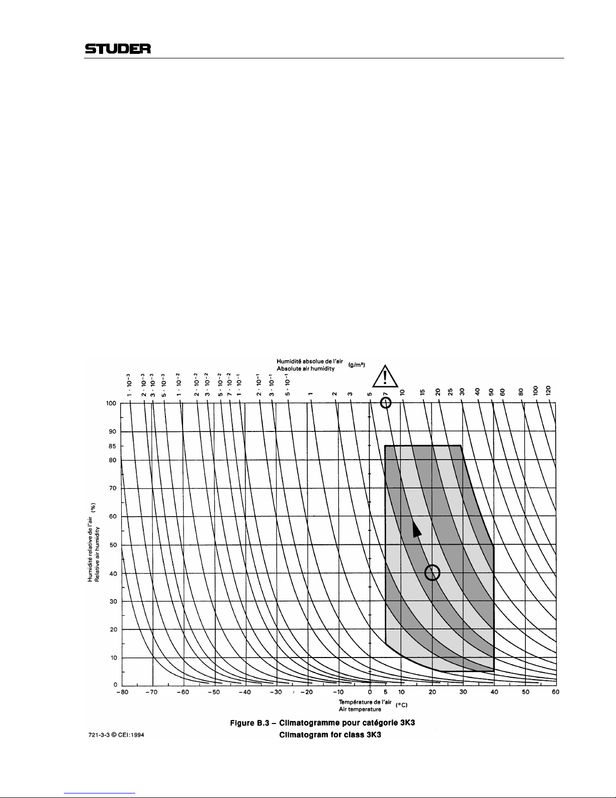
Appendix 1: Air Temperature and Humidity
General
Normal operation of the unit or system is warranted under the following
ambient conditions defined by EN 60721-3-3, set IE32, value 3K3.
This standard consists of an extensive catalogue of parameters, the most
important of which are: ambient temperature +5...+40 °C, relative humidity
5...85% (i.e., no formation of condensation or ice); absolute humidity
1...25 g/m³; rate of temperature change < 0.5 °C/min. These parameters are
dealt with in the following paragraphs.
Under these conditions the unit or system starts and works without any
problem. Beyond these specifications, possible problems are described in
the following paragraphs.
Ambient Temperature
Units and systems by Studer are generally designed for an ambient temperature range (i.e. temperature of the incoming air) of +5...+40 °C. When
rack mounting the units, the intended air flow and herewith adequate cooling must be provided. The following facts must be considered:
• The admissible ambient temperature range for operation of the semiconductor components is 0 °C to +70 °C (commercial temperature range
for operation).
• The air flow through the installation must provide that the outgoing air
is always cooler than 70 °C.
• Average heat increase of the cooling air shall be about 20 K, allowing
for an additional maximum 10 K increase at the hot components.
• In order to dissipate 1 kW with this admissible average heat increase, an
air flow of 2.65 m³/min is required.
Example: A rack dissipating P = 800 W requires an air flow of 0.8 * 2.65 m³/min
which corresponds to 2.12 m³/min.
• If the cooling function of the installation must be monitored (e.g. for fan
failure or illumination with spot lamps), the outgoing air temperature
must be measured directly above the modules at several places within
the rack. The trigger temperature of the sensors should be 65 to 70 °C.
Frost and Dew
The unsealed system parts (connector areas and semiconductor pins) allow
for a minute formation of ice or frost. However, formation of dew visible
with the naked eye will already lead to malfunctions. In practice, reliable
operation can be expected in a temperature range above –15 °C, if the following general rule is considered for putting the cold system into operation:
If the air within the system is cooled down, the relative humidity rises. If it
reaches 100%, condensation will arise, usually in the boundary layer between the air and a cooler surface, together with formation of ice or dew at
sensitive areas of the system (contacts, IC pins, etc.). Once internal condensation occurs, trouble-free operation cannot be guaranteed, independent
of temperature.
Before putting into operation, the system must be checked for internal formation of condensation or ice. Only with a minute formation of ice, direct
Page 10
Appendix
IX
evaporation (sublimation) may be expected; otherwise the system must be
heated and dried while switched off.
A system without visible internal formation of ice or condensation should
be heated up with its own heat dissipation, as homogeneously (and subsequently as slow) as possible; the ambient temperature should then always
be lower than the one of the outgoing air.
If it is absolutely necessary to operate the cold system immediately within
warm ambient air, this air must be dehydrated. In such a case, the absolute
humidity must be so low that the relative humidity, related to the coldest
system surface, always remains below 100%.
Ensure that the enclosed air is as dry as possible when powering off (i.e.
before switching off in winter, aerate the room with cold, dry air, and remove humid objects as clothes from the room).
These relationships are visible from the following climatogram. For a controlled procedure, thermometer and hygrometer as well as a thermometer
within the system will be required.
Example 1: An OB-van having an internal temperature of 20 °C and relative humidity
of 40% is switched off in the evening. If temperature falls below +5 °C,
dew or ice will be forming.
Example 2: An OB-van is heated up in the morning with air of 20 °C and a relative
humidity of 40%. On all parts being cooler than +5 °C, dew or ice will be
forming.
Page 11
Appendix
X
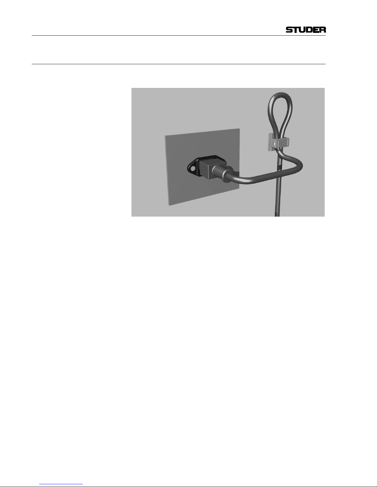
Appendix 2: Mains Connector Strain Relief
For anchoring connectors without a mechanical lock (e.g. IEC mains connectors), we recommend the following arrangement:
Procedure: The cable clamp shipped with your unit is auto-adhesive. For mounting
please follow the rules below:
• The surface to be adhered to must be clean, dry, and free from grease,
oil, or other contaminants. Recommended application temperature range
is +20...+40 °C.
• Remove the plastic protective backing from the rear side of the clamp
and apply it firmly to the surface at the desired position. Allow as much
time as possible for curing. The bond continues to develop for as long as
24 hours.
• For improved stability, the clamp should be fixed with a screw. For this
purpose, a self-tapping screw and an M4 bolt and nut are included.
• Place the cable into the clamp as shown in the illustration above and
firmly press down the internal top cover until the cable is fixed.
Page 12

Appendix
XI
Appendix 3: Software License
Use of the software is subject to the Studer Professional Audio Software
License Agreement set forth below. Using the software indicates your acceptance of this license agreement. If you do not accept these license terms,
you are not authorized to use this software.
Under the condition and within the scope of the following Terms and Conditions, Studer Professional Audio GmbH (hereinafter “Studer”) grants the
right to use programs developed by Studer as well as those of third parties
which have been installed by Studer on or within its products. References
to the license programs shall be references to the newest release of a license program installed at the Customer’s site.
Programs Covered by the Agreement
License Programs of Studer The following Terms and Conditions grant the right to use all programs of
Studer that are part of the System and/or its options at the time of its delivery to the Customer, as well as the installation software on the original data
disk and the accompanying documentation (“License Material”). In this
Agreement the word “Programs” shall have the meaning of programs and
data written in machine code.
Using the software indicates your acceptance of this license agreement. If
you do not accept these license terms, you are not authorized to use this
software.
Programs of Third Parties Programs of third parties are all programs which constitute part of the
System and/or its options at the time of delivery to the Customer but have
not been developed by Studer. The following conditions are applicable to
programs of third parties:
• The right to use third parties’ programs is governed by the License
Agreement attached hereto (if applicable), which is an integral part of
this Agreement. The Customer shall sign any and all License Agreements for all further programs of third parties installed on the system.
The Customer shall be deemed to have received all License Agreements
upon delivery of the system and/or its options.
• Studer shall accept no responsibility or liability for, and gives no warranties (express or implied) as to the programs of third parties. The
Customer waives any and all claims versus Studer for any consequential
damages, which might occur due to defects of these programs.
Right of Use
Principle Studer grants the Customer the non-exclusive right to use the License Ma-
terial in one copy on the system and/or its options as laid down by the
Sales Agreement concluded between the parties and all Terms and Conditions which shall be deemed to form and be read and construed as part of
the Sales Agreement. This right is assignable according to the “Assignability” paragraph hereinafter.
Customized Configurations The Customer is not entitled to alter or develop further the License Mate-
rial except within the expressly permitted configuration possibilities given
by the software installed on the system or elsewhere. All altered programs,
including but not limited to the products altered within the permitted configuration possibilities, are covered by this License Agreement.
Page 13

Appendix
XII
Reverse Engineering Reverse engineering is only permitted with the express consent of Studer.
The consent of Studer can be obtained but is not limited to the case in
which the interface-software can not be provided by Studer. In any case
Studer has to be informed immediately upon complete or partial reverse
engineering.
Copying the License Material The Customer is entitled to make one copy of all or parts of the License
Material as is necessary for the use according to this Agreement, namely
for backup purposes. The Customer shall apply the copyright of Studer
found on the License Material onto all copies made by him. Records shall
be kept by the Customer regarding the amount of copies made and their
place of keeping. The responsibility for the original program and all copies
made lies with the Customer. Studer is entitled to check these records on
first request. Copies not needed anymore have to be destroyed immediately.
Disclosure of License Material The License Material is a business secret of Studer. The Customer shall not
hand out or in any way give access to parts or the complete License Material to third parties nor to publish any part of the License Material without
prior written consent of Studer. The Customer shall protect the License
Material and any copies made according to the paragraph above by appropriate defense measures against unauthorized access. This obligation of
non-disclosure is a perpetual obligation.
Third parties are entitled to have access to the License Material if they use
the License Material at the Customer’s site in compliance with this Agreement.
Under no circumstance are third parties entitled to have access to the installation software on the original data media. The Customer shall safeguard the original data media accordingly.
Assignability The rights granted to the Customer according to this License Agreement
shall only be assignable to a third party together with the transfer of the
system and/or its options and after the prior written consent of Studer.
Rights to License Material
With the exception of the right of use granted by this License Agreement
all proprietary rights to the License Material, especially the ownership and
the intellectual property rights (such as but not limited to patents and copyright) remain with Studer even if alterations, customized changes or
amendments have been made to the License Material.
Studer’s proprietary rights are acknowledged by the Customer. The Customer shall undertake no infringements and make no claims of any patent,
registered design, copyright, trade mark or trade name, or other intellectual
property right.
Warranty, Disclaimer, and Liability
For all issues not covered herewithin, refer to the “General Terms and
Conditions of Sales and Delivery” being part of the sales contract.
Page 14

OnAir 500 Digital Mixing Console
Contents 0-1Date printed:
30.07.04
CONTENTS
1 Introduction ....................................................................................................................................................................1-1
1.1 Key Features ............................................................................................................................................................. 1-2
1.2 Feature Overview .....................................................................................................................................................1-3
1.3 Studer OnAir 500 Block Diagram ............................................................................................................................1-4
2 General ............................................................................................................................................................................2-1
2.1 Utilization for the Purpose Intended ........................................................................................................................2-1
2.2 First Steps .................................................................................................................................................................2-1
2.2.1 Unpacking and Inspection .................................................................................................................................2-1
2.2.2 Installation .........................................................................................................................................................2-1
2.2.3 Adjustments, Repair ..........................................................................................................................................2-2
2.3 Technical Specifications ...........................................................................................................................................2-3
2.3.1 Typical Values .................................................................................................................................................... 2-3
2.3.2 Mechanical Dimensions ....................................................................................................................................2-4
3 Operating Elements........................................................................................................................................................3-1
3.1 Power Switch ............................................................................................................................................................3-1
3.2 Channel Strip ............................................................................................................................................................3-3
3.3 Edit Strip...................................................................................................................................................................3-5
3.4 Monitoring Section ...................................................................................................................................................3-9
3.5 Master Section ........................................................................................................................................................3-11
3.6 Meter Bridge ..........................................................................................................................................................3-14
4 The Menu Pages .............................................................................................................................................................4-1
4.1 Analog Inputs ...........................................................................................................................................................4-2
4.2 Assign Channel .........................................................................................................................................................4-4
4.3 Auto Muting ............................................................................................................................................................. 4-6
4.4 Channel Phases ......................................................................................................................................................... 4-7
4.5 Clock Source ............................................................................................................................................................4-8
4.6 Digital Outputs .........................................................................................................................................................4-9
4.7 Digital Out Adv. (Advanced) .................................................................................................................................4-10
4.8 Display Settings ......................................................................................................................................................4-12
4.9 External IP (Input) Gain ......................................................................................................................................... 4-12
4.10 Guest Headphones Level ........................................................................................................................................4-13
4.11 HPF Frequency ....................................................................................................................................................... 4-13
4.12 Input Naming ..........................................................................................................................................................4-14
4.13 Line/CF Outputs .....................................................................................................................................................4-14
4.14 Lockout PIN ...........................................................................................................................................................4-17
4.15 Lockout Setup .........................................................................................................................................................4-18
4.16 Lockout Status ........................................................................................................................................................4-19
4.17 Machine Starts ........................................................................................................................................................4-20
4.18 Master Faders .........................................................................................................................................................4-22
4.19 MIDI Backup ..........................................................................................................................................................4-22
4.20 Mono Output ..........................................................................................................................................................4-24
4.21 CUE Autocancel ..................................................................................................................................................... 4-24
Page 15

OnAir 500 Digital Mixing Console
0-2 Contents Date printed:
30.07.04
4.22 RCS Channel Sel ....................................................................................................................................................4-25
4.23 RCS Setup ..............................................................................................................................................................4-25
4.24 Remote Inputs .........................................................................................................................................................4-26
4.25 Software Version ....................................................................................................................................................4-27
4.26 System ....................................................................................................................................................................4-27
4.27 Talkback Assign .....................................................................................................................................................4-28
4.28 TDIF Outputs .........................................................................................................................................................4-29
4.29 TDIF Out Adv.........................................................................................................................................................4-30
4.30 2nd Meter Source ...................................................................................................................................................4-31
5 Talkback ..........................................................................................................................................................................5-1
5.1 Scenario 1 - Presenter in Control Room (Talkback Swap Off) ............................................................................... 5-1
5.2 Scenario 2 - Presenter in Studio (Talkback Swap On) ............................................................................................. 5-2
6 Dynamics .........................................................................................................................................................................6-1
6.1 Gate ..........................................................................................................................................................................6-1
6.2 Compressor ...............................................................................................................................................................6-2
6.3 Limiter ......................................................................................................................................................................6-3
6.4 Compressor + Gate / Limiter + Gate ........................................................................................................................6-3
6.5 Assigning the Dynamics Processors.........................................................................................................................6-3
6.6 Adjusting Dynamics Processor Settings .................................................................................................................. 6-4
6.7 Dynamics Presets .....................................................................................................................................................6-5
6.7.1 Storing and Naming a Dynamics Preset ............................................................................................................ 6-5
6.7.2 Recalling a Dynamics Preset .............................................................................................................................6-5
6.7.3 Deleting a Dynamics Preset...............................................................................................................................6-6
7 Lexicon™ Effects ...........................................................................................................................................................7-1
7.1 Selecting an Effect ....................................................................................................................................................7-1
7.2 Applying the Effect to a Signal ................................................................................................................................7-2
7.3 Editing, Storing and Renaming an Effect .................................................................................................................7-2
7.4 Deleting an Effect .....................................................................................................................................................7-3
8 Presets ..............................................................................................................................................................................8-1
8.1 Storing a Snapshot Preset .........................................................................................................................................8-2
8.2 Renaming a Snapshot Preset ....................................................................................................................................8-2
8.3 Recalling a Snapshot Preset .....................................................................................................................................8-3
8.4 Deleting a Snapshot Preset ....................................................................................................................................... 8-4
8.5 Recalling the Factory Default Preset........................................................................................................................8-4
9 Timer Operation ............................................................................................................................................................. 9-1
9.1 Manual Operation .....................................................................................................................................................9-1
9.2 Automatic Operation ................................................................................................................................................9-1
Page 16

OnAir 500 Digital Mixing Console
Contents 0-3Date printed:
30.07.04
10 Automation Operation ................................................................................................................................................ 10-1
10.1 OnAir 500 and Studer DigiMedia ..........................................................................................................................10-1
10.1.1 Control Connections and Setup .......................................................................................................................10-1
10.1.2 Audio Connections ..........................................................................................................................................10-2
10.1.3 Operation .........................................................................................................................................................10-2
10.2 OnAir 500 and RCS System ...................................................................................................................................10-3
10.2.1 Connections and Setup ....................................................................................................................................10-3
10.2.2 Operation .........................................................................................................................................................10-4
11 Software Update / Re-Initializing ............................................................................................................................... 11-1
11.1 SW Update ............................................................................................................................................................. 11-1
11.1.1 Preparing the Hardware ................................................................................................................................... 11-1
11.1.2 Preparing the PC ..............................................................................................................................................11-2
11.1.3 Transferring the Software ................................................................................................................................ 11-3
11.2 Re-Initializing the OnAir 500 ................................................................................................................................11-5
11.2.1 Total Reset of the OnAir 500 ..........................................................................................................................11-5
11.2.2 Effects/Dynamics Presets Reset ......................................................................................................................11-5
11.2.3 Snapshot Presets Reset .................................................................................................................................... 11-6
11.2.4 Restoring the Factory Default Preset .............................................................................................................. 11-6
12 Connectors, Test Hookup ........................................................................................................................................... 12-1
12.1 Connector Panel .....................................................................................................................................................12-1
12.1.1 Connector Set ..................................................................................................................................................12-2
12.2 Connector Pin Assignments....................................................................................................................................12-2
12.2.1 Audio Inputs ....................................................................................................................................................12-2
12.2.2 Audio Outputs ..................................................................................................................................................12-2
12.2.3 Miscellaneous Audio Inputs/Outputs ..............................................................................................................12-3
12.2.4 Control Inputs/Outputs ....................................................................................................................................12-4
12.2.5 External 24 VDC Supply ...................................................................................................................................12-6
12.3 Test Hookup ...........................................................................................................................................................12-7
12.3.1 Before you Start ...............................................................................................................................................12-7
12.3.2 Audio Test Hookup..........................................................................................................................................12-7
12.3.3 Input Assignment .............................................................................................................................................12-8
12.3.4 Input Naming ...................................................................................................................................................12-8
12.3.5 Connecting an Input .........................................................................................................................................12-9
12.3.6 Channel Output Assignment ............................................................................................................................12-9
12.3.7 Add some EQ to the Signal .......................................................................................................................... 12-10
12.3.8 Add some Reverb to the Signal .................................................................................................................... 12-10
12.3.9 Return to the Normal Configuration .............................................................................................................12-11
13 Index ............................................................................................................................................................................. 13-1
Page 17

OnAir 500 Digital Mixing Console
0-4 Contents Date printed:
30.07.04
Page 18
OnAir 500 Digital Mixing Console
Introduction 1-1
Date printed:
30.07.04
1 INTRODUCTION
The Studer OnAir 500 is designed first and foremost as a broadcast radio
console, which can simply drop in to any existing setup with a minimum of
fuss. This might be as a replacement for older analog equipment, or integration into a totally digital environment. The instantly familiar “analog” control style of the Studer OnAir 500 ensures that users do not have to fight with
the technology in order to start using the powerful features on offer. The
added benefits of automation to the professional radio presenter are obvious
– simple single-key recall of a complete console state with effects, routing
and EQ all configured, according to the user’s preferences. Whether in a
studio or in an outside broadcast vehicle, the Studer OnAir 500 will offer the
user repeatable, detailed control over a powerful feature set, in a simple and
efficient manner.
All of this control would have been little use without the intuitive interface
incorporating the edit strip, which allows fast access to all audio parameters
on the console when used in conjunction with the EDIT key present on each
channel. The “Tap and Adjust” functionality of the Studer OnAir 500 provides even the first-time operator with a familiar channel strip and a meter
bridge equipped with bar graph meters.
Page 19

OnAir 500 Digital Mixing Console
1-2 Introduction Date printed:
30.07.04
Each channel has full access to the edit strip, which offers three-band EQ
with semi-parametric midrange equalization, variable high-pass filter and
two auxiliary sends, a digital trim control with a range of ±12 dB, and a pan/
balance control. Every channel has an assignable stereo dynamics processor
offering a choice of compression, limiting and gating facilities.
The on-board Lexicon™ effects processor can be accessed from any channel
by configuring either the AUX 1 or AUX 2 send to operate as an effects send.
Immediacy is critical in the broadcast environment and so it was important
to have controls on each channel, like input 2 switching. Also included are
advanced but simple-to-use functions, like how the channel ON keys or fader
movements can trigger remote equipment, and how the PFL key can activate
talkback to cleanfeeds if required. Comprehensive talkback facilities and
compatibility with existing systems ensure that the user is never out of touch
even during the most complex of outside broadcast links.
The built-in MIDI ports allow full backup and restore of console presets via
MIDI system-exclusive data transfers.
1.1 Key Features
The Studer OnAir 500 offers the following features:
• Six assignable 100 mm faders
• Meter bridge with choice of VU or PPM metering
• Built-in cue/reverse talkback loudspeaker
• Two flexible timers for logging and scheduling
• Flexible routing of inputs
• Easy to use “analog” style user interface
• External monitor muting and equipment control via assignable contact switch
outputs
• External control inputs for cough muting and enabling reverse talkback
• Independently assignable line/talkback/cleanfeed outputs with “mix-minus”
facility
• Built-in LexiconTM digital effects processor with 128 available FX presets
• Assignable channel dynamics
• 128 desk presets for storage and recall of digital console parameters
• Backup and restore of snapshot, dynamic and FX presets via MIDI
• Software upgrades via built-in RS232 port
• Backlit LCD screen for parameter editing, global setup and configuration
• Integrated, auto-ranging power supply unit (100...240 VAC, 50...60 Hz)
• Input connector for 24 VDC supply, can be used for first-level PSU redundancy.
Page 20

OnAir 500 Digital Mixing Console
Introduction 1-3
Date printed:
30.07.04
1.2 Feature Overview
Analog Inputs The Studer OnAir 500 offers four assignable mic/line inputs, using digitally
controlled mic pre-amps. Two mic/line Inputs have an analog insert point
using a stereo jack plug, and all have a gain range from 0 to +60 dB, with
switchable 48 V phantom power. Two stereo inputs are also available with a
gain range from 0 to +18 dB. For monitoring purposes, there are four external stereo inputs accessible via a 37-pin D-type connector, with a gain range
from 0 to +18 dB. All of the above inputs are electronically balanced and
feature 24 bit, 128 × oversampling A/D converters.
A further eight analog inputs can be achieved by connecting an external mic/
line input interface box to the TDIF port found on the rear of the Studer
OnAir 500.
Analog Outputs The Studer OnAir 500 offers an array of analog outputs. There are electroni-
cally balanced XLR outputs for the PROG and AUD mix buses, and unbalanced outputs for control room and studio monitors. Outputs for guest, studio, and control room headphones are supplied, with a duplicate control room
headphone socket located at the front.
Outputs for AUX buses 1 and 2, line/clean-feed buses 1 and 2, stereo PFL,
mono PFL and cue speaker are located on the 37 pin D-type connector.
A further eight analog outputs can be achieved by connecting an external
analog output interface box to the TDIF port found on the rear of the Studer
OnAir 500.
Digital Inputs Four dedicated AES/EBU inputs and one S/PDIF input for connecting CD,
MiniDisc and DAT units are provided on the rear of the Studer OnAir 500.
Additional digital inputs are accessed by an eight-channel TDIF connector.
With the exception of the TDIF inputs, all other digital inputs are equipped
with sample rate converters, simplifying the setup and eliminating the need
for all devices in the system to share a common wordclock. All digital inputs
can be routed freely to any channel in exactly the same way as the analog
inputs, and therefore have the same access to the edit strip (there are, however, limitations regarding the routing of the S/PDIF input - see chapter 4.2
for details).
A further four AES/EBU inputs (four stereo or eight mono) can be achieved
by connecting an AES/EBU input interface box to the TDIF port.
Digital Outputs There are two AES/EBU digital outputs provided on male XLR connectors,
and one S/PDIF output via an RCA/Cinch connector. The TDIF connector
also provides eight additional digital outputs that can be configured to output a variety of mono or stereo sources.
A further four AES/EBU outputs (four stereo or eight mono) can be achieved
by connecting an AES/EBU output interface box to the TDIF port.
Meters The Studer OnAir 500 has two stereo bargraph meters with a correlation
indicator above each of them. On the METER 1, three easily selected modes
show either the PROG or AUD output buses or the control room selection;
for METER 2, the same sources are menu-selectable. Metering can be specified at the time of ordering with either VU or PPM characteristics.
(continued on page 1-6)
Page 21
OnAir 500 Digital Mixing Console
1-4 Introduction Date printed:
30.07.04
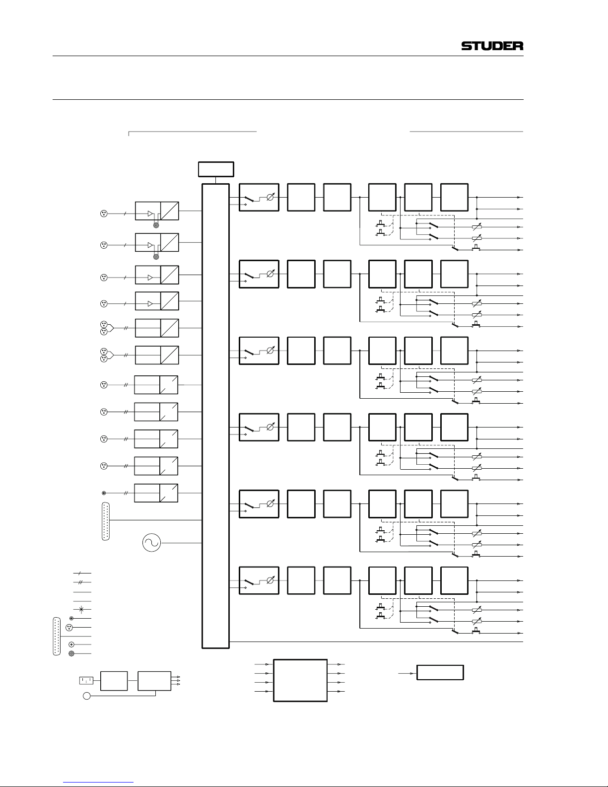
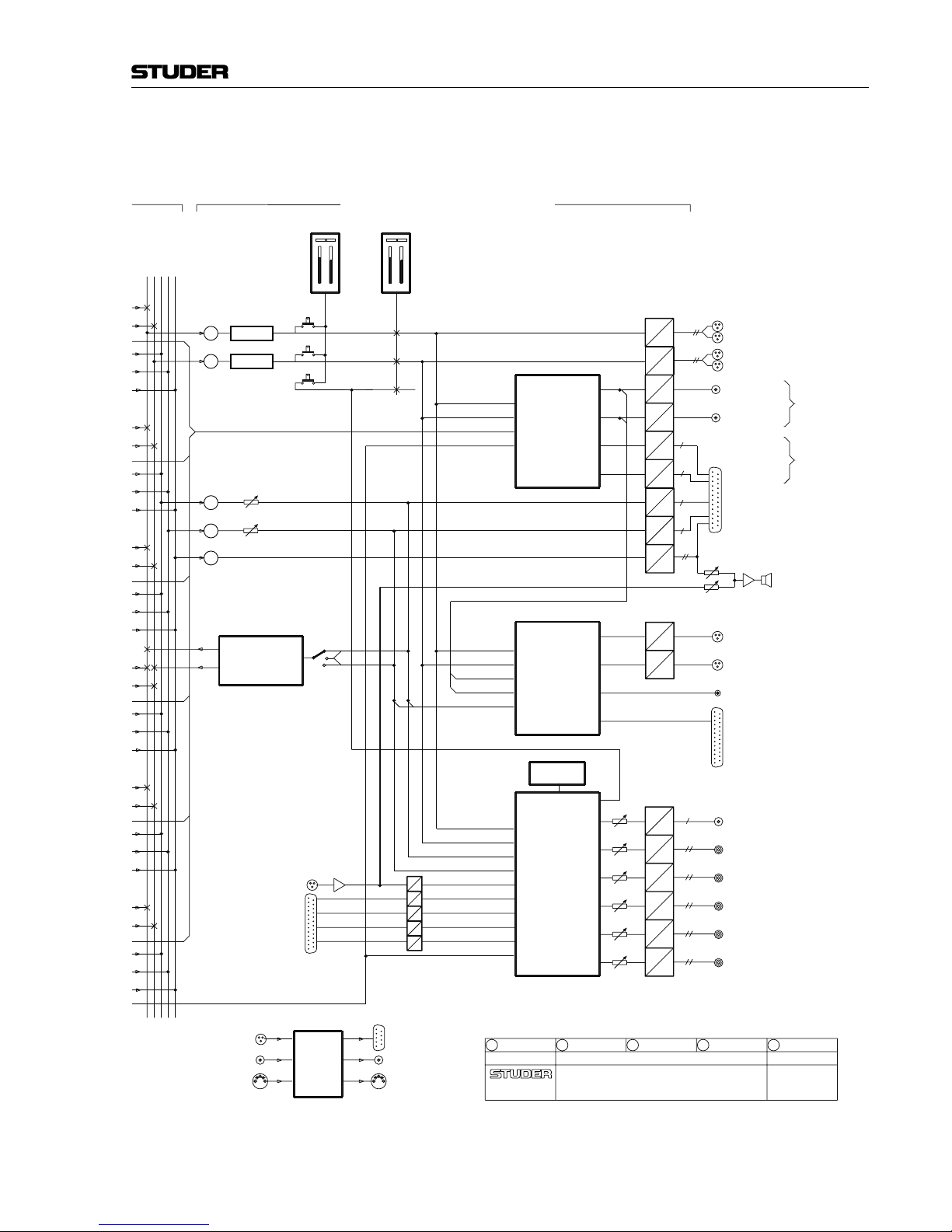
1.3 Studer OnAir 500 Block Diagram
A
PRE 1 A
D
D
PRE 2
PRE 3
D
A
A
D
MIC/LINE 1
MIC/LINE 2
D
D
DYN
EQ
FADER
AUX2
AUX1
STEREO IN 1
HL IN 1
a
a
a
a
AES IN 1d
SFC
AUX 1
AUX 2
CUE
AES 1
INSERT
MONO
STEREO
ANALOG SIGNAL
DIGITAL SIGNAL (AES/EBU)
CONFIG. SELECTION
d
a
PF
AF
XLR CONNECTOR
D-TYPE CONNECTOR
Σ AUDITION
Σ PROGRAM
TRS JACK SOCKET, STEREO, UNBAL
ON
CH
MIC/LINE 3
MIC/LINE 4
a
D
PRE 4 A
STEREO IN 2
aDHL IN 2 A
AES 2
dDAES IN 2
D
SFC
AES 4
d
AES 3
d
SFC
D
AES IN 4
D
D
AES IN 3
D
SFC
S/PDIF
d
SFC
D
S/PDIF IN
D
TDIF IN
1
8
INP SEL
HPF PAN/
BAL
GAIN
AF
PF
DIR OUT
ON
OFF
AF
PF
AUX 2
AUX 2
CUE
INP SEL GAIN
DYN
HPF
EQ BAL
AF
PF
FADER
AUX 1
PAN/
DIR OUT
AUX 1
Σ AUDITION
Σ PROGRAM
AF
PF
AUX 2
AUX 2
CUE
INP SEL GAIN
DYN
HPF
EQ BAL
AF
PF
FADER
AUX 1
PAN/
DIR OUT
AUX 1
Σ AUDITION
Σ PROGRAM
INP SEL GAIN
DYN
HPF
EQ BAL
PF
AF
PF
AF
FADER
AUX 2
AUX 1
AUX 2
CUE
AUX 1
DIR OUT
PAN/
Σ PROGRAM
Σ AUDITION
AF
PF
AUX 2
AUX 2
CUE
INP SEL GAIN
DYN
HPF
EQ BAL
AF
PF
FADER
AUX 1
PAN/
DIR OUT
AUX 1
Σ AUDITION
Σ PROGRAM
INP SEL GAIN
DYN
HPF
EQ BAL
PF
AF
PF
AF
FADER
AUX 2
AUX 1
AUX 2
CUE
AUX 1
DIR OUT
PAN/
Σ PROGRAM
Σ AUDITION
CINCH/RCA CONNECTOR
TRS JACK SOCKET, MONO, BAL
TALKBACK
INSERT
CONFIG. BY
LCD SCREEN
POWER
SUPPLY
MAINS
24 VDC
POWER
CONVERTER
FADER START 1...6
INPUT 1/2 LOGIC
EXT. REV TB SWITCH
EXT. COUGH SWITCH A/B
RELAY CONTACTS 1...12
TIMER CONTROL 1/2
REV TB ENABLE
A/B COUGH
OFF
ON
CH
ON
ON
OFF
CH
ON
ON
OFF
CH
ON
ON
OFF
CH
ON
ON
OFF
CH
ON
1 kHz GEN
INPUT/FADER CHANNELSINPUTS
INPUT ROUTER
LOGIC
CONTROL
TIMERS 1 & 2
Page 22
OnAir 500 Digital Mixing Console
Introduction 1-5
Date printed:
30.07.04
17.06.03/STI
OA500_V1.0
ON AIR 500 V1.0
AUDIO BLOCK DIAGRAM
REGENSDORF
SWITZERLAND
0
AUX 1 MASTER
AUX 2 MASTER
D
A
DAa
a
a
CUE/TB
AUX2
AUX1
METER 2
a
METER 1
D
A
Σ AUDITION
Σ PROGRAM A
Σ FADER
Σ FADER
+
+
PROGRAM
AUDITION
+
+
A
D
DAa
+
CUE
L
EXT IN 2
R
EXT IN 1
EXT IN 3
EXT IN 4
R
L
R
L
R
L
D
A
A
D
A
A
D
D
REV TB MIC IN
D
A
D
A
A
D
A
D
A
D
LINE OUT/
CLEANFEED 3
CLEANFEED 4
LINE OUT/
STEREO
LINKABLE
a
a
CLEANFEED 2
LINE OUT/
CLEANFEED 1
LINE OUT/
STEREO
LINKABLE
DIR OUT
AUD
PGM
INT TB
C/FEED 1/2
PGM
AUD
D
AES
AES
D
d
d
1
8
TDIF OUT
AES 1 OUT
AES 2 OUT
S/PDIF OUT
d
D
a
A
A
D
A
a
D
D
A
D
A
A
D
MONO MIX OUT
CR OUT
CR PHONES OUT
a
STUDIO OUT
a
STUDIO PHONES OUT
a
GUEST PHONES OUT
a
C/FEED 3/4
AUX 1/2
MONITOR
REV TB
AUX 2
AUX 1
AUD
PGM
INT TB
EXT 4
EXT 3
EXT 1
EXT 2
CONFIG. BY
LCD SCREEN
AUX 1/2
AUX 1
AUX 2
AES SYNCIN
MIDI IN
WORDCLOCK
RS232
MIDI OUT
WORDCLOCK
MAIN OUTPUTS
MASTER AND MONITORING
LINE OUTPUT
ROUTER
MIX MINUS
GENERATOR
ROUTER
OUTPUT
DIGITAL
MONITOR
&
SECTION
SOURCE
SELECT
/
LEXICON
FX
CPU
Page 23

OnAir 500 Digital Mixing Console
1-6 Introduction Date printed:
30.07.04
(cont.) Faders The 100 mm long-throw faders found on the Studer OnAir 500 work just as
you would expect on an analog console. The top end of the fader is calibrated
at 0 dB (unity gain). The master faders can be bypassed via the setup menu
so that both the PROG and AUD bus outputs are fixed at unity gain.
Edit Strip The edit strip places the main controls found on a conventional analog chan-
nel strip in one central, easy-to-access area. The edit strip has three-band
equalization, variable high-pass filter, two stereo-linkable AUX sends which
can be switched either pre- or post-channel fader, a digital gain control and a
pan/balance control together with PROG and AUD assignment keys.
Lexicon™ Effects Processor The Studer OnAir 500 features a built-in Lexicon™ stereo FX processor that
includes reverb, delay, chorus and flange effects and is fed from AUX sends
1 and 2. Customized effects can be stored in user libraries for later recall.
Stereo Dynamics Processors Each channel has a dynamics processor that is automatically configured de-
pending on the channel source, for either mono or stereo operation. It is positioned before the digital EQ and gain controls so that limiting can occur
during signal peaks.
Snapshot Presets Complete recall of all console settings can be stored in up to 128 preset
memory locations for recall.
Audio Quality All analog inputs and outputs on the Studer OnAir 500 have 24-bit 128 ×
oversampling A/D and D/A converters, ensuring wide dynamic range and
superb sonic performance.
Power Supply The OnAir 500 features both AC and DC supply. The internal supply unit is
auto-ranging, for supply voltages of 100...240 VAC, 50...60 Hz. A DC supply
input for connecting an external supply unit, a battery, or an uninterruptible
power supply (UPS) is provided as well. Both supply variants can be used
simultaneously for redundancy. A power alarm indicator on the front panel is
illuminated and warns the operator as soon as either one, the AC or DC supply fails while the other one keeps up running the console.
Page 24
OnAir 500 Digital Mixing Console
General 2-1
Date printed:
02.08.04
2 GENERAL
2.1 Utilization for the Purpose Intended
The OnAir 500 mixing console is intended for professional use.
It is presumed that the unit is operated only by trained personnel. Servicing
is reserved to skilled technicians.
The electrical connections may be connected only to the voltages and signals
designated in this manual.
2.2 First Steps
2.2.1 Unpacking and Inspection
Your new mixing console is shipped in a special packing that protects the
unit against mechanical shock during transit. Care should be exercised when
unpacking so that the surfaces do not get marred.
Verify that the content of the packing agrees with the items listed on the
enclosed shipping list.
Check the condition of the equipment for signs of shipping damage. If there
should be any complaints you should immediately notify the forwarding
agent and your nearest Studer distributor.
Please retain the original packing material because it offers the best protection in case your equipment ever needs to be transported.
2.2.2 Installation
Primary Voltage: The power supply unit is auto-ranging; it can be used for mains voltages in a
range of 100 to 240 VAC, 50 to 60 Hz.
DC Operation: The console can be operated from a 24 VDC source (battery, external supply
unit, UPS) through the respective 24 VDC connector provided on the rear
panel.
For DC operation it is mandatory that a UL approved, external fuse is connected in series with one of the supply lines (T 3.15 A H 250 V UL/CSA).
The power switch next to the power inlet only switches the mains voltage; for
DC operation, an external power switch has to be foreseen by the installer.
General Precautions: Do not use the unit in conditions of excessive heat or cold, near any source of
moisture, in excessively humid environments, or in positions where it is
likely to be subjected to vibration or dust. The ambient temperature range for
normal operation of the unit is +5...+40° C.
Unobstructed air flow is essential for proper operation. The air vents on the
top and bottom of the unit are a functional part of the design and must not be
blocked in any way (e.g. by a manual or a computer screen).
Page 25
OnAir 500 Digital Mixing Console
2-2 General Date printed:
02.08.04
Cleaning: Do not use any liquids to clean the exterior of the unit. A soft, dry cloth or
brush will usually do. Never use any solvent for cleaning any surface of your
unit!
For cleaning the display windows, most of the commercially available window or computer/TV screen cleaners are suited. Use only a slightly damp
(never wet) cloth. Never use any solvent!
Power Connection: The attached female IEC 320/C13 mains cable socket has to be connected to
an appropriate mains cable by a trained technician, respecting your local
regulations. Refer to the “Installation, Operation, and Waste Disposal” chapter at the beginning of this manual.
In case of 24 VDC operation, use an appropriate connection to the external
DC supply unit or battery, equipped on one end with the attached 10-pole
cable socket.
For DC operation it is mandatory that a UL approved, external fuse is connected in series with one of the supply lines (T 3.15 A H 250 V UL/CSA).
For pin assignment of the 24 VDC connector please refer to chapter 12.2.5.
Please check your DC supply cable for correct polarity before connecting it
to the console.
Earthing: This equipment must be earthed, due to the mains input filter network being
connected to the mains earth. Also in case of DC operation, earthing of the
unit is mandatory.
Some consideration should be given to the earthing arrangement of the system, at the center of which is the console. The console chassis is earthed to
the mains earth via the power supply and/or the dedicated earth connection
bolt. Ground loops may occur where signal processing equipment, patched
to the console, has its signal earth commoned to the equipment chassis.
2.2.3 Adjustments, Repair
Danger: All internal adjustments as well as repair work on this product must be per-
formed by trained technicians!
Supply Unit Replacement: The primary fuse is located within the power supply unit and cannot be
changed. In case of failure, the complete supply unit must be replaced. Please
contact your nearest Studer representative.
Page 26

OnAir 500 Digital Mixing Console
General 2-3
Date printed:
02.08.04
2.3 Technical Specifications
2.3.1 Typical Values (subject to change without notice)
Microphone/Line Level Inputs
Input Sensitivity: –42...+18 dBu for 0 dB
FS
Input impedance: 2.2 kΩ
Frequency response: ±0.5 dB, 20 Hz…20 kHz
Phantom power, switchable: 48 V
A/D converter: 24 bit (128 x oversampling)
Dynamic range: typ. 106 dB (unweighted, analog in-to-analog out)
Equivalent input noise: –127 dBu (150 Ω @ max. gain)
THD: < –80 dB (1 kHz @ 30 dB gain)
Stereo Line Level Inputs
Input sensitivity: 0…+18 dBu for 0 dB
FS
Frequency response: ±0.5 dB, 20 Hz…20 kHz
Input impedance: > 10 kΩ
A/D converter: 24 bit (128 x oversampling)
Dynamic range: 106 dB (unweighted, analog in-to-analog out)
THD: < –86 dB (1 kHz @ 0 dB gain)
Analog Outputs D/A converter: 24 bit (128 × oversampling)
Dynamic range: 106 dB (unweighted, analog in-to-analog out)
Frequency response: ±0.5 dB (20 Hz…20 kHz)
Output impedance: 50 Ω
Equalizer Treble control (hi): 10 kHz: ±10 dB
Equalizer (mid): 500 Hz...8 kHz: ±10 dB
Bass control (low): 100 Hz: ±10 dB
Power Supply Mains voltage: 100...240 V, 50/60 Hz (auto-ranging)
Power consumption: 80 VA typ.
DC operating voltage: 24 V / 3 A typ.
Weight 15 kg
Page 27
OnAir 500 Digital Mixing Console
2-4 General Date printed:
02.08.04
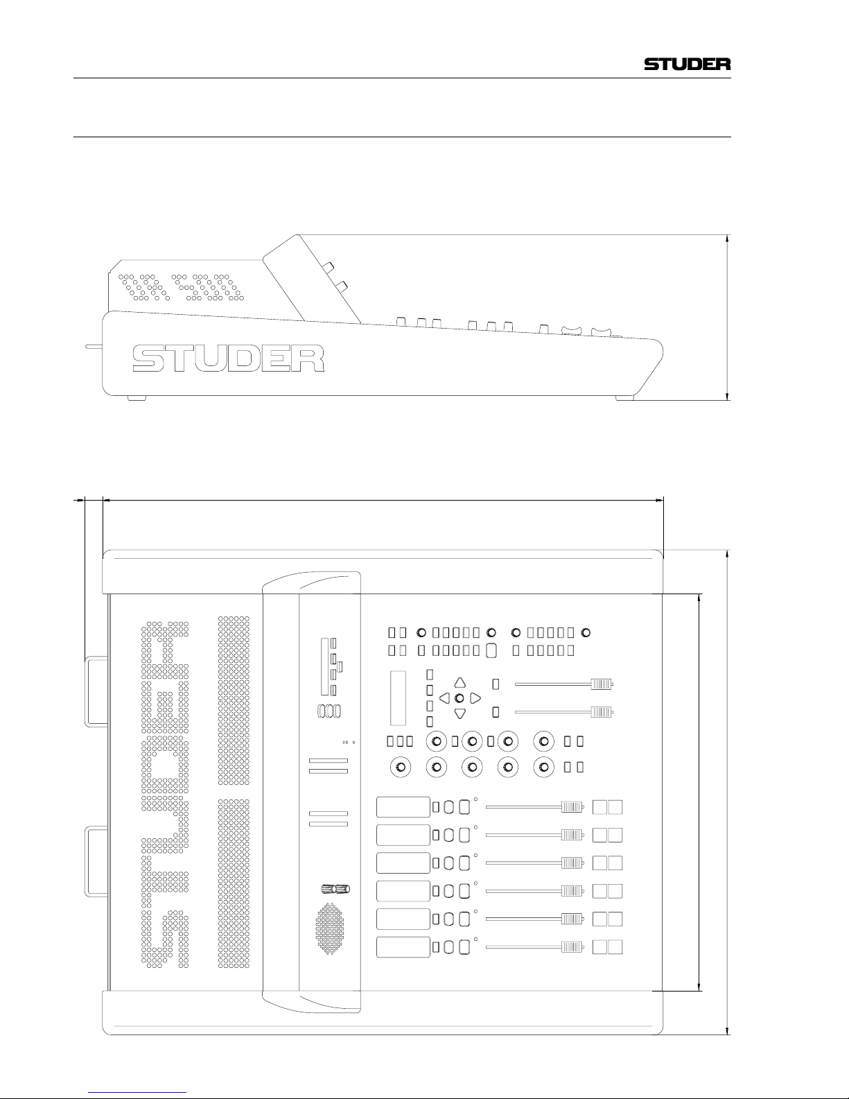
550 mm
636 mm
450 mm
20 mm
188 mm
2.3.2 Mechanical Dimensions
Page 28
OnAir 500 Digital Mixing Console
Operating Elements 3-1
Date printed:
30.07.04
3 OPERATING ELEMENTS
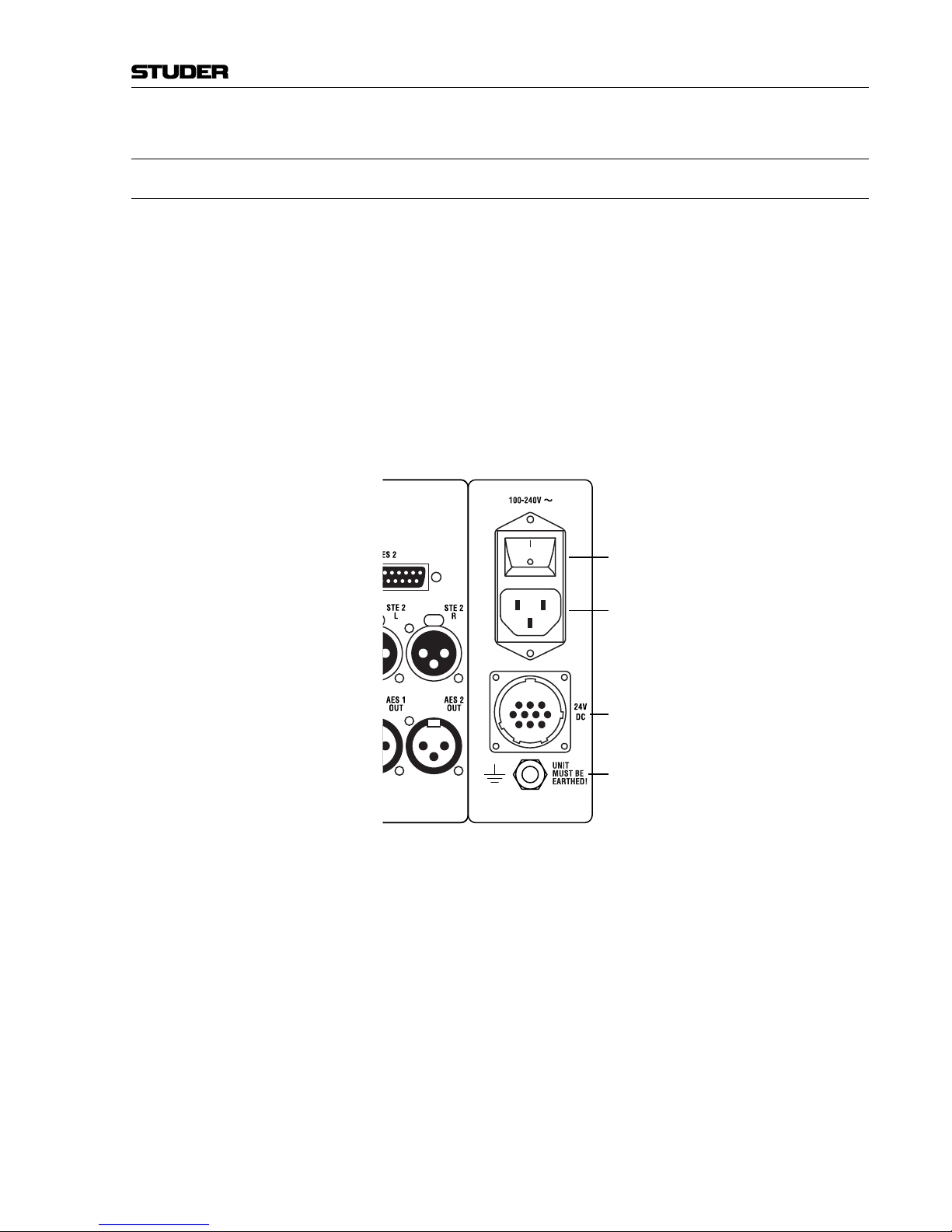
3.1 Power Switch
The mains power switch is located on the rear side of the console, next to the
power inlet.
In case of DC operation of the console using an external power supply, a
battery or an UPS, the power switch is without function. In such a case, an
external power switch has to be foreseen by the installer.
The mains inlet and the DC supply inlet can be used at the same time for
quasi-redundant operation.
In case of quasi-redundant operation, the POWER ALARM LED on the meter
bridge illuminates and warns the operator as soon as either one, the AC or
the DC supply fails while the other one keeps up running the console. In
addition, a power alarm signal is active on one of the pins of the 24V DC
connector.
For pin assignment of the 24V DC connector refer to chapter 12.2.5.
213
9810
47
132
2
132
1
Power Switch (active for Mains Supply only)
IEC Mains Inlet
DC Supply Inlet
Earthing Lug
Page 29
OnAir 500 Digital Mixing Console
3-2 Operating Elements Date printed:
30.07.04
[1]
[3]
[4]
[5]
[6]
[7]
[2]
[8]
Page 30

OnAir 500 Digital Mixing Console
Operating Elements 3-3
Date printed:
30.07.04
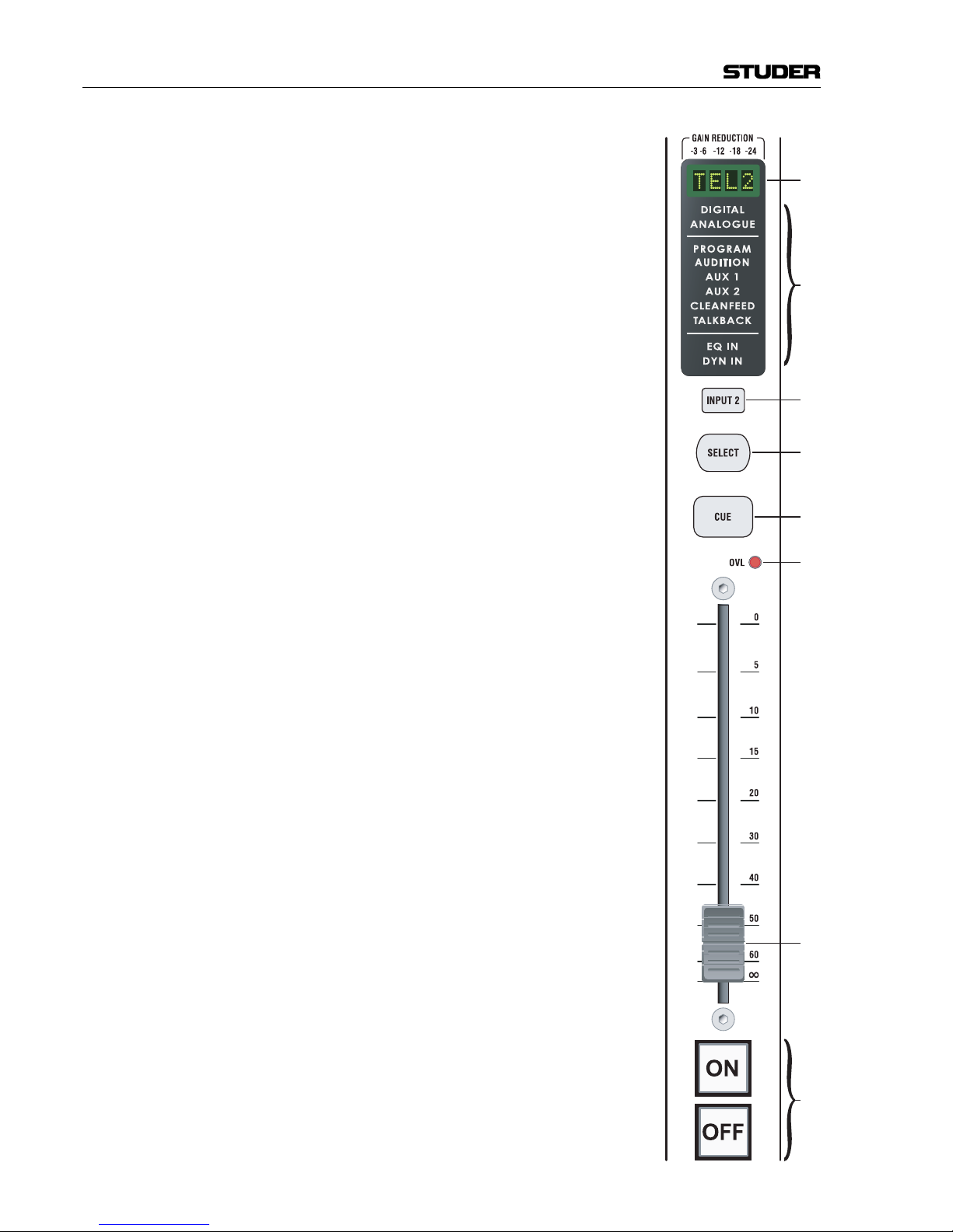
3.2 Channel Strip
Input Display [1] This four-character display normally indicates the currently active channel
input (the name of which can be edited, refer to chapter 4.12). If the channel’s
dynamics processor is active, it indicates compressor/limiter gain reduction
and gate activity instead (see chapter 6).
Status Window [2] The status window contains individual displays that give constant visual in-
formation on:
• Whether the input source is ANALOGUE or DIGITAL.
• Whether the channel is assigned to the PROGRAM or AUDITION out-
puts.
• Whether the AUX 1 or AUX 2 sends are active on the selected channel
(the legend will illuminate as soon as either of the AUX 1 or AUX 2 sends
are opened).
• Whether the channel has been configured as a CLEANFEED source.
• Whether the channel has been configured as the TALKBACK channel
• Whether the EQ IN button is active on the channel
• Whether the channel’s dynamics processor is active or not (DYN IN).
INPUT 2 [3] The INPUT 2 button indicates whether input 1 or input 2 is the current input
source for the channel. If the INPUT 2 button is dark, then input 1 is active. If
the INPUT 2 button is illuminated then input 2 is active.
Note: The REV TB1 (reverse talkback input) and the four external monitoring in-
puts (on the ANALOGUE I/O 37-pin D-type connector) cannot be used as
channel inputs.
SELECT [4] When the SELECT button is pressed, the edit strip will be assigned to the
selected channel. The SELECT button is also used in conjunction with some
of the setup menus, for fast configuration of console functions.
CUE [5] The CUE button routes the channel source to the CUE/PFL bus. This allows
the presenter to listen to any channel source before the fader is opened. The
CUE button can also be used together with the TALK button [34] to send
talkback, usually the presenter’s microphone, to a designated cleanfeed output. The CUE button can be latched by giving it a short press; alternatively it
can have a momentary action by holding it down.
OVL LED [6] The OVL LED indicates clips occurring in the digital domain.
Channel Fader [7] The channel fader is a high-quality, 100 mm fader with a logarithmic scale.
Any channel fader can be configured in the Assign Channels menu to start
external equipment and to trigger the timers (refer to chapters 4.17 and 9.2).
ON / OFF [8] The large ON and OFF buttons are used to switch the channel on and off.
They may also be configured for triggering external devices using the remote relay port (refer to chapter 4.17).
Page 31

OnAir 500 Digital Mixing Console
3-4 Operating Elements Date printed:
30.07.04
[9]
[10]
[13]
[12]
[11]
[14]
[15]
[17]
[18]
[16]
[19]
Page 32

OnAir 500 Digital Mixing Console
Operating Elements 3-5
Date printed:
30.07.04
3.3 Edit Strip
The edit strip is a central panel offering all of the usual facilities you would
expect to find on a standard channel strip. The edit strip can be applied to any
channel by pressing the channel’s SELECT button [4]. It will remain active
on the selected channel until the SELECT button of another channel is
pressed.
AUX MASTER [9] Used in conjunction with the AUX 1 and AUX 2 buttons, this control adjusts
the overall send level for either the AUX 1 or AUX 2 bus. When the associated STE button is pressed, both AUX 1 and AUX 2 buttons illuminate, indicating that they are now linked as a stereo pair (AUX 1 = L, AUX 2 = R). In
this case, the AUX MASTER control will adjust the send level as a stereo pair.
The red STE LED found next to the AUX 1 send control will illuminate, showing that stereo link mode is active.
Note: The AUX MASTER control and its associated buttons are always active, re-
gardless of which channel is currently selected to the edit strip.
HF [10] The HF control has a shelving characteristic and offers 10 dB of cut/boost at
a frequency of 10 kHz.
LF [11] The LF control has a shelving characteristic and offers 10 dB of cut/boost at
a frequency of 100 Hz.
MF [12] The MF control has a semi-parametric characteristic and offers 10 dB of cut/
boost. The center frequency is adjusted with the FREQ control [13].
FREQ [13] The FREQ control selects the frequency of the MF EQ band in a range of
500 Hz to 8 kHz.
HPF [14] The HPF button inserts the variable high-pass filter into the channel. This is
useful for reducing unwanted low frequency interference. The choice of cutoff frequencies for the high-pass filter is 80, 100, 150, 200, 250 Hz.
EQ IN [15] The EQ IN button switches the EQ section on and off, excluding the high-
pass filter (HPF) which is not affected by this control.
AUX 1, AUX 2 [16] Each channel can be routed to the AUX 1 and AUX 2 buses. Turning either
control clockwise will activate the AUX send, and the corresponding AUX
legend in the status window of the selected channel will illuminate.
Turning either control fully anti-clockwise (–∞) will mute the AUX send,
and the corresponding AUX legend in the status window will extinguish.
The AUX MASTER control determines the overall level of the AUX 1 or
AUX 2 bus output.
The PRE button next to each AUX control switches the AUX send between
pre- and post-fader modes (when selected, the PRE button will turn amber).
PRE-fader mode will enable an AUX signal to be sent even if the fader is
down. If AUX 1 and AUX 2 are stereo-linked, the PRE button and AUX send
level control for AUX 2 will be disabled.
Page 33

OnAir 500 Digital Mixing Console
3-6 Operating Elements Date printed:
30.07.04
[9]
[10]
[13]
[12]
[11]
[14]
[15]
[17]
[18]
[16]
[19]
Page 34

OnAir 500 Digital Mixing Console
Operating Elements 3-7
Date printed:
30.07.04
GAIN [17] When using EQ, the total amount of signal present on a channel can be radi-
cally changed. This can result in clipping, even if the original signal level
was ideal before EQ was applied. Clipping is indicated by the OVL LED on
the corresponding channel strip. The GAIN control can modify the digital
signal level by ±12 dB to compensate for signals that are either too soft or
too loud.
PAN / BAL [18] When a stereo source is routed to the stereo outputs using one or both of the
PROG/AUD buttons [19], the PAN/BAL control will act as a balance control
adjusting the amount of signal sent to the left and right outputs of the selected stereo bus.
If the selected channel is using a mono source, then the PAN/BAL control will
pan the signal between the left and right outputs of the selected stereo bus.
PROG / AUD [19] Each button routes the selected channel to either the PROG or AUD output
bus. When routed, the corresponding legend will illuminate in the status window. The channel fader adjusts the level of the signal in that channel being
sent to the PROG and AUD output buses.
Page 35

OnAir 500 Digital Mixing Console
3-8 Operating Elements Date printed:
30.07.04
[21][22]
[20]
[21][22]
[20]
Page 36

OnAir 500 Digital Mixing Console
Operating Elements 3-9
Date printed:
30.07.04
3.4 Monitoring Section
Both STUDIO MONITOR and CONTROL ROOM MONITOR sections operate in
an identical manner and can be thought of as “zones”.
In the CONTROL ROOM zone, the presenter and usually the console are located. Any monitor source selected using the monitor source selector buttons (EXT 1, EXT 2, EXT 3, EXT 4, AUX 1, AUX 2, PROG, and AUD) will appear
on the control room monitor speakers. The METER 1 meters will display the
level of the currently selected monitor source if the MONITOR button [39] on
the meter bridge is selected.
The STUDIO zone would normally be a recording area acoustically isolated
from the control room. It has the same monitor source select options as those
for the CONTROL ROOM.
The MONITOR control next to the MUTE buttons in each section adjusts the
output level sent to the MONITOR CTRL RM and MONITOR STUDIO outputs.
The MUTE buttons will silence the speakers in either zone when selected.
The output to the headphones remains active when a MUTE button is selected.
The built-in CUE loudspeaker [40] will also mute together with the control
room monitor speakers.
Both MUTE buttons can be configured to be automatically triggered by any
or by all of the channel faders (refer to chapter 4.3).
PHONES [20] The controls labeled STUDIO PHONES and CR PHONES each adjust their as-
sociated headphone volumes (STUDIO PHONES and C/ROOM PHONES outputs at the rear of the console; for the control room phones, there is an additional socket at the console’s front).
Note: The volume of the guest headphone output (GUEST PHONES, at the rear of
the console) is set using the Guest Headphones Level menu page,
refer to chapter 4.10).
What each zone hears, whether over the monitors or the headphones is selected by using one of the monitor source buttons (EXT 1, EXT 2, EXT 3,
EXT 4, AUX 1, AUX 2, PROG, and AUD).
The available options are:
• EXT 1, 2, 3, 4 – External stereo inputs which cannot be routed to any channel (e.g. an off-air receiver for program monitoring).
• AUX 1, 2 – AUX sends. Both the AUX 1 and AUX 2 buttons will illuminate
if the AUX MASTER control [9] is in stereo mode.
• PROG, AUD – The main stereo master outputs from the console.
Note: The PFL/CUE bus is automatically routed to the control room headphones,
but not the to the studio headphones. Pressing the AUTO button in the studio
headphones section will allow the PFL/CUE bus to be routed automatically
to the studio headphones as well.
AUTO CUE [21] When selected, the associated monitor loudspeakers will automatically
switch from the previously selected source to the PFL/CUE bus when any
CUE button is pressed. Pressing the AUTO button in the STUDIO MONITOR
section will also route the PFL/CUE bus to the studio headphones.
SPLIT CUE [22] If the SPLIT button is pressed, then the left earpiece of the studio or the con-
trol room headphones will provide PFL/CUE, and the right earpiece will
carry a mono sum of whatever stereo source is selected above.
Note: The guest headphones cannot be split in this manner.
Page 37

OnAir 500 Digital Mixing Console
3-10 Operating Elements Date printed:
30.07.04
[31]
[32]
[34]
[23]
[29]
[24] [25] [26]
[35] [36]
[27]
[28]
[33]
[30]
OnAir 500
STUDER
Page 38

OnAir 500 Digital Mixing Console
Operating Elements 3-11
Date printed:
30.07.04
3.5 Master Section
LC Display [23] Global console parameters and channel settings can be viewed and edited
from this screen. The LC display can operate in one of six modes which are
selected either by pressing one of the four buttons directly underneath the
LC display window, by pressing the FX EDIT button [32] in the Lexicon
TM
effects section, or by pressing the timer SETUP button [44] found below the
left-hand timer (TIMER 1).
The available modes are:
SETUP [24] Enters the setup menu pages
DYN [25] Enters the dynamics menu pages
EDIT [26] LCD screen display of edit strip parameter adjustments.
PRESETS [27] Enters the presets menu pages
FX EDIT [32] Enters the LexiconTM FX edit menu pages
SETUP [44] (timer section) Enters the timer setup menu pages
Note: If none of the above modes is active, the display will show the currently last
recalled preset name in the bottom line.
t u z i Arrow Buttons [28] Used in conjunction with the LC display above, the t u z i arrow buttons
allow the user to navigate the various menus in order to select parameter
data.
PARAMETER [29] This rotary encoder is used to scroll through lists of available parameter data.
When making alphanumeric entries, you can scroll from A...Z (upper case),
a...z (lower case), and 0...9.
The z (up) arrow button will step through the numeric values 0...9 only, and
the i (down) arrow button will insert a space or certain punctuation characters.
Most changes happen in real time, i.e., as the encoder is turned, new data is
applied immediately. The only time you need to confirm an entry is if the
SETUP button [24] flashes. The navigation buttons will illuminate to guide
you to the next line of the LC display, or to the next branch of the menu tree.
LexiconTM Effects Processor The in-built LexiconTM effects processor offers an array of different digital
effects including reverb, delay, chorus, flange, and others.
AUX 1 / AUX 2 SOURCE [30] The two AUX 1 and AUX 2 SOURCE buttons select the input signal to the ef-
fects processor from either the AUX 1 or AUX 2 bus. When the AUX MAS-
TER control [9] is in stereo mode (STE button illuminated), then both AUX 1
and AUX 2 buttons in the effects control section will illuminate, indicating
that the processor is receiving a stereo input. It is not possible to deselect the
input to the effects processor, i.e., the processor is always assigned to one or
the other AUX source. The amount of effect which is heard (i.e. the effects
mix) is adjusted by controlling the input to the processor by using the AUX
MASTER control; alternatively, the FX LevelOut parameter in the Cur-
rent FX Setup menu can be used.
FX IN [31] The FX IN button switches the effects on or off. When the FX IN button is
illuminated, the effects are switched on.
FX EDIT [32] Pressing the FX EDIT button puts the LC display into the effects editing mode
where different effects parameters can be edited (refer to chapter 7).
Page 39

OnAir 500 Digital Mixing Console
3-12 Operating Elements Date printed:
30.07.04
[31]
[32]
[34]
[23]
[29]
[24] [25] [26]
[35] [36]
[27]
[28]
[33]
[30]
OnAir 500
STUDER
Page 40

OnAir 500 Digital Mixing Console
Operating Elements 3-13
Date printed:
30.07.04
PROG / AUD Master Faders [33] The master faders are identical in specification to the channel faders, they
adjust the amount of signal sent to the PROG and AUD main stereo output
buses. These two faders can be completely bypassed (i.e., set to full output at
0 dB) via the setup menu if required.
TALKBACK DESTINATION Selection
TALK [34] The main TALK button activates the internal talkback function which routes
the assigned talkback channel to any one of three possible destinations:
STUDIO [35] Studio phones output,
GUEST [36] Guest phones output, or
Talkback to a selected line/cleanfeed output.
There can be only one talkback channel assigned using the setup Menu –
usually the presenter’s microphone. The associated STUDIO [35] and GUEST
[36] talkback destination buttons will route talkback to the Studio and/or
Guest headphones.
The main TALK button [34] can be latching (short press) or momentary (by
holding it for as long as required), and either of the STUDIO and GUEST
talkback destination buttons can then send talkback to the intended destination when pressed.
In conjunction with the main TALK button, any channel that has been assigned to a mix-minus (cleanfeed) output using the setup menu (see chapter
4.13) will be able to send talkback through that same cleanfeed output when
its corresponding PFL button is active. To enable this mode of operation,
both the TALK and CUE buttons must be illuminated, either latched or momentarily.
Page 41

OnAir 500 Digital Mixing Console
3-14 Operating Elements Date printed:
30.07.04
3.6 Meter Bridge
[39]
[37]
[38]
[41] [43]
[42] [45] [44][40]
For the metering, two 2-channel 30-LED bargraph meters (METER 1 and
METER 2) are provided. Both have either PPM or VU characteristics (indi-
cated by the yellow PPM or VU LEDs). The characteristics selection is factory-set and has been specified at the time of ordering your console. Above
both meters, there are two LED bargraph correlation indicators allowing to
judge the mono compatibility of your mix (“+1” indication: L/R signals in
phase, best mono compatibility; “–1” indication: L/R signals out-of-phase,
no mono compatibility).
METER 1 Source Selector The audio source displayed by METER 1 can be selected by one of three
source selector buttons:
PROGRAM [37] Used to monitor the output of the main PROG bus (post fader).
AUDITION [38] Used to monitor the output of the main AUD bus (post fader).
MONITOR [39] When active, the METER 1 will display the signal currently selected in the
CONTROL ROOM MONITOR section.
Alternately, the signal from any channel with a CUE button active will be
displayed. If SPLIT CUE [22] mode is selected, the left-channel meter will
display the CUE signal, and the right-channel meter the main program output
signal during a CUE condition.
Note: For the METER 2, the selection of the same sources (PROG bus, AUD bus,
CR monitor selection) is done in the Second Metering Source menu
(refer to chapter 4.30).
Page 42

OnAir 500 Digital Mixing Console
Operating Elements 3-15
Date printed:
30.07.04
CUE / TALKBACK Speaker [40] The built-in speaker can relay signals from the CUE bus and talkback signals
(i.e., talkback from an external location, fed via the REV TB1 IN connector on
the rear panel).
These signals are entirely independent of any monitor settings; they can each
be adjusted in volume by using the associated controls marked TALKBACK
[41] and CUE [42]. The CUE control adjusts the overall loudspeaker volume,
whereas the TALKBACK control only adjusts the talkback signal level.
Notes: The TALKBACK volume control cannot be turned all the way down. This is
intended and normal to protect essential communications.
The built-in speaker will automatically mute along with the CONTROL ROOM
MONITOR MUTE button.
TIMER 1, TIMER 2 [43] Both timers can be triggered either manually (using the associated START,
STOP and RESET buttons), or automatically, from any of the channel faders
if programmed to do so (see chapter 9.2).
Note: The TIMER 2 button directly below the timer buttons allow you to switch the
manual controls between TIMER 1 and TIMER 2.
SETUP [44] The SETUP button in the timer section enters the timer setup menu pages
(refer to chapter 9).
POWER ALARM LED [45] In case of redundant supply operation (i.e., AC and DC supply used simulta-
neously), this indicator illuminates and warns the operator as soon as either
one, the AC or the DC supply fails while the other one keeps up running the
console. In addition, a power alarm signal is active on one of the pins of the
24V DC connector.
Page 43

OnAir 500 Digital Mixing Console
3-16 Operating Elements Date printed:
30.07.04
Page 44

OnAir 500 Digital Mixing Console
Date printed: 10.08.05
4 THE MENU PAGES
Pressing the SETUP button accesses the setup menu pages where specifi c con-
sole confi gurations can be programmed.
You will use the SETUP button, the PARAMETER encoder and the t u z i
arrow buttons to navigate around the menu pages.
OnAir 500
STUDER
On pressing the SETUP button, the LC display will read:
[Select Page]
..............
You may now use the PARAMETER encoder to select one of the menu pages
that you would like to enter. Press the SETUP button to enter the selected menu
page.
The menu list as found on the Studer OnAir 500:
A menu tree diagram is printed on the next page.
.oNuneM.oNuneM.oNuneM
1stupnIgolanA11ycneuqerFFPH12lecnacotuAEUC
2lennahCngissA21gnimaNtupnI22leSlennahCSCR
3gnituMotuA31stuptuOFC/eniL32puteSSCR
4sesahPlennahC41niPtuokcoL42stupnIetomeR
5ecruoSkcolC51puteStuokcoL52noisreVerawtfoS
6stuptuOlatigiD61sutatStuokcoL62metsyS
7.vdAtuOlatigiD71tratSenihcaM72ngissAkcabklaT
8sgnitteSyalpsiD81sredaFretsaM82stuptuOFIDT
9niaG)tupnI(PIlanretxE91pukcaBIDIM92.vdAtuOFIDT
01leveLsenohpdaeHtseuG02tuptuOonoM03ecruoSreteMdn2
Menu Pages 4-1
Page 45

OnAir 500 Digital Mixing Console
Date printed: 10.08.05
4-2 Menu Pages
Menu Tree Diagram:
4.1 Analog Inputs
The analog inputs page allows fast access to all of the analog inputs available
on the OnAir 500.
The gain settings for each input can be adjusted here; where applicable, 48 V
phantom power can be switched on or off.
Options are as follows:
epyTtupnIegnaRniaGrewoPmotnahPV84
4,3,2,1eniL/ciMBd06+...0seY
1kcabklaTesreveRBd06+...0seY
2,1stupnIoeretSBd81+...0oN
Selected analog stereo inputs also have a choice of the following prefer-
ences:
edoMnoitcA
RL
edomtluafeD thgirdnatfelehtotdeilppuseraslangistupnithgirdnatfel
ylevitcepser,slennahc
LL tfeL otdeilppussiylnolangistupni htob slennahcthgirdnatfeleht
RR thgiR otdeilppussiylnolangistupni htob slennahcthgirdnatfeleht
LReraslangistupnithgirdnatfeL )deppaws(desrever
All settings made here can be stored as part of a snapshot preset for instant
recall.
Selecting and Adjusting an Analog Input:
1 Press the SETUP button found below the LC display . This will enter the setup
mode.
2 Use the PARAMETER encoder to scroll through the menu pages to locate the
Analogue Inputs menu. The LC display will show:
[Select Page]
Analogue Inputs
3 Press the fl ashing SETUP button again. The LC display will read:
Mic/Lin 1 M/L1->
Gain: + 4dB
4 Use the z (up) arrow button to select the upper line of the LC display. Then
select the input to be adjusted, either by using the PARAMETER encoder, or by
pressing the SELECT button (and possibly the INPUT 2 button) of the desired
input channel. This is very handy for quickly accessing different microphone
gain levels in a multi-microphone application.
Please note that the reverse talkback channel can be selected only by using
the PARAMETER encoder.
If you press the SELECT button of a digital input channel, this page is not used,
and a corresponding message is displayed.
(Values indicated in italics and brackets are valid for OnAir 500 Modulo 12-fader versions only)
Mic/Lin 1…4
(8)
Gain: 0…60dB Phantom Pwr ON/OFF
RTB1/FTB2
(…RTB2/FTB3)
Gain: 0…60dB Phantom Pwr ON/OFF
1 Analogue Inputs
STE1…2
(4)
Gain: 0…18dB
2 Assign Channel
Source Selection
Ch01.1…Ch01.2
…
Ch06.1…Ch06.2
(…Ch12.1…12.2)
1kHz
none
M/L1…4
(8)
STE1…2
(4)
AES1…4
(8)
*
SPD1
(…2)
TDF1…8
TD12…78
3 Auto Muting
Channel 1…6
(12)
Mutes: Nothing
Mutes: Studio
Mutes: ControlRm
Mutes: Stu&CtlRm
4 Channel Phases
Mono/Ste Ch 1…6
(12)
Phase Normal / Inverted
5 Clock Source
Wordclock Source Internal 48.0kHz
Internal 44.1kHz
External BNC
External AES11
6 Digital Outputs
Output:
SPDIF1
(…2)
…AES1…AES2
(4)
Src: Unsourced
Src: Program
Src: Audition
Src: Auxiliaries
Src: LIN/CLNFD12
Src: LIN/CLNFD34
(Src: LIN/CLNFD56)
FS: Undefined
FS: 32kHz
FS: 44.1kHz
FS: 48kHz
Config: Manual
WL:16Bit
WL:20Bit
WL:24Bit
Pro:PRO
Pro:CON
7 Digital Out Adv.
Output:
SPDIF1
(…2)
…AES1…AES2
(4)
Config: Auto
8 Display Settings
LCD Contrast: 00…63
9 External IP Gain
EXT1…4 Gain: –
dB…+18dB
10 Guest Headphones
Level: –
dB…0dB
11 HPF Frequency
Channel 1…6
(12)
HPF Freq:80…250Hz
12 Input Naming
MIC/LINE1…4
(8)
:
STEREO 1…2
(4)
:
AES/EBU1…4
(8)
:
SPDIF1
(…2)
:
TDIF1…8:
STE TDIF1…4:
<xxxx>
Mode:Direct OP Channel 1
…
Channel 6
(12)
Mode:Prog Mix- Channel x
Mode:Ste1 Mix- Channel 1
…
Channel 6
(12)
Mode:Aud Mix- Channel x
Mode:Ste2 Mix- Channel 1
…
Channel 6
(12)
Mode:Cont Talk
13 Line/CF Outputs
Line Output: 1…4
(6)
Outs 1+2 Mono
Outs 1+2 Stereo
Mode:Unsourced
Please Enter New PIN: xxxx
14 Lockout PIN
Confirm New PIN: xxxx
15 Lockout Setup
All Functions
AUX Sends
Control Room Src
Channel On
Dynamics
EQ/HPF
FX All-(In/Out)
FX In/Out
Input 2 select
Meter Source
Pan/Balance
Preset Rcl/St/Dl
Preset St/Dl
Prog/Aud Routing
Setup Menus
Split/Auto
Studio Src
Talk to C/F
Timer
Trim
unlocked / locked
16 Lockout Status
Disabled / Enabled
Not Assigned
Remotes02 Rly01…12
(Remotes03
Rly01…12)
17 Machine Starts
Input: MIC/LINE1…4
Input: STEREO 1…2
Input: AES/EBU1…4
Input: SPDIF1
Input: TDIF1…8
Input: STE TDIF1…4
(Input: MIC/LINE5…8)
(Input: STEREO 3…4)
(Input: AES/EBU5…8)
(Input: SPDIF2)
Rem. Mode: Off
Latch
Moment
18 Master Faders
Enabled / Disabled
19 MIDI Backup
Receive Data
Send Desk Presets
Send All Presets
Send 1 DYN Prset
Send DYN Presets
Send 1 FX Preset
Send FX Presets
Send All Data
Execute
20 Mono Output
Source: Program
Source: Audition
Source: Aux 1+2
Source: Aux 1
Source: Aux 2
21 CUE Autocancel
Disabled / Enabled
22 RCS Channel Sel
RCS: A…B…C…D
Sel 01…06
(12)
23 RCS Setup
Disabled
Channels AB
Channels ABC
Channels ABD
Channels ABCD
24 Remote Inputs
Remote I/P: 1…4 No Action
Enable RevTB
Mute Channel 1…6
(12)
25 Software Version
Version: Vx.xx
Build: xxxx
FPGA file date xx-xx-xx xx:xx
Temp Sensor xxxxxxxxxxxx
MASPIC: on prt 4; SW Version: x.xx
INPIC1: on prt 3
(2)
; SW Version: x.xx
(INPIC2: on prt 3; SW Version: x.xx)
Flash Bootrom Version: x.x
Auto Edit: Off / On
TalkBack Swap: Off / On
26 System
FX Send: Post Master / Pre
Master
27 Talkback Assign
Fwd/RevTB Source None
Channel 1…6
(12)
28 TDIF Outputs
Output: TDIF1&2…7&8 Src: Unsourced
Src: Program
Src: Audition
Src: Auxiliaries
Src: LIN/CLNFD12
Src: LIN/CLNFD34
(Src: LIN/CLNFD56)
Sample Rate: Auto
48kHz
44.1kHz
32kHz
Other
29 TDIF Out Adv.
O/P Buffer: Other / Soundcraft
30 2nd Meter Source
Program / Audition / Monitor
* For 12-fader OnAir 500 Modulo versions only: Please note that the SPD1
input can be routed to faders 1…6 only, while the SPD2 input can be rout ed to faders 7…12 only.
Page 46

OnAir 500 Digital Mixing Console
Menu Pages 4-3
Date printed: 10.08.05
5 Once you have selected the desired input you may then use the i (down)
arrow button to select the gain adjustment field, then adjust the gain by using
the PARAMETER encoder.
Note: It is recommended that input gain adjustments are performed in conjunction
with selecting the CUE button on the corresponding channel, and by switching the main meter (METER 1) to MONITOR mode, so that adjustments to the
input gain level can be accurately displayed.
6 For mic/line inputs, the u (right) arrow button can then be used to select the
Phantom Pwr ON/OFF field of the display, and the PARAMETER encoder
to select either on or off.
Note: When switching 48 V phantom power on or off it is strongly recommended that
the relevant channel’s ON and CUE buttons be switched off to avoid possible
damage to monitor speakers.
For stereo inputs, the u (right) arrow button can be used to enter the L R, L L,
R R, R L select field of the display, and the PARAMETER encoder can the be
used to select the desired mode.
Note: For information on phase inversion, refer to chapter 4.4.
7 Pressing the SETUP button will exit this menu. However, the SETUP button will
still flash, the next menu can be selected for adjustment. To exit completely,
press one of the DYN, EDIT, or PRESETS buttons twice.
Page 47

OnAir 500 Digital Mixing Console
4-4 Menu Pages
Date printed: 10.08.05
4.2 Assign Channel
The Studer OnAir 500 is designed to offer maximum flexibility concerning
input routing. Every channel has two inputs that can handle mono or stereo,
analog or digital input sources. These input signals can be sourced from a
pool of digital or analogue inputs (see table below).
A complete input set-up configuration can then be saved as part of a snapshot
preset for instant recall. This allows the operator to quickly reconfigure the
console for different applications.
epyTtupnIoeretSroonoMlatigiDrogolanA
enoTtseTzHk1onoMlatigiD
enoN--
4...1eniL/ciMonoMgolanA
2ETS,1ETSoeretSgolanA
4...1SEAoeretSlatigiD
1FIDP* SoeretSlatigiD
8...1FIDTonoMlatigiD
8-7...2-1FIDToeretSlatigiD
* For 12-fader OnAir 500 Modulo versions only: Please note that the SPDIF1
input can be routed to the faders 1...6 only, while the SPDIF2 input can be
routed to the faders 7...12 only.
Selecting and Assigning the Input Source:
1 Press the SETUP button found below the LC display. This will enter the setup
mode.
2 Use the PARAMETER encoder to scroll through the menu pages to locate the
Assign Channel menu. The SETUP button will flash upon selection.
3 Press the SETUP button to enter the assign channel mode. The LC display
will read:
Source Selection
Ch01.1: M/L1
You can now choose what type of input source you would like to assign, and
to which of the two inputs of the chosen channel you would like to assign the
input.
4 Press the SELECT button on the desired channel and select either input 1 or
input 2 using the INPUT 2 button (it will be unlit for input 1, or lit for input
2).
The LC display will now show the selected channel, and which input is cur-
rently selected. If for example the SELECT button is pressed on channel 1
while the INPUT 2 button is illuminated, input 2 will become active. The LC
display will read:
Source Selection
Ch01.2: M/L3
Page 48

OnAir 500 Digital Mixing Console
Menu Pages 4-5
Date printed: 10.08.05
Alternatively, if the SELECT button is pressed on channel 1 while the INPUT 2
button is not illuminated (meaning that input 1 is active), the LC display will
read:
Source Selection
Ch01.1: M/L1
5 Now use the PARAMETER encoder to scroll through the selection of different
inputs until you reach the desired input source.
As you scroll through the different input sources you will see the names of
those inputs appearing on the four-character LED display at the top of the
selected channel strip.
You will also notice that the DIGITAL or ANALOGUE legend just below
the four-character LED display on the selected channel will illuminate, to
confirm that the input source is either digital or analog.
6 You may now repeat the procedure above for the alternate input on the selected
channel.
7 If you are happy with your selection press the SELECT button on the next
channel you want to set-up.
8 Pressing the SETUP button will exit this menu. However, the SETUP button will
still flash, the next menu can be selected for adjustment. To exit completely,
press one of the DYN, EDIT, or PRESETS buttons twice.
Note: You can also use the PARAMETER encoder to select the channel and input
number without using the SELECT buttons to select the channels.
Page 49

OnAir 500 Digital Mixing Console
4-6 Menu Pages
Date printed: 10.08.05
4.3 Auto Muting
The OnAir 500's channel faders can be configured in such a way that when
a designated fader is opened, a number of different mute activations can be
performed.
The available options are as follows:
dnammoCetuMnoitcA
gnihtoNdetavitcaerasetumoN
oidutSylnosrekaepsrotinomoidutsetuM
mRlortnoCylnosrekaepsmoorlortnocetuM
mRltC&utSsrekaepsmoorlortnocdnaoidutsetuM
Configuring a Channel for Mute Activation:
1 Press the SETUP button found below the LC display. This will enter the setup
mode.
2 Use the PARAMETER encoder to scroll through the menu pages to locate the
Auto Muting menu page. The SETUP button will flash upon selection.
3 Press the SETUP button to enter the Auto Muting set-up mode. The LC display
shows the selected channel and will read:
Channel 1
Mutes: Nothing
4 Press the SELECT button on the channel you want to configure.
5 Now use the PARAMETER encoder to select the type of mute activation you
require (refer to the table above).
6 Pressing the SETUP button will exit this menu. However, the SETUP button will
still flash, the next menu can be selected for adjustment. To exit completely,
press one of the DYN, EDIT, or PRESETS buttons twice.
Page 50

OnAir 500 Digital Mixing Console
Menu Pages 4-7
Date printed: 10.08.05
4.4 Channel Phases
In certain applications it may be necessary to reverse the phase of one side of
an incoming stereo source to correct for phase problems. There may also be
times when inverting the phase of a (mono) microphone may be necessary
to prevent phase problems with other microphones set up nearby.
For stereo inputs, the left output channel is inverted, if L R or R L has been
selected in the “Analog Inputs” menu (see chapter 4.1); in the remaining (R R,
L L) cases, however, always both output channels are inverted.
Reversing the Phase of a Stereo or Mono Input Source:
1 Press the SETUP button found below the LC display. This will enter setup
mode.
2 Use the PARAMETER encoder to scroll through the menu pages to locate the
Channel Phases menu page. The SETUP button will flash upon selec-
tion.
3 Press the SETUP button to enter the channel phases set-up mode. The LC
display will show the current selection:
Mono Ch 1 Phase
Normal
4 Press the SELECT button on the channel you want to edit. The selected channel's
number should appear in the LC display. The display will also show whether
the selected channel is mono or stereo.
5 Use the i (down) arrow button to select the Normal/Inverted field of
the display.
6 You may now use the PARAMETER encoder to select between “Normal” or
“Inverted”.
7 Pressing the SETUP button will exit this menu. However, the SETUP button will
still flash, the next menu can be selected for adjustment. To exit completely,
press one of the DYN, EDIT, or PRESETS buttons twice.
Page 51

OnAir 500 Digital Mixing Console
4-8 Menu Pages
Date printed: 10.08.05
4.5 Clock Source
The OnAir 500 can operate at either 44.1 or 48 kHz when set to it s own
internal wordclock, but can also be configured to lock to incoming wordclock
appearing at either the AES/EBU or S/PDIF digital inputs.
Note: The four AES/EBU digital inputs and the S/PDIF digital input incorporate
sample rate converters (SRC) which allows external digital signals to be connected without the need for the console to be synchronized to the incoming
wordclock contained in the digital source signal.
Configuring the Clock Source: 1 Press the SETUP button found below the LC display. This will enter the setup
mode.
2 Use the PARAMETER encoder to scroll through the menu pages to locate the
Clock Source menu page. The SETUP button will flash upon selection.
3 Press the SETUP button to enter the clock source setup mode.
snoitpOelbaliavA
zHk0.84lanretnI
zHk1.44lanretnI
CNBlanretxE
11SEAlanretxE
The LC display will show the current selection:
Wordclock Source
Internal 48.0kHz
4 Use the PARAMETER encoder to select which wordclock source you want to
use. The SETUP button will flash.
5 Press the SETUP button to store the new clock settings.
6 Pressing the SETUP button will exit this menu. However, the SETUP button will
still flash, the next menu can be selected for adjustment. To exit completely,
press one of the DYN, EDIT, or PRESETS buttons twice.
Note: If wordclock is lost whilst connected to an external wordclock source, the
following display appears:
WORDCLOCK LOST!
SET TO INT 48K
Page 52

OnAir 500 Digital Mixing Console
Menu Pages 4-9
Date printed: 10.08.05
4.6 Digital Outputs
The OnAir 500 has two AES/EBU digital outputs and one S/PDIF digital
output. These outputs can be configured to output a number of different source
signals.
Configuring the Digital Outputs:
1 Press the SETUP button found below the LC display. This will enter the setup
mode.
2 Use the PARAMETER encoder to scroll through the menu pages to locate the
Digital Outputs menu page. The SETUP button will flash upon selec-
tion.
3 Press the SETUP button to enter the digital outputs set-up mode. The LC
display will show the current selection:
Output: SPDIF1
Src: Audition
4 Use the PARAMETER encoder to select which digital output you want to
use.
snoitceleSelbaliavA
1FIDPS
1SEA
2SEA
5 Press the i (down) arrow button to select the “Src” field, and use the
PARAMETER encoder to choose the source for the selected digital output.
snoitpOelbaliavA
decruosnU
margorP
noitiduA
seirailixuA
)2&1deefnaelC/eniL(21DFNLC/NIL
)4&3deefnaelC/eniL(43DFNLC/NIL
6 Pressing the SETUP button will exit this menu. However, the SETUP button will
still flash, the next menu can be selected for adjustment. To exit completely,
press one of the DYN, EDIT, or PRESETS buttons twice.
Page 53

OnAir 500 Digital Mixing Console
4-10 Menu Pages
Date printed: 10.08.05
4.7 Digital Out Adv. (Advanced)
The settings found in this menu are for configuring the status bits of the
S/PDIF and AES/EBU outputs. In most applications, the “Auto” default
settings for these outputs are used, but in certain circumstances it may be
necessary to make manual adjustments. The table below shows the options
available for each output:
tuptuO.giD
)tuptuO(
edoMgifnoC
)gifnoC(
galFetaRelpmaS
)sF(
droW
)LW(htgneL
galForP
)orP(
1FIDPS
1SEA
2SEA
otuAnoitcelesoN
oN
noitceles
noitcelesoN
launaM
denifednU
zHk23
zHk1.44
zHk84
tiB61
tiB02
tiB42
)lanoisseforP(ORP
)remusnoC(NOC
Working with S/PDIF Devices: When the OnAir 500 is synchronized to an external wordclock source,
most digital devices connected to the console’s S/PDIF digital outputs will
happily synchronize to the wordclock being sent from the console via the
S/PDIF digital output.
In most applications the S/PDIF digital output can be set to “Auto” configure
in the
Digital Out Adv. setup menu.
In the uncommon event that a receiving device connected to the S/PDIF
digital output is not synchronizing correctly, it may be necessary to manually
configure the status bits for the S/PDIF output.
This will normally involve setting the Sample Rate Flag (Fs) to the same
wordclock setting that the OnAir 500 is receiving, and setting the Word
Length (WL) to match that of the device connected to the OnAir 500’s
S/PDIF digital output.
The Pro Flag would normally be set to “Consumer” (
CON), but could be
switched to “Professional” (
PRO) if the CON setting does not work cor-
rectly.
Working with AES/EBU Devices: When the OnAir 500 is synchronized to an external wordclock source, most
digital devices connected to the console’s AES/EBU digital outputs will
happily synchronize to the wordclock being sent from the console via the
AES/EBU digital output.
In most applications the AES/EBU digital output can be set to “Auto” configure
in the
Digital Out Adv. setup menu.
In the uncommon event that a receiving device connected to the AES/EBU
digital output is not synchronizing correctly, it may be necessary to manually
configure the status bits for the AES/EBU digital output.
This will normally involve setting the Sample Rate Flag (Fs) to the same
wordclock setting that the OnAir 500 is receiving, and setting the Word Length
(WL) to match that of the device connected to the OnAir 500’s AES/EBU
digital output.
The Pro Flag would normally be set to “Professional” (
PRO).
Page 54

OnAir 500 Digital Mixing Console
Menu Pages 4-11
Date printed: 10.08.05
Changing Settings: 1 Press the SETUP button found below the LC display. This will enter the setup
mode.
2 Use the PARAMETER encoder to scroll through the menu pages to locate the
Digital Out Adv. menu page. The SETUP button will flash upon selec-
tion.
3 Press the SETUP button to enter the set-up mode. The LC display will show
the current selection:
Output: SPDIF1
Config: Auto
4 You may now use the PARAMETER encoder to select between the S/PDIF 1,
AES/EBU 1, or AES/EBU 2 digital outputs.
5 Once the correct digital output is selected, press the i (down) arrow button
to enter the “
Confi g” field of the LC display.
6 The PARAMETER encoder can now be used to toggle between “
Auto” or
“
Manual” (if “Auto” is selected, there is no further access to the other menu
pages, as these settings are automatically configured).
7 Select “
Manual”. The LC display will now show:
Output: SPDIF1 ->
Config: Manual
8 Press the u (right) arrow button to enter the manual configuration settings
page. The LC display will show:
<- Fs: 44.1kHz
WL:24Bit Pro:PRO
9 You can now use the t u z i arrow buttons to navigate between the Sample
Rate (
Fs), Word Length (WL), and Pro Flag (Pro) parameter settings. The
PARAMETER encoder is used to make the necessary adjustments to the selected
parameters (see the table above for parameter choices).
10 Pressing the SETUP button will exit this menu. However, the SETUP button will
still flash, the next menu can be selected for adjustment. To exit completely,
press one of the DYN, EDIT, or PRESETS buttons twice.
Page 55

OnAir 500 Digital Mixing Console
4-12 Menu Pages
Date printed: 10.08.05
4.8 Display Settings
Setting the Display Contrast: 1 Press the SETUP button found below the LC display. This will enter the setup
mode.
2 Use the PARAMETER encoder to scroll through the menu pages to locate the
Display Settings menu page. The SETUP button will flash upon selec-
tion.
3 Press the SETUP button to enter the display settings set-up mode. The LC
display will show the current selection:
LCD Contrast:
50
4 Use the PARAMETER encoder to adjust the contrast of the LC display.
5 Pressing the SETUP button will exit this menu. However, the SETUP button will
still flash, the next menu can be selected for adjustment. To exit completely,
press one of the DYN, EDIT, or PRESETS buttons twice.
4.9 External IP (Input) Gain
The External IP Gain menu allows the gain of any of the four external
inputs (on the rear of the console) to be adjusted through a range of – ∞ to
+18 dB.
Selecting Input and Gain: 1 Press the SETUP button found below the LC display. This will enter the setup
mode.
2 Use the PARAMETER encoder to scroll to the external input gain menu. The
LC display will read:
External IP Gain
EXT1 Gain: 0dB
3 The EXT1 field will be flashing, and you may now use the PARAMETER
encoder to select
EXT1, EXT2, EXT3 or EXT4.
4 Once you have made your selection, press the u (right) arrow button to select
the Gain field and then use the PARAMETER encoder to adjust the Gain.
5 Pressing the SETUP button will exit this menu. However, the SETUP button will
still flash, the next menu can be selected for adjustment. To exit completely,
press one of the DYN, EDIT, or PRESETS buttons twice.
Page 56

OnAir 500 Digital Mixing Console
Menu Pages 4-13
Date printed: 10.08.05
4.10 Guest Headphones Level
The GUEST headphones output level is adjusted on the Guest Headphones
menu page.
Adjusting the Guest Headphones Level:
1 Press the SETUP button found below the LC display. This will enter the setup
mode.
2 Use the PARAMETER encoder to scroll through the menu pages to locate the
Guest Headphones menu. The SETUP button will flash upon selection.
3 Press the SETUP button to enter the guest headphones level mode. The LC
display will read:
Guest Headphones
Level: -10dB
Adjustment range is – ∞ to 0 dB, the default setting is –10 dB.
4 Pressing the SETUP button will exit this menu. However, the SETUP button will
still flash, the next menu can be selected for adjustment. To exit completely,
press one of the DYN, EDIT, or PRESETS buttons twice.
4.11 HPF Frequency
The HPF Frequency menu allows selecting the cutoff frequency for the
high-pass filter located in the edit strip. Frequencies available are 80, 100,
150, 200 and 250 Hz.
Selecting the HPF Frequency: 1 Press the SETUP button found below the LC display. This will enter the setup
mode.
2 Use the PARAMETER encoder to scroll through the list of menu pages to locate
the HPF Frequency menu. The LC display will read:
Channel 1
HPF Freq: 100Hz
3 The frequency field will be flashing.
4 Press the SELECT button on the channel you want to adjust. The channel
number appears in the upper line of the LC display.
5 Once you have made your selection use the PARAMETER encoder to select
the HPF frequency you wish to use.
7 Pressing the SETUP button will exit this menu. However, the SETUP button will
still flash, the next menu can be selected for adjustment. To exit completely,
press one of the DYN, EDIT, or PRESETS buttons twice.
Page 57

OnAir 500 Digital Mixing Console
4-14 Menu Pages
Date printed: 10.08.05
4.12 Input Naming
Any of the inputs discussed in chapter 4.2 (“Assign Channel”) can be given a
personalized name if required. This is very useful for example in permanent
set-ups where the inputs to the console do not change often.
If a CD player is connected to the AES/EBU 1 input, then the display name
could be changed from AES 1 to read CD_1.
Microphone inputs could also be renamed in this way to show, for example,
the presenter’s name.
Note: The naming of inputs is limited to four characters.
Naming an Input Source: 1 Press the SETUP button found below the LC display. This will enter the setup
mode.
2 Use the PARAMETER encoder to scroll through the menu pages to locate the
Input Naming menu. The SETUP button will flash upon selection.
3 Press the SETUP button to enter the input naming mode. The LC display will
now show the
MIC/LINE1 input, and next to it the current name of that
input. For example:
Select Input
MIC/LINE1:<M/L1>
4 Use the t u (left/right) arrow buttons to select the left-hand field of the LC
display. Then, using the PARAMETER encoder, scroll through the different
input sources until you find the one you want to rename.
5 Now use the t u (left/right) arrow buttons to select one of the four characters
on the right side of the LC display.
6 You may now use the PARAMETER encoder to scroll alphanumerically through
all of the available character choices.
You can also use the z (up) arrow button to increment through numbers, and
the i (down) arrow button to delete the currently selected character or to
create a space.
7 Pressing the SETUP button will exit this menu. However, the SETUP button will
still flash, the next menu can be selected for adjustment. To exit completely,
press one of the DYN, EDIT, or PRESETS buttons twice.
4.13 Line/CF Outputs
The OnAir 500 has four line/cleanfeed outputs that can be used either as direct
outputs (post-fader) for any mixer channel, or for creating a “mix minus”
output from either of the PROG or AUD buses (this is useful for sending a
cleanfeed signal back to an incoming telephone caller).
The talkback bus can also be routed to any of the four line/cleanfeed outputs in
continuous talkback mode. This allows any microphone channel that has been
set-up as a talkback channel to speak directly to a designated line/cleanfeed
output as soon as the talkback bus is activated. This is intended for feeding
Page 58

OnAir 500 Digital Mixing Console
Menu Pages 4-15
Date printed: 10.08.05
the designated talkback microphone signal to an external talkback routing
system.
Any of the four line/cleanfeed outputs can be configured as mono direct
outputs for a selected channel (e.g. for use with a single microphone), or as
a “mono summed” output if the channel has been set-up as a stereo channel
(e.g. a CD player). A stereo direct output can also be achieved by linking the
line outputs 1-2 and 3-4.
Configuring a Channel as a Direct Output:
1 Press the SETUP button found below the LC display. This will enter the setup
mode.
2 Use the PARAMETER encoder to scroll through the menu pages to locate the
Line/CF Outputs menu page. The SETUP button will flash upon selec-
tion.
3 Press the SETUP button to enter the line/CF outputs set-up mode. The LC
display will show:
Line Output: 1 ->
Outs 1+2 Mono
4 Use the PARAMETER encoder to select which of the line/cleanfeed outputs
you want to use.
5 Press the i (down) arrow button and use the PARAMETER encoder to choose
whether line/cleanfeed outputs 1-2 and 3-4 are configured to operate as individual mono outputs or as stereo pairs.
6 Press the u (right) arrow button to enter the channel selection page. The LC
display will show:
<- Mode:Direct OP
Channel 1
7 Press the z (up) arrow button and then use the PARAMETER encoder to select
“Direct OP” mode (the other choices are “Prog Mix-”, “Aud Mix-”,
“Cont Talk”, and “Unsourced”).
8 Press the i (down) arrow button and then use the PARAMETER encoder to
select which channel you want to send to the selected line/cleanfeed output.
9 Pressing the SETUP button will exit this menu. However, the SETUP button will
still flash, the next menu can be selected for adjustment. To exit completely,
press one of the DYN, EDIT, or PRESETS buttons twice.
Configuring a Channel as a Cleanfeed Channel:
The four line/cleanfeed outputs can be used to supply four mono or two stereo
cleanfeed outputs.
The selected line/cleanfeed output will contain either the PROG or AUD pro-
gram output signal minus the designated channel.
Page 59

OnAir 500 Digital Mixing Console
4-16 Menu Pages
Date printed: 10.08.05
1 Press the SETUP button found below the LC display. This will enter the setup
mode
2 Use the PARAMETER encoder to scroll through the menu pages to locate the
Line/CF Outputs menu page. The SETUP button will flash upon selec-
tion.
3 Press the SETUP button to enter the line/CF outputs set-up mode. The LC
display will show:
Line Output: 1 ->
Outs 1+2 Mono
4 Use the PARAMETER encoder to select which of the four line/cleanfeed outputs
you want to use.
5 Press the i (down) arrow button and use the PARAMETER encoder to choose
whether Line Outputs 1-2 and 3-4 are configured to operate as individual
mono outputs or as stereo pairs.
6 Press the u (right) arrow button to enter the channel selection page. The LC
display will show:
<- Mode:Prog Mix-
Channel 1
7 Press the i (down) arrow button and then use the PARAMETER encoder to
select which channel you want to set up as a cleanfeed channel.
8 Now press the z (up) arrow button and use the PARAMETER encoder to
select Prog Mix- or Aud Mix-, i.e., whether the cleanfeed output will
be sourced from the PROG or AUD bus.
9 Pressing the SETUP button will exit this menu. However, the SETUP button will
still flash, the next menu can be selected for adjustment. To exit completely,
press one of the DYN, EDIT, or PRESETS buttons twice.
Continuous Talkback Mode: In this mode the selected talkback channel can also talk directly to any one
of the line/cleanfeed outputs.
Any output that is set-up as a continuous talkback output will receive the
talkback bus signal as soon as the fader on the talkback channel is closed.
1 Press the SETUP button found below the LC display. This will enter the setup
mode.
2 Use the PARAMETER encoder to scroll through the menu pages to locate the
Line/CF Outputs menu page. The SETUP button will flash upon selec-
tion.
Page 60

OnAir 500 Digital Mixing Console
Menu Pages 4-17
Date printed: 10.08.05
3 Press the SETUP button to enter the line/CF outputs set-up mode. The LC
display will show:
Line Output: 1 ->
Outs 1+2 Mono
4 Use the PARAMETER encoder to select which of the line/cleanfeed outputs
you want to use.
5 Press the i (down) arrow button and then use the PARAMETER encoder to
choose whether line/cleanfeed outputs 1-2 and 3-4 are configured to operate
as individual mono outputs or as stereo pairs.
6 Press the u (right) arrow button to enter the channel selection page. The LC
display will read:
<- Mode:Cont Talk
7 Use the PARAMETER encoder to select “Cont Talk” (continuous talk-
back).
8 Pressing the SETUP button will exit this menu. However, the SETUP button will
still flash, the next menu can be selected for adjustment. To exit completely,
press one of the DYN, EDIT, or PRESETS buttons twice.
4.14 Lockout PIN
The lockout PIN menu allows a personal identification number (PIN) to be
chosen for accessing the lockout capabilities of the OnAir 500. Any number
with a maximum of four digits may be used.
Selecting the Lockout PIN: 1 Press the SETUP button found below the LC display. This will enter the setup
mode.
2 Now use the PARAMETER encoder to scroll to the
Lockout PIN menu.
3 Press the flashing SETUP button to enter the menu. The LC display will
read:
Please Enter New
Pin: ----
4 You may now use the PARAMETER encoder or the z (up) arrow button to
select a digit from 0 to 9. Use the t and u (left/right) arrow buttons to move
the cursor until you have entered your four chosen digits.
5 Now press the flashing SETUP button again and you will be prompted to
confirm your new PIN. Do this by re-entering your chosen number and then
pressing the SETUP button.
Page 61

OnAir 500 Digital Mixing Console
4-18 Menu Pages
Date printed: 10.08.05
6 The display then reads “New PIN set for Lockout”, confirming that
your new PIN can be used for setting up the lockout facility.
7 Pressing the flashing SETUP button again will exit the menu.
Note: You can reset the PIN to blank (- - - -) at any time by pressing the i (down)
arrow button.
4.15 Lockout Setup
The lockout setup menu is used for choosing which functions are to be “locked
out”, i.e., made inaccessible when the lockout function is enabled. You can
either select to lockout “
All Functions” or choose individually which
facilities you wish to lock out.
Lockout Options:
noitpOnoitcA
snoitcnuFllA
ETUMdnaPUTES,KLAT,TIDE,LFProftpecxesnoitcnufllA
tuodekcolerasnottub
sdneSxuA2dna1sdnesyrailixuaehtotsseccatuoskcoL
crSmooRlortnoCsnottubnoitcelesecruosmoorlortnocehtotsseccatuoskcoL
nOlennahCsnottubnolennahcehtotsseccatuoskcoL
scimanyDsrossecorpscimanydehtotsseccatuoskcoL
FPH/QEretlifssap-hgihdnarezilauqeehtotsseccatuoskcoL
)tuO/nI(-llAXF
NIXFehtroftpecxeseitilicafstceffellaehtotsseccatuoskcoL
nottub
tuO/nIXFnottubNIXFehtotsseccatuoskcoL
tceles2tupnInottub2TUPNIehtotsseccatuoskcoL
ecruoSreteMsnottubtcelesecruosretemehtotsseccatuoskcoL
ecnalaB/naPlortnocLAB/NAPehtotsseccatuoskcoL
lD/tS/lcRsteserPnottubSTESERPehtotsseccatuoskcoL
lD/tSsteserP
steserpehtnihtiwnoitcnufllacerteserpehtotsseccatuoskcoL
unem
gnituoRduA/gorPsnottubgnituorDUAdnaGORPehtotsseccatuoskcoL
suneMputeSsunemPUTESehtotsseccatuoskcoL
otuA/tilpSsnottubotua/tilpsehtotsseccatuoskcoL
crSoidutSsnottubnoitcelesecruosoidutsehtotsseccatuoskcoL
F/CotklaTytilicafdeefnaelc-ot-klatehtotsseccatuoskcoL
remiTsremitehtotsseccatuoskcoL
mirTnoitcnufmirtehtotsseccatuoskcoL
1 Press the SETUP button found below the LC display. This will enter the setup
mode.
2 Now use the PARAMETER encoder to scroll to the Lockout Setup
menu.
Page 62

OnAir 500 Digital Mixing Console
Menu Pages 4-19
Date printed: 10.08.05
3 Press the flashing SETUP button to enter the menu. The LC display will
read:
All Functions
Unlocked
4 You may now use the z and i (up/down) arrow buttons to step through the
various options (see table above) and use the PARAMETER encoder to select
the chosen facility to be either “
Locked” or “Unlocked”.
5 When you have selected all of the options you require press the SETUP button
again to exit the menu page.
6 The LC display will now prompt you to re-enter your PIN number (or proceed
immediately if your PIN is blank). Re-enter your PIN number and then press the
SETUP button again. The display will show “
Operation Completed”.
7 Pressing the SETUP button will exit this menu. However, the SETUP button will
still flash, the next menu can be selected for adjustment. To exit completely,
press one of the DYN, EDIT, or PRESETS buttons twice.
4.16 Lockout Status
The Lockout Status menu is used for setting the status (either “Enabled”
or “Disabled”) of the lockout facility. Once enabled, functions will then be
locked out in accordance with the selections made in the
Lockout Setup
menu.
Enabling the Lockout Facility: 1 Press the SETUP button found below the LC display. This will enter the setup
mode.
2 Now use the PARAMETER encoder to scroll to the
Lockout Status
menu.
3 Press the flashing SETUP button to enter the menu. The following LC display
will appear:
Lockout Status
Disabled
4 You may now use the PARAMETER encoder to set the lockout status to “Dis-
abled
” or “Enabled”.
5 When you have selected the correct status setting, press the SETUP button
again.
6 The LC display will now prompt you to re-enter your PIN number (or proceed
immediately if your PIN is blank). Re-enter your PIN number and then press
the SETUP button again. The display will then confirm that the current status
is either “
DISABLED” or “ENABLED”.
7 The SETUP button will still flash, the next menu can be selected for adjust-
ment. To exit completely, press one of the DYN, EDIT, or PRESETS buttons
twice.
Page 63

OnAir 500 Digital Mixing Console
4-20 Menu Pages
Date printed: 10.08.05
4.17 Machine Starts
The channel faders on the OnAir 500 can be used to remotely control external
devices, such as CD and MiniDisc players.
This is achieved by connecting external equipment to the REMOTES 2 port
on the rear of the console. The remote port offers 12 contact closures (refer
to chapter 12 for wiring information).
Each input on the OnAir 500 can be assigned to a remote output. The remote
start facility will then be active on whichever channel fader the relevant input
is assigned to.
Default relay-to-input assignment REMOTES 2 (25-pin D-type):
.oNyaleR:ottluafeDrepdengissA
10ENIL/CIM1
202ENIL/CIM
303ENIL/CIM
404ENIL/CIM
501OERETS
602OERETS
701UBE/SEA
802UBE/SEA
903UBE/SEA
014UBE/SEA
111FIDPS
21dengissAtoN
Configuration of the Machine Starts:
1 Press the SETUP button found below the LC display. This will enter the setup
mode.
2 Use the PARAMETER encoder to scroll through the menu pages to locate the
Machine Starts menu page. The SETUP button will flash upon selec-
tion.
3 Press the SETUP button to enter machine starts set-up mode. The LC display
will show the current setting:
Input:MIC/LINE1->
Remotes02 Rly01
4 Now press the u (right) arrow button to enter the remote mode page. The LC
display will now read:
<-Input:MIC/LINE1
Rem. Mode: Off
5 Press the i (down) arrow button to select the lower field of the page. The
currently selected remote mode flashes.
Page 64

OnAir 500 Digital Mixing Console
Menu Pages 4-21
Date printed: 10.08.05
6 Use the PARAMETER encoder to select one of the modes “Off”, “Latch”,
or “Moment” (pulse).
7 When the selected input is assigned to a channel, it is now possible to audition
the remote start facility by opening and closing the channel, or by toggling
the channel ON button on and off. The channel ON button toggles between
amber (ready) and green (activated).
8 Pressing the SETUP button will exit this menu. However, the SETUP button will
still flash, the next menu can be selected for adjustment. To exit completely,
press one of the DYN, EDIT, or PRESETS buttons twice.
Custom Configuration of the Machine Starts:
Although the default settings will suffice for most applications, there may be
times when you might want to change the relay assignment for a particular
input.
1 Press the SETUP button found below the LC display. This will enter the setup
mode.
2 Use the PARAMETER encoder to scroll through the menu pages to locate the
Machine Starts menu page.
3 The SETUP button will flash upon selection.
4 Press the SETUP button to enter the machine starts set-up mode.
5 The LC display will show the current setting:
Input:MIC/LINE1->
Remotes02 Rly01
6 To change the relay assignment for MIC/LINE1, press the i (down) arrow
button so that “
Rly01” flashes in the lower field of the display.
7 Now use the PARAMETER encoder to select the relay number you want to use
(or “
Not Assigned”, if desired).
8 Pressing the SETUP button will exit this menu. However, the SETUP button will
still flash, the next menu can be selected for adjustment. To exit completely,
press one of the DYN, EDIT, or PRESETS buttons twice.
Page 65

OnAir 500 Digital Mixing Console
4-22 Menu Pages
Date printed: 10.08.05
4.18 Master Faders
The master faders for the PROG and AUD outputs can be switched off if
necessary. The output will then be set at unity gain.
Configuring the PROG and AUD Master Faders:
1 Press the SETUP button found below the LC display. This will enter the setup
mode.
2 Use the PARAMETER encoder to scroll through the menu pages to locate the
Master Faders menu page. The SETUP button will flash upon selec-
tion.
3 Press the SETUP button to enter the master faders set-up mode. The LC display
will show the current selection:
Master Faders:
Enabled
4 Use the PARAMETER encoder to select the master faders to be either
“
Enabled” or “Disabled”.
5 Pressing the SETUP button will exit this menu. However, the SETUP button will
still flash, the next menu can be selected for adjustment. To exit completely,
press one of the DYN, EDIT, or PRESETS buttons twice.
4.19 MIDI Backup
A MIDI data filer or MIDI sequencer can be used for archiving OnAir 500
set-up information for recall at a later stage. Copying presets from one console
to another one is possible as well. Use standard MIDI wiring as indicated in
chapter 12.2.4.
The following options are available:
noitamrofnIfoepyTnoitpircseD
ataDevieceRatadIDIMgnimocniynaroftiawlliwelosnoC
teserPkseDdneSteserpelosnocelgnisaevihcrA
steserPllAdneSsteserpelosnoctnerrucllaevihcrA
tesrPNYD1dneSteserpscimanydelgnisaevihcrA
steserPNYDdneSsteserpscimanydllaevihcrA
teserPXF1dneSteserpXFelgnisaevihcrA
steserPXFdneSsteserpXFllaevihcrA
ataDllAdneSatadelosnoctnerrucllaevihcrA
Executing a MIDI Dump: 1 Press the SETUP button found below the LC display. This will enter the setup
mode.
2 Use the PARAMETER encoder to scroll through the menu pages to locate the
MIDI Backup menu page. The SETUP button will flash upon selection.
3 Press the SETUP button to enter the MIDI backup set-up mode. The LC display
will show the current selection:
Page 66

OnAir 500 Digital Mixing Console
Menu Pages 4-23
Date printed: 10.08.05
Receive Data
Execute?
4 Use the PARAMETER encoder to select the type of MIDI action you want to
perform (see the table above for a full description of each option).
5 Press the i (down) arrow button to select “
Execute”.
6 Now press the SETUP button to activate the MIDI dump to the MIDI record-
ing device.
7 Pressing the SETUP button will exit this menu. However, the SETUP button will
still flash, the next menu can be selected for adjustment. To exit completely,
press one of the DYN, EDIT, or PRESETS buttons twice.
Note: When the console has received new presets, they are stored in memory but
are not active yet. In order to activate such a preset, it needs to be recalled
first (refer to chapters 6.7.2, 7.1, and 8.3).
Receiving MIDI Data: 1 Press the SETUP button found below the LC display. This will enter the setup
mode.
2 Use the PARAMETER encoder to scroll through the menu pages to locate the
MIDI Backup menu page. The SETUP button will flash upon selection.
3 Press the SETUP button to enter the MIDI backup set-up mode. The LC display
will show the current selection:
Receive Data
Execute?
4 Use the PARAMETER encoder to select the “Receive Data” command,
and press the i (down) arrow button so that “Execute?” is flashing. Then
press the SETUP button. The LC display will read:
Waiting for
MIDI Data...
5 Now start playback of the MIDI device where the data is stored.
When the data transfer is complete, the LC display will show:
MIDI Dump
Complete
6 Pressing the SETUP button will exit this menu. However, the SETUP button will
still flash, the next menu can be selected for adjustment. To exit completely,
press one of the DYN, EDIT, or PRESETS buttons twice.
Note: When the console has received new presets, they are stored in memory but
are not active yet. In order to activate such a preset, it needs to be recalled
first (refer to chapters 6.7.2, 7.1, and 8.3).
Page 67

OnAir 500 Digital Mixing Console
4-24 Menu Pages
Date printed: 10.08.05
4.20 Mono Output
The MONO output located at the rear of the console can derive its signal from
either the PROG, AUD, AUX 1+2, AUX 1, or AUX 2 buses.
Configuring the Mono Output: 1 Press the SETUP button found below the LC display. This will enter the setup
mode.
2 Use the PARAMETER encoder to scroll through the menu pages to locate the
Mono Output menu page. The SETUP button will flash upon selection.
3 Press the SETUP button to enter the mono output set-up mode. The LC display
will show the current selection:
Mono Output
Source: Program
4 Use the PARAMETER encoder to select the source for the mono output.
5 Pressing the SETUP button will exit this menu. However, the SETUP button will
still flash, the next menu can be selected for adjustment. To exit completely,
press one of the DYN, EDIT, or PRESETS buttons twice.
4.21 CUE Autocancel
The OnAir 500 can be setup globally so that any active CUE button will be
cancelled by opening the fader on the same channel.
Selecting the CUE Autocancel Function:
1 Press the SETUP button found below the LC display. This will enter the setup
mode.
2 Use the PARAMETER encoder to scroll through the menu pages to locate the
CUE Autocancel menu page. The SETUP button will flash upon selec-
tion.
3 Press the SETUP button to enter the CUE autocancel set-up mode. The LC
display will show the current setting:
CUE Autocancel
Disabled
4 Now use the PARAMETER encoder to select either “Enabled” or “Dis-
abled
”.
5 Pressing the SETUP button will exit this menu. However, the SETUP button will
still flash, the next menu can be selected for adjustment. To exit completely,
press one of the DYN, EDIT, or PRESETS buttons twice.
Page 68

OnAir 500 Digital Mixing Console
Menu Pages 4-25
Date printed: 10.08.05
4.22 RCS Channel Sel
When operating the console together with an RCS computer-assisted broad-
cast system (also refer to chapter 10.2), the allocation of the playout channels
A...D of the RCS system to the console channels must be defined.
Note: The RCS system features TDIF outputs. For correct operation, the input chan-
nels selected above must be assigned to the appropriate TDIF inputs. More
information on this subject in chapter 10.2.
RCS Channel Selection: 1 Press the SETUP button found below the LC display. This will enter the setup
mode.
2 Use the PARAMETER encoder to scroll through the menu pages to locate the
RCS Channel Sel menu page. The SETUP button will flash upon selec-
tion.
3 Press the SETUP button to enter the channel selection mode. The LC display
will show the current selection:
RCS: A B C D
Sel 01 02 03 04
4 Use the t and u (left/right) arrow buttons to make the number you want to
adjust is flashing. Use the PARAMETER encoder to select the desired channel
number. Proceed in the same way with the remaining RCS channels.
5 Pressing the SETUP button will exit this menu. However, the SETUP button will
still flash, the next menu can be selected for adjustment. To exit completely,
press one of the DYN, EDIT, or PRESETS buttons twice.
4.23 RCS Setup
When operating the console together with an RCS computer-assisted broadcast
system (also refer to chapter 10.2), the RCS mode must be enabled on the
console (don't change the mode on the RCS PC).
Note: The RCS system features TDIF outputs. For correct operation, the input chan-
nels selected above must be assigned to the appropriate TDIF inputs. More
information on this subject in chapter 10.2.
RCS Setup: 1 Press the SETUP button found below the LC display. This will enter the setup
mode.
2 Use the PARAMETER encoder to scroll through the menu pages to locate the
RCS Setup menu page. The SETUP button will flash upon selection.
3 Press the SETUP button to enter the channel selection mode. The LC display
will show the current selection:
RCS Setup
Disabled
Page 69

OnAir 500 Digital Mixing Console
4-26 Menu Pages
Date printed: 10.08.05
4 Use the PARAMETER encoder to select the desired mode (Channels AB,
ABC, ABD, or ABCD). The LC display will show your selection, e.g.:
RCS Setup
Channels ABCD
5 Pressing the SETUP button will exit this menu, then it will take a few seconds
for the ON and OFF buttons to refresh. However, the SETUP button will still
flash, the next menu can be selected for adjustment. To exit completely, press
one of the DYN, EDIT, or PRESETS buttons twice.
4.24 Remote Inputs
There are four remote inputs accessible via the REMOTE 1 connector on the
rear panel of the OnAir 500. The remote inputs can perform the following
functions:
noitpOyalpsiDCLnoitcA
noitcAoNnekatsinoitcaoN
BTveRelbanE
langiskcabklatesreverehtselbanetupnietomerdetceleS
senohpdaehsretneserpehtot
6...1lennahCetuM
ehtfoynaetumotderugifnocebnactupnietomerdetceleS
slennahc
Configuring the Remote Inputs:
1 Press the SETUP button found below the LC display. This will enter the setup
mode.
2 Use the PARAMETER encoder to scroll through the menu pages to locate the
Remote Inputs menu page. The SETUP button will flash upon selec-
tion.
3 Press the SETUP button to enter the remote inputs set-up mode. The LC display
will show the current selection:
Remote I/P :1
No Action
4 Use the PARAMETER encoder to select one of the four remote inputs.
5 Press the i (down) arrow button, then use the PARAMETER encoder to select
which type of action the remote input will control.
6 Pressing the SETUP button will exit this menu. However, the SETUP button will
still flash, the next menu can be selected for adjustment. To exit completely,
press one of the DYN, EDIT, or PRESETS buttons twice.
Page 70

OnAir 500 Digital Mixing Console
Menu Pages 4-27
Date printed: 10.08.05
4.25 Software Version
The Software Version menu is used to check which version of software
is currently installed in the OnAir 500.
Checking the Software Version:
1 Press the SETUP button found below the LC display. This will enter the setup
mode.
2 Now use the PARAMETER encoder to scroll to the
Software Version
menu.
3 Press the flashing SETUP button to enter the menu. The LC display will read
(for example):
Software
Version: Vx.xx
4 Pressing the SETUP button will exit this menu. However, the SETUP button will
still flash, the next menu can be selected for adjustment. To exit completely,
press one of the DYN, EDIT, or PRESETS buttons twice.
4.26 System
The System menu is used for setting global features such as Auto Edit,
Talkback Swap, FX Send Pre-Post Master.
gnitteSerutaeFlabolGtceffE
:tidEotuA
ffO/nO
CLeht,nOebotdetcelessiedomtidEotuAnehW
revenehwseulavretemarapwohsyllacitamotualliwyalpsid
.detsujdasipirtstideehtniredocneyna
pawSkcaBklaT
ffO/nO
pawSkcabklaTehtetavitcaotresuehtswollagnittessihT
.)noitamrofnirehtrufrof5retpahcotreferesaelp(ytilicaf
:dneSXF
retsaMtsoP/erP
detcelesehtrehtehwesoohcotresuehtswollagnittessihT
XUAehtaivdetuorsirossecorpnocixeLehtotdnes
.tonrolortnocRETSAM
Setting System Preferences: 1 Press the SETUP button found below the LC display. This will enter the setup
mode.
2 Now use the PARAMETER encoder to scroll to the
System menu.
3 Press the flashing SETUP button to enter the menu. The LC display reads:
Auto Edit:
Off
4 Use the z and i (up/down) arrow buttons to select Auto Edit On/Off,
TalkBack Swap On/Off, or FX Send Pre / Post Master.
5 Use the PARAMETER encoder to make your selection.
6 Pressing the SETUP button will exit this menu. However, the SETUP button will
still flash, the next menu can be selected for adjustment. To exit completely,
press one of the DYN, EDIT, or PRESETS buttons twice.
Page 71

OnAir 500 Digital Mixing Console
4-28 Menu Pages
Date printed: 10.08.05
4.27 Talkback Assign
Any of the four mic/line inputs (or any other input) can be configured to
operate as a talkback source.
When the fader on a microphone channel that has been configured for talk-
back is fully closed, the microphone’s output is automatically routed to the
talkback bus.
The talkback facility will switch off as soon as the channel fader is opened
again (for further information on the talkback capabilities of the Studer OnAir
500, please refer to chapter 5).
Assigning the Talkback Microphone:
1 Press the SETUP button found below the LC display. This will enter the setup
mode.
2 Use the PARAMETER encoder to scroll through the menu pages to locate the
Talkback Assign menu. The SETUP button will flash upon selection.
3 Press the SETUP button to enter the talkback assign mode. The LC display
will read:
Fwd/RevTB Source
None
4 Use the PARAMETER encoder to select either Channel 1 to Channel 6
or None, or press the SELECT button on the channel you wish to assign.
You will notice that the TALKBACK legend will illuminate in the display
panel of the selected channel, giving instant visual recognition.
Note: When the talkback facilty on the selected channel is inactive, the TALK BACK
legend will flash.
5 Pressing the SETUP button will exit this menu. However, the SETUP button will
still flash, the next menu can be selected for adjustment. To exit completely,
press one of the DYN, EDIT, or PRESETS buttons twice.
Page 72

OnAir 500 Digital Mixing Console
Menu Pages 4-29
Date printed: 10.08.05
4.28 TDIF Outputs
The TDIF connector on the rear panel is very useful for creating more inputs
and outputs in either digital or analog formats. It can easily be connected, for
example, to an eight-track digital tape machine or a hard disk recorder for
playback or recording, or it could be connected to an external TDIF interface
to expand both analogue or digital input capabilities.
Note: It is important that you understand the
TDIF Out Adv. settings (chapter
4.29) before using TDIF outputs.
The TDIF outputs are configured in pairs and may derive their output signals
from the following sources:
)tuptuO(FIDT)ecruoS(:crS
2&1
4&3
6&5
8&7
decruosnU
margorP
noitiduA
seirailixuA
21DFNLC/NIL
43DFNLC/NIL
Configuring the TDIF Outputs:
1 Press the SETUP button found below the LC display. This will enter the setup
mode.
2 Use the PARAMETER encoder to scroll through the menu pages to locate the
TDIF Outputs menu page. The SETUP button will flash upon selection.
3 Press the SETUP button to enter the TDIF outputs set-up mode. The LC display
will show the current selection:
Output: TDIF1&2
Src: Unsourced
4 Use the z and i (up/down) arrow buttons to select the upper field of the LC
display, and the PARAMETER encoder to select which pair of TDIF outputs
you want to configure.
5 Now use the z and i (up/down) arrow buttons to select the lower field of the
LC display, and the PARAMETER encoder to select where the output signal is
derived from.
6 Pressing the SETUP button will exit this menu. However, the SETUP button will
still flash, the next menu can be selected for adjustment. To exit completely,
press one of the DYN, EDIT, or PRESETS buttons twice.
Page 73

OnAir 500 Digital Mixing Console
4-30 Menu Pages
Date printed: 10.08.05
4.29 TDIF Out Adv.
The settings found in this menu are for configuring the status bits of the TDIF
outputs; “Adv.” means “for advanced users only”. In most applications, the
default settings for these outputs are used, but in certain circumstances it may
be necessary to make manual adjustments.
The table below shows the options available for each output:
tuptuOlatigiDgalFetaRelpmaS:reffuBP/O
FIDT
otuA
zHk84
zHk1.44
zHk23
rehtO
rehtO
tfarcdnuoS
Working with TDIF Devices: When the OnAir 500 is synchronized to an external wordclock source, most
digital devices connected to the TDIF digital outputs will happily synchronize
to the wordclock being sent from the console via the TDIF digital output or
the BNC wordclock output.
In most applications the TDIF digital output can be set to
Auto configure in
the
TDIF Out Adv. setup menu.
In some cases the receiving device connected to the TDIF digital output may
not synchronize correctly, and it may be necessary to manually configure the
sample rate for the TDIF output.
The sample rate flag must be set to the same wordclock setting that the OnAir
500 is receiving; i.e. if the external clock being sent to the OnAir 500 is 48 kHz,
then the sample rate flag is set to 48 kHz as well.
Output Buffer: The OnAir 500 has two different modes of operation, depending on what type
of TDIF-equipped device is connected to the TDIF port.
1 TDIF-based devices, such as Tascam digital tape recorders or Soundscape
digital audio workstations can connect directly to the TDIF port. In this case
the
O/P Buffer setting should be set to Other.
2 There are different interface boxes by Soundcraft that can connect to the
TDIF port on the rear panel to provide additional digital or analog inputs
and outputs. When any of these I/O interface boxes are connected, the O/P
Buffer setting should be set to Soundcraft.
Configuring the TDIF Out Adv. Settings:
1 Press the SETUP button found below the LC display. This will enter the setup
mode.
2 Use the PARAMETER encoder to scroll through the menu pages to locate the
TDIF Out Adv. menu page. The SETUP button will flash upon selec-
tion.
3 Press the SETUP button to enter the TDIF out adv. set-up mode. The LC
display will show the current selection:
Sample Rate: ->
Auto
Page 74

OnAir 500 Digital Mixing Console
Menu Pages 4-31
Date printed: 10.08.05
4 You may now use the PARAMETER encoder to set the sample rate flag to
Auto, 48kHz, 44.1kHz, 32kHz, or Other.
5 Once the correct sample rate flag has been selected, press the u (right) arrow
button to enter the O/P Buffer field of the LC display.
6 The PARAMETER encoder can now be used to toggle between Other and
Soundcraft.
7 Pressing the SETUP button will exit this menu. However, the SETUP button will
still flash, the next menu can be selected for adjustment. To exit completely,
press one of the DYN, EDIT, or PRESETS buttons twice.
Note: If you experience any digital noise problems when connecting a TDIF-equipped
device to the OnAir 500, please try both the
Soundcraft and Other set-
tings for the
O/P Buffer.
4.30 2nd Meter Source
The OnAir 500 has a second set of meters that can be selected to monitor
either of the PROG or AUD buses, or to display the signal currently selected
in the CONTROL ROOM MONITOR section.
Configuring the Second Meter Source:
1 Press the SETUP button found below the LC display. This will enter the setup
mode.
2 Use the PARAMETER encoder to scroll through the menu pages to locate the
2nd Meter Source menu page. The SETUP button will flash upon selec-
tion.
3 Press the SETUP button to enter the second metering source setup mode. The
LC display will show the current setting:
Second Metering
Source: Program
4 Use the PARAMETER encoder to select Program, Audition, or Moni-
tor.
5 Pressing the SETUP button will exit this menu. However, the SETUP button will
still flash, the next menu can be selected for adjustment. To exit completely,
press one of the DYN, EDIT, or PRESETS buttons twice.
Page 75

OnAir 500 Digital Mixing Console
4-32 Menu Pages
Date printed: 10.08.05
Page 76

OnAir 500 Digital Mixing Console
Talkback 5-1
Date printed:
30.07.04
5 TALKBACK
The Studer OnAir 500 offers two different modes of talkback operation, providing solutions for both self-op and non-self-op applications.
The information provided below is used in conjunction with the
Talkback
Assign
menu (see chapter 4.27) and the TalkBack Swap function found
in the System menu (see chapter 4.26).
General Studio Layout: For this explanation we will assume that the room housing the console is
known as the control room (CR), and the area on the other side of the glass is
known as the studio.
It is quite possible for guests, performers or indeed the presenter (DJ) to be
located in either the control room or the studio.
The default settings of the OnAir 500 assume that the presenter is operating
the console from the control room (this is commonly known as self-op).
However, at the request of broadcasters who operate with the presenter in a
room different from the console (usually the studio), the OnAir 500 provides
the TalkBack Swap feature.
Below, we have outlined how you should operate the console in each scenario.
5.1 Scenario 1 - Presenter in Control Room (Talkback Swap Off)
The presenter is operating the console and will use his on-air microphone to
talk to his guests as well (talkback). This is very convenient and means that
there is no need for a separate talkback microphone.
The way this works is that the same channel that the presenter’s microphone
is connected to must also be set-up as the talkback channel.
1 The presenter can then talk to the studio and/or guest headphones whenever
all three of the following conditions are met:
• The TALK button is on (either momentary or latched)
• The fader on the talkback channel is fully closed
• The talkback destination is enabled (STUDIO and/or GUEST button se-
lected).
2 The presenter can then talk to any of the cleanfeed outputs whenever all
three of the following conditions are met:
• The TALK button is on (either momentary or latched)
• The fader on the talkback channel is fully closed
• The CUE button is on for those cleanfeed outputs to which you want to
speak (either momentary or latched).
3 Someone wanting to talk to the presenter can use the REV TB1 (reverse
talkback) input.
They must have access to a switch physically connected to the relevant connection on the REMOTES 1 connector. There are four such switches. The relevant switch must be set, via the Remote Inputs menu page, to Enable
RevTB (see chapter 4.24). Then, for as long as the switch is pressed, the
program feed to the presenter’s headphones will be dimmed, and they will be
able to talk to the presenter through his headphones.
Page 77

OnAir 500 Digital Mixing Console
5-2 Talkback Date printed:
30.07.04
5.2 Scenario 2 - Presenter in Studio (Talkback Swap On)
In this scenario an engineer is operating the console from the control room,
and the presenter is in the studio.
Setting TalkBack Swap to On allows the REV TB1 (reverse talkback) input to act as the talkback channel, and vice versa.
This allows the presenter and the engineer to talk to each other without the
engineer’s microphone occupying a channel on the input control surface. A
microphone will need to be connected to the REV TB1 input for this to work
correctly.
1 The engineer can talk to the presenter in the usual way by pressing the TALK
button, and enabling the STUDIO as the talkback destination. The only difference is that the talkback bus is deriving its input from the REV TB1 input and
not from the nominated talkback channel.
2 Likewise, the presenter can talk to the engineer whenever the following con-
ditions are met:
• The presenter’s channel fader is fully closed
• The selected external remote input switch is on
• The relevant switch is set to Enable RevTB on the Remote Inputs
page.
In other words, when the presenter’s microphone is closed to take him off the
air, the presenter can speak to the engineer by pressing the external remote
input switch he is provided with. For as long as this switch is on, the program
feed to the presenter’s headphones will be dimmed, and he will be able to
talk to the engineer.
Talkback swap, in this way, allows the presenter to speak to the engineer
when he is off air, using the same microphone.
Talkback swap connects the REV TB1 input to the studio and guest headphones, whereas in default mode, it would only ever go to the control room
headphones.
Page 78

OnAir 500 Digital Mixing Console
Dynamics 6-1
Date printed:
30.07.04
6 DYNAMICS
The OnAir 500 offers gating, compression and limiting capabilities to each
input channel on the console. The choices are:
• Gate
• Compressor
• Compr Gate (compressor + gate)
• Limiter
• LimiterGate (limiter + gate)
When the DYN button is selected, the four-character input display on any
channel having a dynamics processor active will automatically switch to
showing gain reduction and/or gate open/closed activity.
6.1 Gate
A gate (also referred to as “noise gate”) is used to control unwanted background noise. This is achieved by setting a threshold level, where loud signals will be able to pass through (gate open), while the softer ones will not
(gate closed).
A typical example might be a low-level noise coming from an air conditioning unit in the studio that is picked up by the presenter’s microphone. When
the presenter is talking into the microphone, his voice is sufficiently loud to
“mask” the sound of the air conditioning unit, but when he stops speaking
the unwanted sound can be clearly heard.
A gate could be set-up to only remove the low-level noise coming from the
air conditioning unit, i.e., when the presenter stops speaking, the gate closes
and no signal is passed.
Gate Parameters: Threshold As mentioned above, the threshold is the point at which the gate closes, which
results in the noise signal being muted. Signals above the threshold level
pass through unaffected. Signals below the threshold level will not be able to
pass through the gate.
Attack The attack time determines how fast the gate opens when a signal exceeds
the threshold level.
Hold The hold time determines how long the gate stays open after the input signal
has dropped back below the threshold level.
Decay The decay time determines how fast the gate will close after the hold time
has expired.
Depth The depth control determines to what level the gate closes. A level of 0 dB
will mean that the gate does not close at all, and all signals pass through. A
level of –80 dB will mean that the gate closes completely whenever the signal level drops below the threshold setting. This control can be used to prevent the gate’s action being too abrupt and noticable.
Gate Display: When a gate is assigned to a channel and the DYN button is pressed, the input
display will show gate open/closed activity by illuminating the first two
blocks of its lower line when the gate is closed.
Page 79

OnAir 500 Digital Mixing Console
6-2 Dynamics Date printed:
30.07.04
6.2 Compressor
A compressor is a device that acts almost like an “automatic hand” placed on
a channel fader. It can reduce the level of signals that are too loud thus preventing signal overload. This is achieved by setting a threshold level,
whereby signals that exceed this threshold are reduced (compressed) by a
pre-determined amount (the ratio setting). Signals falling below the threshold level will pass through unaffected.
A typical example of this would be compressing the DJ microphone to avoid
sudden jumps in output level if the DJ moves too close to the microphone.
Compressor Parameters: Knee The knee setting determines what the transition between the uncompressed
signal and the compressed signal is going to be. If Knee: HARD is chosen,
then at the point where the signal passes through the threshold point, compression will begin immediately. If Knee: SOFT is chosen, then compression will begin slightly before the point at which the signal passes through
the threshold point. The Knee: SOFT setting will usually make the transition between uncompressed and compressed states sound more subtle and
natural.
Threshold The threshold level determines the point at which compression begins to
occur. Signals that are above the threshold setting will be compressed ac-
cording to the setting chosen in the ratio menu. Signals below the threshold
level will pass through unaffected.
Ratio Once the signal has exceeded the threshold level, it will be reduced (com-
pressed) by the amount set using the Ratio setting. If for example a ratio
setting of 5:1 is chosen, a change in signal level of 10 dB above the threshold
will result in only a 2 dB change in output level.
Attack The attack time determines how fast the compressor will start to act once the
signal has passed the threshold point.
Release The release time determines how fast the compressor returns to its normal
state once the signal has dropped back below the threshold point.
Makeup The makeup control is used to increase the output level of the compressor.
Adding compression will normally reduce the average level of the signal.
The makeup control allows for this level drop to be compensated.
Compressor Display: When a compressor (or limiter) is assigned to a channel and the DYN button
is pressed, the input display will show gain reduction by illuminating the
blocks in its upper line from left to right.
Page 80

OnAir 500 Digital Mixing Console
Dynamics 6-3
Date printed:
30.07.04
6.3 Limiter
The limiter functions in a very similar manner to the compressor and shares
the same parameter options, except for the ratio control.
The limiter has a very high, fixed ratio setting that is not adjustable. The
reason for this is that the limiter is normally used as a safety mechanism to
prevent a sudden loud signal from overloading the channel. The limiter will
usually be “invisible” until a very loud signal comes along – at which point
it will apply heavy compression (i.e., limiting) to prevent the loud signal
from possibly overloading equipment further down the line.
6.4 Compressor + Gate / Limiter + Gate
Compressor + gate and limiter + gate are simply a combination of the compressor and the gate (or of the limiter and the gate) mentioned above.
The parameter adjustments for the compressor (or limiter) appear before the
parameter adjustments for the gate (see the parameter listing below).
Compressor Gate / Limiter Gate Display:
When compressor (or limiter) and gate are assigned to a channel and the DYN
button is pressed, gain reduction is displayed from left to right in the top row
of the input display, and gate open/close activity is represented by illuminating the first two blocks of its lower line when the gate is closed.
6.5 Assigning the Dynamics Processors
1 Press the DYN button found below the LC display. This will enter the dynam-
ics mode.
2 Now press the SELECT button on the channel you want to assign a dynamics
processor to. The LC display will show the selected channel’s number.
3 Use the z and i (up/down) arrow buttons to select the
Type: page.
4 Now use the PARAMETER encoder to choose the type of dynamics processor
you require.
5 The z and i (up/down) arrow buttons can now be used to select the
DYN
In/Out:
page, and the PARAMETER encoder can be used to switch the
dynamics processor in or out.
Tip: The t (left) arrow button can be used to toggle the dynamics processor in
and out.
Note: Whenever the DYN button is selected, the input display will change from
showing the name of the input source to showing gain reduction and gate
open/close activity on any channel that has a dynamics processor switched
in.
Page 81

OnAir 500 Digital Mixing Console
6-4 Dynamics Date printed:
30.07.04
6.6 Adjusting Dynamics Processor Settings
Once you have assigned a dynamics processor to a channel, you may use the
z and i (up/down) arrow buttons to step through the relevant parameters
and adjust them accordingly. The available parameters are as follows:
retemaraPetaGrosserpmoCetaGpmoCretimiLetaGretimiL
)retimiL/rosserpmoC(
eenK
TFOS/DRAHTFOS/DRAHTFOS/DRAHTFOS/DRAH
)retimiL/rosserpmoC(
dlohserhT
Bd0...Bd06Bd0...Bd06Bd0...Bd06Bd0...Bd06
)rosserpmoC(
oitaR
1:8...1:11:8...1:1
)retimiL/rosserpmoC(
kcattA
sm005...sm1sm005...sm0sm005...sm0sm005...sm0
)retimiL/rosserpmoC(
esaeleR
s01...sm01s01...sm01s01...sm01s01...sm01
)retimiL/rosserpmoC(
puekaM
Bd21+...Bd21Bd21+...Bd21Bd21+...Bd21Bd21+...Bd21
)etaG(
dlohserhT
Bd0...Bd06Bd0...Bd06Bd0...Bd06
)etaG(
kcattA
sm051...sm0 sm051...sm0 sm051...sm0
)etaG(
dloH
sm005...sm1 sm005...sm1 sm005...sm1
)etaG(
yaceD
s01...sm01 s01...sm01 s01...sm01
)etaG(
htpeD
Bd0...Bd08Bd0...Bd08Bd0...Bd08
Page 82

OnAir 500 Digital Mixing Console
Dynamics 6-5
Date printed:
30.07.04
6.7 Dynamics Presets
6.7.1 Storing and Naming a Dynamics Preset
Once you have programmed the dynamics processor to your requirement,
you may store it for later recall by proceeding as follows:
1 Make sure the DYN button is selected.
2 Press the flashing PRESETS button. The LC display will read:
1:<Empty>
Dyn Prset Store
3 Use the PARAMETER encoder to locate the preset memory location you
would like to save to.
4 Now use the i (down) arrow button to select the
Dyn Prset Store line
in the display. The PRESETS button will begin to flash.
5 Press the PRESETS button to select the
Store To: page; you may also use
the PARAMETER encoder to select a preset memory location.
6 Press the flashing DYN button.
7 You will be prompted to rename the preset, which you may do using the
PARAMETER encoder and the t u z i arrow buttons.
8 Once you have finished renaming the preset, press the DYN button again to
store the preset.
6.7.2 Recalling a Dynamics Preset
You may recall a dynamics preset and assign it to any channel. To recall a
dynamics preset, proceed as follows:
1 Make sure the DYN button is selected.
2 Press the flashing PRESETS button. The LC display will read:
1:XXXXXXXXX
Dyn Prset Recall
3 Use the PARAMETER encoder to select the dynamics preset you want to re-
call.
4 Press the i (down) arrow button to select the
Dyn Prset Recall line of
the LC display.
5 Now press the SELECT button on the channel to which you want to assign the
dynamics preset.
6 Press the flashing PRESETS button to recall the dynamics preset to the se-
lected channel.
Page 83

OnAir 500 Digital Mixing Console
6-6 Dynamics Date printed:
30.07.04
6.7.3 Deleting a Dynamics Preset
To delete a dynamics preset, proceed as follows:
1 Make sure the DYN button is selected.
2 Press the flashing PRESETS button. The LC display will read:
1:XXXXXXXXX
Dyn Prset Recall
3 Use the PARAMETER encoder to select the dynamics preset you want to de-
lete.
4 Press the i (down) arrow button to select the
Dyn Prset Recall line of
the LC display.
5 Use the PARAMETER encoder to select
Dyn Prset Delete.
6 Press the flashing PRESETS button to delete the selected dynamics preset.
Page 84

OnAir 500 Digital Mixing Console
Effects 7-1
Date printed:
30.07.04
7 LEXICON™ EFFECTS
The Studer OnAir 500 has a built-in Lexicon™ digital effects processor, offering a range of effects that can be used to add another dimension to on air
or production applications.
The effects are accessed by using either the AUX 1 or AUX 2 sends (or both
in stereo mode) to send signal from a selected channel into the Lexicon™
digital effects processor. The effect output is sent directly to either the PROG
or AUD output bus (or both).
The choice of factory preset effects is as follows:
llaHegraLetalPmurDllaHthgirBpraHnepO
llaHlacoVetalPlacoVllaHkraD)rota(noseRhciR
llaHonaiPregnalFllaHgiByaleD
bulCcisuMsurohCetalPyaleDgnoL
mooRllamSnoynaChcruhCyaleDsurohC
esrevnIpaTitluMetaGllamSseohcEgnoL
breveRdetaGetanoseRetaGegraLsurohCneehS
etalPhciRllaHllamSetaGlateMseohcEitluM
7.1 Selecting an Effect
1 Before selecting one of the effects, you must decide which of the AUX 1/
AUX 2 buses will be used as the “send” to the effects processor.
2 To do this press either the AUX 1 or AUX 2 button in the Lexicon™ digital
effects processor section to select which one will be the “source”.
3 Now press the FX EDIT button. The LC display will show the currently loaded
effect:
Current FX Setup
Type:XXXXXXX
4 Now press the flashing PRESETS button to enter the effect preset menu. The
LC display will show:
1:Large Hall
FX Preset Recall
5 You can now use the PARAMETER encoder to select one of the effects from
the list above.
6 Once you have located the desired effect, press the i (down) arrow button
to select the
FX Preset Recall line of the LC display.
7 Press the flashing PRESETS button to recall the chosen effect.
Page 85

OnAir 500 Digital Mixing Console
7-2 Effects Date printed:
30.07.04
7.2 Applying the Effect to a Signal
Once you have selected the desired effect, you will want to apply it to one or
more of the channel signals in order to hear how it sounds.
1 Press the SELECT button on the channel to which you want to apply the ef-
fect (this will select the edit strip to the channel).
2 Make sure that the FX IN button is seleceted.
3 Now turn up the AUX 1 or AUX 2 send control (depending on which one you
selected as the source).
4 You should now begin to hear the effect on your monitor speaker or head-
phones.
5 Use the AUX 1 or AUX 2 send control to vary the amount of effect you re-
quire.
7.3 Editing, Storing and Renaming an Effect
It is possible to edit the parameters of any of the preset effects to suit your
own individual requirements.
1 Start by selecting an effect from the presets menu that is close to what you
want.
2 Press the FX EDIT button.
3 Now use the z i (up/down) arrow buttons to step through the various pa-
rameters. The PARAMETER encoder is used to adjust the parameter value.
4 Once you are happy with the new edited effect press the flashing PRESETS
button.
5 Use the i (down) arrow button to select the
FX Preset Recall line of
the LC display.
6 Use the PARAMETER encoder to select
FX Preset Store.
7 Now press the flashing PRESETS button. The LC Display will now read:
Store To:
XX:<Empty>
Page 86

OnAir 500 Digital Mixing Console
Effects 7-3
Date printed:
30.07.04
8 Confirm the storing procedure by pressing the flashing FX EDIT button (or
cancel by pressing the PRESETS button). The LC display will now read:
Rename Preset?
<Large Hall >
9 You may now use the PARAMETER encoder and the t u z i arrow buttons
to rename the effect.
10 Now press the flashing FX EDIT button to store the new name.
7.4 Deleting an Effect
1 Press the FX EDIT button to enter the effects editing mode.
2 Press the flashing PRESETS button.
3 Use the PARAMETER encoder to scroll to the preset you want to delete (please
note that only the presets no. 33...128 can be deleted).
4 Press the i (down) arrow button to select the
FX Preset Recall line of
the LC display.
5 Use the PARAMETER encoder to select
FX Preset Delete.
Page 87

OnAir 500 Digital Mixing Console
7-4 Effects Date printed:
30.07.04
Page 88

OnAir 500 Digital Mixing Console
Presets 8-1
Date printed:
30.07.04
8 PRESETS
The PRESETS button allows access to the menu from where the 128 snapshot presets are stored, named, recalled and deleted.
The snapshot presets are one of the most powerful functions of the OnAir
500, because complete console set-ups can be stored and recalled instantly,
allowing the console to be completely reconfigured for different applications.
Example: One set-up could be stored as “Preset 1” that includes various CD and
MiniDisc players and a couple of presenter’s microphones for a live music
show. Another set-up could be stored as “Preset 2” that includes more microphones and a couple of telephone inputs for a talk show.
The two different snapshot presets can be instantly recalled when required,
without the need for re-patching any of the inputs to the console, as all we
would be doing is re-routing the available inputs to a different destination.
tupnIepyTecruoStnemngissA1teserPtnemngissA2teserP
1eniL/ciM1enohporciM)onom(1lennahC)onom(1lennahC
2eniL/ciM2enohporciM)onom(2lennahC)onom(2lennahC
3eniL/ciM3enohporciM- )onom(3lennahC
4eniL/ciM4enohporciM- )onom(4lennahC
1golanAoeretS1dirbyHenohpeleT-)onom(5lennahC
1golanAoeretS2dirbyHenohpeleT-)onom(6lennahC
1UBE/SEA1reyalPDC)oerets(3lennahC-
2UBE/SEA2reyalPDC)oerets(4lennahC-
3UBE/SEA1reyalPcsiDiniM)oerets(5lennahC-
4UBE/SEA2reyalPcsiDiniM)oerets(6lennahC-
1FIDP/S3reyalPDC--
Page 89

OnAir 500 Digital Mixing Console
8-2 Presets Date printed:
30.07.04
8.1 Storing a Snapshot Preset
1 Press the PRESETS button to enter the presets menu. The LC display will
read:
1:<Empty>
Store Preset
2 Press the i (down) arrow button. The Store Preset field begins to flash
along with the PRESETS button.
3 Press the PRESETS button to store the current console settings. The LC dis-
play will now show:
1:PRESET 001
Store Preset
4 Press the z (up) arrow button. The X:Preset XXX field begins to flash.
5 Press the PRESETS button again to exit the menu.
8.2 Renaming a Snapshot Preset
1 Press the PRESETS button to enter the presets menu. The LC display will
read:
o
1:Preset 001
Recall Preset
2 Press the i (down) arrow button. The Recall Preset field begins to
flash along with the PRESETS button.
3 Use the PARAMETER encoder to select
Rename Preset and then press the
PRESETS button. The LC display will now show:
Rename Preset:
<PRESET 001 >
4 Now use the t u z i arrow buttons to navigate through the characters, and
the PARAMETER encoder to select the characters.
Note: The z (up) arrow button can be used to increment numbers, and the i
(down) arrow button can be used to delete a character or create a space.
Page 90

OnAir 500 Digital Mixing Console
Presets 8-3
Date printed:
30.07.04
5 Once you have completed the naming process press the PRESETS button.
The LC display will show:
Renamed
Preset!
And then revert to showing:
1:Preset 001
Recall Preset
6 Press the PRESETS button again to exit the menu.
8.3 Recalling a Snapshot Preset
1 Press the PRESETS button to enter the presets menu. The LC display will
read:
1:Preset 001
Recall Preset
2 Use the PARAMETER encoder to select the snapshot preset that you want to
recall.
3 Press the i (down) arrow button. The lower field of the LC display begins to
flash along with the PRESETS button.
4 Use the PARAMETER encoder to select “Recall Preset” and then press the
PRESETS button to recall the selected snapshot preset.
5 Press the z (up) arrow button to return to the
X:Preset XXX field of the
LC display.
6 Press the PRESETS button to exit the menu.
Warning: Recalling a snapshot preset has the potential to completely re-configure your
console settings – please use with caution.
Page 91

OnAir 500 Digital Mixing Console
8-4 Presets Date printed:
30.07.04
8.4 Deleting a Snapshot Preset
1 Press the PRESETS button to enter the presets menu. The LC display will
read:
1:Preset 001
Recall Preset
2 Use the PARAMETER encoder to select the snapshot preset that you want to
delete.
3 Press the i (down) arrow button.The
Recall Preset field of the LC dis-
play begins to flash along with the PRESETS button.
4 Use the PARAMETER encoder to select
Delete Preset, and then press
the PRESETS button to delete the selected preset. The LC display will show:
Deleted
Preset!
5 Press the z (up) arrow button to enter the upper field of the LC display.
6 Press the PRESETS button to exit the menu.
Warning: There is no undo facility when deleting presets!
8.5 Recalling the Factory Default Preset
Recalling the factory default preset will reset the control surface to its default settings. This is useful as a starting point when you are setting up a new
layout for the control surface.
1 Press the PRESETS button to enter the presets menu.
2 Turn the PARAMETER encoder anti-clockwise (i.e. to the left) to select
Fac-
tory Default Recall Preset.
3 Press the i (down) arrow button to highlight the
Recall Preset field of
the LC display.
4 Press the PRESETS button to recall the factory default preset.
Page 92

OnAir 500 Digital Mixing Console
Timers 9-1
Date printed:
30.07.04
9 TIMER OPERATION
The OnAir 500 contains two timers. These can be controlled either directly
from the buttons on the meter bridge, or automatically from the channel faders.
9.1 Manual Operation
The TIMER 2 button indicates which timer the START, STOP, and RESET buttons will operate.
If the TIMER 2 button is illuminated, then the START, STOP, and RESET buttons control TIMER 2 (the red display on the right). If the TIMER 2 button is
not illuminated, the START, STOP, and RESET buttons control TIMER 1 (the
green, left-hand display).
If the timer is running, the START button will be illuminated; otherwise the
STOP button will be illuminated.
Button Actions: • Pressing the STOP button will stop the active timer.
• Pressing the START button will start the currently active button.
• Pressing the RESET button will reset the currently active timer, but will
not alter its stopped/running state.
• Pressing the TIMER 2 button will change the currently active timer from 1
to 2 or vice versa.
9.2 Automatic Operation
The timers can be controlled automatically by the channel faders (there is a
menu for configuring and enabling the triggering actions).
1 Press the timer SETUP button located just below the timer displays. The LC
display will read:
Channel 1 Tmr1
Not Triggered
2 Press the SELECT button on the channel you want to configure.
Page 93

OnAir 500 Digital Mixing Console
9-2 Timers Date printed:
30.07.04
3 Now press the u (right) arrow button and use the PARAMETER encoder to
select your desired mode according to the table below:
noitcAtceffE
dereggirTtoNremitehtnotceffeonsahredaflennahcehtgnivoM
ylnoreggirT
eht,noitisoptsewolehtmorfpudevomsiredaflennahcehtnehW
.detratssiremitgnidnopserroc
eht,noitisoptsewolstiotnwoddevomsiredaflennahcehtnehW
.deppotssiremitgnidnopserroc
reggirT&teseR
eht,noitisoptsewolstimorfpudevomsiredaflennahcehtnehW
.detratsnehtdna,tesertsrifsiremitgnidnopserroc
eht,noitisoptsewolstiotnwoddevomsiredaflennahcehtnehW
.deppotssiremitgnidnopserroc
4 Press the timer SETUP button again to leave the timer setup menu.
Notes: If automatic timer operation is active, this does not effect the manual opera-
tion of the timers, i.e., a timer may be manually operated even though it is
configured for automatic fader operation.
The channel fader action on the timers is independent of the channel on/off
status.
Page 94

OnAir 500 Digital Mixing Console
Automation 10-1
Date printed:
02.08.04
10 AUTOMATION OPERATION
10.1 OnAir 500 and Studer DigiMedia
The OnAir 500 has isolated fader start relay outputs on the REMOTES 2 connector (pinout in chapter 12.2.4). These outputs may be used for controlling
the OnAir workstation of a Studer DigiMedia computer-assisted broadcast
automation system (CAB) in manual mode. For details on operation of the
DigiMedia system, please refer to the corresponding manual.
Output 3
Pre-Listening
Output 2
News 1
Output 1
Channel A Channel B Channel C
OnAir 500 Console
News 2
Ext.
Monitoring
Input
RS232
to
REMOTES 2
DigiMedia
10.1.1 Control Connections and Setup
Each input of the OnAir 500 can be assigned to one of the relay outputs; the
relay will then be active on whichever channel fader the relevant input is
assigned to.
These relay contacts are normally open by default. For correct operation,
select the Machine Starts menu and set the desired relays to Latch
mode, as described in chapter 4.17.
Connect the REMOTES 2 port of the OnAir 500 to a 9-pin COM port of the
DigiMedia OnAir workstation with a cable according to the following table:
)f9D(tropMOCaideMigiD)m52D(trop2SETOMER005riA-nO
niPlangiSniPlangiS
7STR4,3,2)nommoc(A3/A2/A1syaleR
8STC41B1yaleR
6RSD51B2yaleR
1DCD61B3yaleR
Note: The length of this cable is limited to max. 5 m.
Page 95

OnAir 500 Digital Mixing Console
10-2 Automation Date printed:
30.07.04
10.1.2 Audio Connections
Normally three audio output channels of the DigiMedia system are used for
its on-air signals. Connect them to the desired inputs of the OnAir 500 and
make sure the input routing as well as the relay assignment is set up correctly
(refer to chapters 10.1 and 4.17).
A fourth audio output channel of the DigiMedia system is used for pre-listening to a title according to the selection on the DigiMedia screen. Connect
this channel to one of the external monitoring inputs (EXT 1 through EXT 4)
on the rear of the OnAir 500; these inputs are located on the ANALOGUE I/O
connector. For connector pin assignment refer to chapter 12.2.3.
10.1.3 Operation
Manual Title Start: Once these connections are established, the DigiMedia system is controlled
by the fader start relay contacts. If the fader of one of the channels is opened
while the channel is switched ON (or the other way round, if the channel is
switched ON while the fader is already opened), the DigiMedia system starts
playing the corresponding title.
Pre-Listening: When starting the pre-listening function in the DigiMedia system by click-
ing on the LISTEN button on the DigiMedia screen, followed by selecting a
title, the DigiMedia system immediately sends the desired title over the
fourth channel of its audio card. Make sure that the source (EXT 1 through
EXT 4) is correctly selected in the CONTROL ROOM MONITOR area of the
console, and set the desired pre-listening level with the knob next to the MUTE
button.
Page 96

OnAir 500 Digital Mixing Console
Automation 10-3
Date printed:
30.07.04
10.2 OnAir 500 and RCS System
RCS is a company specialized in radio playout systems. The playout system
is PC (Windows) based, and offers a user interface allowing graphical scheduling of the elements of a radio broadcast. Songs, adverts, sound effects,
jingles etc. are all stored on harddisk, allowing entire shows to be prepared
and scheduled in advance, alleviating the need for the DJ to change CDs or
cartridges etc. during the live broadcast.
A simple RS232 serial protocol exists to allow radio mixing consoles to be
integrated into an RCS system. A basic level of integration would support,
for example: Lifting a designated fader on the console invokes the next
scheduled element to be played.
10.2.1 Connections and Setup
1. Two cables connect the RCS PC to the OnAir 500 console:
A TDIF cable carrying eight channels of audio (in four stereo pairs), and a
standard 9-pin serial cable, connecting the COM port of the PC to the RS232
port of the OnAir 500, carrying the track sequencing information.
2. Select a clock frequency on the OnAir 500 to match the sampling rate of the
RCS PC. That is, if the audio was recorded at 44.1 kHz, you will need to go
to the
Clock Source setup page and select Internal 44.1kHz (chap-
ter 4.5).
4. RCS must be enabled on the console using the
RCS Setup page; do not
change the mode on the PC because this does not communicate the change
to the console. Please note that you cannot enter this menu whilst the RCS
system is playing.
RCS utilizes up to four console channels named A, B, C, D. Select one of the
four RCS modes that are named according to the channels involved: ABCD,
ABC, ABD, and AB.
Once you have selected a mode it will take a few seconds for the ON and
OFF buttons to refresh.
A further mode (AB.net) appearing on the pull-down menu of the RCS PC
application is not used.
5. The
RCS Channel Sel setup page allows you to choose which channels
on the console correspond with which letters.
Default settings: Track A on the RCS sequencer comes through on channel 1,
track B comes through on channel 2, C on channel 3, and D on channel 4.
6. To hear the triggered track, the correct TDIF stream must be assigned to the
RCS channel. The channel audio corresponds to the RCS channels named
A...D. Bring the RCS stereo TDIF signals onto the console channels using
the
Assign Channel setup page.
tupnIFIDTlennahCSCRlennahCelosnoCtluafeD
21DTA 1
43DTB 2
65DTC 3
87DTD 4
Page 97

OnAir 500 Digital Mixing Console
10-4 Automation Date printed:
30.07.04
10.2.2 Operation
The RCS sequencer is started on the RCS PC by clicking on the “Master
Control” icon on the desktop.
The RCS sequencer has four modes, three of which are operative with the
OnAir 500.
Live Assist: Turning off an RCS channel just stops that track. Its up to you to trigger the
next track. When you allow a track to finish, the next track will be triggered
automatically.
In Live Assist mode RCS channels are either:
• green (playing)
• amber (next to play) – the associated track will play if you press ON
• unlit (disabled ) – nothing happens if you press the ON button on a chan-
nel.
Automation: Turning off an RCS channel automatically triggers the next track in the
playlist. Whenever a track finishes, the next track will trigger automatically.
In Automation mode RCS channels are either:
• green (playing)
• amber (next to play) – the associated track will play if you press ON
• unlit (disabled ) – nothing happens if you press the ON button on a chan-
nel.
Manual: Turning off an RCS channel just stops that track. It’s up to you to trigger the
next track. When a track finishes that’s it, it’s up to you to trigger the next
track.
The Satellite mode is not used in conjunction with the OnAir 500.
Once a channel has been nominated as an RCS channel, the ON button becomes a trigger button for the RCS PC, and in doing so ceases to operate as
channel ON/OFF.
Auto Muting (chapter 4.3) works just the same on RCS channels as during
manual console operation; the same applies to automatic timer triggering
(chapter 9.2).
CUE Autocancel (chapter 4.21): Active CUE buttons cancel when CUE
Autocancel is enabled. However, moving a fader up from –∞ will not cancel
the CUE on that channel.
Page 98

OnAir 500 Digital Mixing Console
SW Update 11-1
Date printed:
30.07.04
11 SOFTWARE UPDATE / RE-INITIALIZING
11.1 SW Update
Before you start you will need the following:
• The file containing the new software file on your PC. This will be a file
with an “*.abs” extension. Depending on from where you have got the
software, it also may be in “*.zip” format, in which case make sure you
extract the “*.abs” file before attempting to download to the console.
Copy the “*.abs” file into a known directory on your PC, such as
“C:\OA500 Software”.
• A cable to connect the PC to the console. This is a standard PC RS232
serial port extension cable, i.e. 9-pin D-type, male to female. This cable
should be readily available from most computer accessories outlets.
• If you have a Mac, you will also have to obtain a 9-pin D-type to 8-pin
mini-DIN adapter for use with a PC serial cable.
Note: For software updates, please contact your local Studer distributor.
11.1.1 Preparing the Hardware
Switch the PC and the console off and connect them using the serial cable.
Use the connector labeled RS 232 on the rear of the console (see below) and
one of the COM port connections on the PC (in the following example, it is
assumed that you use the COM 2 port).
132 132 132 132
3
2
3
2
1
3
2
Page 99

OnAir 500 Digital Mixing Console
11-2 SW Update Date printed:
30.07.04
11.1.2 Preparing the PC
Start HyperTerminal by double-clicking the “Hypertrm” icon in
Windows\ProgramFiles\Accessories\HyperTerminal.
Although any communication program that supports Xmodem file transfer
protocol may be used, these instructions show “HyperTerminal” (Mac users
may use “Z-Term” instead).
1 In the dialog box that appears, enter a name for the connection, e.g.,
“OnAir500 Download”. This will create an icon with the correct settings
stored, which can be used at any time in the future when a software upgrade
is required.
2 In the “Phone Number” dialog box, go straight to the “Connect Using”
drop down menu, select “Direct to Com 2” and click “OK” (other COM
ports could be used as well – select the one to which you have connected the
serial cable).
Page 100

OnAir 500 Digital Mixing Console
SW Update 11-3
Date printed:
30.07.04
3 Set up the properties in the “COM2 Properties” dialog box, as shown be-
low:
4 Click “OK”. Then the HyperTerminal main screen will appear.
5 Select “Call/Connect” to establish the connection with the console.
11.1.3 Transferring the Software
Once the download cable is connected between the PC and the console, and
the PC is configured as described, the following procedure needs to be completed to enable the new software to be downloaded:
1 Make sure that the OnAir 500 is switched off.
2 Hold down the “U” key on your PC keyboard whilst switching the OnAir
500 on.
3 The following message should appear in the window of HyperTerminal:
“Waiting for application code Upload”.
4 Once this message appears, you can release the “U” key.
 Loading...