

Page 1
OnAir 2000 Modulo
Digital Mixing Console
SW Version 4.0
Installation and Service Instructions
Page 2

Prepared and edited by Copyright by Studer Professional Audio GmbH
Studer Professional Audio GmbH Printed in Switzerland
Technical Documentation Order no. 10.27.5011 (Ed. 0303)
Althardstrasse 30
CH-8105 Regensdorf – Switzerland
http://www.studer.ch Subject to change
Studer is a registered trade mark of Studer Professional Audio GmbH, Regensdorf
Page 3
A Safety Information
To reduce the risk of electric shock, do not remove covers (or back). No
user-serviceable parts inside. Refer servicing to qualified service personnel.
This symbol is intended to alert the user to presence of un-insulated dan-
gerous voltage within the equipment that may be of sufficient magnitude
to constitute a risk of electric shock to a person.
This symbol is intended to alert the user to the presence of important in-
structions for operating and maintenance in the enclosed documentation.
Safety Information
CLASS I
LED PRODUCT
Assemblies or sub-assemblies of this product can contain opto-electronic
devices. As long as these devices comply with Class I of laser or LED
products according to EN 60825-1:1994, they will not be expressly
CLASS I
LASER PRODUCT
marked on the product. If a special design should be covered by a higher
class of this standard, the device concerned will be marked directly on
the assembly or sub-assembly in accordance with the above standard.
A1 First Aid
In Case of Electric Shock: Separate the person as quickly as possible from the electric power source:
• By switching off the equipment,
• By unplugging or disconnecting the mains cable, or
• By pushing the person away from the power source, using dry insulating
material (such as wood or plastic).
• After having sustained an electric shock, always consult a doctor.
Warning! Do not touch the person or his clothing before the power is turned off,
otherwise you stand the risk of sustaining an electric shock as well!
If the Person is Unconscious: • Check the pulse,
• Reanimate the person if respiration is poor,
• Lay the body down, turn it to one side, call for a doctor immediately.
Date printed: 26.04.04 I
Page 4

Installation
B General Installation Hints
Please consider besides these general hints also any product-specific hints
in the "Installation" chapter of this manual.
B1 Unpacking
Check the equipment for any transport damage. A unit that is mechanically
damaged or that has been penetrated by liquids or foreign objects must not
be connected to the AC power outlet or must be immediately disconnected
by unplugging the power cable. Repairs must only be performed by trained
personnel in accordance with the applicable regulations.
B2 Installation Site
Install the unit in a place where the following conditions are met:
• The temperature and the relative humidity of the environment must be
within the specified limits during operation of the unit. Relevant air values are the ones at the air inlets of the unit.
• Condensation must be avoided. If the unit is installed in a location with
large variation of ambient temperature (e.g. in an OB-van), feasible
measures must be taken before and after operation (for details on this
subject, refer to Appendix 1).
• Unobstructed air flow is essential for proper operation. Air vents of the
unit are a functional part of the design and must not be blocked in any
way during operation (e.g. by objects placed upon them or placement of
the unit on a soft support).
• The unit must not be heated up by external sources of heat radiation
(sunlight, spot lights).
B3 Earthing and Power Supply
Earthing of units with mains supply (class I equipment) is performed via
the protective earth (PE) conductor integrated in the mains cable. Units
with battery operation (< 60 V, class III equipment) must be earthed separately.
Earthing the unit is one of the measures for protection against electrical
shock hazard (dangerous body currents). Hazardous voltage may not only
be caused by a defective power supply insulation, but may also be introduced by the connected audio or control cables.
If the unit is installed with one or several external connections, its earthing
must be provided during operation as well as while the unit is inoperative.
If the earthing could be interrupted via the power supply (e.g. by pulling
the mains plug), an additional, permanent earthing must be installed using
the provided earth terminal.
Avoid ground loops (hum loops) by keeping the loop surface as small as
possible (by consequently guiding the earth conductors in a narrow, parallel way), and reduce the noise current flowing through the loop by inserting
an additional impedance (common-mode choke).
II Date printed: 26.04.04
Page 5
Class I Equipment (Mains Operation)
Installation
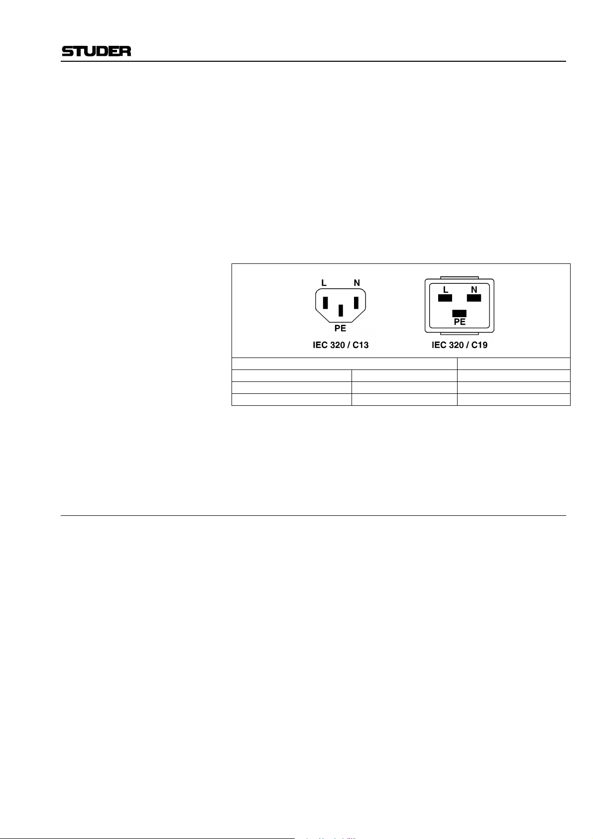
Should the equipment be delivered without a matching mains cable, the
latter has to be prepared by a trained person using the attached female plug
(IEC320/C13 or IEC320/C19) with respect to the applicable regulations in
your country.
Before connecting the equipment to the AC power outlet, check that the
local line voltage matches the equipment rating (voltage, frequency) within
the admissible tolerance. The equipment fuses must be rated in accordance
with the specifications on the equipment.
Equipment supplied with a 3-pole appliance inlet (protection conforming to
class I equipment) must be connected to a 3-pole AC power outlet so that
the equipment cabinet is connected to the protective earth.
For information on mains cable strain relief please refer to Appendix 2.
Female plug (IEC320), front-side view: National American Standard:
L (Live) Brown Black
N (Neutral) Blue White
PE (Protective Earth Green/Yellow Green
Class III Equipment (Battery Operation up to 60 VDC)
Equipment of this protection class must be earthed using the provided earth
terminal, if one or more external signals are connected to the unit (see explanation at the beginning of this paragraph).
B4 Electromagnetic Compatibility (EMC)
The unit conforms to the protection requirements relevant to electromagnetic phenomena that are listed in the guidelines 89/336/EC and FCC, part
15.
• The electromagnetic interference generated by the unit is limited in such
a way that other equipment and systems can be operated normally.
• The unit is adequately protected against electromagnetic interference so
that it can operate properly.
The unit has been tested and conforms to the EMC standards of the specified electromagnetic environment, as listed in the following declaration.
The limits of these standards ensure protection of the environment and corresponding noise immunity of the equipment with appropriate probability.
However, a professional installation and integration within the system are
imperative prerequisites for operation without EMC problems.
For this purpose, the following measures must be followed:
• Install the equipment in accordance with the operating instructions. Use
the supplied accessories.
• In the system and in the vicinity where the equipment is installed, use
only components (systems, equipment) that also fulfill the EMC standards for the given environment.
• Use a system grounding concept that satisfies the safety requirements
(class I equipment must be connected with a protective ground conduc-
Date printed: 26.04.04 III
Page 6
Installation/Maintenance/ESD
tor) and that also takes into consideration the EMC requirements. When
deciding between radial, surface, or combined grounding, the advantages and disadvantages should be carefully evaluated in each case.
• Use shielded cables where shielding is specified. The connection of the
shield to the corresponding connector terminal or housing should have a
large surface and be corrosion-proof. Please note that a cable shield
connected only single-ended can act as a transmitting or receiving antenna within the corresponding frequency range.
• Avoid ground loops or reduce their adverse effects by keeping the loop
surface as small as possible, and reduce the noise current flowing
through the loop by inserting an additional impedance (e.g. commonmode choke).
• Reduce electrostatic discharge (ESD) of persons by installing an appropriate floor covering (e.g. a carpet with permanent electrostatic filaments) and by keeping the relative humidity above 30%. Further measures (e.g. conducting floor) are usually unnecessary and only suitable if
used together with corresponding personal equipment.
• When using equipment with touch-sensitive operator controls, please
take care that the surrounding building structure allows for sufficient
capacitive coupling of the operator. This coupling can be improved by
an additional, conducting surface in the operator’s area, connected to the
equipment housing (e.g. metal foil underneath the floor covering, carpet
with conductive backing).
C Maintenance
All air vents and openings for operating elements (faders, rotary knobs)
must be checked on a regular basis, and cleaned in case of dust accumulation. For cleaning, a soft paint-brush or a vacuum cleaner is recommended.
Cleaning the surfaces of the unit is performed with a soft, dry cloth or a
soft brush.
Persistent contamination can be treated with a cloth that is slightly humidified with a mild cleaning solution (soap-suds).
For cleaning display windows, commercially available computer/TV
screen cleaners are suited. Use only a slightly damp (never wet) cloth.
Never use any solvents for cleaning the exterior of the unit! Liquids must
never be sprayed or poured on directly!
For equipment-specific maintenance information please refer to the corresponding chapter in the Operating and Service Instructions manuals.
D Electrostatic Discharge during Maintenance and Repair
Caution: Observe the precautions for handling devices sensitive to electrostatic dis-
charge!
Many semiconductor components are sensitive to electrostatic discharge
(ESD). The life-span of assemblies containing such components can be
drastically reduced by improper handling during maintenance and repair
work. Please observe the following rules when handling ESD sensitive
components:
• ESD sensitive components should only be stored and transported in the
packing material specifically provided for this purpose.
• When performing a repair by replacing complete assemblies, the removed assembly must be sent back to the supplier in the same packing
IV Date printed: 26.04.04
Page 7

E Repair
ESD/Repair
material in which the replacement assembly was shipped. If this should
not be the case, any claim for a possible refund will be null and void.
• Unpacked ESD sensitive components should only be handled in ESD
protected areas (EPA, e.g. area for field service, repair or service bench)
and only be touched by persons who wear a wristlet that is connected to
the ground potential of the repair or service bench by a series resistor.
The equipment to be repaired or serviced as well as all tools and electrically semi-conducting work, storage, and floor mats should also be connected to this ground potential.
• The terminals of ESD sensitive components must not come in uncontrolled contact with electrostatically chargeable (voltage puncture) or
metallic surfaces (discharge shock hazard).
• To prevent undefined transient stress of the components and possible
damage due to inadmissible voltages or compensation currents, electrical connections should only be established or separated when the
equipment is switched off and after any capacitor charges have decayed.
Removal of housing parts, shields, etc. exposes energized parts. For this
reason the following precautions must be observed:
• Maintenance may only be performed by trained personnel in accordance
with the applicable regulations.
• The equipment must be switched off and disconnected from the AC
power outlet before any housing parts are removed.
• Even if the equipment is disconnected from the power outlet, parts with
hazardous charges (e.g. capacitors, picture tubes) must not be touched
until they have been properly discharged. Do not touch hot components
(power semiconductors, heat sinks, etc.) before they have cooled off.
• If maintenance is performed on a unit that is opened and switched on, no
un-insulated circuit components and metallic semiconductor housings
must be touched, neither with your bare hands nor with un-insulated
tools.
Certain components pose additional hazards:
• Explosion hazard from lithium batteries, electrolytic capacitors and
power semiconductors (watch the component’s polarity. Do not short
battery terminals. Replace batteries only by the same type).
• Implosion hazard from evacuated display units.
• Radiation hazard from laser units (non-ionizing), picture tubes (ionizing).
• Caustic effect of display units (LCD) and components containing liquid
electrolyte.
Such components should only be handled by trained personnel who are
properly protected (e.g. safety goggles, gloves).
Date printed: 26.04.04 V
Page 8
Repair/Disposal
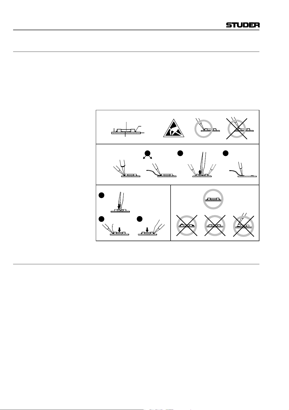
E1 SMD Components
Studer does not keep any commercially available SMD components in
stock. For repair the corresponding devices should be purchased locally.
The specifications of special components can be found in the service manual.
SMD components should only be replaced by skilled specialists using appropriate tools. No warranty claims will be accepted for circuit boards that
have been damaged. Proper and improper SMD soldering joints are illustrated below.
Copper
Track
Dismounting
Soldering
Iron
Mounting
1
Solder
2
Ø 0.5...0.8 mm
SMD
Component
Solder
Adhesive
Desoldering
Iron
Desolder
Wick
3
Heating Time < 3 s per Side
PCB
1
Soldering Iron
32
Desolder
Wick
Heat and Remove Cleaning
Examples
F Disposal
Disposal of Packing Materials The packing materials have been selected with environmental and disposal
issues in mind. All packing material can be recycled. Recycling packing
saves raw materials and reduces the volume of waste.
If you need to dispose of the transport packing materials, please try to use
recyclable means.
Disposal of Used Equipment Used equipment contains valuable raw materials as well as materials that
must be disposed of professionally. Please return your used equipment via
an authorized specialist dealer or via the public waste disposal system, ensuring any material that can be recycled is.
Please take care that your used equipment cannot be abused. To avoid
abuse, delete sensitive data from any data storage media. After having disconnected your used equipment from the mains supply, make sure that the
mains connector and the mains cable are made useless.
VI Date printed: 26.04.04
Page 9

G Declarations of Conformity
G1 Class A Equipment - FCC Notice
This equipment has been tested and found to comply with the limits for a
Class A digital device, pursuant to Part 15 of the FCC Rules. These limits
are designed to provide a reasonable protection against harmful interference when the equipment is operated in a commercial environment. This
equipment generates, uses, and can radiate radio frequency energy and, if
not installed and used in accordance with the instruction manual, may
cause harmful interference to radio communications. Operation of this
equipment in a residential area is likely to cause harmful interference, in
which case the user will be required to correct the interference at his own
expense.
Caution: Any changes or modifications not expressly approved by the manufacturer
could void the user's authority to operate the equipment. Also refer to relevant information in this manual.
Conformity
G2 CE Declaration of Conformity
We,
Studer Professional Audio GmbH,
CH-8105 Regensdorf,
declare under our sole responsibility that the product
Studer OnAir 2000M2 Modulo, Digital Mixing System
(starting with serial no. 1001)
to which this declaration relates, according to following regulations of EU
directives and amendments
• Low Voltage (LVD):
73/23/EEC + 93/68/EEC
• Electromagnetic Compatibility (EMC):
89/336/EEC + 92/31/EEC + 93/68/EEC
is in conformity with the following standards or other normative documents:
• Safety:
EN 60950:2000 (Class I equipment)
• Safety of laser products:
EN 60825-1:1994 + A11 + A2, EN60825-2:2000
• EMC:
EN 55103-1/-2:1996, electromagnetic environments E2 and E4.
Regensdorf, November 5, 2002
B. Hochstrasser, President P. Fiala, Manager QA
Date printed: 26.04.04 VII
Page 10

Appendix
Appendix 1: Air Temperature and Humidity
General
Normal operation of the unit or system is warranted under the following
ambient conditions defined by EN 60721-3-3, set IE32, value 3K3.
This standard consists of an extensive catalogue of parameters, the most
important of which are: ambient temperature +5...+40 °C, relative humidity
5...85% (i.e., no formation of condensation or ice); absolute humidity
1...25 g/m³; rate of temperature change < 0.5 °C/min. These parameters are
dealt with in the following paragraphs.
Under these conditions the unit or system starts and works without any
problem. Beyond these specifications, possible problems are described in
the following paragraphs.
Ambient Temperature
Units and systems by Studer are generally designed for an ambient temperature range (i.e. temperature of the incoming air) of +5...+40 °C. When
rack mounting the units, the intended air flow and herewith adequate cooling must be provided. The following facts must be considered:
• The admissible ambient temperature range for operation of the semiconductor components is 0 °C to +70 °C (commercial temperature range
for operation).
• The air flow through the installation must provide that the outgoing air
is always cooler than 70 °C.
• Average heat increase of the cooling air shall be 20 K, allowing for an
additional maximum 10 K increase at the hot components.
• In order to dissipate 1 kW with this admissible average heat increase, an
air flow of 2.65 m³/min is required.
Example: A rack dissipating P = 800 W requires an air flow of 0.8 * 2.65 m³/min
which corresponds to 2.12 m³/min.
• If the cooling function of the installation must be monitored (e.g. for fan
failure or illumination with spot lamps), the outgoing air temperature
must be measured directly above the modules at several places within
the rack. The trigger temperature of the sensors should be 65 to 70 °C.
Frost and Dew
The unsealed system parts (connector areas and semiconductor pins) allow
for a minute formation of ice or frost. However, formation of dew visible
with the naked eye will already lead to malfunctions. In practice, reliable
operation can be expected in a temperature range above –15 °C, if the following general rule is considered for putting the cold system into operation:
If the air within the system is cooled down, the relative humidity rises. If it
reaches 100%, condensation will arise, usually in the boundary layer between the air and a cooler surface, together with formation of ice or dew at
sensitive areas of the system (contacts, IC pins, etc.). Once internal condensation occurs, trouble-free operation cannot be guaranteed, independent
of temperature.
VIII Date printed: 26.04.04
Page 11

Appendix
Before putting into operation, the system must be checked for internal formation of condensation or ice. Only with a minute formation of ice, direct
evaporation (sublimation) may be expected; otherwise the system must be
heated and dried while switched off.
A system without visible internal formation of ice or condensation should
be heated up with its own heat dissipation, as homogeneously (and subsequently as slow) as possible; the ambient temperature should then always
be lower than the one of the outgoing air.
If it is absolutely necessary to operate the cold system immediately within
warm ambient air, this air must be dehydrated. In such a case, the absolute
humidity must be so low that the relative humidity, related to the coldest
system surface, always remains below 100%.
Ensure that the enclosed air is as dry as possible when powering off (i.e.
before switching off in winter, aerate the room with cold, dry air, and remove humid objects as clothes from the room).
These relationships are visible from the following climatogram. For a controlled procedure, thermometer and hygrometer as well as a thermometer
within the system will be required.
Example 1: An OB-van having an internal temperature of 20 °C and relative humidity
of 40% is switched off in the evening. If temperature falls below +5 °C,
dew or ice will be forming.
Example 2: An OB-van is heated up in the morning with air of 20 °C and a relative
humidity of 40%. On all parts being cooler than +5 °C, dew or ice will be
forming.
Date printed: 26.04.04 IX
Page 12

Appendix
Appendix 2: Mains Connector Strain Relief
For anchoring connectors without a mechanical lock (e.g. IEC mains connectors), we recommend the following arrangement:
Procedure: The cable clamp shipped with your unit is auto-adhesive. For mounting
please follow the rules below:
• The surface to be adhered to must be clean, dry, and free from grease,
oil, or other contaminants. Recommended application temperature range
is 20...40 °C.
• Remove the plastic protective backing from the rear side of the clamp
and apply it firmly to the surface at the desired position. Allow as much
time as possible for curing. The bond continues to develop for as long as
24 hours.
• For improved stability, the clamp should be fixed with a screw. For this
purpose, a self-tapping screw and an M4 bolt and nut are included.
• Place the cable into the clamp as shown in the illustration above and
firmly press down the internal top cover until the cable is fixed.
X Date printed: 26.04.04
Page 13

Appendix 3: Software License
Use of the software is subject to the Studer Professional Audio Software
License Agreement set forth below. Using the software indicates your acceptance of this license agreement. If you do not accept these license terms,
you are not authorized to use this software.
Under the condition and within the scope of the following Terms and Conditions, Studer Professional Audio GmbH (hereinafter “Studer”) grants the
right to use programs developed by Studer as well as those of third parties
which have been installed by Studer on or within its products. References
to the license programs shall be references to the newest release of a license program installed at the Customer’s site.
Programs Covered by the Agreement
License Programs of Studer The following Terms and Conditions grant the right to use all programs of
Studer that are part of the System and/or its options at the time of its delivery to the Customer, as well as the installation software on the original data
disk and the accompanying documentation (“License Material”). In this
Agreement the word “Programs” shall have the meaning of programs and
data written in machine code.
Using the software indicates your acceptance of this license agreement. If
you do not accept these license terms, you are not authorized to use this
software.
Appendix
Programs of Third Parties Programs of third parties are all programs which constitute part of the
Right of Use
System and/or its options at the time of delivery to the Customer but have
not been developed by Studer. The following conditions are applicable to
programs of third parties:
• The right to use third parties’ programs is governed by the License
Agreement attached hereto (if applicable), which is an integral part of
this Agreement. The Customer shall sign any and all License Agreements for all further programs of third parties installed on the system.
The Customer shall be deemed to have received all License Agreements
upon delivery of the system and/or its options.
• Studer shall accept no responsibility or liability for, and gives no warranties (express or implied) as to the programs of third parties. The
Customer waives any and all claims versus Studer for any consequential
damages, which might occur due to defects of these programs.
Principle Studer grants the Customer the non-exclusive right to use the License Ma-
terial in one copy on the system and/or its options as laid down by the
Sales Agreement concluded between the parties and all Terms and Conditions which shall be deemed to form and be read and construed as part of
the Sales Agreement. This right is assignable according to the “Assignability” paragraph hereinafter.
Customized Configurations The Customer is not entitled to alter or develop further the License Mate-
rial except within the expressly permitted configuration possibilities given
by the software installed on the system or elsewhere. All altered programs,
including but not limited to the products altered within the permitted configuration possibilities, are covered by this License Agreement.
Date printed: 26.04.04 XI
Page 14

Appendix
Reverse Engineering Reverse engineering is only permitted with the express consent of Studer.
The consent of Studer can be obtained but is not limited to the case in
which the interface-software can not be provided by Studer. In any case
Studer has to be informed immediately upon complete or partial reverse
engineering.
Copying the License Material The Customer is entitled to make one copy of all or parts of the License
Material as is necessary for the use according to this Agreement, namely
for backup purposes. The Customer shall apply the copyright of Studer
found on the License Material onto all copies made by him. Records shall
be kept by the Customer regarding the amount of copies made and their
place of keeping. The responsibility for the original program and all copies
made lies with the Customer. Studer is entitled to check these records on
first request. Copies not needed anymore have to be destroyed immediately.
Disclosure of License Material The License Material is a business secret of Studer. The Customer shall not
hand out or in any way give access to parts or the complete License Material to third parties nor to publish any part of the License Material without
prior written consent of Studer. The Customer shall protect the License
Material and any copies made according to the paragraph above by appropriate defense measures against unauthorized access. This obligation of
non-disclosure is a perpetual obligation.
Third parties are entitled to have access to the License Material if they use
the License Material at the Customer’s site in compliance with this Agreement.
Under no circumstance are third parties entitled to have access to the installation software on the original data media. The Customer shall safeguard the original data media accordingly.
Assignability The rights granted to the Customer according to this License Agreement
shall only be assignable to a third party together with the transfer of the
system and/or its options and after the prior written consent of Studer.
Rights to License Material
With the exception of the right of use granted by this License Agreement
all proprietary rights to the License Material, especially the ownership and
the intellectual property rights (such as but not limited to patents and copyright) remain with Studer even if alterations, customized changes or
amendments have been made to the License Material.
Studer’s proprietary rights are acknowledged by the Customer. The Customer shall undertake no infringements and make no claims of any patent,
registered design, copyright, trade mark or trade name, or other intellectual
property right.
Warranty, Disclaimer, and Liability
For all issues not covered herewithin, please refer to the “General Terms
and Conditions of Sale and Delivery” that are part of the sales contract.
XII Date printed: 26.04.04
Page 15

OnAir 2000M2 Modulo Digital Mixing Console
CONTENTS
1 Introduction....................................................................................................................................................................1-1
2 General............................................................................................................................................................................ 2-1
2.1 Utilization for the Purpose Intended......................................................................................................................... 2-1
2.2 First Steps ................................................................................................................................................................. 2-1
2.2.1 Unpacking and Inspection ................................................................................................................................ 2-1
2.2.2 Installation ........................................................................................................................................................ 2-1
2.2.3 Adjustments, Repair.......................................................................................................................................... 2-2
3 Module Information ....................................................................................................................................................... 3-1
3.1 Central Module......................................................................................................................................................... 3-1
3.2 Fader Module............................................................................................................................................................3-2
3.3 Meter Module ........................................................................................................................................................... 3-2
3.4 19” Processor Frame................................................................................................................................................. 3-3
3.5 Optional Input Module Extension.............................................................................................................................3-4
3.6 Optional Redundant Power Supply........................................................................................................................... 3-4
4 Wiring Information........................................................................................................................................................ 4-1
4.1 Internal Wiring .........................................................................................................................................................4-1
4.2 External Wiring ........................................................................................................................................................ 4-2
4.3 Connector Pin Assignments...................................................................................................................................... 4-3
5 Diagrams ......................................................................................................................................................................... 5-1
Date printed: 11.12.02 SW V 4.0 Contents 0-1
Page 16

1 INTRODUCTION
OnAir 2000M2 Modulo Digital Mixing Console
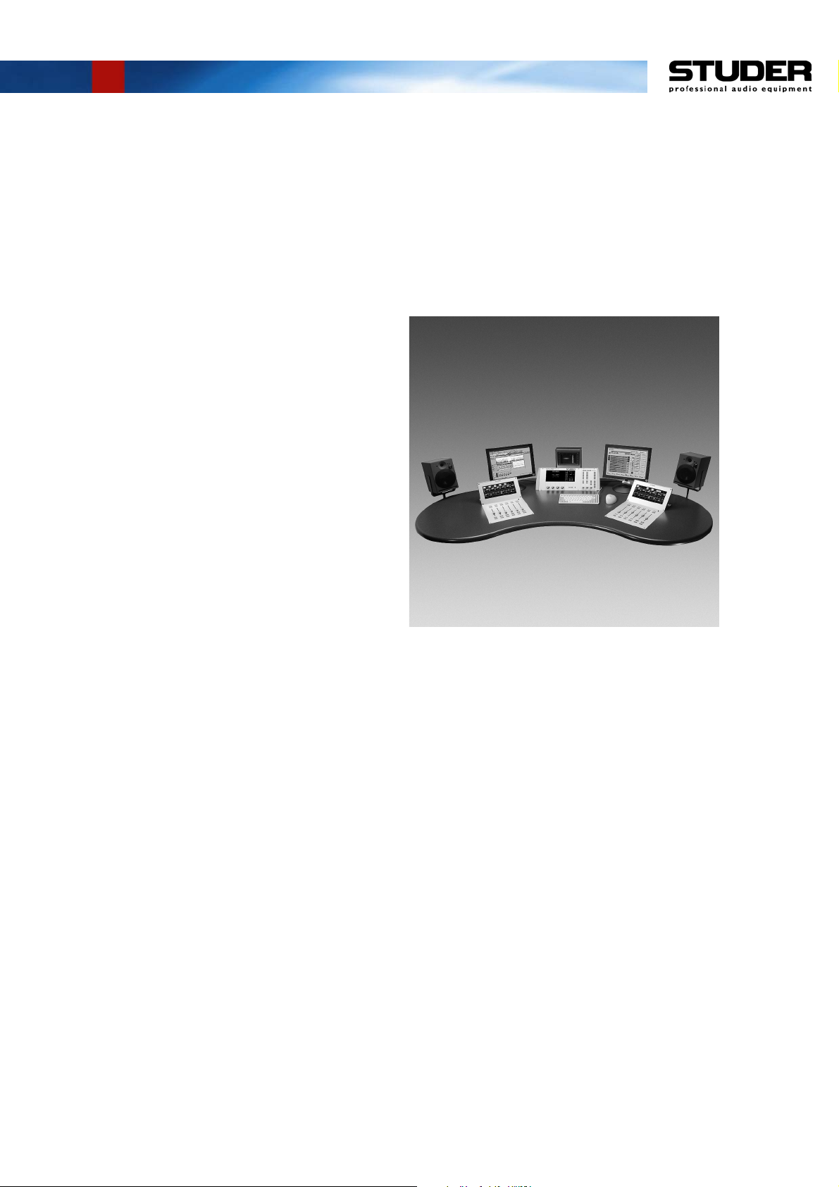
The OnAir 2000M2 Modulo is virtually identical with Studer’s wellknown OnAir 2000M2 digital mixing console, except that it adds a new
degree in flexibility due to its modular surface design. This allows the studio designer to arrange the desk components to the user’s convenience,
and to distance the I/Os and processor from the desk if desired.
The technical specifications, configurations and options as well as operation are the same as with the standard Studer OnAir 2000M2 digital mixing console. For operation and/or service, please consult the respective
manuals. An OnAir 2000M2 operating manual is shipped together with
each OnAir 2000M2 Modulo console.
This manual describes only the differences to the standard Studer OnAir
2000M2 console.
The picture above shows a typical OnAir 2000M2 Modulo installation
with optional components (RTW vectorscope, Studer DigiMedia, Studer
A1 active speakers, custom table).
Date printed: 11.12.02 SW V 4.0 Intro 1-1
Page 17

OnAir 2000M2 Modulo Digital Mixing Console
2 GENERAL
2.1 Utilization for the Purpose Intended
The OnAir 2000M2 Modulo mixing console is intended for professional
use.
It is presumed that the unit is operated only by trained personnel. Servicing
is reserved to skilled technicians.
The electrical connections may be connected only to the voltages and signals designated in this manual or in the respective OnAir 2000M2 manuals.
2.2 First Steps
2.2.1 Unpacking and Inspection
Your new mixing console is shipped in a special packing which protects
the units against mechanical shock during transit. Care should be exercised
when unpacking so that the surfaces do not get marred.
Check the condition of the equipment for signs of shipping damage. If
there should be any complaints you should immediately notify the forwarding agent and your nearest Studer distributor.
Please retain the original packing material because it offers the best protection in case your equipment ever needs to be transported.
2.2.2 Installation
Primary Voltage: The power supply unit is auto-ranging; it can be used for mains voltages in
General Precautions: Do not use the unit in conditions of excessive heat or cold, near any source
Cleaning: Do not use any liquids to clean the exterior of the unit. A soft, dry cloth or
Power Connection: The attached female IEC 320/C13 mains cable socket has to be connected
a range of 100 to 240 VAC, 50 to 60 Hz.
of moisture, in excessively humid environments, or in positions where it is
likely to be subjected to vibration or dust. The ambient temperature range
for normal operation of the unit is +5...+40° C.
When installing the processor frame, free air flow has to be assured. If the
rack is closed at the top and/or the bottom, 1U air vent panels
(1.950.693.01) have to be installed above and/or below the processor
frame; refer to the drawing in chapter 3.4 for details.
brush will usually do.
For cleaning the touch-screen display windows, most of the commercially
available window or computer/TV screen cleaners are suited. Use only a
slightly damp (never wet) cloth. Never use any solvent!
to an appropriate mains cable by a trained technician, respecting your local
regulations. Refer to the “Installation, Operation, and Waste Disposal”
section at the beginning of this manual.
Date printed: 11.12.02 SW V 4.0 General 2-1
Page 18

OnAir 2000M2 Modulo Digital Mixing Console
Earthing: This equipment must be earthed, due to the mains input filter network be-
ing connected to the mains earth.
Some consideration should be given to the earthing arrangement of the
system; the processor frame must be in its center, i.e. in the system's star
point.
The processor frame is earthed to the mains earth via the power supply.
Ground loops may occur where signal processing equipment, patched to
the processor frame, has its signal earth commoned to the equipment chassis.
Please note that for safety and EMC reasons, the frames may be operated only one on top of the other, with a tight ground connection between them – installation of the different racks e.g. installed separately
or side-by-side is strictly prohibited.
Meter Module Cables: Please note that the connecting cables between the electronics rack and the
meter module (4 × 25 pin D-type) must not be interchanged. The connectors and the respective receptacles are coded; however, care is required
nevertheless when establishing these connections.
If a custom meter bridge is installed, attention has to be paid to proper
connection, otherwise damage to the units may occur.
2.2.3 Adjustments, Repair
Danger: All internal adjustments as well as repair work on this product must be
performed by trained technicians!
Replacing the Supply Unit: The primary fuse is located inside the power supply module and cannot be
changed. In case of failure, the complete power supply unit must be replaced. Please ask your nearest Studer representative.
2-2 General SW V 4.0 Date printed: 11.12.02
Page 19

3 MODULE INFORMATION
3.1 Central Module
The Central Module consists of the central touch-screen with four
rotary encoders beneath, and the monitoring/talkback/signaling
section. It can be placed on the desk as a standalone unit, or installed in a 19” rack, e.g. in an OB van (190 mm height). If desired, the meters can optionally be included with the Central
Module to provide all common functions in a compact housing.
OnAir 2000M2 Modulo Digital Mixing Console
154
450.4 +1/–0
452 (cut)
30 (min.)
For mounting, a simple rectangular cutout in the table is sufficient; there are two methods (see detail below). First attach 2
brackets [1] to the Central Module with two screws [A] each.
· Recommended method (table thickness min. 30 mm): Insert
the unit into the cutout, and fix it with a clamp [2] on either
side (2 screws [B] each)
· Alternate method: Remove the side panels; for this purpose,
the front panels must be removed. Insert the unit into the cutout, and fix it on either side to the table with two screws [C].
Reinstall the side panels and the front panel.
52°
74
76 (cut)
C
CC
1
A
AA
2
B
BB
Date printed: 11.12.02 SW V 4.0 Module Information 3-1
Page 20

OnAir 2000M2 Modulo Digital Mixing Console
3.2 Fader Module
The Fader Module includes six channel faders with ON, OFF and PFL
keys, an overload indicator per channel, and the channel touch-screen for
instant overview on all relevant channel parameter settings. The modules
can be placed separately according to good ergonomic practice, or joined
together in line according to the customer’s needs and the available space.
The console can be equipped with one up to four Fader Modules (6 to 24
channel faders).
For mounting, a simple rectangular cutout is sufficient. Two mounting
brackets [A] are shipped with every unit. Attach them to the inside of the
cutout. Then remove the front panel and rear cover from the module and
insert the module into the table. Attach the module with two screws to
each bracket and reinstall the front panel.
3.5 ... 4
3.3 Meter Module
A
286 (cut)
285 +0.5/–0
60
410 +0.5/–0
411 (cut)
The Meter Module can be equipped to customer specifications with various meters from RTW, NTP, DKAudio, or Studer, including an audio
vectorscope. The Meter Module for 190 mm units is available in four sizes
providing 4, 8, 12, or 16 slots and can be freely placed in the working environment. External stand-alone audio vectorscopes can also be used. The
meters can be included with the Central Module to provide all common
functions in a compact housing.
Please note: The connecting cables between the electronics rack and the
meter module (4 × 25 pin D-type) must not be interchanged. The connectors and the respective receptacles are coded, however care is required
nevertheless when establishing these connections.
52°
137
3-2 Module Information SW V 4.0 Date printed: 11.12.02
Page 21

3.4 19” Processor Frame
The complete electronics are housed in a 19” frame with 380 mm depth.
The 19” main frame (8 U, 354.8 mm) contains the DSP and the control
CPU, the output modules, the power supply and the monitoring module.
Up to two 19” I/O frames (4U, 177 mm each) can be equipped each with
either 6 or 12 input modules, giving a maximum of 24 input modules with
a maximum of 64 input signals.
When installing the processor frame, free air flow from bottom to top must
be assured. If the rack is closed at the bottom and/or the top, 1U air vent
panels (1.950.693.01) must be installed below and/or above the frame.
Please note that for safety and EMC reasons, the frames may be operated only one on top of the other, with a tight ground connection between them – installation of the different racks e.g. installed separately
or side-by-side is strictly prohibited.
The drawing below shows a fully-equipped rack with two 19” I/O frames
for a 24-channel console, together with the required air vent panels on
bottom and top.
OnAir 2000M2 Modulo Digital Mixing Console
355.6 (8U)
CONTROL RACK
177 (4U)
INPUT RACK 12CH
177 (4U)
INPUT RACK 12CH
44.4 (1U)
Air Vent Panel (passive)
OnAir2000 Modulo
OnAir2000 Modulo
OnAir2000 Modulo
Air Vent Panel (passive)
482.6
Front View
Connector Panel
Air Vent Panel (passive)
Air Vent Panel (passive)
380
480
Left View
Air Vent Panel (passive)
Air Vent Panel (passive)
80
440
Rear View
Date printed: 11.12.02 SW V 4.0 Module Information 3-3
Page 22

OnAir 2000M2 Modulo Digital Mixing Console
3.5 Optional Input Module Extension
Similar to the standard OnAir 2000M2, the Modulo can be equipped with
the Input Module Extension Box. The Extension Box allows for a higher
number of inputs than the number of faders, e.g. a six-fader console may
be equipped with 6, 12, 18 or max. 24 input modules, with a maximum of
64 input signals. The Extension Box becomes useful namely if space is restricted, but more input modules than faders need to be installed. In this
case, the additionally required input modules can be placed aside the rack
in the Input Module Extension Box instead of in an I/O frame, thus reducing the total rack height.
3.6 Optional Redundant Power Supply
The power supply of the Studer OnAir 2000M2 Modulo normally
is located within the 19” processor frame. Optionally, fully redundant power supplies are available; they are externally housed in
two 19”/2 U frames. Primary and secondary converters, mains inlets, power distribution, and secondary voltage connections to the
rack are fully redundant.
3-4 Module Information SW V 4.0 Date printed: 11.12.02
Page 23

4 WIRING INFORMATION
4.1 Internal Wiring
OnAir 2000M2 Modulo Digital Mixing Console
Fader Module (up to 4)
Display
(Input Modules)
Flex
cables
n
i
p
6
P1
P2
1
P5
P6
Channel Front Board
1.942.210
40pin
Rem. Slave Module
1.942.282
Rem. Master Module
1.942.280
P1
P2
40pin
Input Modules
1 2 3 4 5 6
P4
Display
Illumination
P2
P1
P3
100...240 V
Meter Module
Meter 1
e.g.
1.913.111
1.913.112
AC
2 × Power Supply
89.20.2011
100..240 V
AC
100..240 V
AC
Power Supply
1.942.105
P1 P2 P3 P4 P5 P6
40pin
Correlator
1.913.100
1.913.109
24 V
24 V
e.g.
Meter 2
e.g.
1.913.111
1.913.112
19" Electronics Rack
DC
DC
1 2 3 4 5 6 7 8 9 10 11
Output Modules
64pin
Central Module
P3
Ctrl. Front Board I
1.942.610
P7 P6 P5 P4
16pin
Ctrl. Front Board III
1.942.112
16pin
P2
P1
P1
Display
illumin-
ation
Flex
cables
Ctrl. Front Board II
20pin
64/40pin
P2
P1
Rem. Slave Module
1.942.282
Rem. Master Module
64pin
P2
Spkr
Phones
r
t
2
e
u
l
8
l
O
1
o
.
r
r
2
t
o
4
t
n
i
9
o
.
64pin
P1 P2 P1 P2 P1 P2 P1 P2
n
1
C
o
.
M
n
3
o
R
P
M
C
Display
(Center Screen)
1.942.111
P2
1.942.280
P1
16pin
r
r
2
3
o
o
3
3
t
t
i
i
1
1
.
.
n
n
2
2
o
o
4
4
M
9
9
.
1
M
.
o
1
R
i
d
C
u
t
S
P3
1
3
1
.
2
4
9
.
1
(Option)
TB Mic Inp.
1.942.219
(Option)
Serial Interface
40pin
16pin
P1 (IMB1)
P2 (IMB2)
P3 (IMB3)
P4 (IMB4)
16pin
P19 P26 P27
DSP Board
1.942.102
64pin
16pin
P71
16pin
P72
16pin
P73P70
P1
P2
ME1LP3ME1R
Level Meter Interface
1.942.113
ME2L
CORR
P4
P6
P5
ME2R
P7
RS232/RS422
1.942.145
P7
P4
P9
P11
P16 P18
(Options)
Tel. Hybrid IF
1.942.140
Clock Sync IF
1.942.135
Time Sync IF
1.942.150
20pin
P3
LCD
1...6
P5
LCD
7...12
P8
LCD
LCD
13...18
19...24
Controller Board
P10
1.942.601
P13
Service Terminal
Date printed: 11.12.02 SW V 4.0 Wiring Information 4-1
Page 24

OnAir 2000M2 Modulo Digital Mixing Console
4.2 External Wiring
1
2
External
TB Mic
(optional)
1
[1] Connecting cables from the Processor Frame to the Fader Module(s) and
1
1
to the Central Module. These cables are available in different standard
lengths. For this reason, they have to be ordered separately, depending on
the current application. Their length is determined during discussion with
Studer’s quotation engineers.
Cable Length Order No. (for one cable)
2.5 m 1.942.400.25
10 m 1.942.400.26
20 m 1.942.400.27
1
[2] Connecting cable set from the Processor Frame to the Meter Module; not
available in standard configurations, as the metering is completely depending on the customer’s specification. They are individually defined
during the quotation stage.
Please note that the connecting cables between the electronics rack and the
meter module (up to 4 × 25 pin D-type) must not be interchanged. The
connectors and the respective receptacles are coded; however, care is required nevertheless while setting up these connections.
4-2 Wiring Information SW V 4.0 Date printed: 11.12.02
Page 25

4.3 Connector Pin Assignments
• FADER MODULE and CENTER PANEL connectors, female, on the
Processor Frame (D37f)
• Connectors, male, at the rear of the Fader Module and the Center Panel
(D37m)
Pin Signal Pin Signal
1 +15 V 20 AGND
2 –15 V 21 _PD_I
3GND 22GND
4_INT_X 23VCC
5 VCC 24 P_RES_X
6 +24 V 25 +24 V
7 RXD_X + 26 RXD_X –
8 TXD_X + 27 TXD_X –
9 SCLK_X + 28 SCLK_X –
10 GND 29 GND
11 FLM_X + 30 FLM_X –
12 LP_X + 31 LP_X –
13 CP_X + 32 CP_X –
14 M_X + 33 M_X –
15 LCD0_X + 34 LCD0_X –
16 LCD1_X + 35 LCD1_X –
17 LCD2_X + 36 LCD2_X –
18 LCD3_X + 37 LCD3_X –
19 –24 V
OnAir 2000M2 Modulo Digital Mixing Console
For the following four connectors, only the pin assignment on the Processor Frame can be given; the pin assignment on the other end of the connecting cables completely depends on the individual customer’s layout.
DIGITAL METER / PFL (D25f)
Pin Signal Pin Signal
1 GND 14 AES_OUT1+
2 AES_OUT1– 15
3 GND 16 AES_OUT2+
4 AES_OUT2– 17
518DGND
6 +24V 19 DGND
7 +24V 20
821
9 HP_GND 22 HP_LEFT
10 HP_RIGHT 23
11 24 LS–
12 LS+ 25 KEY
13
Date printed: 11.12.02 SW V 4.0 Wiring Information 4-3
Page 26

OnAir 2000M2 Modulo Digital Mixing Console
ANALOG METER 1 (D25f)
Pin Signal Pin Signal
1 KEY 14 +15V
215DGND
3 CH1+ 16 –15V
4 CH1– 17 +5V
5 –24V (ext.) 18 DGND
619
720
821
9 +15V 22
10 DGND 23 CH2+
11 –15V 24 CH2–
12 +5V 25 –24V (ext.)
13 DGND
ANALOG METER 2 (D25f)
Pin Signal Pin Signal
1 KEY 14 +15V
215DGND
3 CH3+ 16 –15V
4 CH3– 17 +5V
5 –24V (ext.) 18 DGND
619
720
821
9 +15V 22
10 DGND 23 CH4+
11 –15V 24 CH4–
12 +5V 25 –24V (ext.)
13 DGND
CORRELATOR (D25f)
Pin Signal Pin Signal
1 CH2– 14 CH2+
2 CH3+ 15 CH1–
3 CH3– 16 CH1+
4 CH4+ 17 +15V
5 CH4– 18 DGND
6 19 –15V
720+5V
8 –24V (ext.) 21 DGND
922
10 23
11 24
12 25
13 KEY
4-4 Wiring Information SW V 4.0 Date printed: 11.12.02
Page 27

5 DIAGRAMS
OnAir 2000M2 Modulo Digital Mixing Console
Not e : As all OnAir 2000M2 Modulo electronics assemblies are identical with
the ones of the standard OnAir 2000M2 (with two exceptions), please refer for servicing to the OnAir 2000M2 Service Instructions Manual (Order No. 10.27.4521).
Information on the two assemblies that are used only for the OnAir
2000M2 Modulo is given on the following pages.
Remote Master Module 1.942.280.00
Remote Slave Module 1.942.282.00
Date printed: 11.12.02 SW V 4.0 Diagrams 5-1
Page 28

Remote Master Module 1.942.280.00 ( 0)
OnAir 2000M2 Modulo Digital Mixing Console
Date printed: 11.12.02 SW V 4.0 Diagrams 5-3
Page 29

OnAir 2000M2 Modulo Digital Mixing Console
Remote Master Module 1.942.280.00 ( 0)
Remote Master Module 1.942.280.00 ( 1)
Part No. Qty. Type/Val. DescriptionPos.Idx. Part No. Qty. Type/Val. DescriptionPos.Idx.
C 1 59.22.5220 22u EL 25V 20% RM50
C 2 59.06.0104 100n PETP, 63V, 10%, RM50
C 3 59.06.0104 100n PETP, 63V, 10%, RM50
C 4 59.06.0104 100n PETP, 63V, 10%, RM50
C 5 59.06.0104 100n PETP, 63V, 10%, RM50
C 6 59.06.0104 100n PETP, 63V, 10%, RM50
C 7 59.32.1101 100p CER 10%, 400V0
C 8 59.32.1101 100p CER 10%, 400V0
C 9 59.06.0104 100n PETP, 63V, 10%, RM50
IC 1 50.15.0127 34C87 IC DS 34 C 87 TN, MC34C87P ,A0
IC 2 50.15.0127 34C87 IC DS 34 C 87 TN, MC34C87P ,A0
IC 3 50.15.0127 34C87 IC DS 34 C 87 TN, MC34C87P ,A0
IC 4 50.05.0283 LM393 Dual Comparator0
IC 5 50.17.1541 74HC541 Octal bus buffer0
IC 6 50.15.0114 9637 Dual diff Line Receiver0
MP 1 1.942.280.11 REMOTE MASTER PCB0 1 pce
MP 2 43.01.0108 Label ESE-WARNSCHILD0 1 pce
MP 3 1.942.280.10 NR.ETIKETTE0 1 pce
MP 4 1.942.281.01 BLENDE REMOTE MODULE0 1 pce
MP 5 24.16.2030 3.2/6.0 Fächerscheibe Form A0 2 pcs
MP 6 21.53.0353 M3*5 Z-Schraube Inbus Zn gb chr0 2 pcs
MP 7 24.16.2030 3.2/6.0 Fächerscheibe Form A0 2 pcs
MP 8 54.13.0081 4.85mm Bolzen UNC 4-400 2 pcs
P 1 54.14.2056 64p Stecker gerade Au0
P 2 54.14.2054 40p Stecker gerade Au0
P 3 54.14.2002 16p 1/20" Au, gerade, ohne Verrieg0
P 4 54.13.0074 37p D-Sub, PCB, Winkel0
R 1 57.92.7013 0.5A PTC 60V0
R 2 57.92.7013 0.5A PTC 60V0
R 3 57.92.7015 1.1A PTC 50V0
R 4 57.11.3101 100R MF, 1%, 02070
R 5 57.11.3121 120R MF, 1%, 02070
R 6 57.11.3102 1k0 MF, 1%, 02070
R 7 57.11.3331 330R MF, 1%, 02070
R 8 not used 330R MF, 1%, 02071
R 9 57.11.3102 1k0 MF, 1%, 02070
R 10 57.11.3101 100R MF, 1%, 02070
R 11 57.11.3220 22R MF, 1%, 02070
R 12 57.11.3220 22R MF, 1%, 02070
R 13 57.11.3101 100R MF, 1%, 02070
R 14 57.11.3472 4k7 MF, 1%, 02070
R 15 57.11.3472 4k7 MF, 1%, 02070
R 16 57.11.3220 22R MF, 1%, 02070
R 17 57.11.3220 22R MF, 1%, 02070
R 18 57.11.3220 22R MF, 1%, 02070
R 19 57.11.3220 22R MF, 1%, 02070
R 20 57.11.3220 22R MF, 1%, 02070
R 21 57.11.3220 22R MF, 1%, 02070
R 22 57.11.3220 22R MF, 1%, 02070
R 23 57.11.3220 22R MF, 1%, 02070
R 24 57.11.3220 22R MF, 1%, 02070
R 25 57.11.3220 22R MF, 1%, 02070
R 26 57.11.3220 22R MF, 1%, 02070
R 27 57.11.3220 22R MF, 1%, 02070
R 28 57.11.3220 22R MF, 1%, 02070
R 29 57.11.3220 22R MF, 1%, 02070
R 30 57.11.3220 22R MF, 1%, 02070
R 31 57.11.3220 22R MF, 1%, 02070
R 32 57.11.3220 22R MF, 1%, 02070
R 33 57.11.3220 22R MF, 1%, 02070
R 34 57.11.3220 22R MF, 1%, 02070
R 35 57.11.3220 22R MF, 1%, 02070
R 36 57.11.3221 220R MF, 1%, 02070
R 37 57.11.3102 1k0 MF, 1%, 02070
R 38 57.11.3104 100k MF, 1%, 02070
R 39 57.11.3222 2k2 MF, 1%, 02070
R 40 57.11.3470 47R MF, 1%, 02070
R 41 57.11.3470 47R MF, 1%, 02070
R 42 57.11.3470 47R MF, 1%, 02070
R 43 57.11.3472 4k7 MF, 1%, 02070
R 44 57.11.3472 4k7 MF, 1%, 02070
R 45 57.11.3222 2k2 MF, 1%, 02070
R 46 57.11.3221 220R MF, 1%, 02070
R 47 57.11.3221 220R MF, 1%, 02070
R 48 57.11.3104 100k MF, 1%, 02070
R 49 57.11.3102 1k0 MF, 1%, 02070
R 50 57.11.3472 4k7 MF, 1%, 02070
RZ 1 57.88.4472 4k7 8*R Resistor-Netw 2% SIP90
XIC 1 53.03.0168 16p DIL 0.3", löt, gerade0
XIC 2 53.03.0168 16p DIL 0.3", löt, gerade0
XIC 3 53.03.0168 16p DIL 0.3", löt, gerade0
XIC 4 53.03.0166 8p DIL 0.3", löt, gerade0
XIC 5 53.03.0165 20p DIL 0.3", löt, gerade0
XIC 6 53.03.0166 8p DIL 0.3", löt, gerade0
(01) R8 not used
End of List
Page: 1 of 1
5-4 Diagrams SW V 4.0 Date printed: 11.12.02
Page 30

Remote Slave Module 1.942.282.00 ( 0)
OnAir 2000M2 Modulo Digital Mixing Console
Date printed: 11.12.02 SW V 4.0 Diagrams 5-5
Page 31

OnAir 2000M2 Modulo Digital Mixing Console
Remote Slave Module 1.942.282.00 ( 0)
Remote Slave Module 1.942.282.00 ( 0)
Part No. Qty. Type/Val. DescriptionPos.Idx. Part No. Qty. Type/Val. DescriptionPos.Idx.
C 1 59.60.3337 100n CER 50V, 10%, X7R, 08050 1 pce
C 2 59.60.3337 100n CER 50V, 10%, X7R, 08050 1 pce
C 3 59.60.3337 100n CER 50V, 10%, X7R, 08050 1 pce
C 4 59.60.3337 100n CER 50V, 10%, X7R, 08050 1 pce
C 5 59.60.3337 100n CER 50V, 10%, X7R, 08050 1 pce
C 6 59.68.0117 220u EL 35V, 10 *10.70 1 pce
C 7 59.60.3337 100n CER 50V, 10%, X7R, 08050 1 pce
C 8 59.60.3337 100n CER 50V, 10%, X7R, 08050 1 pce
C 9 59.60.3329 22n CER 50V, 10%, X7R, 08050 1 pce
C 10 59.60.2257 220p CER 50V, 5%, C0G, 06030 1 pce
C 11 59.68.0069 47u EL 16V, 6.3*5.70 1 pce
C 12 59.60.3337 100n CER 50V, 10%, X7R, 08050 1 pce
C 14 59.60.3337 100n CER 50V, 10%, X7R, 08050 1 pce
D 1 50.60.8103 SS14 1A 40V Schottky0 1 pce
IC 1 50.62.1541 74HC541 Octal buffer line driver/recei0 1 pce
IC 2 50.62.0463 DS34C86 4*RS 422 Line Receiver0 1 pce
IC 3 50.62.0463 DS34C86 4*RS 422 Line Receiver0 1 pce
IC 4 50.62.0463 DS34C86 4*RS 422 Line Receiver0 1 pce
IC 5 50.62.0464 DS34C87 4*RS 422 Line Driver0 1 pce
IC 6 50.61.2006 L5970D Step down switching regulator0 1 pce
L 1 62.60.0518 47uH SMD 2.5A0 1 pce
MP 1 1.942.282.11 REMOTE SLAVE MODULO PCB0 1 pce
MP 2 1.942.282.10 NR.ETIKETTE0 1 pce
MP 3 43.01.0108 Label ESE-WARNSCHILD0 1 pce
P 1 54.13.0079 37p D-Sub, PCB, Winkel0 1 pce
P 2 54.14.2054 40p Stecker gerade Au0 1 pce
P 3 54.14.2052 16p Stecker gerade Au0 1 pce
R 1 57.60.1101 100R MF, 1%, 0204, E240 1 pce
R 2 57.60.1101 100R MF, 1%, 0204, E240 1 pce
R 3 57.60.1101 100R MF, 1%, 0204, E240 1 pce
R 4 57.60.1101 100R MF, 1%, 0204, E240 1 pce
R 5 57.60.1101 100R MF, 1%, 0204, E240 1 pce
R 6 57.60.1101 100R MF, 1%, 0204, E240 1 pce
R 7 57.60.1101 100R MF, 1%, 0204, E240 1 pce
R 8 57.60.1101 100R MF, 1%, 0204, E240 1 pce
R 9 57.60.1101 100R MF, 1%, 0204, E240 1 pce
R 10 57.60.1101 100R MF, 1%, 0204, E240 1 pce
R 11 57.60.1101 100R MF, 1%, 0204, E240 1 pce
R 12 57.60.1101 100R MF, 1%, 0204, E240 1 pce
R 13 57.60.1101 100R MF, 1%, 0204, E240 1 pce
R 14 57.60.1101 100R MF, 1%, 0204, E240 1 pce
R 15 57.60.1101 100R MF, 1%, 0204, E240 1 pce
R 16 57.60.1101 100R MF, 1%, 0204, E240 1 pce
R 17 57.60.1470 47R MF, 1%, 0204, E240 1 pce
R 18 57.60.1470 47R MF, 1%, 0204, E240 1 pce
R 19 not used 330R MF, 1%, 0204, E240 1 pce
R 20 not used 1k0 MF, 1%, 0204, E240 1 pce
R 21 57.60.1470 47R MF, 1%, 0204, E240 1 pce
R 22 57.60.1470 47R MF, 1%, 0204, E240 1 pce
R 23 57.60.1470 47R MF, 1%, 0204, E240 1 pce
R 24 57.60.1470 47R MF, 1%, 0204, E240 1 pce
R 25 57.60.1470 47R MF, 1%, 0204, E240 1 pce
R 26 57.60.1470 47R MF, 1%, 0204, E240 1 pce
R 27 57.60.1000 0R0 MF, 02040 1 pce
R 28 57.60.1101 100R MF, 1%, 0204, E240 1 pce
R 29 57.60.1101 100R MF, 1%, 0204, E240 1 pce
R 30 57.60.1000 0R0 MF, 02040 1 pce
R 31 57.60.1472 4k7 MF, 1%, 0204, E240 1 pce
R 32 57.60.1472 4k7 MF, 1%, 0204, E240 1 pce
R 33 57.60.1472 4k7 MF, 1%, 0204, E240 1 pce
R 34 57.60.1472 4k7 MF, 1%, 0204, E240 1 pce
R 35 57.60.1103 10k MF, 1%, 0204, E240 1 pce
R 36 57.60.1332 3k3 MF, 1%, 0204, E240 1 pce
Page: 1 of 1
5-6 Diagrams SW V 4.0 Date printed: 11.12.02
End of List
 Loading...