


USER MANUAL
ambient reverb

Contents
Knobs and Switches ......................................................................................... 3
Front Panel Controls ���������������������������������������������������������������������������������������������������� 3
Rear Panel I/O and Control .............................................................................. 5
Mono and Stereo I/O Cable Connections ��������������������������������������������������������������������� 5
Power Up Modes ............................................................................................... 8
Bypass Mode for Mono I/O ������������������������������������������������������������������������������������������� 8
Spillover Mode �������������������������������������������������������������������������������������������������������������� 9
Dry Signal �������������������������������������������������������������������������������������������������������������������� 10
Configuring the EXP/MIDI Jack ���������������������������������������������������������������������������������� 11
External Control ............................................................................................. 13
Expression Pedal Setup ��������������������������������������������������������������������������������������������� 13
Favorite Switch Setup and Compare Mode ��������������������������������������������������������������� 14
Freeze or Infinite Mode Switch Setup ������������������������������������������������������������������������ 16
Configuring MultiSwitch Plus ������������������������������������������������������������������������������������ 18
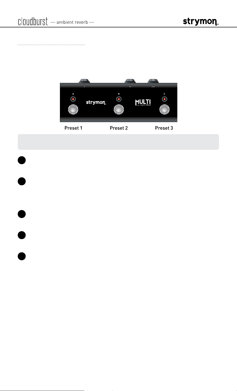
Using MultiSwitch Plus ���������������������������������������������������������������������������������������������� 19
Saving cloudburst Presets with MultiSwitch Plus: �������������������������������������������������� 19
MIDI Functionality ........................................................................................... 20
Configuring cloudburst to Use MIDI �������������������������������������������������������������������������� 20
Saving Presets in MIDI Mode ������������������������������������������������������������������������������������� 25
MIDI Specifications ......................................................................................... 26
MIDI Program Changes ���������������������������������������������������������������������������������������������� 26
MIDI CCs ��������������������������������������������������������������������������������������������������������������������� 27
Factory Reset .................................................................................................. 28
Features .......................................................................................................... 30
Specifications ................................................................................................. 31
Power Adapter Requirements ������������������������������������������������������������������������������������ 31
Appendix 1: Sample Settings ......................................................................... 32
Appendix 2: Power Up Modes Quick Reference ............................................. 34
Strymon Non-Transferable Limited Warranty ............................................... 37
Safety and Compliance Information ............................................................... 38

Knobs and Switches
Front Panel Controls
LED INDICATOR
Lights RED
when the effect is engaged� Use
the FOOTSWITCH to engage and disengage the
effect� Also indicates Power Up Mode features�
(See page 8�)
DECAY
Controls the decay time of the reverberated
signal from 1 second to over 50 seconds� Lower
settings reduce the size of the reverberated
space�
PREDELAY
Sets the amount of time before the reverberated
signal appears, an essential control in creating
an accurate and pleasing reverb� For most
natural results, use lower MIX settings when
using higher PREDELAY
�
FOOTSWITCH
Engages and disengages the effect� The RED LED
on at the top of the pedal indicates that the effect
is engaged�
NOTE: Press and hold the footswitch to configure Expression Pedal parameter
assignments� Please see page 13�
You can optionally configure an external footswitch for FREEZE or INFINITE
mode functions� (See page 16�)
pg 3

Knobs and Switches
Front Panel Controls
ENSEMBLE
Analyzes the input signal and generates a harmonically rich
pad reminiscent of a string section:
off: (left position) no ensemble effect
: (middle position, mezzo piano, meaning “medium soft”)
a medium amount of ensemble for a subtle enhancement
: (right position, “strong” or “loud”) maximum amount
of ensemble effect creating a lush soundscape
MIX
Controls the reverb mix from full dry at
minimum to full wet with no dry signal
at maximum� A 50/50 mix occurs at
approximately 3 o’clock on the knob�
(See page 8
for Dry Signal selection�)
TONE
Adjusts the high-end content of the reverb�
Lower settings create darker, warmer
reverberation� Higher settings are bright and
crisp�
MOD
Adds a wide range of modulation to the
reverberated signal� Modulation is off at the
minimum setting�
pg 4

Rear Panel I/O and Control
I/O MODE SELECTOR
mono : (left position) use with a mono input signal, such as a guitar�
Output is mono� Defaults to True Bypass�
mono stereo : (middle position) use with a mono input signal�
Output is stereo� Bypass mode is Buffered Bypass�
stereo : (right position) use with a stereo input signal� Output is
stereo� Bypass mode is Buffered Bypass�
Stereo I/O requires a TRS adapter or cable� (See the following examples�)
IN
High impedance, ultra
low-noise, discrete Class A JFET
TRS stereo preamp�
OUT
Low impedance TRS stereo
output�
Mono and Stereo I/O Cable Connections
The cloudburst In and Out jacks can accept either TS or TRS type 1/4”
cables for mono or stereo connections, respectively:
NOTE: With a TRS stereo connection, the Tip carries the left signal and the
Ring carries the right signal�
pg 5

Mono In - Mono Out: To connect cloudburst in a mono signal chain, use
TS cables for both cloudburst’s IN and OUT� Set the I/O Selector switch
to mono�
Mono In - Stereo Out: To feed a mono signal into cloudburst, use a TS
cable to cloudburst’s IN� Connect a TRS + dual TS cable to cloudburst’s
OUT to route cloudburst’s stereo signal to a stereo pedal� Set the I/O
Selector switch to mono stereo�
Stereo In - Stereo Out: To connect cloudburst in a stereo signal chain,
use TRS + dual TS cables into both cloudburst’s IN and OUT� Set the I/O
Selector switch to stereo�
*NOTE: Alternatively, you can use a TRS - TRS cable when connecting a pedal
with a TRS stereo input (such as connecting to the TRS stereo input of an El
Capistan tape delay)�
pg 6

Rear Panel I/O and Control (continued)
USBC
Computer connection for MIDI
I/O and firmware updates�
EXP/MIDI
9VDC
Only use an adapter with the
following rating:
• 9VDC, center negative
• 250mA minimum
(Adapter sold separately�)
Multifunction communication jack for external control of cloudburst’s
features and functions� Can be set to operate in one of the following
modes� (See “Configuring the EXP/MIDI Jack” on page 11 for details�)
Expression Pedal Mode (see page 13)�
Favorite Mode (see page 14)�
Freeze Mode (see page 16)�
Infinite Mode (see page 16)�
MIDI Mode (see “Configuring MultiSwitch Plus” on page 18 or
“Saving Presets in MIDI Mode” on page 25)�
pg 7

Power Up Modes
Bypass Mode for Mono I/O
With the rear I/O Mode Selector set to mono, the cloudburst pedal
is set for True Bypass as the default� Setting cloudburst to Buffered
Bypass Mode preserves the high frequency response of your
instrument’s signal through your pedal chain and long cable runs�
NOTE: With the rear I/O Mode Selector set to mono stereo or stereo, the
bypass mode is automatically set to Buffered Bypass�
1 Press and hold the footswitch for at least 2 seconds while powering
up cloudburst� Once the LED flashes, release the footswitch�
2 Toggle the ENSEMBLE (BYPASS MODE) switch to choose between
True or Buffered Bypass Modes� The LED will change color to
indicate the current status as you toggle the switch�
• True Bypass: set the switch to the off (left) position� The LED
lights GREEN (default)�
• Buffered Bypass: set the switch to the (right) position� The
LED lights RED�
3 Press the FOOTSWITCH to store the Bypass Mode and begin using
cloudburst�
NOTE: The Bypass Mode setting persists across power cycles�
pg 8

Power Up Modes
Spillover Mode
Setting cloudburst to Spillover Mode allows the wet reverb signal of the
currently selected preset to “spill” into bypass—or into the next loaded
preset if you’re using a Multiswitch Plus or MIDI for preset switching�
NOTE: Because of the buffer architecture, the current preset must be active
for at least 5 seconds before Spillover between presets will be operational�
Spillover is available immediately when bypassing the effect�
1 Press and hold the footswitch for at least 2 seconds while powering
up cloudburst� Once the LED flashes, release the footswitch�
2 Turn the MOD (SPILLOVER MODE) knob to set Spillover Mode on or
off� The LED will change color to indicate the current status as you
turn the knob�
• Spillover Mode Off: AMBER (default, minimum)
• Spillover Mode On: PURPLE (maximum)
NOTE: When Spillover is set to On, Bypass Mode is set to Buffered Bypass�
3 Press the footswitch to store the Spillover Mode setting and begin
using cloudburst�
NOTE: The Spillover Mode setting persists across power cycles and is not
saved per preset�
pg 9

Power Up Modes
Dry Signal
The Dry Signal can be set in one of three different ways�
• Digital Mode uses the converted dry signal and allows the MIX knob to
dial out the dry signal when turned past the 3 o’clock position�
• Analog Mode keeps the dry signal in analog�
• Kill Dry Mode mutes the analog dry path signal, allowing the MIX
knob to strictly control the “wet” effect output level� This is often
preferable if using cloudburst within an amp’s parallel effects loop
or a mixer’s aux or effects send�
1 Press and hold the footswitch for at least 2 seconds while powering
up cloudburst� Once the LED flashes, release the footswitch�
2 Turn the TONE (DRY SIGNAL) knob to select one of the three Dry
Signal options� The LED will change color to indicate the current
status as you turn the knob�
• Digital Mode: GREEN (default, minimum)
• Analog Mode: RED (12 o’clock)
• Kill Dry Mode: BLUE (maximum)
3 Press the footswitch to store the Dry Signal setting and begin using
cloudburst�
pg 10

Power Up Modes
Configuring the EXP/MIDI Jack
1 Press and hold the footswitch for at least 2 seconds while powering
up cloudburst� Once the LED flashes, release the footswitch�
2 Turn the MIX (EXP/MIDI JACK) knob to select the function of the rear
panel’s EXP/MIDI jack� The LED will change color to indicate the
current status as you turn the knob�
• Expression Pedal Mode: GREEN (default, minimum) - Using a
standard TRS expression pedal, allows continuous control over
any of the knobs� (See page 13 for details�)
• Favorite Mode: AMBER (11 o’clock) - Using a Strymon MiniSwitch,
allows you to recall a Favorite setting� (See page 14 for details�)
• Freeze Mode: RED (12 o’clock) - Using a Strymon MiniSwitch,
allows for infinitely sustained reverberation of the current input
signal without new notes played being added to the reverb� (See
page 16 for details�)
• Infinite Mode: PURPLE (2 o’clock) - Using a Strymon MiniSwitch,
for infinitely sustained reverberation of the current input signal
with new notes played also being added to the reverb� (See page
16 for details�)
(Continued, next page )
pg 11

Configuring the EXP/MIDI Jack (continued)
• MIDI Mode: BLUE - Allows for the selection of three presets using
a Strymon MultiSwitch Plus� Full MIDI functionality is available
by sending MIDI Program Change messages via 1/4” TRS MIDI
connection using a Strymon Conduit or MIDI EXP cable� Up to 300
presets are available via MIDI�
on page 18 or “Saving Presets in MIDI Mode” on page 25�)
(See “Configuring MultiSwitch Plus”
3 Press the footswitch to store the EXP/MIDI Jack Mode and begin
using cloudburst�
NOTE: The EXP/MIDI jack setting persists across power cycles and is not
saved per preset�
pg 12

External Control
RIGHT IN LEFT OUT RIGHT OUT EXP
MIDI IN
USB
MIDI OUT
Expression Pedal Setup
Use a TRS expression pedal to remotely control the knobs of cloudburst�
By default, cloudburst is configured so that an Expression pedal controls
the MIX knob�
1 Configure the EXP/MIDI jack for Expression Mode� (See page 11 for
configuration instructions�)
2 Connect an expression pedal to the EXP/MIDI jack of cloudburst using
a TRS cable�
3 Press and hold the footswitch for at least 2 seconds, until the LED
blinks GREEN�
4 Rock your expression pedal to the HEEL position� The GREEN LED
will stop blinking and remain lit�
5 Set the knob(s) you would like to control to the desired settings for the
HEEL position of the expression pedal�
6 Rock the expression pedal to the TOE position� The LED will turn RED�
7 Set the knob(s) you would like to control to the desired settings for the
TOE position of the expression pedal�
8 Press and release the cloudburst footswitch to exit and store your
expression pedal setup�
NOTE: Your expression pedal assignment is saved per Favorite setting or
MIDI preset�
NOTE: If cloudburst is set to respond to MIDI EXPRESSION and the EXP/MIDI
jack is set to MIDI Mode, you can send MIDI CC# 100 with values 0 (heel) to
127 (toe) to perform the expression pedal setup�
pg 13

External Control
Favorite Switch Setup and Compare Mode
Connect MiniSwitch or other external latching footswitch to store and
recall your Favorite setting�
NOTE: Your Strymon MiniSwitch’s internal jumper switch must be set to the
factory-default FAV/BOOST Mode setting for Favorite Switch functionality�
If you’ve changed the setting of this jumper switch, you’ll need to change it
back to FAV/BOOST Mode—see page 16�
1 Configure the EXP/MIDI jack for Favorite Mode� (See page 11 for
more info�)
2 Connect your MiniSwitch (or, optionally, an external latching switch
with a TRS cable) to the EXP/MIDI jack�
OR
3 Dial in your desired sound�
4 To save your sound as the new Favorite setting, press and hold the
cloudburst footswitch for at least 2 seconds, until the LED blinks
GREEN� Then, press and hold the cloudburst footswitch until the LED
lights BLUE to save the Favorite setting�
Step on the external footswitch to toggle between your current and
Favorite settings on cloudburst�
pg 14

Favorite Switch Setup and Compare Mode (continued)
Compare Mode
With the Favorite or MIDI preset recalled, as a knob or switch is
adjusted, the LED flashes GREEN when the current knob or toggle
switch position matches the setting of the preset�
NOTE: Power Up Mode settings are applied globally and not stored
individually per preset�
NOTE: Saving presets works differently when using MIDI� (See page 20 for
details�)
NOTE: The Favorite setting is stored at MIDI Program Change location 0�
pg 15

External Control
Freeze or Infinite Mode Switch Setup
You can use your Strymon MiniSwitch or an external, non-latching
(momentary) type switch to access the cloudburst Freeze or Infinite
modes�
The Strymon MiniSwitch includes an internal jumper switch that must
be changed from its factory FAV/BOOST Mode setting to work for the
cloudburst Freeze or Infinite momentary switch functionality� Follow
these steps to configure the MiniSwitch’s jumper switch and cloudburst’s
EXP/MIDI
1 Unscrew the four screws on the bottom of the MiniSwitch chassis�
2 Once opened, locate the small jumper underneath the circuit board
and switch it from the center and left pins (FAV/BOOST Mode) to the
center and right pins (TAP Mode
jack for Freeze or Infinite functionality�
)�
Close-up view of the MiniSwitch circuit board jumper switch
TAP
FAV/BOOST Mode
or cloudburst’s Favorite Switch
F
mode—place the jumper on the two
RIGHT pins. (This is how MiniSwitch
is configured from the factory.)
FAV/BOOST
3 Once the jumper conf
TAP Mode
F
Switch modes—place the jumper on
the two LEFT pins.
iguration is complete, secure the cover back on
TAP
FAV/BOOST
or cloudburst’s Freeze or Infinite
your MiniSwitch�
4
Configure cloudburst's EXP/MIDI jack for the Freeze or Infinite mode
as desired� (See page 11 for more info�)
5 Connect your MiniSwitch (or, optionally, a momentary switch with a
TRS cable) to the EXP/MIDI
jack�
pg 16

Freeze or Infinite Mode Switch Setup - continued
OR
6 For Freeze Mode: Play a note or chord, then press and hold the
footswitch to capture and sustain the reverb applied to your signal
indefinitely while holding the external footswitch� As you play new
notes/chords while still holding the external footswitch, you’ll hear
them on top of your “frozen” signal without being added to the reverb�
Release the external footswitch to disengage Freeze mode�
For Infinite Mode:
Press and hold the footswitch to hear reverb
applied indefinitely to all input signals while holding the external
footswitch� Release the external footswitch to disengage Infinite mode�
pg 17

External Control
Configuring MultiSwitch Plus
Configure cloudburst and MultiSwitch Plus for remote access to three
additional presets�
1 Press and hold the cloudburst footswitch while connecting power to
the pedal� Hold for at least 2 seconds, until the LED stops blinking�
2 Turn the DECAY knob all the way counter-clockwise to set the MIDI
CHANNEL to Channel 1� The LED should be GREEN�
3 Turn the PREDELAY knob to select the following MIDI OUT option:
• Send MIDI CC and Other Data: GREEN
• Send Other Data: AMBER
4 Turn the MIX knob all the way clockwise to set the EXP/MIDI jack to
MIDI Mode� The LED should be BLUE�
5 Press the cloudburst footswitch to exit and store the MIDI CHANNEL,
the MIDI OUTPUT setting, and the EXP/MIDI Jack Mode�
6 Connect a TRS cable to cloudburst’s EXP/MIDI jack�
7 Press and hold the A footswitch on MultiSwitch Plus while connecting
the other end of the TRS cable to any one of the three jacks to set it to
Preset Mode�
pg 18
External Control
Using MultiSwitch Plus
Selecting and saving cloudburst presets using MultiSwitch Plus�
NOTE: Footswitches A, B, and C on MultiSwitch Plus correspond to MIDI
Program Changes 1, 2, and 3�
1 Step on a switch that is not illuminated to recall the corresponding
preset�
2 Step on an illuminated switch to bypass cloudburst�
Saving cloudburst Presets with MultiSwitch Plus:
1 Dial in the sound that you would like to save as your preset on
cloudburst�
2 Press and hold the cloudburst footswitch for at least 2 seconds, until
the LED blinks GREEN�
3 Press the A, B, or C MultiSwitch Plus footswitch to save the current
state of the pedal to the desired location�
pg 19

MIDI Functionality
Configuring cloudburst to Use MIDI
Using MIDI unlocks a set of tools that can be used to load any of
cloudburst’s 300 preset locations using a suitable MIDI controller or
interface connected to the cloudburst EXP/MIDI jack� This requires a
Strymon MIDI EXP cable or a MIDI controller/interface, such as Strymon
Conduit, with at least one quarter-inch output�
NOTE: When using a Strymon MIDI EXP Cable, the MIDI OUT Mode must be
set to Off� (See page 24 for details�)
Please see strymon�net/support/cloudburst for a list of compatible
devices�
OR OR
pg 20

Configuring cloudburst to Use MIDI (continued)
STEP 1 SET EXP/MIDI JACK TO MIDI MODE
1 Press and hold the footswitch for at least 2 seconds while powering
up cloudburst� Once the LED flashes, release the footswitch�
2 Turn the MIX (EXP/MIDI JACK) knob clockwise until the LED is BLUE
(maximum) to select MIDI Mode�
NOTE: MIDI data is received on the TIP of the TRS connection of the EXP/
MIDI jack�
pg 21

Configuring cloudburst to Use MIDI (continued)
STEP 2 SET MIDI CHANNEL
3 Turn the DECAY (MIDI CHANNEL) knob to set the MIDI communication
channel� The LED indicates status� Your knob selections are as
follows:
• Channel 1: GREEN (default, minimum)
• Channel 2: AMBER (10 o’clock)
• Channel 3: RED (12 o’clock)
• Channel 4-16: BLUE (maximum) - set by next received MIDI
Program Change message, requires 1⁄4" MIDI connection
Once the LED turns BLUE, it will blink until the pedal receives a
MIDI Program Change message� Once a message is received, the
pedal will be set to the MIDI channel that carried the message and
exits the Power Up Mode to allow you to begin using cloudburst�
(If you’ve successfully configured MIDI Channel 4-16, you can skip
item 4 on the next page�)
pg 22

STEP 2 SET MIDI CHANNEL (CONTINUED)
4 Press the footswitch to exit and store your MIDI Channel setting and
begin using cloudburst�
NOTE: A simple way to check that communication is working is to send CC
#102 with a value of 127 when the footswitch is bypassed� This will enable
the footswitch (and the LED will light RED) if MIDI is properly connected and
configured�
NOTE: If you are only sending data to cloudburst using the Strymon MIDI EXP
cable, the MIDI OUT Mode must be set to OFF� (See page 24 for details on
configuring the MIDI OUT Mode�)
NOTE: MIDI Channel assignment is not saved per Favorite setting or MIDI
preset�
pg 23

Configuring cloudburst to Use MIDI (continued)
STEP 3 SET MIDI OUT MODE
1 Press and hold the footswitch for at least 2 seconds while powering
up cloudburst� Once the LED flashes, release the footswitch�
2 Turn the PREDELAY (MIDI OUT) knob to select what kind of MIDI
data is sent from cloudburst to other MIDI devices� The LED will flash
momentarily to indicate your selection�
• OFF: RED (default, minimum) - No MIDI messages are sent out of
cloudburst�
• THRU: BLUE
(11 o’clock)
- Incoming MIDI messages are sent to
the MIDI Out without any additional MIDI messages generated by
cloudburst�
• SEND CC, OTHER: GREEN
messages generated by
• SEND OTHER: AMBER
by
cloudburst
are sent to the MIDI Out�
(1 o’clock)
cloudburst
(maximum)
- MIDI CC and Sysex
are sent to the MIDI Out�
- Sysex messages generated
3 Press the footswitch to store the MIDI Out Mode and exit�
NOTE: MIDI data is sent from the RING of the TRS connection of the EXP/
MIDI jack�
pg 24

MIDI Functionality (continued)
Saving Presets in MIDI Mode
When in MIDI Mode, the currently loaded settings can be saved to any of
cloudburst’s 300 preset locations at any time�
1 To enter Save Mode, press and hold the footswitch for at least 2
seconds, until the LED blinks GREEN to indicate that cloudburst is
waiting to receive a MIDI Program Change message�
2 To save the current state of the pedal to the currently loaded preset
location, press and hold the footswitch for at least 2 seconds, until the
LED lights BLUE�
OR
To save the current state of the pedal to any preset location, send
the unit a MIDI Program Change on cloudburst’s currently selected
MIDI channel� For example:
• Send MIDI Program Change #10 to save the preset to the
corresponding memory location on the pedal�
• To recall this preset, send MIDI Program Change #10 from your
MIDI controller or sequencer�
pg 25

MIDI Specifications
MIDI Program Changes
Your cloudburst pedal contains 300 preset locations, numbered
sequentially from 0-299� Because MIDI Program Change messages have
a maximum number of 128 (0-127), the presets are grouped into three
MIDI patch banks�
MIDI BANK PRESETS
MIDI BANK 0 = PRESETS 0-127
MIDI BANK 1 = PRESETS 128-255
MIDI BANK 2 = PRESETS 256-299
MIDI PROGRAM CHANGE ACCESSED BY
MIDI PROGRAM
CHANGE 0
MIDI PROGRAM
Favorite setting (accessible via MiniSwitch)
See page 14 for details�
MultiSwitch Plus - footswitch 1
CHANGE 1
MIDI PROGRAM
MultiSwitch Plus - footswitch 2
CHANGE 2
MIDI PROGRAM
MultiSwitch Plus - footswitch 3
CHANGE 3
MIDI PROGRAM
Manual Mode (“knobs”)
CHANGE 127
NOTE: Some MIDI applications and controllers start with MIDI Program
Change 1 instead of 0� In these setups, increment the MIDI Program Change
locations above by one�
The cloudburst pedal always powers up in MIDI Patch Bank 0, so if you
plan to stay within the first 127 presets, simply send a standard MIDI
Program Change message to load a preset�
If you will be using MIDI Banks 1 and/or 2, it is advisable to send a
standard MIDI Bank Change message (MIDI CC# 0 with a value equal to
the MIDI Bank#) before each MIDI Program Change�
Selecting Program Change 127 within any MIDI Bank 0, 1, or 2 will put
cloudburst into Manual Mode� In this mode, cloudburst will be set to the
current knob and switch settings� No preset data can be stored at this
preset location�
pg 26

MIDI Specifications (continued)
MIDI CCs
CC# PARAMETER RANGE ENUMERATION
0 Bank Select 0-2 (0=Bank 1, 1=Bank 2, 3=Bank 3)
11 Ensemble 1-3 (1=off, 2=mp, 3=forte)
12 Decay 0-127
13 Pre-Delay 0-127
14 Tone 0-127
15 Mod 0-127
16 Mix 0-127
27 Footswitch 0, 127 (0=release, 1-127=press)
60 MIDI Expression Off/On 0, 127 (0=off, 1-127=on)
97 Freeze 0, 127 (0=release, 1-127=hold)
98 Infinite 0, 127 (0=release, 1-127=hold)
100 Expression Pedal 0-127 (0=heel, 127=toe)
102 Bypass/Engage 0, 127 (0=bypass, 1-127=engage)
NOTE: All on/off parameters are implemented with 0=off and any other
value (1-127)=on� They are documented as “0” and “127” because many MIDI
controllers send out 0 and 127 for on/off switches�
NOTE: Some MIDI applications and controllers start their MIDI enumeration
with 1 instead of 0� In these setups, increment the numbers above by one�
pg 27

Factory Reset
Performing a Factory Reset restores the pedal to its factory default
Power Up functions, and replaces all stored presets with their factory
default settings�
1 Press and hold the footswitch for at least 2 seconds while powering
up cloudburst� Once the LED flashes, release the footswitch�
2 Press and hold the footswitch again and sweep the PREDELAY
(FACTORY RESET) knob from minimum to maximum and back two
times� The LED will change colors at the extremes of the knob range
and flash RED to indicate when the reset is taking place�
• TURN 1, from minimum to maximum: AMBER
• TURN 2, from maximum to minimum: RED
• TURN 3, from minimum to maximum: AMBER
• TURN 4, from maximum to minimum: The LED flashes RED,
cloudburst resets and restarts
pg 28

Factory Reset (continued)
FACTORY DEFAULT SETTINGS
Bypass Mode: True Bypass
Spillover Mode: Off
Dry Signal: Digital
EXP/MIDI Jack:
MIDI Channel: 1
MIDI OUT Mode: Off
MIDI Expression: On
Assigned to Expression Mode and configured to
control the MIX knob
pg 29

Features
• Hand crafted, computationally intense reverb
• Tone and Pre-Delay controls for flexible reverb tone shaping
• Adjustable modulation for moderate to intensely modulated reverb
sounds
• Analog dry path option for a zero-latency dry signal that is never
converted to digital
• Ensemble effect for lush orchestral-inspired harmonic enhancement
• Dry Kill mode to optionally mute the dry signal, providing control for
the wet signal only
• Stereo input and stereo output (requires “TRS to dual TS” adapter or
cable for each jack)
• True Bypass (electromechanical relay switching)
• Expression pedal input allows the connection of a TRS expression
pedal, MiniSwitch, MultiSwitch Plus, or TRS MIDI connection
• Separate Freeze and Infinite modes for creating continuously
sustaining sounds
• High impedance and ultra-low noise discrete Class A JFET TRS
stereo preamp input
• Full-featured MIDI capability (Continuous Controller, Program
Change, and 300 presets)
• USB-C jack for performing firmware updates and connection to the
Strymon Nixie editor software
• +10dBu maximum input level easily handles instrument and line
level signals
• High performance 520MHz ARM Superscalar processor
• 32-bit floating point processing
• Super low noise, high performance A/D and D/A converters
• Strong and lightweight anodized aluminum chassis
• Designed and built in the USA
pg 30

Specifications
FEATURE VALUE
Input Impedance: 1 Meg Ohm
Output Impedance: 100 Ohm
A/D & D/A: 24-bit 96kHz
Max Input Level +10 dBu
Signal/Noise 116 dB typical
Bypass Switching True Bypass (electromechanical relay switching)
Dimensions 4�5” deep x 1�7” wide x 2�2” tall
Power Adapter Requirements
Use an adapter with the following rating: 9VDC, center negative, 250mA
minimum� (Adapter sold separately�)
pg 31

Appendix 1: Sample Settings
pg 32

Sample Settings
Airstream
MIDI Program Change 0
MiniSwitch Favorite
Pad Thai
MIX
MIX
Beautifier
MIX
MIDI Program Change 1
MultiSwitch Plus A
Thick Slap
MIX
MIDI Program Change 2
MultiSwitch Plus B
MIDI Program Change 3
MultiSwitch Plus C
pg 33

Appendix 2: Power Up Modes
Quick Reference
pg 34

Power Up Modes - Quick Reference
Global parameters and functions can be accessed via a power up
procedure� All power up functions persist through power cycles�
1 Press and hold the footswitch for at least 2 seconds while powering
up cloudburst� Once the LED flashes, release the footswitch�
2 Adjust the desired functions with the controls noted below�
3 Press the footswitch to store your changes and exit Power Up Mode�
POWER UP MODE OPTIONS
BYPASS MODE
FOR MONO I/O
See page 8
for an illustrated
description�
SPILLOVER MODE
See page 9
for an illustrated
description�
DRY SIGNAL
See page 10
for an illustrated
description�
EXP/MIDI JACK
MODE
See page 11
for an illustrated
description�
Set the ENSEMBLE switch - status shown on the LED
• True Bypass: switch in the off (left) position - LED
GREEN (default)
• Buffered Bypass: switch in the (right)
position - LED RED
Turn the MOD knob - status shown momentarily
LED
• Off: AMBER (default, minimum knob position)
• ON: PURPLE (maximum knob position)
Turn the TONE knob - status shown momentarily
LED
• Digital: GREEN (default, minimum knob position)
• Analog: RED (12 o’clock knob position)
• Kill Dry: BLUE (maximum knob position)
Turn MIX knob - status shown on the LED
• Expression: GREEN (default, minimum knob position)*
• Favorite: AMBER (11 o’clock knob position)
• Freeze: RED (12 o’clock knob position)
• Infinite: PURPLE (2 o’clock knob position)
• MIDI: BLUE (maximum knob position)
on the
on the
MIDI CHANNEL
See page 22
for an illustrated
description�
*NOTE: Also see “Expression Pedal Setup” on page 13 to configure your
pedal functionality per preset�
Turn DECAY knob - status shown on the LED
• 1: GREEN (default, minimum knob position)
• 2: AMBER (10 o’clock knob position)
• 3: RED (12 o’clock knob position)
• 4-16: BLUE (maximum knob position) - channel set
by next received MIDI Program Change message
pg 35

Power Up Modes - Quick Reference (continued)
POWER UP MODE OPTIONS
MIDI OUT MODE
See page 24
for an illustrated
description�
FACTORY RESET
See page 28
for an illustrated
description�
Turn PREDELAY knob - status shown momentarily on
the LED
• OFF: RED (default
• THRU: BLUE (11 o’clock knob position)
• ON CC, OTHER: GREEN (1 o’clock knob position)
• ON OTHER: AMBER (maximum knob position)
While holding down the footswitch, turn the PREDELAY
knob from 0% to 100% and back two times - status shown
on the LED
, minimum knob position)
pg 36

Strymon Non-Transferable Limited Warranty
Warranty
Strymon warranties the product to be free from defects in material
and workmanship for a period of two (2) years from the original date
of purchase when bought new from an authorized dealer in the United
States of America or Canada� If the product fails within the warranty
period, Strymon will repair or, at our discretion, replace the product
at no cost to the original purchaser� Please contact your dealer for
information on warranty and service outside of the USA and Canada�
Exclusions
This warranty covers defects in manufacturing discovered while using
this product as recommended by Strymon� This warranty does not
cover loss or theft, nor does the coverage extend to damage caused by
misuse, abuse, unauthorized modification, improper storage, lightning,
or natural disasters�
Limits of Liability
In the case of malfunction, the purchaser’s sole recourse shall be repair
or replacement, as described in the preceding paragraphs� Strymon will
not be held liable to any party for damages that result from the failure
of this product� Damages excluded include, but are not limited to, the
following: lost profits, lost savings, damage to other equipment, and
incidental or consequential damages arising from the use, or inability
to use this product� In no event will Strymon be liable for more than
the amount of the purchase price, not to exceed the current retail price
of the product� Strymon disclaims any other warranties, expressed or
implied� By using the product, the user accepts all terms herein�
How to Obtain Service Under this Warranty
For North American customers: Contact Strymon through our website at
strymon�net/support for Return Authorization and information� Proof of
original ownership may be required in the form of a purchase receipt�
For International Customers: Contact the Strymon dealer from which
the product was purchased from in order to arrange warranty repair
service�
Strymon® is a division of Damage Control Engineering®, LLC�
pg 37

Safety and Compliance Information
This equipment has been tested and found to comply with the limits for a class
B digital device, pursuant to part 15 of the FCC Rules� These limits are designed
to provide reasonable protection against harmful interference in a residential
installation� This equipment generates, uses and can radiate radio frequency
energy and if not installed and used in accordance with the instructions, may cause
harmful interference to radio communications� However, there is no guarantee that
interference will not occur in a particular installation� If this equipment does cause
harmful interference to radio or television reception, which can be determined
by turning the equipment off and on, the user is encouraged to try to correct the
interference by one or more of the following measures:
1) Reorient or relocate the receiving antenna�
2) Increase the separation between the equipment and receiver�
3) Connect the equipment into an outlet on a circuit different from that to which
the receiver is connected�
4) Consult the dealer or an experienced radio/TV technician for help�
© 2023 Damage Control Engineering, LLC�
Strymon, the Strymon logo, and Damage Control Engineering are trademarks or
registered trademarks of Damage Control Engineering, LLC� in the U�S� and/or other
jurisdictions�
REV B
- 01/05/2023
pg 38
 Loading...