

Page 1

IMPORTANT
Keep manual
with warmer
at all times.
Thermaltek 300 “Plus” Portable Warmer
OPERATIONS/MAINTENANCE MANUAL
For Parts or Technical Assistance
1–800–327–0770
Page 2

Table of Contents
Portable Warmer Operation
WARNINGS 2. . . . . . . . . . . . . . . . . . . . . . . . . . . . . . . . . . . . . . . . . . . . . . . . . . . . . . . . . . . . . . . . . . . . . . . . . .
INTRODUCTION 3. . . . . . . . . . . . . . . . . . . . . . . . . . . . . . . . . . . . . . . . . . . . . . . . . . . . . . . . . . . . . . . . . . . . .
SPECIFICATIONS 3. . . . . . . . . . . . . . . . . . . . . . . . . . . . . . . . . . . . . . . . . . . . . . . . . . . . . . . . . . . . . . . . . . . .
WARNING / CAUTION / NOTE DEFINITION 3. . . . . . . . . . . . . . . . . . . . . . . . . . . . . . . . . . . . . . . . . . . . .
CLEANING 3. . . . . . . . . . . . . . . . . . . . . . . . . . . . . . . . . . . . . . . . . . . . . . . . . . . . . . . . . . . . . . . . . . . . . . . . . .
PRE–OPERATION SET–UP 4. . . . . . . . . . . . . . . . . . . . . . . . . . . . . . . . . . . . . . . . . . . . . . . . . . . . . . . . . . .
OPERATING WARMER 5–7. . . . . . . . . . . . . . . . . . . . . . . . . . . . . . . . . . . . . . . . . . . . . . . . . . . . . . . . . . . . . . .
OVERLAY SPECIFICATIONS 8. . . . . . . . . . . . . . . . . . . . . . . . . . . . . . . . . . . . . . . . . . . . . . . . . . . . . . . . . .
PORTABLE WARMER SAFETY FEATURES 9. . . . . . . . . . . . . . . . . . . . . . . . . . . . . . . . . . . . . . . . . . . . .
PORTABLE WARMER SUPPORT POST 10. . . . . . . . . . . . . . . . . . . . . . . . . . . . . . . . . . . . . . . . . . . . . . . .
USING THE I.V. POLE ATTACHMENT SYSTEM 10. . . . . . . . . . . . . . . . . . . . . . . . . . . . . . . . . . . . . . . . .
Troubleshooting Guide 11. . . . . . . . . . . . . . . . . . . . . . . . . . . . . . . . . . . . . . . . . . . . . . . . . . . . . . . . . . . . . . . . . .
Fuse Replacement 11. . . . . . . . . . . . . . . . . . . . . . . . . . . . . . . . . . . . . . . . . . . . . . . . . . . . . . . . . . . . . . . . . . . . . .
Filter Replacement 12. . . . . . . . . . . . . . . . . . . . . . . . . . . . . . . . . . . . . . . . . . . . . . . . . . . . . . . . . . . . . . . . . . . . . .
Assembly Drawings and Parts Lists
BASE ASSEMBLY 13. . . . . . . . . . . . . . . . . . . . . . . . . . . . . . . . . . . . . . . . . . . . . . . . . . . . . . . . . . . . . . . . . . . .
HOSE ASSEMBLY 14. . . . . . . . . . . . . . . . . . . . . . . . . . . . . . . . . . . . . . . . . . . . . . . . . . . . . . . . . . . . . . . . . . . .
SHELL AND HOSE ASSEMBLY 15. . . . . . . . . . . . . . . . . . . . . . . . . . . . . . . . . . . . . . . . . . . . . . . . . . . . . . . .
Page 3

Portable Warmer Operation
WARNING
S Read and understand all information in this manual before using the Thermaltek 300 ”Plus” Portable
Warmer.
S Federal law (U.S.A.) restricts this device to sale by or on the order of a licensed health care professional.
S During warming therapy, the clinician is responsible for monitoring the patient’s condition. It is recom-
mended that the patient’s skin condition, body core temperature, and vital signs be monitored at a mini-
mum of 15 minute intervals. If monitoring does not occur, thermal injury may result, especially if the patient
has the following conditions:
a. Significant peripheral vascular disease (occlusive or diabetic).
b. Low cardiac output.
c. Totally immobilized/anesthetized.
d. Marginal cutaneous perfusion.
Do not use the High temperature setting (110_ F) if the patient has any of the conditions (a, b, c or d) listed
above.
Reduce air temperature or discontinue warming therapy when therapeutic goal is reached, vital sign instability occurs or if the patient’s skin condition is compromised in any way.
This warming system is not intended for use with other external warming devices.
S The Thermaltek ”Plus” Portable Warmer must only be used with a Thermaltek overlay. Use of any
other warming blanket may result in thermal injury.
S The Thermaltek overlay must only be used with the Thermaltek ”Plus” Portable Warmer. Using a Ther-
maltek overlay with any other warming unit may result in thermal injury.
S The temperature settings on the Thermaltek 300 ”Plus”:
High 110_ ± 5_ F (43_ ± 3_ C),
Medium 100_ ± 5_ F (38_ ± 3_ C),
Low 90_ ± 5_ F (32_ ± 3_ C),
are average temperatures at various points around the patient and under the overlay based on a specific
testing protocol. The actual temperature of the air at various points around the patient and under the overlay is determined by different factors including, but not limited to, ambient temperature and use of insulating blankets.
S The Thermaltek 300 ”Plus” Portable Warmer is equipped with an Automatic Temperature Step–Down
(ATS) feature (see page 9 for details) that automatically lowers the temperature from high to medium
after 20 minutes of continuous operation. A brief alarm sounds as the temperature changes. Manual resetting is required to select a new temperature. The ATS feature does not preclude the clinician from monitoring the patient’s skin condition throughout the usage of the warmer. The patient’s skin condition must
always be monitored at a minimum of 15 minute intervals to prevent patient injury.
S Inspect warmer for damage prior to use. If damage is present or warmer has been dropped, do not use
the warmer. Contact your Stryker Service representative.
2
Page 4

Portable Warmer Operation
INTRODUCTION
This manual is designed to assist you with the operation of the Thermaltek 300 ”Plus” Portable Warmer.
Read it thoroughly before using the equipment. The 300 ”Plus” Portable Warmer is for use by qualified medical personnel only.
SPECIFICATIONS
Dimensions: Depth x Width x Height 13” x 13” x 18” (including handle & support
post)
Dimensions (with Base): Depth x Width x Height 22” x 22” x 42”
Weight 10.5 pounds
Weight (with Base and Overlay Bag) 22 pounds
I.V. Pole Attachment System (I.V. Pole Diameter) 5/8” – 1 3/8”
I.V. Pole Socket Support Post (I.V. Pole Socket Diameter) 3/8” – 1/2” (without adaptor)
Electrical Requirements 115 VAC, 60 Hz, 8.0 Amp
NOTE
A ground connection is available on the 300 ”Plus” Portable Warmer. It is located next to the power cord and
is marked with the symbol .
WARNING / CAUTION / NOTE DEFINITION
The words WARNING, CAUTION and NOTE carry special meanings and should be carefully reviewed.
WARNING
The personal safety of the patient or user may be involved. Disregarding this information could result in injury
to the patient or user.
CAUTION
These instructions point out special procedures or precautions that must be followed to avoid damaging the
equipment.
NOTE
This provides special information to make maintenance easier or important instructions clearer.
CLEANING
Be sure warmer is unplugged before cleaning. Hand wash all surfaces of the warmer with a damp cloth and
mild detergent. Dry thoroughly.
The warmer hose material is a non water permeable 200 denier urethane coated nylon. It can be cleaned
by wiping it with a standard hospital cleaning/disinfecting solution.
CAUTION
Do not steam clean or hose off the 300 ” Plus” Portable Warmer. Do not immerse any part of the warmer.
Some of the internal parts of the warmer are electric and may be damaged by exposure to water.
To reduce the risk of shock, DO NOT REMOVE COVER. Refer servicing to qualified service personnel.
3
Page 5
Portable Warmer Operation
PRE–OPERATION SET–UP
WARNING
All electrical medical devices must be tested by qualified personnel for leakage current prior to operation.
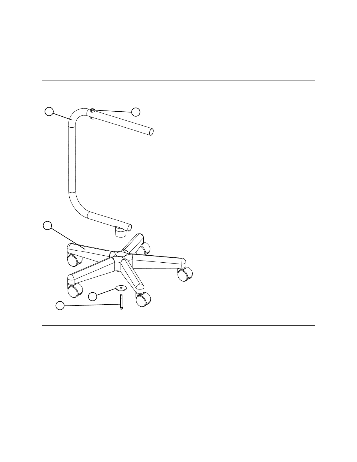
Assembly of the Thermaltek 300 mobile base/stand is required:
A
B
E
1. Using a 3/8” wrench, attach the base tube (A) to
the 5–star base (B) with the bolt (C) and washer (D)
provided.
2. Place the warmer on the base so the support post
rests securely inside of the socket (E) on top of the
base tube.
3. An overlay storage bag is available (not shown) and
provides 3 storage compartments for warmer overlays.
Slip the top loop over the top of the base tube and
secure the bag to the bottom of the base tube with the
velcro strap.
D
C
WARNING
The 300 ”Plus” Portable Warmer is equipped with a hospital grade plug for protection against shock hazard.
It must be plugged directly into a properly grounded three–prong receptacle. Grounding reliability can be
achieved only when a hospital grade receptacle is used. Risk of explosion if used in the presence of flammable anesthetics.
Inspect warmer for damage prior to use. If damage is present or warmer has been dropped, do not use the
warmer. Contact your Stryker Service representative.
DO NOT operate the warmer with the dust cap on or without fully extending the warmer hose.
4
Page 6
OPERATING WARMER
2
6
Portable Warmer Operation
1
3
4
110_ "5_ F
43_"3_ C
100_ "5_ F
38_"3_ C
7
90_" 5_ F
32_" 3_C
3
4
5
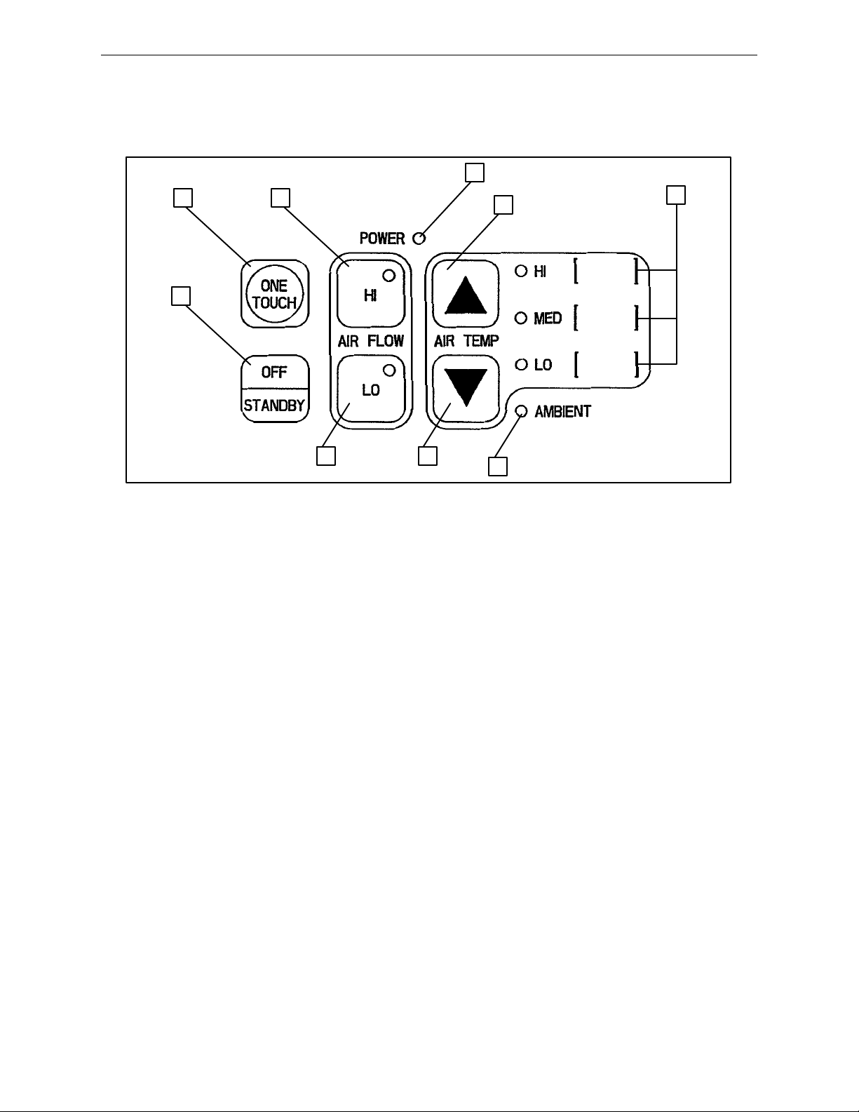
POWER light indicates when the warmer power cord is plugged into the wall socket.
Press the ONE TOUCH key to immediately set the air flow speed on medium and the air temperature
on high. Or...
Press the HI or LO key to select air flow speed. The warmer fan will start when a temperature is selected.
The LED on the key will light to indicate which air flow speed is selected.
Press and release the Y or B key to select an air temperature setting (HI, MED or LO). The correspond-
ing LED will light. The warmer fan will begin operating. The Thermaltek 300 ”Plus” Portable Warmer
is equipped with a ”step–down” feature that automatically lowers the warmer temperature from high to
medium and sounds a brief alarm (3 beeps) after 20 minutes of continuous operation (see page 9).
AMBIENT light indicates room temperature air is being circulated. To circulate ambient air, press and
release the B key until the AMBIENT light comes on.
Press OFF/ST ANDBY to stop warmer operation. The heater and fan will stop and air will stop circulating.
The temperature values indicated on the control panel represent the average temperature of the air at
various points around the patient and under the overlay and are based on specific conditions and test
protocol (see page 9 for details). The values have been rounded to the nearest degree. The actual
temperature of the air around the patient is affected by the room temperature and the use of insulating
blankets.
5
Page 7

Portable Warmer Operation
OPERATING WARMER (CONTINUED)
INDICATIONS
For patient warming
CONTRAINDICATIONS
Do not apply heat to lower extremities during aortic cross–clamping. Thermal injury may occur if heat is applied to ischemic limbs.
1. Place the overlay directly on top of the patient, with the perforated side on the patient’s body.
2. Remove the cap from the hose. DO NOT operate the warmer with the dust cap on or without fully
extending the warmer hose.
3. If the hose is retracted, twist the connector to the left or right to align the four tabs. The hose will
spring out. Continue to pull out the hose until the inside connector is centered and the four tabs are
outside the warmer housing. Twist the hose or the inside connector to lock it in place.
4. To connect the hose to a warming overlay, select an inlet on the overlay. Remove the foam core from
the center of the inlet. Grasp the hose connector around the wide raised ridge. While holding the
inlet tab on the overlay, insert the hose, bottom first. Pull the overlay inlet firmly over the hose connector so the inlet covers at least the first ridge on the connector. (Pulling the inlet over the wide second ridge provides a more secure connection). If an overlay inlet is accidently opened, an adhesive
label is provided in the overlay package to re–seal the opening.
5. To maximize effectiveness, place a cotton blanket over the top of the overlay. Do not place sheets or
blankets between the overlay and the patient.
WARNING
S When using the full–body and lower–body overlays, the urethane hose connector must be positioned so
that the hose as it leaves the blanket is parallel to the center tubes of the overlay.
S When using the upper–body overlay, the urethane hose connector must be positioned so that the hose
as it leaves the blanket is perpendicular to the center tubes of the overlay.
S Position the warmer hose so that the air flow is not restricted.
S The perforated fabric–like side of the overlay must be placed against the patient’s skin to ensure safe
usage. Do not place the polyethylene side of the overlay next to the patient’s skin or thermal injury could
result.
S During warming therapy, the patient’s wounds should be covered. If the patient’s wounds are infected,
the possibility of airborne contamination should be considered.
S Before beginning warming therapy, be sure the patient is dry. If warming therapy is started on a wet pa-
tient, a cooling effect will occur.
S Warming overlays are not sterile and are intended for single patient use only. Placing a sheet between
the warming overlay and the patient does not prevent contamination. Re–use of the warming overlay may
cause cross–contamination.
S Do not sterilize the warming overlays. Materials have not been proven compatible with any sterilization
method. Ethylene Oxide sterilization may leave toxic residue on the warming overlay.
S To prevent suf focation from misuse, do not leave children or infants unattended when administering warm-
ing therapy.
S Avoid direct contact of a laser or an electro–surgical active electrode with overlay material to avoid pos-
sible ignition.
6
Page 8

Portable Warmer Operation
OPERATING WARMER (CONTINUED)
6. Plug warming unit into a properly grounded wall receptacle and ensure the power light comes on.
7. Activate the warmer by pressing the ONE TOUCH key or press an air flow and an air temperature
key to activate the desired settings.
NOTE
If the HI or LO key is pressed prior to the ONE TOUCH key, the warmer will not activate until a temperature
setting is selected.
8. Select the initial temperature setting based on the patient’s condition as per protocol.
Ambient air for mild cooling.
Low 90_ ± 5_ F (32_ ± 3_ C) long term therapy for temperature maintenance.
Medium 100_ ± 5_ F (38_ ± 3_ C) for immobilized/anesthetized patients or those with poor perfusion.
High 110_ ± 5_ F (43_ ± 3_ C) for patients who are moving all extremities and have normal lower
extremity cutaneous perfusion.
WARNING
The following maximum recommended temperatures may be used as a guide, however , the ultimate decision
is the responsibility of the attending physician. The patient’s skin condition, core temperature and vital signs
must be monitored every 15 minutes and the temperature adjusted accordingly.
Patient Condition Maximum Recommended Temperature
Aortic Cross–Clamping Do Not Apply Heat
Significant Vascular Disease (occlusive or diabetic) Medium
Low Cardiac Output Medium
Totally Immobilized/Anesthetized Medium
Marginal Cutaneous Perfusion Medium
WARNING
Monitor the patient’s core, axillary or skin temperature and skin condition at a minimum of 15 minute intervals
during the warming therapy. Reduce air temperature or discontinue therapy when the therapeutic goal is
reached, if vital sign instability occurs, or if the patient’s skin condition is compromised in any way. Notify
physician of vital sign instability immediately. Temperature in excess of the therapeutic goal may result from
failure to monitor the patient’s temperature every 15 minutes. See CONTRAINDICATIONS for patients who
should not receive therapy.
9. Following warming therapy, the hose can be tucked inside the warming unit and secured by twisting
the hose connector until it fits securely in the warmer housing. Seal the hose cap over the retracted
hose to prevent dust from collecting. The hose can also be stored in the extended position by attaching the end of the hose to the hose cap.
10. The hose can be removed from the warmer if it becomes damaged or soiled. Pull the hose out until
the inside connector is visible. Instead of centering the connector as for normal operation, turn it perpendicular to the warmer opening. Squeeze the connector to flatten it, align it with the opening
notches and remove it from the warmer. To reattach the hose perform these steps in reverse.
7
Page 9

Portable Warmer Operation
OVERLAY SPECIFICATIONS
Materials: Polyolefin = Polyethylene + Polypropylene Inlet Rings = Polyethylene Foam
Incinerability: Results in 98% water and 2% ethylene gas (2% ethylene gas is less than the percentage in the
air we breathe)
Full–Body Overlay (92” long x 55” wide)
Upper–Body Overlay (90” long x 30” wide)
Lower–Body Overlay (58” long x 55” wide)
OVERLAY PART NUMBERS
PACU–FB Full Body – Part Number 300–50–00
OR–UB Upper Body – Part Number 300–52–00
OR–LB Lower Body – Part Number 300–54–00
Overlay Storage Bag – 300–68–10
8
Page 10

Portable Warmer Operation
300 ”PLUS” PORTABLE WARMER SAFETY FEATURES
ALARMS
The warmer is equipped with high and low temperature alarms. If alarm sounds, press the OFF/STANDBY
key to silence the alarm.
High Alarm: Whether the temperature setting is on high, medium or low, when the sensor determines that
the internal temperature of the unit is above the desired range for the setting, it automatically shuts the heater
and fan off. The HI LED will flash and an alarm will sound. Press OFF/STANDBY to silence the alarm. Note:
Refer to the troubleshooting guide on page 11 to help determine the cause for the alarm. After correcting
the problem, reset the desired temperature and air flow settings.
Low Alarm: Whether the temperature setting is on high, medium or low, when the sensor determines that
the internal temperature of the unit is below the desired range for the setting, it automatically shuts the heater
and fan off. The LO LED will flash and an alarm will sound. Press OFF/STANDBY to silence the alarm. Note:
Refer to the troubleshooting guide on page 11 to help determine the cause for the alarm. After correcting
the problem, reset the desired temperature and air flow settings.
AUTOMATIC TEMPERATURE STEP–DOWN
The Thermaltek 300 ”Plus” Portable Warmer is equipped with Automatic Temperature Step–Down, a feature
that automatically lowers the warmer temperature from high to medium and sounds a brief alarm (3 beeps)
after 20 minutes of continuous operation. The warmer will remain on the medium setting until another temperature is selected. Any time the high temperature button is pressed, the internal clock will automatically reset
and another 20 minute period will start.
WARNING
The Automatic Temperature Step–Down feature does not preclude the clinician from monitoring the patient’s
skin condition throughout the usage of the warmer. The patient’s skin condition must always be monitored
at a minimum of 15 minute intervals to prevent patient injury.
PORTABLE WARMER TEST PROTOCOL
S Room temperature is between 75_ F and 80_ F.
S A Thermaltek overlay is placed on a standard stretcher mattress and a single cotton blanket is placed
over the overlay.
S The warmer hose is positioned as recommended.
S The warmer is set on high fan speed.
S Temperature readings are taken from thermocouples spaced under the center of the overlay. Average
temperature readings are taken once the temperature under the overlay has stabilized.
9
Page 11

Portable Warmer Operation
300 ”PLUS” PORTABLE WARMER SUPPORT POST
The ”Plus” Portable Warmer support post (item (D)
in the illustration below) is a dual diameter post
with multiple functions:
1. The support post is designed so it only fits into
the socket on the base one way. The warmer
rests securely in the socket on the warmer
base and allows the use of the top handle on
the warmer for moving the warmer around
while it is attached to the base.
2. The support post fits into either foot board socket on Stryker stretchers. Since the ”Plus” Portable Warmer only has one support post, it allows flexibility in placement.
3. The support post allows the warmer to be
placed in any standard 1/2” I.V. pole socket on
a stretcher or bed. Special adaptors that allow
the warmer to rest in larger I.V. sockets (5/8” –
1”) may also be purchased.
USING THE I.V. POLE ATTACHMENT SYSTEM
B
A
C
D
An I.V. pole attachment system is included on all
”Plus” Portable Warmers. It consists of a clamp
mechanism (A) and a vertical support groove (B).
Loosen knob (C), slide the I.V. pole behind the
clamp (A) until it rests in the groove (B) and tighten
knob (C) until the I.V. pole is secure.
The I.V. pole attachment system allows the warmer to be clamped to I.V. poles ranging from 5/8” to
1 3/8” in diameter.
10
Page 12

Troubleshooting Guide
Problem Possible Cause Action
Warmer won’t turn on.
No power LED.
High alarm sounds (HI temperature LED flashes).
Warmer shuts off (no alarm
sounds).
Low alarm sounds (LO temperature LED flashes).
High alarm sounds repeatedly after all obstructions are resolved.
Warmer shuts off (no alarm
sounds) repeatedly.
Low alarm sounds repeatedly. Temperature sensor possibly de-
Main thermostat may have activated.
Power cord not plugged into wall
socket.
Blown fuse.
Hose is obstructed.
Warmer air inlet is blocked.
Filter is dirty.
Hose is obstructed.
Warmer air inlet is blocked.
Overlay disconnected from hose. Reattach overlay. Reset warmer
Temperature sensor possibly defective.
Temperature sensor possibly defective.
fective.
Ensure hose and air inlet are
clear of any obstructions.
Assure power cord is plugged
into the wall socket.
Check fuse and replace, if necessary (see below).
Ensure hose and air inlet are
clear of any obstructions. Reset
warmer temperature and air flow
settings.
Replace filter.
Ensure hose and air inlet are
clear. Allow warmer to cool until
green power LED comes on
(approximately 5 minutes). Reset warmer temperature and air
flow settings.
temperature and air flow settings.
Discontinue use of warmer.
Contact Stryker representative.
Discontinue use of warmer.
Contact Stryker representative.
Discontinue use of Warmer.
Contact Stryker representative.
FUSE REPLACEMENT
The main power fuse (part number 59–57) is located on the outer shell and is
marked by the label at left. When installing a fuse, be sure to replace it as indi–
cated on the label.
NOTE
If a problem occurs with the operation of your 300 ”Plus” Portable Warmer unit within 5 years from the date
of purchase, it can be exchanged for a replacement warmer. The 5 year warranty will continue from the origi-
nal date of purchase. This 5 year warranty does not include the warmer’s filter, base assembly or overlay
storage bag.
11
Page 13

Filter Replacement
C
D
G
A
E
F
B
A
D
Required Tools:
1/8” T–Handle Hex Allen Wrench
Filter Part Number 300–30–37
Replacement Procedure
1. Remove the 3 cap screws (A) holding the inlet cap (B) to the inlet shell (C). The nylon washers and standoffs (D) will come loose when the cap screws are removed. Retain them for reuse.
2. Remove the inner inlet screen (E) and the air filter (F). Place the replacement filter on top of the outer inlet
screen (G) and replace the inner screen (E), standoffs and washers (D) and cap screws (A).
3. Replace the filter every 4–6 months or if the filter appears soiled.
12
Page 14

Base Assembly
Assembly part number
300–1–10
Item Part No. Part Name Qty.
A 300–1–52 Base Tube Weldment 1
B37–199 Tube Closure 1
C37–81 Tube Plug 1
D 300–1–41 Star Base w/Casters 1
E 390–38–5 Support Plate 1
F3–82 Hex Hd. Cap Screw 1
13
Page 15

Hose Assembly
Assembly part number 300–32–10
Item Part No. Part Name Qty.
A 300–32–40 Hose Attachment 1
B 300–32–41 Hose Sleeve Assembly 1
C 300–32–45 Hose End Connector 1
14
Page 16

Shell and Hose Assembly
Assembly part number 300–34
Item Part No. Part Name Qty. Item Part No. Part Name Qty.
A11–52 Flat Washer 2 L 300–90–5 Label, Combo 1
B54–200–917 Packaging 1 M 300–90–6 Label, Caution Clean 1
C37–30 Hole Plug 1 N 921–1–252 Label, Serial No. 1
D 300–30–10 Shell Assembly 1 P 1030–34–38 Cap Strap 1
E (page 14) Hose Assembly 1 R 300–90–8 Label, Caution Hose 1
F 300–32–43 Outlet Cap 1 S 300–90–18 Monitor Patient Tag 1
G 300–90–1 Ops./Maint. Manual 1 T 300–90–19 Label, Monitor Patient 1
H 300–90–2 Label, Serial No./U.L. 1 U 58–14 Cable Tie 1
J 300–90–3 Label, Display 1 W 300–90–20 Label, Step Down 1
K 300–90–4 Display Lexan 1
15
Page 17

6300 Sprinkle Road, Kalamazoo, MI 49001–9799 (800) 327–0770
DH 12/94 300–90–1 REV D
 Loading...