

Stryker SwitchPoint Infinity 3, SwitchPoint Infinity 3-Lite Operation And Maintenance Manual
Page 1

SSwwiittcchhPPooiinntt IInnffiinniittyy®® 33 aanndd SSwwiittcchhPPooiinntt IInnffiinniittyy 33--LLiittee
RRoouutteerr aanndd CCoonnttrrooll SSyysstteemm
OOppeerraattiioonnss aanndd MMaaiinntteennaannccee MMaannuuaall
0678001000
0678003000
Page 2

Page 3

TTaabbllee ooff CCoonntteennttss
11 IInnddiiccaattiioonnss ffoorr UUssee................................................................................................................................................................................................................................77
1.1 Intended Use ................................................................................................................. 7
1.2 Indications ...................................................................................................................... 7
1.3 Contraindications .......................................................................................................... 7
1.4 Wireless Microphone.................................................................................................... 7
22 WWaarrnniinnggss aanndd CCaauuttiioonnss .............................................................................................................................................................................................................. 88
2.1 Warnings ........................................................................................................................ 8
2.2 Cautions ......................................................................................................................... 9
2.3 Notes............................................................................................................................... 9
33 PPrroodduucctt SSyymmbbooll DDeeffiinniittiioonn................................................................................................................................................................................................1100
3.1 EMC Precautions ........................................................................................................11
44 SSyysstteemm OOvveerrvviieeww ................................................................................................................................................................................................................................1133
4.1 An Integrated Voice, Video, and Data Router and Conferencing
Interface ...............................................................................................................13
55 EEqquuiippmmeenntt CCoonnnneeccttiioonnss........................................................................................................................................................................................................1144
5.1 Connectors Used by the SwitchPoint Infinity 3 Control System...........................14
5.2 Connections Overview ............................................................................................... 14
5.2.1 Video Inputs ....................................................................................................14
5.2.2 Video Outputs .................................................................................................14
5.2.3 Audio Inputs ....................................................................................................15
5.2.4 Audio Outputs .................................................................................................15
5.2.5 RS-232 Connectivity ......................................................................................15
5.2.6 KVM..................................................................................................................15
5.2.7 Video Network Hub™ .................................................................................... 15
5.2.8 SuiteLink
5.2.9 Sidne
5.2.10 Local Codec ..................................................................................................16
5.2.11 Campus Codec .............................................................................................16
66 TToouucchh PPaanneell IInntteerrffaaccee................................................................................................................................................................................................................1177
6.1 Control Section............................................................................................................ 18
6.2 Quick Button Bar .........................................................................................................18
6.3 Global Taskbar ............................................................................................................19
6.3.1 Volume Control............................................................................................... 19
6.3.2 Setup................................................................................................................19
6.3.3 Save Preset..................................................................................................... 20
®
and SuiteView®...........................................................................15
®
Voice Activation System or SDC3 Voice Package ...................... 16
1
Page 4

6.3.4 SORN Support................................................................................................20
6.3.5 Help .................................................................................................................. 21
6.3.6 Suite Power..................................................................................................... 22
6.3.7 Private..............................................................................................................22
6.4 Home and Presets Buttons........................................................................................23
6.4.1 Home Button ................................................................................................... 23
6.4.2 Presets Button ................................................................................................23
6.5 Screensaver................................................................................................................. 23
77 RRoouuttiinngg VViiddeeoo..............................................................................................................................................................................................................................................2244
7.1 Simple Routing ............................................................................................................24
7.1.1 Viewing a Source on a Display.....................................................................25
7.1.2 Viewing and Recording a Source on a Display.......................................... 26
7.1.3 Using Sidne or SDC3 along with Viewing and Recording a Source
on a Display ................................................................................................. 27
7.2 Visual Routing .............................................................................................................28
7.2.1 Creating a Visual Route ................................................................................ 29
7.2.2 Unrouting a Selection ....................................................................................29
7.2.3 Saving a Visual Route as a Preset ..............................................................29
7.3 Text Routing ................................................................................................................ 29
7.3.1 Creating a Text Route ................................................................................... 29
7.3.2 Creating a New Text Route .......................................................................... 30
7.3.3 Saving a Text Route as a Preset .................................................................30
88 PPIIPP aanndd QQuuaadd VViieeww GGeenneerraattoorr FFuunnccttiioonnaalliittyy ............................................................................................................................3311
8.1 PIP................................................................................................................................. 31
8.1.1 Selecting Images............................................................................................ 31
8.1.2 Screen Layout.................................................................................................31
8.1.3 Swap Images .................................................................................................. 32
8.1.4 PIP Small / PIP Large.................................................................................... 32
8.2 Quad View....................................................................................................................32
8.2.1 Selecting Images............................................................................................ 33
8.2.2 Screen Layout.................................................................................................33
8.2.3 Select Destinations ........................................................................................33
99 PPrreesseettss......................................................................................................................................................................................................................................................................3344
9.1 Recalling Presets ........................................................................................................34
9.2 Saving a Preset ........................................................................................................... 34
9.3 Previewing Presets ..................................................................................................... 36
9.4 Unrouting Presets ....................................................................................................... 36
1100 CCaallllss............................................................................................................................................................................................................................................................................3377
10.1 Manual Dial Tab ........................................................................................................ 38
2
Page 5

10.2 Campus Status .......................................................................................................... 39
10.3 Campus Codec Call .................................................................................................. 39
10.4 Room-to-Room Call .................................................................................................. 40
10.5 Active Call .................................................................................................................. 42
10.5.1 Active Call Status ......................................................................................... 43
10.6 Private.........................................................................................................................44
10.7 Last 10 Dialed ............................................................................................................ 44
10.8 Call Groups ................................................................................................................45
10.9 Storing a Speed Dial Call Setting ........................................................................... 46
10.10 Offsite (Codec) Calls...............................................................................................47
10.11 Making a Codec IP Call .......................................................................................... 47
10.11.1 Making a Codec ISDN Call .......................................................................47
10.11.2 Making a Codec Gateway Call .................................................................48
10.11.3 Waiting for an Offsite Call..........................................................................48
10.12 Managing SuiteView Functionality ....................................................................... 49
10.12.1 Desktop User Access................................................................................. 49
10.12.2 Managing Call Settings.............................................................................. 49
10.13 Advanced Call Types..............................................................................................50
10.13.1 Broadcast..................................................................................................... 50
10.13.2 View Only..................................................................................................... 51
10.13.3 Meeting Room.............................................................................................51
1111 SSuurrggiiccaall TTiimmeeoouutt..............................................................................................................................................................................................................................5533
11.1 Surgical Timeout Procedure .................................................................................... 53
1122 CCoonnttrrooll PPaanneell ..........................................................................................................................................................................................................................................5577
1133 PPCC DDeevviiccee CCoonnttrrooll ........................................................................................................................................................................................................................5588
1144 AAuuddiioo CCoonnttrroollss ......................................................................................................................................................................................................................................5599
14.1 Speaker Controls ......................................................................................................59
14.2 Input Levels................................................................................................................ 59
14.3 Output Levels.............................................................................................................60
1155 DDiissppllaayy ..................................................................................................................................................................................................................................................................6622
1166 RRoooomm CCaammeerraa ........................................................................................................................................................................................................................................6633
16.1 Advanced ................................................................................................................... 64
1177 RReemmoottee DDeevviiccee CCoonnttrrooll ......................................................................................................................................................................................................6655
17.1 Stryker Digital Capture (SDC).................................................................................65
1188 OObbsseerrvvaattiioonn RRoooomm........................................................................................................................................................................................................................6666
18.1 Routing Video ............................................................................................................ 67
3
Page 6

18.2 Adjusting the Speaker Volume................................................................................67
18.3 Adjusting the Pan/Tilt/Zoom ....................................................................................67
18.4 Advanced ................................................................................................................... 67
1199 RRoooomm LLiigghhttss................................................................................................................................................................................................................................................6688
2200 CCaalliibbrraattiinngg tthhee TToouucchh PPaanneell......................................................................................................................................................................................6699
2211 SSeettttiinngg tthhee DDaattee aanndd TTiimmee ............................................................................................................................................................................................7711
2222 SSOORRNN SSuuppppoorrtt ......................................................................................................................................................................................................................................7722
2233 SShhuuttttiinngg DDoowwnn tthhee SSwwiittcchhPPooiinntt IInnffiinniittyy 33........................................................................................................................................7744
2244 EEmmeerrggeennccyy OOppeerraattiioonn............................................................................................................................................................................................................7755
2255 TTrroouubblleesshhoooottiinngg GGuuiiddee........................................................................................................................................................................................................7766
25.1 Useful Tips .................................................................................................................76
25.1.1 Use Presets................................................................................................... 76
25.1.2 Use Fresh Batteries .....................................................................................76
25.1.3 Pretest Offsite Connections ........................................................................ 76
25.1.4 Practice In Advance ..................................................................................... 76
25.1.5 Video Routing Tips .......................................................................................76
25.2 Troubleshooting the SwitchPoint Infinity 3 ............................................................ 78
25.2.1 Router Drawings...........................................................................................78
25.2.2 Troubleshooting Steps ................................................................................81
25.2.3 Connecting External Video Devices..........................................................86
2266 PPhhyyssiiccaall aanndd EElleeccttrriiccaall SSppeecciiffiiccaattiioonnss ................................................................................................................................................8888
26.1 SPI3 Environmental Specifications ........................................................................ 88
26.2 SPI3 Electrical and Physical Specifications..........................................................88
26.3 SPI3-Lite Environmental Specifications ................................................................89
26.4 SPI3-Lite Electrical and Physical Specifications .................................................. 89
26.5 SPI3 Control System Electrical and Physical Specifications.............................. 90
26.6 All-In-One Control System Electrical and Physical Specifications .................... 90
26.7 Required Equipment.................................................................................................90
26.8 Separation Distances ...............................................................................................94
2277 MMaaiinntteennaannccee..............................................................................................................................................................................................................................................9966
27.1 Periodic Maintenance Schedule .............................................................................96
27.2 Preventative Maintenance Restart ......................................................................... 98
27.3 Cleaning Instructions ................................................................................................ 98
27.4 Disposition of the Product........................................................................................98
27.5 Removability of Batteries .........................................................................................98
27.5.1 Replacing the Wireless Microphone Batteries .........................................99
4
Page 7

27.6 Damage Claims and Service...................................................................................99
27.6.1 Damage Claims ............................................................................................ 99
27.6.2 Service .........................................................................................................100
2288 EEUULLAA TTeerrmmss ........................................................................................................................................................................................................................................ 110011
2299 WWEEEEEE PPaassssppoorrtt,, SSPPII33--LLiittee.................................................................................................................................................................................... 110033
3300 CCoonnttaacctt IInnffoorrmmaattiioonn.............................................................................................................................................................................................................. 112200
5
Page 8

Page 9

1
Indications for Use
1.1 Intended Use
Stryker SwitchPoint Infinity®3 (SPI3) Control System is intended to be a central point of
control and integration of ancillary compatible equipment, audio, video, and data routing,
as well as teleconferencing for medical personnel.
1.2 Indications
General surgical population.
1.3 Contraindications
None.
1.4 Wireless Microphone
The wireless microphone is available and serves as another audio input to the
SwitchPoint Infinity 3 Control System audio subsystem. The microphone uses Ultra High
Frequency (UHF) to transmit to the receiver. UHF is a common frequency range which
television stations use to broadcast their signal. The wireless microphone has been
tested to meet medical EMC and safety standards. The Instructions for Use contains
language informing the users of these radio frequencies. The theoretical maximum range
of the microphone transmitter is 91.5m (300’). This range is greatly limited inside of a
hospital operating room, due to the general construction of hospitals. The users are
instructed to test all equipment with the wireless microphone system to ensure that no
interference exists prior to the use of Stryker SwitchPoint Infinity 3 Control System.
7
Page 10

2
Warnings and Cautions
In this manual, the terms and definitions below apply.
• WWaarrnniinngg:: Possible injury to the patient or user.
• CCaauuttiioonn:: Possible damage to the equipment.
• NNoottee:: More information to clarify the instructions.
2.1 Warnings
To prevent possible injury to the user and the patient, the user must follow these
requirements:
1. Read this manual fully before you use this equipment.
2. Before you use this equipment you must be trained medical personnel, with complete
knowledge on how to use this equipment.
3. Do a test of this equipment before surgical procedures. This equipment was fully
tested at the factory before it was shipped.
4. To prevent electrocution, do not remove product covers.
5. Do not repair or adjust the equipment, unless you are instructed to do so in this
manual.
6. Use of controls or adjustments or performance of procedures other than those
specified herein may result in hazardous radiation exposure.
7. To prevent a fire, keep instruments away from flammable materials (such as gauze
or surgical drapes).
8. To prevent a fire, allow adequate air circulation to prevent internal heat buildup.
9. Do not touch the front panel input or output circuitry and a patient at the same time,
as there is a risk of electrical shock.
10. The electrical installation of the operating room must be in compliance with the
applicable IEC, CEC, and NEC requirements.
11. To avoid risk of electric shock, this equipment must only be connected to a supply
mains with protective earth.
12. Disconnect the unit from the electrical outlet before you examine the system
components.
13. The wireless microphone functionality included in this device contains a radio
transmitter and receiver. Hospitals and health care facilities may be using equipment
that is sensitive to radio frequencies (RF).
Prior to using this device in a surgical procedure, perform the following steps to
ensure electromagnetic compatibility among operating room devices:
a. Identify any medical devices located within the SwitchPoint Infinity 3 Control
System’s communication range (Theoretical maximum of 91.5m [300’]).
b. Test each device for compatibility with the SwitchPoint Infinity 3 Control System:
Power on the medical devices.
8
Page 11

Perform a variety of functions with the SwitchPoint Infinity 3 Control System,
such as speaking through the microphone and powering on and off the
microphones.
c. Reposition devices as necessary to maintain electromagnetic compatibility, or
disable the wireless microphone.
This device complies with Part 15 of the FCC Rules. Operation is subject to the
conditions that this device does not cause harmful interference.
2.2 Cautions
1. Carefully unpack this device and check for damage. Refer to the standard warranty if
the device is damaged.
2. To prevent damage, follow all sterilization and disinfection instructions in this manual.
A deviation may cause damage. DO NOT STERILIZE OR DISINFECT THE
CONTROL UNIT OR THE TOUCH PANEL DISPLAY.
3. Only Stryker approved personnel can adjust, modify, and repair this equipment.
4. Do not install the unit in a location near heat sources such as radiators or air ducts, or
in a place subject to direct sunlight, excessive dust, mechanical vibration, or shock.
5. The leakage current could increase when connected to other equipment.
6. Do not position the unit such that it is difficult to disconnect the power cord.
7. Caution: Federal law (United States of America) restricts this device to use by, or on
order of, a physician.
2.3 Notes
1. Stryker Communications has verified that the SwitchPoint Infinity 3 Control System
complies with the electromagnetic compatibility requirements for medical devices as
specified in IEC 60601-1-2. RF communication equipment such as the wireless
microphone in the SwitchPoint Infinity 3 Control System, however, can still affect
other medical electrical equipment in the operating room.
2. The screen captures in this manual may differ slightly from each individual
SwitchPoint Infinity 3 setup, depending on configuration.
3. The terms “SwitchPoint Infinity” and “SPI” are used interchangeably throughout the
manual.
4. Operate the unit on 100 VAC 50/60 Hz in Japan, 120 VAC 50/60 Hz in North
America, and 100-240 VAC 50/60 Hz in other locations.
5. The nameplate indicating operating voltage, power consumption, and other
information is located next to the power entry module on the front of the SPI3 and on
the back of the SPI3-Lite.
6. This equipment uses only RoHS approved/complaint lead-free solder.
9
Page 12
3
Product Symbol Definition
The following symbols may be found on the SwitchPoint Infinity equipment:
Follow instructions for use.
The book symbol is intended to refer the user to important safety
operating and maintenance (service) instructions in the literature
accompanying the product.
An exclamation mark within a triangle is intended to alert the user to the
presence of important operating and maintenance (service) instructions
in the literature accompanying the product.
A lightning bolt indicates the presence of hazardous voltage. Refer all
service to authorized personnel.
Temperature limits
Denotes humidity limits.
Denotes pressure limits.
Denotes compliance to European Community Directive 93/42/EEC.
Denotes compliance to CSA Standard C22.2, 60601-1 - M90, AS 3200,
IEC 60601-1, UL 60601-1, EN 60601-1
Denotes the date the equipment was manufactured.
Denotes the manufacturer of the device.
Denotes product/part number.
Denotes product/serial number.
Denotes lot or batch number.
Denotes European Representative.
10
Page 13
For U.S. audience only - Caution: Federal Law (USA) restricts this
device to sale by or on the order of a physician.
Denotes quantity.
Accessories
Repair Kit
Video Router
Denotes Class 1
Class 1 Equipment: equipment in which the protection against electric
shock does not rely on Basic Insulation only, but includes an additional
safety precaution in such a way that means are provided for the
connection of Accessible Conductive Parts to Protective (ground)
Conductor in the fixed wiring of the installation in such a way that
Accessible Conductive Parts cannot become Live in the event of a
failure of the Basic Insulation.
In accordance with European Community Directive 2002/96/EC on
Waste Electrical and Electronic Equipment, this symbol indicates that
the product must not be disposed of as unsorted municipal waste but
should be collected separately.
Note: The device does not contain any hazardous materials.
Legal regulations may include specifications regarding the disposal of
this product. We request that you contact Stryker when you plan to
withdraw this device from service for discard.
Denotes the device contains more than .002% cadmium.
Denotes the device contains more than .0005% mercury.
Denotes the device contains more than .004% lead.
3.1 EMC Precautions
This device is considered medical electrical equipment and requires special precautions
regarding EMC and needs to be installed and put into service according to the
information provided.
Portable and mobile RF communications equipment can affect this device’s performance
and must be used in accordance with the following information.
11
Page 14

WWaarrnniinngg::
• The use of accessories, transducers, or cables other than those specified, with the
exception of those sold by Stryker, may result in increased electromagnetic
emissions or decreased immunity of the equipment or system.
• The equipment should not be used adjacent to or stacked with other equipment. If
stacking or adjacent placement is necessary, the equipment should be observed to
verify normal operation in the configuration in which it will be used.
12
Page 15

4
System Overview
This manual describes the user interface and functionality for the SwitchPoint Infinity 3
Control System and Router (SPI3) and the SwitchPoint Infinity 3-Lite Control System and
Router (SPI3-Lite). Throughout this manual, unless otherwise specified, “SwitchPoint
Infinity refers to both SPI3 and SPI3-Lite.
SwitchPoint Infinity 3 was designed to work with Stryker devices as well as other devices.
Contact Stryker to determine if a device is compatible with SwitchPoint Infinity 3.
4.1 An Integrated Voice, Video, and Data Router and
Conferencing Interface
The SwitchPoint Infinity 3 Control System is built with high quality video and audio
components. It is designed to operate and communicate with a broad range of equipment
such as cameras, monitors, and surgical equipment, including the insufflator and light
source.
The Touch Panel Interface provides a convenient, easy method to control every function
of the SwitchPoint Infinity 3 Control System.
13
Page 16

5
Equipment Connections
5.1 Connectors Used by the SwitchPoint Infinity 3 Control
System
The SwitchPoint Infinity 3 Control System uses various commercial-grade video and
audio cables to interconnect equipment.
The primary types of cables are used in wiring video systems: Composite cables, which
have a BNC connector; RGB-HV cables, which have an HD-15 connector; S-Video
cables, which have a 4-pin mini-DIN connector; and DVI cables. BNC connectors are
push and turn type connectors; HD-15 connectors are push and screw type connectors;
and DIN connectors are push only type connectors. On some monitors, S-Video inputs
may be labeled Y/C or S-VHS, and RGB-HV inputs may be labeled PC, Computer, or
VGA.
The room speaker connection on the SwitchPoint Infinity 3 Control System uses a
Phoenix connector.
5.2 Connections Overview
5.2.1 Video Inputs
The number of video inputs is dependent upon each SwitchPoint Infinity Router. Source
inputs are available to receive video directly from Endoscopic and Room Cameras,
Printer, Digital Capture Device, Voice Control Device, and other video device outputs. All
of the connections are located on the front panel. For video input wiring, connect each
device output to an available video input on the SwitchPoint Infinity 3 Control System
connection panel.
5.2.2 Video Outputs
WWaarrnniinngg:: Do not touch the internal pin of the BNC video out jacks and the patient
simultaneously. Doing so may cause the patient to receive an electric shock.
The number of outputs is dependent upon each SwitchPoint Infinity Router. Outputs are
available to send video directly to flat panel displays, monitors, projectors, and other
video device inputs. All of the connections are located on the front panel. For video
output wiring, connect each device input to an available video output on the SwitchPoint
Infinity 3 Control System connection panel. When connected to a “loop-thru” video
device, the SwitchPoint Infinity 3 Control System will route the source to the device input
and receive the output signal from the device for further routing to a monitor (if selected).
14
Page 17

5.2.3 Audio Inputs
There are 10 audio inputs available on the front panel of the SwitchPoint Infinity 3 Router:
• Two mic level inputs
• Eight line level inputs
There are four audio inputs available on the front panel of the SwitchPoint Infinity 3-Lite
Router:
• One mic level input
• Three line level inputs
Any audio input may be used for connecting audio devices, as there are no reserved
audio inputs for specific devices. For example, the wireless microphone receiver can be
connected to any of the microphone inputs, as can the Sidne. Phantom power is
available for mic inputs. Make sure that phantom power is not enabled for microphones
that do not require it.
5.2.4 Audio Outputs
There are eight line level outputs and two speaker outputs available on the front panel of
the SwitchPoint Infinity 3 Router. Two of the line level outputs are designated for
connection to an external amplifier (applies only to SPI3). There are two line level outputs
and two speaker outputs available on the front panel of the SwitchPoint Infinity 3-Lite
Router. The Video Network Hub™ and room speakers are some of the devices that are
connected to the audio outputs on the SwitchPoint Infinity 3 Control System.
5.2.5 RS-232 Connectivity
The SwitchPoint Infinity 3 Router has 16 RS-232 ports that can be used to connect
devices that use serial communications, such as PTZ Cameras and Flat Panel monitors.
SPI3-Lite can be configured with either four or eight RS-232 ports.
5.2.6 KVM
There are three USB connections available for PC KVM control allowing for keyboard
and mouse emulation on up to three PCs.
5.2.7 Video Network Hub™
This device will facilitate room-to-room connectivity for video conferencing. If your system
is equipped with a Hub Codec, the Codec will be housed in the Video Network Hub and
will allow offsite connectivity. The Video Network Hub is connected to the SwitchPoint
Infinity 3 Control System using the Audio In and Out connectors, the Ethernet
connection, and the video input and output connectors. Details of the connection and
operation of the Video Network Hub are contained in the Operations and Maintenance
manual for that equipment.
5.2.8 SuiteLink®and SuiteView
SuiteLink is an IP-based Video Hub that coordinates Stryker endpoints with Campus
Codec functionality through an Ethernet connection. It also supports the broadcast of
video from these endpoints to IP-based desktop users in conjunction with the SuiteView
®
15
Page 18

product. Users can view available video sources from these endpoints, and with proper
setup and permissions, they have the ability to change video sources and manipulate the
camera views from their desktop computer.
Only one SuiteLink or Video Network Hub can be configured per facility. SuiteLink
supports up to two hub Codecs for video conferencing calls.
5.2.9 Sidne®Voice Activation System or SDC3 Voice Package
The SwitchPoint Infinity 3 Control System can be configured to communicate with the
Sidne Voice Activation System or SDC3 Voice Package with an optional upgrade to the
Sidne or SDC3 system. The SwitchPoint Infinity 3 Control System and Sidne are
connected via Ethernet through an Ethernet switch.
5.2.10 Local Codec
A local Codec supports a dedicated video conferencing Codec for one endpoint only.
NNoottee::
•• TThhee aaccttuuaall ccaabbllee ccoonnnneeccttiioonnss ttoo tthhee SSwwiittcchhPPooiinntt IInnffiinniittyy 33 CCoonnttrrooll SSyysstteemm
mmuusstt bbee ssyynncchhrroonniizzeedd wwiitthh tthhee ssooffttwwaarree.. TThhiiss ccoonnffiigguurraattiioonn iiss mmaaiinnttaaiinneedd iinn
tthhee AAddvvaanncceedd SSeettuupp aarreeaa ooff tthhee uusseerr iinntteerrffaaccee.. CChhaannggiinngg ccaabbllee ccoonnnneeccttiioonnss
wwiitthhoouutt cchhaannggiinngg tthhee ssooffttwwaarree ccoonnffiigguurraattiioonn wwiillll rreessuulltt iinn ssyysstteemm
mmaallffuunnccttiioonn.. CCoonnttaacctt tteecchhnniiccaall ssuuppppoorrtt ffoorr aassssiissttaannccee..
•• SSPPII33 aanndd SSPPII33--LLiittee ccaannnnoott bbee ccoonnnneecctteedd ttoo aa LLooccaall CCooddeecc aanndd aa CCaammppuuss
CCooddeecc aatt tthhee ssaammee ttiimmee..
5.2.11 Campus Codec
The Campus Codec feature applies only to facilities with SuiteLink for IP
Videoconferencing.
Stryker endpoints can be configured with a Campus Codec to enable IP
videoconferencing to other Stryker endpoints with Campus Codec functionality and to
enable IP broadcasting of video from that endpoint. A Campus Codec works with
SuiteLink and supports campus status, remote video source control, and remote PTZ
control.
NNoottee:: SSPPII33 aanndd SSPPII33--LLiittee ccaannnnoott bbee ccoonnnneecctteedd ttoo aa LLooccaall CCooddeecc aanndd aa CCaammppuuss
CCooddeecc aatt tthhee ssaammee ttiimmee..
16
Page 19

6
Touch Panel Interface
WWaarrnniinngg:: The SwitchPoint Infinity 3 Control System interface can be displayed on
up to two Touch Panels. The Touch Panels are not sterile devices.
NNoottee::
•• MMoosstt ssttyylluusseess ccaannnnoott bbee uusseedd oonn tthhee SSwwiittcchhPPooiinntt IInnffiinniittyy 33 CCoonnttrrooll SSyysstteemm’’ss
TToouucchh PPaanneell iinntteerrffaaccee.. FFoorr bbeesstt rreessuullttss,, uussee yyoouurr ffiinnggeerr oorr aa gglloovveedd hhaanndd oonn
tthhee TToouucchh PPaanneell iinntteerrffaaccee..
•• TToo eexxiitt oouutt ooff aannyy ssccrreeeenn ootthheerr tthhaann tthhee HHoommee ssccrreeeenn,, pprreessss tthhee rreedd XX iinn tthhee
ttoopp rriigghhtt ccoorrnneerr ooff tthhee rreessppeeccttiivvee ppaaggee,, oorr pprreessss tthhee HHoommee bbuuttttoonn..
•• AAvvooiidd ggeettttiinngg mmooiissttuurree oonn tthhee ssuurrffaaccee ooff tthhee ssccrreeeenn,, aanndd bbee ccaarreeffuull nnoott ttoo
ssccrraattcchh tthhee ssuurrffaaccee wwiitthh iinnssttrruummeennttss oorr ffiinnggeerr nnaaiillss..
•• FFoorr iinnffoorrmmaattiioonn oonn cchhaannggiinngg tthhee iinnssttiittuuttiioonn aanndd rroooomm nnaammeess,, aass wweellll aass
cchhaannggiinngg tthhee ssyysstteemm llaanngguuaaggee,, rreeffeerr ttoo tthhee IInnssttaallllaattiioonn MMaannuuaall..
The Touch Panel Interface controls every function of the SwitchPoint Infinity 3 Control
System. It offers a menu of options dependent on the equipment that is installed in that
particular room. To use the Touch Panel, touch the displayed “button” with the soft
surface of your finger. When a button is selected in the program, it will turn orange.
Depending on the function it may stay orange, or return to blue after a few seconds.
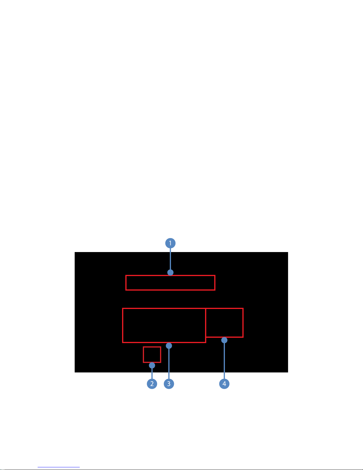
The SwitchPoint Infinity 3 Control System Touch Panel interface is composed of four
sections: the Control Section (Item 3), the Quick Button Bar (Item 4), the Global Taskbar
(Item 5), and the Menu Buttons (Item 2).
17
Page 20
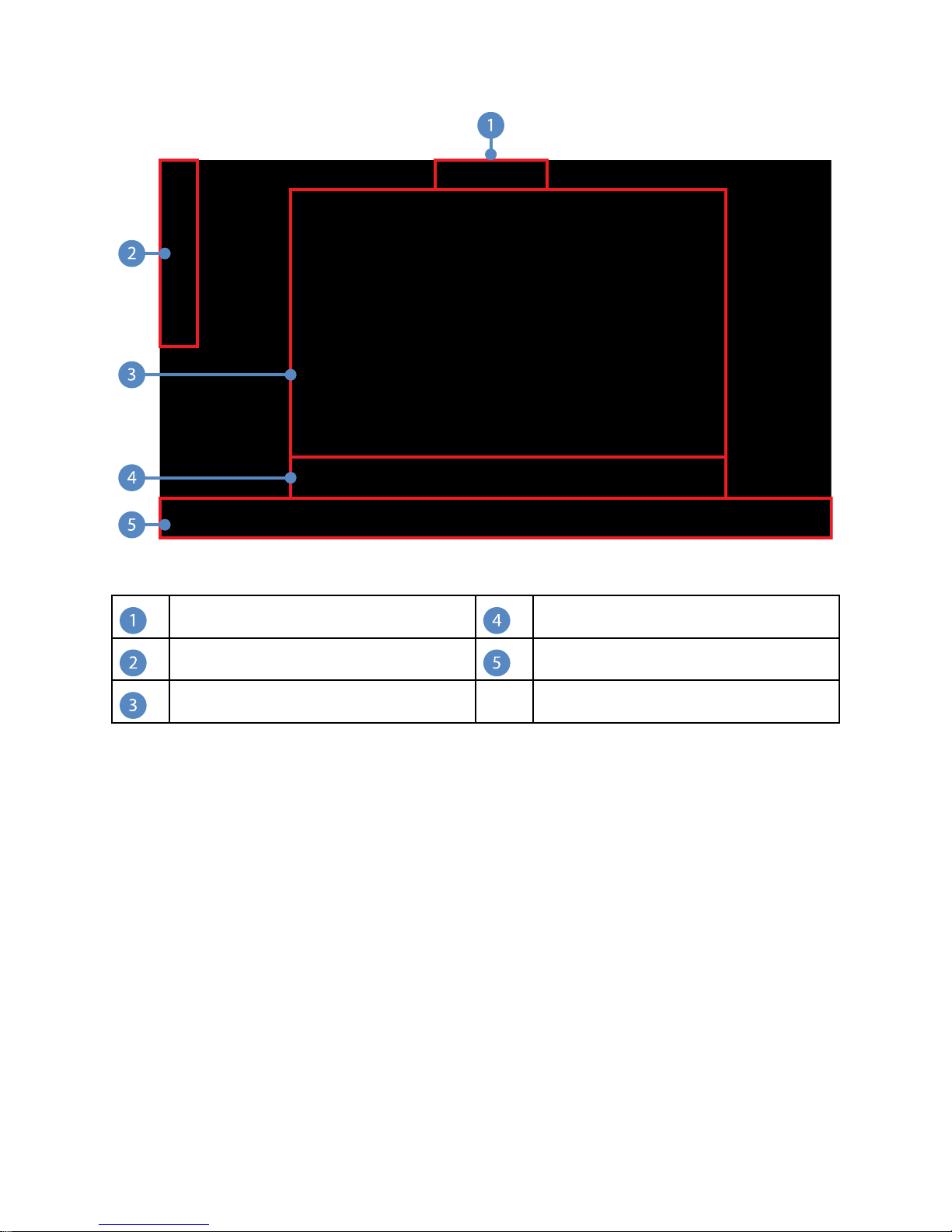
FFiigguurree 11.. HHoommee PPaaggee
Title Bar
Menu Buttons
Control Section
Quick Button Bar
Global Taskbar
6.1 Control Section
The Control Section is the main area of the screen. From here, the user can navigate the
system. By default, the Simple Routing screen is displayed as the Home Page in the
Control Section.
6.2 Quick Button Bar
The Quick Button Bar is displayed below the Control Section. It provides quick access to
the functions most often used, such as the Calls, Advanced Routing, Picture-in-Picture
view, QUAD view, Audio, Display, Room Cam, and Surgical Timeout screens. Pressing a
button in the Quick Button Bar opens the respective display in the Main Area.
NNoottee:: QQUUAADD vviieeww iiss nnoott aavvaaiillaabbllee ffoorr SSPPII33--LLiittee
18
Page 21

6.3 Global Taskbar
The Global Taskbar is located along the bottom of the screen and provides quick access
to system functions, including system Volume, Mute, Setup, Save Preset, Support, Help,
Suite Power, and Private. It also displays the current time, when configured properly.
6.3.1 Volume Control
To adjust the volume, press down on and slide the volume slider either to the right or left
to turn up or down the volume, respectively. The volume can also be adjusted by
pressing the “++” button to increase or the “--” button to decrease.
To mute the sound, press the MMuuttee button. The MMuuttee button will remain
highlighted when it is active.
To unmute the sound, press the MMuuttee button again.
6.3.2 Setup
The Setup button allows access to the Software Configuration screens of the SwitchPoint
Infinity 3 Control System and the Video Network Hub, if present.
If the Sidne Voice Activation System or SDC3 Voice Package is configured to work with
the SwitchPoint Infinity 3 Control System, its configuration screen will be accessible
when the Setup button is pressed.
If the Setup button is selected, the “About Infinity” screen will appear. This screen
displays the Stryker Technical Support contact information, current Software Version,
Serial Numbers, Part Numbers, and the institution contact information provided for this
router. These screens should only be accessed by a Stryker representative or authorized
personnel. You will be prompted to enter a username and password for security
purposes. Note that the Setup screens can only be accessed from the local Touch Panel
interface of the SwitchPoint Infinity 3 Control System.
19
Page 22

FFiigguurree 22.. AAbboouutt IInnffiinniittyy SSccrreeeenn
6.3.3 Save Preset
The Save Present function allows you to quickly save a room setup as a preset that will
appear in the Presets menu (
see 9.2 Saving a Preset, page 34
).
6.3.4 SORN Support
The SORN button allows you to go to the Technical Support Notification page where you
can send a complaint or help message directly to Stryker Enterprise Tech Support (
22 SORN Support, page 72
).
see
20
Page 23

FFiigguurree 33.. SSOORRNN SSuuppppoorrtt PPaaggee
NNoottee:: TToo uussee tthhiiss ffeeaattuurree,, tthhee SSwwiittcchh PPooiinntt IInnffiinniittyy mmuusstt bbee rreeggiisstteerreedd ttoo SSOORRNN,,
aanndd aa sseerrvviiccee ccoonnttrraacctt mmuusstt bbee ppuurrcchhaasseedd..
6.3.5 Help
The Help screen offers tutorials that explain how to operate the system. To access the
Help section, press the HHeellpp button on the taskbar.
The Help screen uses multimedia to instruct you on how to operate different functions of
the system, such as how to route video, make a call, or control room cameras. The
Stryker Communications Technical Support contact information can be found on the
bottom of the page.
21
Page 24

FFiigguurree 44.. HHeellpp SSccrreeeenn
6.3.6 Suite Power
When pressed, this button will turn on or off all of the display monitors controlled by the
SwitchPoint Infinity 3 Control System.
NNoottee:: IInn tthhee ccaassee ooff SSttrryykkeerr VViissiioonn 22 mmoonniittoorrss oonnllyy,, tthhee SSuuiittee PPoowweerr bbuuttttoonn aaccttss aass
aa ttooggggllee.. IIff tthhee mmoonniittoorrss aarree aallrreeaaddyy ooffff,, pprreessssiinngg tthhiiss bbuuttttoonn wwiillll ttuurrnn tthheemm oonn aanndd
vviiccee vveerrssaa..
If the Suite Power button is highlighted it indicates the suite monitors are on, unless they
have been manually switched off, in which case, they will need to be manually switched
back on. If it is not highlighted, the suite monitors are off. Powering on or off individual
displays will not affect the state of the Suite Power.
6.3.7 Private
The Private button provides control over the ability to view or remotely monitor the room
where the SwitchPoint Infinity 3 Control System is located. The Private button toggles on
and off and stays highlighted in orange when Private is On.
If Private is On, the system restricts all inbound communications without user
authorization. If the SwitchPoint Infinity 3 Control system is currently connected to
another room within the hospital campus or offsite location, activating the Private feature
will immediately disconnect the room.
22
FFiigguurree 55.. PPrriivvaattee BBuuttttoonnss OOnn//OOffff
Page 25

6.4 Home and Presets Buttons
6.4.1 Home Button
Pressing the HHoommee button returns the Control Section to it’s home state, showing the
Simple Routing screen.
6.4.2 Presets Button
Pressing the PPrreesseettss button opens the Presets menu.
FFiigguurree 66.. PPrreesseettss MMeennuu
To use a preset from the menu, press the desired PPrreesseett button. The preset will
automatically load (
see 9 Presets, page 34
).
6.5 Screensaver
After 2 hours of non-use, the SwitchPoint Infinity Touch Panel screensaver will activate.
CCaauuttiioonn:: Use caution when reactivating the Touch Panel from screensaver mode,
as touching anywhere on the Touch Panel may inadvertently execute a function.
NNoottee:: TThheerree iiss nnoo ssccrreeeenn ssaavveerr ooppttiioonn ffoorr AAllll--IInn--OOnnee ssyysstteemmss..
23
Page 26

7
Routing Video
The options on the Simple Routing screen allow you to route images from various
cameras or video input devices in the iSuite® OR to devices or monitors connected to the
SwitchPoint Infinity 3 Control System. This screen can be used to select which video
source to direct to a remote room or offsite location using the Video Network Hub or
SuiteLink. This screen is the default page for the Home screen.
The SwitchPoint Infinity 3 Control System manages video routing as a chain of events.
Once a video source is selected, it can be routed to a number of devices or displays in a
row. This simplifies the process and allows the same input source to be viewed and
recorded in multiple ways.
The SwitchPoint Infinity 3 Control System gives special distinction to devices such as the
Stryker Digital Capture (SDC) and Sidne. These devices are capable of receiving video
signals, but their output can be re-routed to a display so that the surgeon can view what
is currently being recorded on a given documentation device.
There are three ways in which video can be routed, each of which are described in the
sections that follow.
7.1 Simple Routing
The Simple Routing screen appears similar to the one shown in the figure below, and is
also known as the “Simple Routing” page. This screen contains four main components:
the sources are listed on the left side of the screen; the devices through which the
sources can be routed are listed at the top of the screen; the displays on which the video
signal can be displayed are located on the right side of the screen; and the video stream
being routed will be displayed in the video preview pane in the center of the screen.
24
Page 27
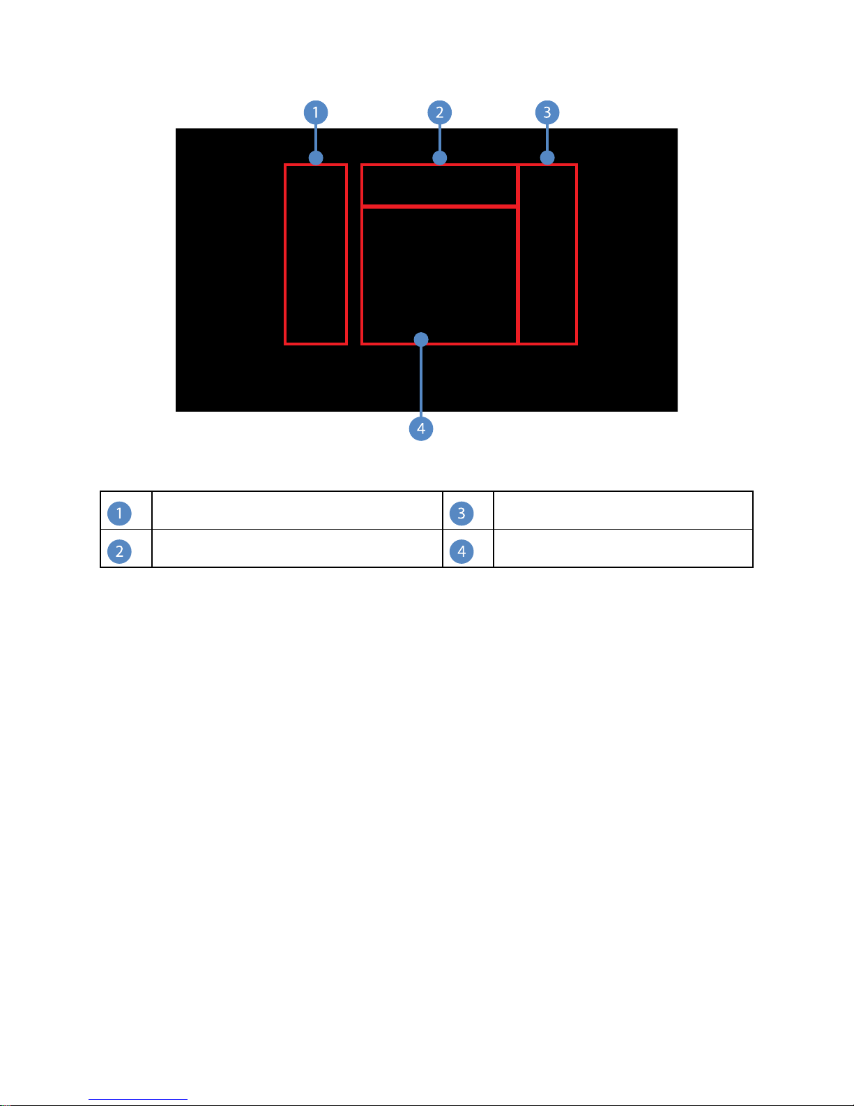
FFiigguurree 77.. SSiimmppllee RRoouuttiinngg MMaaiinn SSccrreeeenn
Sources
Displays
Devices Preview
NNoottee:: TThhee ttoouucchh ppaanneell iiss nnoott lliisstteedd aass aa ssoouurrccee iinn SSiimmppllee RRoouuttiinngg ffoorr AAllll--IInn--OOnnee
ssyysstteemmss..
7.1.1 Viewing a Source on a Display
To view a source on a display, perform the following steps:
1. Select a source (Item 1), such as the Endo Cam, from the Sources area located on
the left side of the screen. The button will turn orange, indicating it has been
selected.
2. Select a display (Item 3), such as Monitor 2, from the Displays area located on the
right side of the screen. The button will turn orange for a few seconds, indicating it
has been selected, and the route has been completed. The icon for the video source
being routed to the display will appear on the display button.
25
Page 28

FFiigguurree 88.. VViieewwiinngg aa SSoouurrccee oonn aa DDiissppllaayy
RRoouuttiinngg TTwwoo SSuuiitteeSSttrreeaammss
If two SuiteStreams are configured, these can be used to route two independent
channels of video during a Room Call. The two SuiteStream devices will appear in both
the Sources and Displays menu. To route a local video source to the far side of the Room
Call, local video sources are routed to these SuiteStream displays in the same way as
when routing to other displays. To route a video source from the far side of the Room
Call, these SuiteStream sources are routed to local displays in the same way as when
routing from other sources.
NNoottee:: AA SSuuiitteeVViieeww DDeesskkttoopp vviieewweerr wwiillll oonnllyy bbee aabbllee ttoo vviieeww aa vviiddeeoo ssoouurrccee tthhaatt hhaass
bbeeeenn rroouutteedd ttoo tthhee ffiirrsstt SSuuiitteeSSttrreeaamm..
7.1.2 Viewing and Recording a Source on a Display
To select a source to view and record on a display, perform the following steps:
1. Select a source, such as the Endo Cam, from the Video Sources area located on the
left side of the screen.
2. Select a recording device through which to route the source, such as the SDC, from
the Devices area at the top of the screen. The icon for the video source being routed
through the device will be displayed on the device button.
3. Select a display, such as Monitor 2, from the Displays area located on the right side
of the screen. The icon for the video source being routed through the display will
appear on the display button.
4. The route has been completed.
26
Page 29

FFiigguurree 99.. VViieewwiinngg aanndd RReeccoorrddiinngg aa SSoouurrccee oonn aa DDiissppllaayy
7.1.3 Using Sidne or SDC3 along with Viewing and Recording a
Source on a Display
To route a source through a device to a display and use Sidne or SDC3, perform the
following steps:
1. Select a source, such as the Endo Cam, from the Video Sources area located on the
left side of the screen.
2. Select the Sidne or SDC3 destination from the Devices area. The icon for the video
source being routed through Sidne or SDC3 will be displayed on the device button.
3. For Sidne only, select a device through which to route the source, such as the SDC,
from the Devices area at the top of the screen. The icon for the video source being
routed through the device will be displayed on the device button.
4. Select a display, such as Monitor 2, from the Displays area located on the right side
of the screen. The icon for the video source being routed through the display will
appear on the display button, and the route has been completed.
27
Page 30
NNoottee::
•• TThhee DDeevviiccee CCoonnttrrooll PPaacckkaaggee oonn tthhee SSDDCC33 mmuusstt bbee iinnssttaalllleedd bbeeffoorree SSPPII wwiillll
sshhooww SSIIDDNNEE ddeevviicceess..
•• WWhheenn aa ssoouurrccee vviiddeeoo iiss bbeeiinngg rroouutteedd oonn SSDDCC HHDD aanndd SSiiddnnee ,, tthhee cchhaaiinn rroouuttee
wwiillll aallwwaayyss ppllaaccee tthhee SSiiddnnee aahheeaadd ooff tthhee SSDDCC HHDD.. IInn tthhee pprreevviioouuss eexxaammppllee,,
tthhee EEnnddoo CCaamm vviiddeeoo wwiillll aallwwaayyss bbee rroouutteedd tthhrroouugghh tthhee SSiiddnnee ((wwhhiicchh aaddddss
tthhee SSiiddnnee iiccoonn oovveerrllaayy oonn tthhee vviiddeeoo)),, tthheenn tthhrroouugghh SSDDCC HHDD ttoo bbee rreeccoorrddeedd,,
aanndd tthheenn iitt wwiillll bbee ddiissppllaayyeedd oonn MMoonniittoorr 22..
•• TThhee oorrddeerr iinn wwhhiicchh tthhee SSDDCC HHDD//UUllttrraa oorr MMoonniittoorr 22 aarree sseelleecctteedd ddooeess nnoott
aaffffeecctt tthhee oorrddeerr iinn wwhhiicchh tthhee vviiddeeoo rroouuttee oorr cchhaaiinn iiss ccrreeaatteedd.. IInn tthhee pprreevviioouuss
eexxaammppllee,, iiff MMoonniittoorr 22 iiss sseelleecctteedd bbeeffoorree sseelleeccttiinngg tthhee SSDDCC HHDD//UUllttrraa,, tthhee
vviiddeeoo ffrroomm tthhee EEnnddoo CCaamm wwiillll ssttiillll bbee ppaasssseedd tthhrroouugghh tthhee SSDDCC HHDD//UUllttrraa
bbeeffoorree bbeeiinngg rroouutteedd ttoo MMoonniittoorr 22..
•• AA uusseerr hhaass tthhee ooppttiioonn ooff rreeccoorrddiinngg aa vviiddeeoo oonn aann SSDDCC HHDD//UUllttrraa.. TThhee uusseerr
aallssoo hhaass tthhee ooppttiioonn ooff uussiinngg tthhee vvooiiccee ccoonnttrrooll ffeeaattuurree ffrroomm SSiiddnnee .. TThhee rreesstt ooff
tthhee aaccttiioonnss,, nnaammeellyy sseelleeccttiinngg aa ssoouurrccee ((ee..gg..,, EEnnddoo CCaamm)) aanndd aa ddiissppllaayy ((ee..gg..,,
MMoonniittoorr 22)),, aarree rreeqquuiirreedd iinn oorrddeerr ttoo vviieeww aa ssoouurrccee oonn aa ddiissppllaayy..
7.2 Visual Routing
To create a video route using the Visual Routing option, press the AAddvvaanncceedd RRoouuttiinngg
button located on the Quick Button Bar (Item 2).
You will be taken to the Advanced Routing page, which contains two tabs: Visual Routing
and Text Routing. The Visual Routing tab is the default tab. This tab contains three main
28
FFiigguurree 1100.. VViissuuaall RRoouuttiinngg
Page 31

sections: the top section shows the current route in progress (Item 1); the lower left
section shows a list of all available sources, devices, and displays (Item 3); the lower
right corner displays the video preview pane (Item 4).
7.2.1 Creating a Visual Route
To create a video route using the Visual Routing option, perform the following steps:
1. Select a source, such as the Endo Cam, from the Sources list on the left side of the
screen (Item 3). The source will be moved from the Sources area up into the Routes
area (Item 1), indicating it is the source you have selected.
2. If you only want to view the source on a display, select one, such as Monitor 1, from
the Displays list (Item 3).
NNoottee:: WWhheenn rroouuttiinngg aa ssoouurrccee ttoo aa ddeevviiccee oorr ddiissppllaayy,, eennssuurree tthhaatt tthhee vviiddeeoo ttyyppeess
ffoorr eeaacchh ccoommppoonneenntt aarree ccoommppaattiibbllee,, ootthheerrwwiissee tthhee rroouuttee wwiillll nnoott bbee ssuucccceessssffuull..
3. If you wish to route the video through a device, such as Sidne or SDC3, select it from
the Devices list, and then select a display.
4. To route a source through two devices, select the source, select each device, and
then select a display.
Each component in the route will appear in the Routes section at the top of the screen
upon selection.
7.2.2 Unrouting a Selection
To unroute an item, select it from the route and press the UUnnrroouuttee button located at the
top right corner of the Advanced Routing page. The selected item will be removed from
the current route. Repeat the procedure to unroute other items.
7.2.3 Saving a Visual Route as a Preset
To save a current route as a preset, press the SSaavvee PPrreesseett button located in the Global
Taskbar. For detailed information on saving a route as a preset,
page 34
.
see 9.2 Saving a Preset,
7.3 Text Routing
7.3.1 Creating a Text Route
To create a video route using the Text Routing option, press the Text Routing tab on the
Advanced Routing page. From this screen you will use drop down menus to select a
source, device, and display to complete the route.
29
Page 32

FFiigguurree 1111.. TTeexxtt RRoouuttiinngg
To begin a new route using the Text Routing option, perform the following steps:
1. Select a source corresponding to the video input you want to record or view from the
“Sources” drop down menu. A white button-like box listing the name of the source
that you selected will appear in the Route in Progress area at the bottom of the
window. The current video image from the selected source will be displayed in the
video preview pane located at the top right corner of the Text Routing window.
2. If desired, select a device to record to or redirect the video image using the “Devices”
drop down menu. The video source will be routed to the selected device, and the
output of that device will be available to route to another device or display.
3. Select a display to view the source or device from the “Displays” drop down menu.
The output from the source will immediately be visible on that display. You can
continue to choose other displays to route the video image to, or select another
source or device and begin the process all over again.
7.3.2 Creating a New Text Route
To create a new text route, press the NNeeww RRoouuttee button located in the middle of the Text
Routing tab on the Advanced Routing page. The current route will be cleared, and the
screen will be ready for the new route.
7.3.3 Saving a Text Route as a Preset
To save a current route as a preset, press the SSaavvee PPrreesseett button located in the Global
Taskbar.
30
Page 33

8
PIP and Quad View Generator Functionality
8.1 PIP
The Picture-in-Picture (PIP)/Picture-by-Picture (PBP) Generator is intended to be used
with the SwitchPoint Infinity 3 Control System, but can be used as a stand alone PIP in
the OR. This feature enables the user to view two images simultaneously on one monitor.
Using this option the user can view one picture in the corner of another, or view two
pictures side-by-side.
To access the PIP/PBP feature, press the PPIIPP button located on the Quick Button Bar.
The Picture-in-Picture screen will open.
FFiigguurree 1122.. PPiiccttuurree--iinn--PPiiccttuurree VViieeww SSccrreeeenn
The OOnn and OOffff buttons at the top of the PIP screen are used to turn the PIP/PBP option
on or off.
8.1.1 Selecting Images
The “Select Image” drop down menus are used to select which images will appear in
positions 1 and 2 of the screen layouts.
8.1.2 Screen Layout
The six buttons located in the Screen Layout box are used to select which layout will be
displayed.
31
Page 34

8.1.3 Swap Images
The SSwwaapp IImmaaggeess button swaps the position of the images on the screen. Pressing this
button cycles the image in position 1 to position 2 and vice versa.
Select Destinations
The “Select Destination” drop down menu allows the user to select where to route the
PIP/PBP image. A preview of the display will appear in the box in the upper right hand
corner of the screen.
8.1.4 PIP Small / PIP Large
The two buttons located in the Inset Size box is used to choose between displaying the
PIP as a large or small image. The large inset will fill up approximately 1/4 of the screen,
and the small inset will fill up approximately 1/9 of the screen.
This option only applies to the PIP feature.
8.2 Quad View
NNoottee:: QQUUAADD vviieeww iiss nnoott aavvaaiillaabbllee ffoorr SSPPII33--LLiittee..
The Quad View Generator enables the ability to simultaneously view four images on one
monitor. Using this option three images can be displayed down one side of the monitor
with one larger image on the opposite side, or view all four images in equal.
The OOnn and OOffff buttons at the top of the Quad screen are used to turn the option on or
off.
32
FFiigguurree 1133.. QQuuaadd VViieeww SSccrreeeenn
Page 35

8.2.1 Selecting Images
The “Select Image” drop down menus are used to select which images will appear in the
screen layout.
8.2.2 Screen Layout
The three buttons located in the Screen Layout section are used to select the image
orientation.
8.2.3 Select Destinations
The “Select Destination” drop down menu is used to select a display to route the image
to. A preview of the display will appear in the box in the upper right hand corner of the
screen.
NNoottee:: IIff iitt bbeeccoommeess nneecceessssaarryy ttoo aaddjjuusstt tthhee oouuttppuutt rreessoolluuttiioonn ffoorr tthhiiss ffeeaattuurree,,
rreeffeerreennccee tthhee IInnssttaallllaattiioonn MMaannuuaall..
33
Page 36

9
Presets
SwitchPoint Infinity 3 provides the ability to save preferred audio, camera, lighting, and
video settings into Presets. They are a time-saving function for remembering frequently
used room configurations. Presets may be sorted into six user-defined groups or left in a
single undefined grouping. The figure below shows one group of presets. To access the
Presets menu, press the PPrreesseettss button on the top left side of the screen.
The SwitchPoint Infinity 3 Control System supports up to 48 presets in each of the six
potential preset groups. If more than seven presets have been configured, a scroll bar
will appear on the right side of the window. The current page number and the number of
pages will appear between the up and down scroll buttons.
9.1 Recalling Presets
To recall a stored preset, press the desired preset button. A message will appear stating,
“Executing Preset. Please Wait.” The preset will then be loaded.
9.2 Saving a Preset
Before storing a new preset, begin by setting up all of the video routing choices, lighting,
camera positions, and audio mixes for the SwitchPoint Infinity 3 Control System.
1. Press the SSaavvee PPrreesseett button located on the Global Taskbar at the bottom of the
screen. The Save Preset screen will open.
34
FFiigguurree 1144.. PPrreesseettss MMeennuu
Page 37

FFiigguurree 1155.. SSaavvee PPrreesseettss SSccrreeeenn
2. Select the white text field or the EEddiitt button next to the “Enter Name” field. A
keyboard screen will appear.
FFiigguurree 1166.. KKeeyybbooaarrdd SSccrreeeenn
3. Enter the preset name using the on-screen keyboard that appears, or the attached
keyboard. The preset name can be no longer than 41 characters, including spaces.
4. Press DDoonnee when finished. The “Enter Name” field will display the new preset name.
5. Select the preset group where you want to save your new preset. If only one preset
group has been configured, it will be selected by default.
6. Select the function(s) that the new preset will control. For example, if this is a video
preset, press the VViiddeeoo button. To save a preset that has video, audio, and camera
settings, select all three buttons.
7. Press the DDoonnee button to save your new preset. To cancel the preset, press the red
XX button at the top right-hand corner of the screen. You will be returned to the
Presets screen.
35
Page 38

9.3 Previewing Presets
The PPrreevviieeww button, located on the right side of any given preset, allows you to preview
the options associated with the particular preset before selecting it for use.
To view a preset, press the PPrreevviieeww button. A Preset Preview screen will open and
display all of the features associated with the specific route.
FFiigguurree 1177.. PPrreesseett PPrreevviieeww SSccrreeeenn
NNoottee:: TThhee PPrreevviieeww bbuuttttoonn ddiissppllaayyss iiccoonnss ffoorr aallll ooff tthhee ffuunnccttiioonnss tthhaatt aarree ccoonnttrroolllleedd
iinn tthhee rreessppeeccttiivvee pprreesseett..
To apply the preset, press the EExxeeccuuttee PPrreesseett button at the bottom right corner of the
screen. To close out of the preview without applying the preset, press the red XX button at
the top right corner of the screen.
9.4 Unrouting Presets
To unroute all presets and functions, press the UUnnrroouuttee EEvveerryytthhiinngg button in the Preset
Menu. All connections will be broken.
36
Page 39

10
Calls
The SwitchPoint Infinity 3 Control System allows room-to-room connectivity for video
conferencing. All connections within the Operating Room Information Systems (ORIS)
are transmitted using broadcast quality audio and video. Offsite connections are
accomplished via the use of a Codec Device.
The SwitchPoint Infinity 3 Control System equipped with ConnectSuite allows room-to-
room connectivity for IP video conferencing using Stryker SuiteLink and a Campus
Codec. In addition, IP broadcasting to the desktop is supported using Stryker SuiteView.
The SwitchPoint Infinity 3 Control System with a Video Network Hub supports manual
dialing of Room-to-Room, Broadcast, and View Only calls along with as IP, ISDN, and
Gateway calls using either the Stryker Video Network Hub or a locally connected Codec.
The SwitchPoint Infinity 3 Control System also can “wait” for an incoming Codec call from
any available Codec, meaning that when a call comes from a specified Codec, the call
will be automatically connected, whereas all other calls will need to be accepted before a
connection is complete.
NNoottee:: IIff yyoouurr ssyysstteemm iiss nnoott eeqquuiippppeedd wwiitthh aa SSuuiitteeLLiinnkk,, VViiddeeoo NNeettwwoorrkk HHuubb,, oorr
llooccaallllyy ccoonnnneecctteedd CCooddeecc,, tthhee CCaallllss mmeennuu aanndd PPrriivvaattee bbuuttttoonnss wwiillll bbee ggrraayyeedd oouutt
aanndd nnoott aacccceessssiibbllee..
In addition to manual dialing, the Calls feature supports one-touch calling of any
connected endpoint from the Campus Status tab, one-touch dialing of the Last 10 Dialed,
and up to 200 presets in the Call Groups tab.
Calls can be made from the Manual Dial, Campus Status, Last 10 Dialed, or Call Groups
interfaces. To access the interface, press the CCaallllss button on the Global Taskbar.
37
Page 40

FFiigguurree 1188.. CCaallllss SSccrreeeenn
Before making a video call to another Stryker endpoint, prepare an image to send out of
the room. This is the image you initially want the far end to see. This image could be a
Room Camera view of the presenter or a wide view of the Operating Room. One video
source can be routed out of the iSuite OR and one video signal can be simultaneously
received from a remote room, via the SuiteLink and the Campus Codec or Video Network
Hub.
The “What you send” and “Where you see it” drop down menus are a convenient way to
route video to and from SuiteLink or to and from the Campus Codec when making a call.
The “What you send” drop down menu contains a list of all configured sources and
devices capable of being routed out of the room. When a source or device is selected
from the “What you send” list, it is previewed in the video preview frame above the drop
down menus. The “Where you see it” drop down menu lists all devices or displays on
which incoming video can be displayed.
When in an active call, the “What you see” drop down menu will be available, and will list
all of the available incoming video endpoints.
10.1 Manual Dial Tab
The Manual Dial tab allows you to make up to four different types of calls, depending on
your system setup, such as Room-to-Room, local Codec, Hub Codec, and Campus
Codec.
For a SuiteLink setup, the Manual Dial tab allows you to initiate a Campus Codec call or
a SuiteLink Hub Codec call if an offsite package is configured.
To access the Manual Dial tab, press the CCaallllss button on the Quick Button Bar and then
press the Manual Dial tab on the Calls screen.
38
Page 41

10.2 Campus Status
The Campus Status screen allows you to view the status of all registered Stryker
endpoints, and provides the ability to call any available endpoint using one-touch dialing.
Available endpoints are shown as “Idle.” Endpoints that are set to Private status are
shown as “Private.” Endpoints that are not currently connected or are powered off appear
grayed-out with an “Offline” status message.
FFiigguurree 1199.. CCaammppuuss SSttaattuuss SSccrreeeenn
To access the Campus Status screen, press the CCaallllss button on the Quick Button Bar
and press the Campus Status sub tab.
Selecting any room from the Campus Status interface will automatically initiate a call with
that room. If the call is successful, you will be taken to the Active Call screen.
NNoottee:: AAcccceessssiinngg tthhee ooffffssiittee CCooddeecc iiss nnoott aavvaaiillaabbllee ffrroomm tthhee ““CCaammppuuss SSttaattuuss””
iinntteerrffaaccee..
10.3 Campus Codec Call
NNoottee:: TThhiiss sseeccttiioonn iiss oonnllyy aapppplliiccaabbllee ttoo ssyysstteemmss wwiitthh SSuuiitteeLLiinnkk aanndd SSuuiitteeVViieeww..
Campus Codec calls allow video to be streamed and made accessible to other
authorized SuiteView users. Campus Codec calls must be initiated from the SPI3 or
SPI3-Lite user interface.
If the default connection speed (medium) is acceptable, it is preferable to use the
Campus Status option (see below) for video conferencing to other Stryker endpoints.
Campus Status allows you to view the current status of all registered endpoints and
make calls with one-touch dialing.
For a SuiteLink setup, the Manual Dial tab allows the ability to override the default
connection speed for Campus Codec calls only.
To make a Campus Codec Call:
39
Page 42

1. Select Campus Codec from the “Connection Type” drop down menu.
FFiigguurree 2200.. MMaakkiinngg aa RRoooomm--ttoo--RRoooomm CCaallll
2. Select the video resolution from the “Connection Speed” drop down menu.
NNoottee:: IIff hhiigghh ssppeeeedd vviiddeeoo rreessoolluuttiioonn iiss sseelleecctteedd,, tthheenn IIPP bbrrooaaddccaassttiinngg ttoo tthhee
ddeesskkttoopp ffrroomm tthhiiss rroooomm wwiillll bbee ddiissaabblleedd..
3. Select which room to connect to from the “Room Name” drop down menu.
4. Press the green CCaallll button under the number pad to make the call.
If the call is successful, you will be taken to the Active Call screen, and the Call Status
bubble will indicate “In Call.”
FFiigguurree 2211.. CCaammppuuss CCooddeecc IInn CCaallll BBuubbbbllee
10.4 Room-to-Room Call
NNoottee:: TThhiiss sseeccttiioonn iiss oonnllyy aapppplliiccaabbllee ttoo ssyysstteemm wwiitthh aa VViiddeeoo NNeettwwoorrkk HHuubb..
To make a video call to another room within the campus:
1. Select Room Call from the “Connection Type” drop down menu.
40
Page 43

FFiigguurree 2222.. MMaakkiinngg aa RRoooomm--ttoo--RRoooomm CCaallll
NNoottee::
•• FFoorr iinn--ddeepptthh iinnffoorrmmaattiioonn oonn llooccaall aanndd VViiddeeoo NNeettwwoorrkk HHuubb CCooddeecc ccaallll,,
1100..1100 OOffffssiittee ((CCooddeecc)) CCaallllss,, ppaaggee 4477
..
•• FFoorr iinn--ddeepptthh iinnffoorrmmaattiioonn oonn BBrrooaaddccaasstt,, VViieeww OOnnllyy,, aanndd MMeeeettiinngg RRoooomm
ccaallll ttyyppeess,,
sseeee 1100..1133 AAddvvaanncceedd CCaallll TTyyppeess,, ppaaggee 5500
..
2. Select the connection method from the “Connection Method” drop down menu.
3. Select which room to connect to from the “Room Name” drop down menu.
4. Press the green CCaallll button under the number pad to make the call.
You will see a brief “Connecting Call” message in the green Call Status bubble in the
upper right-hand corner of the screen. If the call is successful, you will be taken to the
Active Call screen.
NNoottee:: IIff tthhee SSwwiittcchhPPooiinntt IInnffiinniittyy 33 CCoonnttrrooll IInntteerrffaaccee iiss uunnaabbllee ttoo ccoonnnneecctt ttoo tthhee
rreemmoottee rroooomm,, aann eerrrroorr mmeessssaaggee wwiillll aappppeeaarr iinn tthhee CCaallll SSttaattuuss bbuubbbbllee..
sseeee
41
Page 44

10.5 Active Call
FFiigguurree 2233.. AAccttiivvee CCaallll SSccrreeeenn
Near and Far Buttons Hang Up Button
Camera Control Image Selection Drop Down Menus
Call Status Bubble
The Active Call page is displayed automatically after a call is connected. The Call Status
bubble will indicate whether the room is in a call, either with a Desktop User or with a
room. If the room is not in a call with either a Desktop User or another room, no bubble
will appear.
The NNeeaarr and FFaarr buttons on the Active Call screen are used to select which camera to
control during a call. The camera controls work in the same manner as the Room
Camera controls on the Room Camera interface.
The “What you send” and “Where you see it” drop down menus are convenient ways to
route video to and from the remote connection. The “What you send” option on the Active
Call screen displays a preview of the image being sent to the remote room’s local
display. When the far video is selected, the video preview pane will display the remote
image.
The “What you send” drop down menu contains a list of all configured sources and
devices for routing to the remote connection.
The “What you see” drop down menu lists all video sources from the remote room.
42
Page 45

The “Where you see it” drop down menu contains a list of all devices and displays on
which incoming video can be displayed.
Touch the preview screen to expand the preview window to a larger size. Press the red XX
in the top right corner of the preview window to return to the normal user interface.
To allow the user on the other end to control the camera, select the “Allow others to
control my camera” box. This will enable the user to pan, tilt, and zoom the camera.
To disconnect a call, press the red HHaanngg UUpp button on the Active Call page. When a call
is disconnected, the screen will return to the interface from which the call was initiated.
10.5.1 Active Call Status
NNoottee:: TThhiiss sseeccttiioonn iiss oonnllyy aapppplliiccaabbllee ttoo ssyysstteemmss wwiitthh aa VViiddeeoo NNeettwwoorrkk HHuubb..
To view the participants and status of the current call, press the CCaallll SSttaattuuss button
located in the lower middle portion of the screen. The Active Call Status screen will open.
FFiigguurree 2244.. AAccttiivvee CCaallll SSttaattuuss SSccrreeeenn
Depending on the type of call you are involved in, call information will be displayed in one
of the three sections of the Active Call Screen.
• IInn CCaallll WWiitthh - Shows all of the participants on a call other than one where you are
the recipient or on a conference call, with a maximum of three connections.
• VViieewwiinngg FFrroomm - Shows the other participant on a View Only call.
• BBrrooaaddccaassttiinngg TToo - Shows all of the participants on a broadcast call.
NNoottee:: WWhheenn eennddiinngg aa ccaallll,, yyoouu mmuusstt pprreessss tthhee HHaanngg UUpp bbuuttttoonn ffoorr eeaacchh ppaarrttiicciippaanntt..
HHaannggiinngg uupp oonn tthhee ccaallll ffrroomm tthhee AAccttiivvee CCaallll ssccrreeeenn,, aass ooppppoosseedd ttoo tthhee AAccttiivvee CCaallll
SSttaattuuss ssccrreeeenn,, wwiillll oonnllyy ddiissccoonnnneecctt yyoouu ffrroomm tthhee ccaallll.. IItt wwiillll nnoott ddiissccoonnnneecctt aallll
ppaarrttiieess..
43
Page 46

10.6 Private
CCaauuttiioonn::
• Selecting the Private feature automatically disconnects any room connection.
• In order to comply with the privacy provisions of the Health Insurance Portability
and Accountability Act of 1996 (HIPAA), “Private” must be turned ON when not
actively engaged in a teleconference with another room within the OR or with
offsite locations.
If your room is not set to “Private” and somebody attempts to call you, the connection will
be made automatically.
The PPrriivvaattee button, located in the bottom left corner of the Global Taskbar, provides
control over who can view or remotely monitor the room where the SwitchPoint Infinity 3
Control System is located. The PPrriivvaattee button toggles on and off and stays highlighted in
orange when Private is On. If Private is On, the system restricts all inbound
communications. If the SwitchPoint Infinity 3 Control system is currently connected to
another room within the hospital campus or offsite location, activating the Private feature
will immediately disconnect the room.
When Private is On, you can still make outgoing calls to other rooms. The Private “On”
state is restored after the call.
If you attempt to connect to a room that is “In Private” the call must be accepted by the
callee. If nobody accepts the call, the CCaallllss SSttaattuuss button on the top right corner of the
screen will display the text “Call Failed. Touch to Cancel.” or “Remote Room is Private.”
If your room is “In Private” and somebody attempts to call, the Calls Status button will
appear on the top right corner of the screen displaying the text ,“Touch to Accept” or
“Incoming Call. Press to Accept” accompanied by an audible alert.
10.7 Last 10 Dialed
NNoottee:: BBeeffoorree sseelleeccttiinngg aann eennttrryy oonn tthhee LLaasstt 1100 DDiiaalleedd ssccrreeeenn,, pprreeppaarree tthhee oouuttggooiinngg
vviiddeeoo ssiiggnnaall wwiitthh tthhee ““WWhhaatt yyoouu sseenndd”” aanndd ““WWhheerree yyoouu sseeee iitt”” ddrroopp ddoowwnn mmeennuuss..
The Last 10 Dialed call screen displays the last 10 room or offsite calls made from that
endpoint.
To access the Last 10 Dialed screen, press the CCaallllss button on the Quick Button Bar,
and then press the Last 10 Dialed sub tab.
44
Page 47

FFiigguurree 2255.. LLaasstt 1100 DDiiaalleedd CCaallllss SSccrreeeenn
Any endpoint or remote site displayed on the Last 10 Dialed screen can be dialed with
one-touch dialing by pressing the entry. The SwitchPoint Infinity 3 Control System will
automatically attempt to connect to the destination. If the call is successful, you will be
taken to the Active Call screen.
10.8 Call Groups
The Call Groups tab provides call-specific presets for call types available from the
SwitchPoint Infinity 3 Control Interface. Once a Preset is stored in the Call Groups
section, the call can be placed using one-touch dialing from the Call Groups tab.
FFiigguurree 2266.. CCaallll GGrroouuppss SSccrreeeenn
45
Page 48

NNoottee:: BBeeffoorree ssttoorriinngg aa nneeww PPrreesseett iinn tthhee CCaallll GGrroouuppss sseeccttiioonn,, eenntteerr tthhee ccoonnnneeccttiioonn
ttyyppee,, ddiiaalliinngg nnuummbbeerr,, aanndd aannyy ootthheerr nneecceessssaarryy ccaalllliinngg iinnffoorrmmaattiioonn iinn tthhee MMaannuuaall
DDiiaall iinntteerrffaaccee aanndd pprreessss tthhee SSttoorree NNuummbbeerr bbuuttttoonn..
10.9 Storing a Speed Dial Call Setting
To store a Speed Dial Call setting:
1. Select all of the applicable settings necessary to make a call from the Manual Dial
tab.
2. Press the SSttoorree NNuummbbeerr button located at the bottom left corner of the screen. The
Store Number screen will open.
FFiigguurree 2277.. SSttoorree NNuummbbeerr SSccrreeeenn
3. Select the white text field or the EEddiitt button next to the Enter Name field.
• Enter the preset name using the on-screen or attached keyboard. The preset
name can be no longer than 13 characters, including spaces.
• Press DDoonnee when finished. The Enter Name field will display the new preset
name.
• The interface will return to the Store Number screen.
4. Select the Calls Group in which to store the speed dial call setting.
5. Press DDoonnee.
The SwitchPoint Infinity 3 Control System supports up to 50 speed dial call settings in
each of the four call groups. If more than four speed dial call settings have been
configured, a scroll bar will appear on the right side of the screen. The current page
number and the number of pages will appear between the up and down scroll buttons.
Select any speed dial call setting to one-touch dial the stored location. After selecting a
speed dial call setting, the interface will automatically navigate to the Active Call screen.
46
Page 49

10.10Offsite (Codec) Calls
Offsite or Codec calls can be initiated from the Manual Dial screen as well as the Last 10
Dialed and Call Groups interfaces.
FFiigguurree 2288.. MMaakkiinngg aa CCooddeecc CCaallll
Up to six different types of offsite calls are available, depending on the options available
on the Codec and whether there is a local Codec or one or more Video Network Hub
Codec(s) available.
10.11Making a Codec IP Call
To dial a Hub Codec IP or Local Codec IP call:
1. From the Manual Dial tab, select the call type from the “Connection Type” drop down
menu.
2. Select the connection method from the “Connection Method” drop down menu.
3. Select the call “speed” or bandwidth from the “Connection Speed” drop down menu.
4. Select the Codec to be used from the “Codec Name” drop down menu.
5. Enter the IP address using the on-screen keypad.
6. Press the green CCaallll button located below the number pad to initiate the call.
NNoottee:: PPrreessss tthhee SSttoorree NNuummbbeerr bbuuttttoonn ttoo ssttoorree tthhee ccaallll iinnffoorrmmaattiioonn ttoo CCaallll GGrroouuppss
pprreesseettss..
10.11.1Making a Codec ISDN Call
NNoottee:: TThhiiss sseeccttiioonn iiss oonnllyy aapppplliiccaabbllee ttoo ssyysstteemmss wwiitthh aa VViiddeeoo NNeettwwoorrkk HHuubb..
To dial a Hub Codec ISDN or Local Codec ISDN call:
1. From the Manual Dial tab, select the call type from the “Connection Type” drop down
menu.
2. Select the Codec to be used from the “Codec Name” drop down menu.
47
Page 50

3. Select the call “speed” or bandwidth from the “Connection Speed” drop down menu.
4. Enter the ISDN phone number using the on-screen keypad (no dashes required).
5. Press the green CCaallll button to initiate the call.
NNoottee:: PPrreessss tthhee SSttoorree NNuummbbeerr bbuuttttoonn ttoo ssttoorree tthhee ccaallll iinnffoorrmmaattiioonn ttoo CCaallll GGrroouuppss
pprreesseettss..
10.11.2Making a Codec Gateway Call
NNoottee::
•• TThhiiss sseeccttiioonn iiss oonnllyy aapppplliiccaabbllee ttoo ssyysstteemmss wwiitthh aa VViiddeeoo NNeettwwoorrkk HHuubb..
•• AA ggaatteewwaayy ccaallll iiss oonnllyy uusseedd iiff tthhee eennvviirroonnmmeenntt ccoonnttaaiinnss aa ssppeecciiaalliizzeedd HH..332200//
HH..332233 ggaatteewwaayy ddeevviiccee.. CChheecckk wwiitthh yyoouurr llooccaall IITT ddeeppaarrttmmeenntt ffoorr iinnffoorrmmaattiioonn
oonn uussiinngg tthhiiss ddeevviiccee,, aass iitt mmaayy rreeqquuiirree ccuussttoomm ccoonnffiigguurraattiioonn aanndd ddiiaalliinngg
ssttrriinnggss..
To dial a Hub Codec Gateway or Local Codec Gateway call:
1. From the Manual Dial tab, select the call type from the “Connection Type” drop down
menu.
2. Select the Codec to be used from the “Codec Name” drop down menu.
3. Select the call “speed” or bandwidth from the “Connection Speed” drop down menu.
4. Enter the gateway prefix (if required) and phone number using the on-screen keypad
(no dashes required).
5. Press the green CCaallll button to initiate the call.
NNoottee:: PPrreessss tthhee SSttoorree NNuummbbeerr bbuuttttoonn ttoo ssttoorree tthhee ccaallll iinnffoorrmmaattiioonn ttoo CCaallll GGrroouuppss
pprreesseettss..
10.11.3Waiting for an Offsite Call
The SwitchPoint Infinity 3 Control System can wait for an incoming Codec call from a
specific Codec connected to the system.
To wait for a specific incoming Codec call:
1. Press the Manual Dial tab.
2. Select WWaaiitt ffoorr OOffffssiittee CCaallll from the “Connection Method” drop down menu.
After the Codec is selected, the Control System places you in the Active Call interface
with focus on the selected Codec. When the incoming call is connected by the Codec,
the call will be complete. Use the HHaanngg UUpp button to cancel Wait for an Offsite Call or to
end a completed call.
NNoottee:: AA WWaaiitt ffoorr aann OOffffssiittee CCaallll wwiillll ttiimmee oouutt aafftteerr 3300 mmiinnuutteess iiff aa ccaallll hhaass nnoott bbeeeenn
rreecceeiivveedd..
48
Page 51

10.12Managing SuiteView Functionality
The SwitchPoint Infinity 3 Control System allows room-to-room connectivity for IP video
conferencing using Stryker SuiteLink and a Campus Codec. In addition, IP broadcasting
to the desktop is supported using Stryker SuiteView.
NNoottee:: IIff yyoouurr ssyysstteemm iiss nnoott eeqquuiippppeedd wwiitthh aa SSuuiitteeLLiinnkk SSeerrvveerr tthhee CCaallllss mmeennuu aanndd
PPrriivvaattee bbuuttttoonnss wwiillll bbee ggrraayyeedd oouutt aanndd nnoott aacccceessssiibbllee..
10.12.1Desktop User Access
Clicking on the Desktop Users button opens the Desktop Users menu that shows what
users are viewing your endpoint.
Desktop Viewers
Desktop Users Button
The top of the Desktop Users panel displays a list of all users who are actively viewing
the feed.
If the call is being viewed by a desktop user, this will be indicated by the Desktop Call
bubble in the upper right corner of the screen.
10.12.2Managing Call Settings
To manage Viewer settings, click the EEddiitt UUsseerr SSeettttiinnggss button at the bottom of the
Desktop Users menu.
FFiigguurree 2299.. DDeesskkttoopp UUsseerrss MMeennuu
Edit Caller Setting Button
Call Status Bubble
49
Page 52

FFiigguurree 3300.. VViieeww SSeettttiinnggss MMeennuu
To allow users to control the camera, click in the respective box. An orange, checked box
indicates this setting is active.
To allow users to users to control the video sources they view, click in the respective box.
An orange, checked box indicates this setting is active.
To choose the video source to route to users, select it from the “What you Send” drop
down menu.
To return to the main Desktop Users menu, click the BBaacckk ttoo UUsseerrss button.
10.13Advanced Call Types
NNoottee:: TThhiiss sseeccttiioonn iiss oonnllyy aapppplliiccaabbllee ttoo ssyysstteemmss wwiitthh aa VViiddeeoo NNeettwwoorrkk HHuubb..
Broadcast and View call types allow a single direction video and audio call. The
broadcasting endpoint initiates a broadcast call and can select multiple endpoints to
broadcast to. Endpoints can also choose to participate in a broadcast call already in
progress by using the View call feature. Every endpoint connected to the Stryker hub can
view a Broadcast call.
10.13.1Broadcast
A Broadcast call is initiated from the Manual Dial interface or can be stored as a preset
and initiated from the Call Groups interface. To create a Broadcast call do the following:
1. Navigate to the Manual Dial interface and select Room Call from the “Connection
Type” drop down menu.
2. Select Broadcast from the “Connection Method” drop down menu.
3. Select an endpoint from the “Room Name” drop down menu.
4. Press the green CCaallll button to initiate the call.
50
Page 53

To select another endpoint(s) to broadcast to, repeat the above procedure for each
endpoint, selecting that endpoint name from the “Room Name” drop down menu.
To disconnect a Broadcast call, press the red HHaanngg UUpp button on the Active Call
interface.
10.13.2View Only
A View Only call is initiated from the Manual Dial interface or can be stored as a preset
and initiated from the Call Groups interface.
To create a View Only call:
1. Navigate to the Manual Dial interface and select Room Call from the “Connection
Type” drop down menu.
2. Select View Only from the “Connection Method” drop down menu.
3. Select the endpoint that is broadcasting from the “Room Name” drop down menu.
4. Press the green CCaallll button to initiate the View Only call.
An endpoint can only view one broadcast call at a time.
To disconnect from a View Only call, press the red HHaanngg UUpp button on the Active Call
interface.
10.13.3Meeting Room
The Meeting Room call feature is only available on an ORIS equipped with a Video
Network Hub that has the Meeting Room option installed. If these features are available
within the ORIS, the SwitchPoint Infinity 3 Control System is automatically capable of
using them, and no additional configuration is necessary.
A Meeting Room call is any call that consists of more than two endpoints exchanging
two-way audio and video. The Meeting Room call feature supports a maximum of four
endpoints. It is capable of using the Codec within the Video Network Hub as one
endpoint, allowing up to three local and one remote endpoint to participate in a Meeting
Room call.
A Meeting Room call is initiated from the Manual Dial interface or can be stored as a
preset and initiated from the Call Groups interface.
To create a Meeting Room call:
1. Navigate to the Manual Dial interface and select Room Call from the “Connection
Type” drop down menu.
2. Select Broadcast from the “Connection Method” drop down menu.
3. Select the first endpoint that is participating in the Meeting Room call from the “Room
Name” drop down menu.
4. Press the green CCaallll button to initiate the call.
5. Navigate to the Manual Dial interface and repeat the above steps until all desired
endpoints are connected to the Meeting Room call.
51
Page 54

A Codec can be added to the Meeting Room call by selecting a Codec Call type from the
“Connection Type” drop down menu and dialing a Codec call. For information on dialing
Codec calls,
see 10.10 Offsite (Codec) Calls, page 47
.
A Meeting Room call can be disconnected by pressing the red HHaanngg UUpp button from the
Active Call interface.
NNoottee:: AAllll eennddppooiinnttss mmuusstt ddiissccoonnnneecctt ffrroomm aa MMeeeettiinngg RRoooomm ccaallll iinnddiivviidduuaallllyy..
DDiissccoonnnneeccttiinngg oonnllyy tthhee ccaallll oorriiggiinnaattoorr ddooeess nnoott eenndd tthhee ccaallll..
52
Page 55

11
Surgical Timeout
Surgical Timeout provides the opportunity for all members of the operating room team to
review the case of the patient before a surgical procedure begins. The timeout checklist
assists in identifying any inconsistencies and helps prevent errors in the operating room.
Additionally, it improves overall communication between members of the team. The
purpose of the SwitchPoint Infinity Surgical Timeout functionality is to assist with the
implementation of the Joint Commission Universal Protocol for the Prevention of Wrong
Site, Wrong Procedure, and Wrong Person Surgery.
The checklist is customizable and can be modified to include practice-specific
components, as well as eliminate components that are deemed unnecessary.
No alarms or other warnings are associated with this checklist.
11.1 Surgical Timeout Procedure
NNoottee:: IItt iiss rreeccoommmmeennddeedd tthhaatt aa nneeww ppaattiieenntt ccaassee iiss ccrreeaatteedd aanndd tthhee ppaattiieenntt
iinnffoorrmmaattiioonn iiss aaddddeedd oonn tthhee SSDDCC bbeeffoorree ppeerrffoorrmmiinngg aa SSuurrggiiccaall TTiimmeeoouutt aanndd
pprriinnttiinngg tthhee SSuurrggiiccaall TTiimmeeoouutt CChheecckklliisstt.. TThhiiss wwiillll eennssuurree tthhaatt tthhee ppaattiieenntt
iinnffoorrmmaattiioonn iiss oonn tthhee pprriinntteedd ddooccuummeenntt..
To begin the Surgical Timeout, do the following:
1. Press the TTiimmeeoouutt button on the Quick Button Bar.
FFiigguurree 3311.. SSuurrggiiccaall TTiimmeeoouutt BBeeggiinnnniinngg SSccrreeeenn
2. Verify that the date and time are correct. If they are, press the YYeess button. If they are
not, press the EEddiitt button in the top right corner of the screen and correct the time
see 21 Setting the Date and Time, page 71
(
).
53
Page 56

3. Once the YYeess button has been pressed, the SSttaarrtt button in Step 2 will become
active. Press it to commence the timeout.
All of the active displays in the OR will display the count down screen, which will
count down from three before displaying the Verification Screen. The room will
automatically be set to “Private” during the timeout.
FFiigguurree 3322.. SSuurrggiiccaall TTiimmeeoouutt CCoouunntt DDoowwnn
FFiigguurree 3333.. SSuurrggiiccaall TTiimmeeoouutt VVeerriiffiiccaattiioonn SSccrreeeenn
4. The Surgical Timeout Verification screen will run the user through the OR’s specific
checklist before being able to begin any surgical procedure. For each step, select
either the YYeess, NNoo, or NN//AA button to proceed to the next question. Once a response
has been selected, it will be marked with a timestamp.
54
Page 57

NNoottee::
•• IItt iiss nnoott ppoossssiibbllee ttoo lleeaavvee aann aannsswweerr bbllaannkk.. EEaacchh qquueessttiioonn mmuusstt bbee
aannsswweerreedd ttoo pprroocceeeedd ttoo tthhee nneexxtt..
•• IItt iiss nnoott ppoossssiibbllee ttoo ggoo bbaacckk aanndd mmooddiiffyy aannsswweerrss.. TToo cchhaannggee aann aannsswweerr,,
yyoouu mmuusstt rreessttaarrtt tthhee vveerriiffiiccaattiioonn bbyy pprreessssiinngg tthhee SSttaarrtt OOvveerr bbuuttttoonn iinn tthhee
uuppppeerr lleefftt ccoorrnneerr ooff tthhee ssccrreeeenn..
5. Once all of the questions have been answered, a Surgical Timeout Verification
Summary will appear that can then be printed out and placed with the patient’s chart.
To print out the summary, press the PPrriinntt ffrroomm SSDDCC button at the bottom right
corner of the screen.
FFiigguurree 3344.. SSuurrggiiccaall TTiimmeeoouutt VVeerriiffiiccaattiioonn SSuummmmaarryy
6. A print-friendly version of the checklist will appear if there is a second touch panel
connected (this feature is not available for SPI 3.5). It will contain fields at the bottom
of the checklist for signatures and notes that can be filled in on the printed form.
FFiigguurree 3355.. SSuurrggiiccaall TTiimmeeoouutt PPrriinntt--FFrriieennddllyy VVeerriiffiiccaattiioonn SSuummmmaarryy
55
Page 58

7. Should the checklist need to be aborted at any time, press the red XX at the top right
corner of the screen. A confirmation screen will appear.
FFiigguurree 3366.. AAbboorrtt SSccrreeeenn
8. To abort the procedure, press the YYeess button. To cancel and return to the procedure,
press the NNoo button.
NNoottee:: FFoorr iinnffoorrmmaattiioonn oonn eeddiittiinngg tthhee SSuurrggiiccaall TTiimmeeoouutt,, rreeffeerr ttoo tthhee IInnssttaallllaattiioonn
MMaannuuaall..
56
Page 59

12
Control Panel
The Control Panel displays all PC Controls, Device Controls, and Advanced Controls
devices that are connected to the SwitchPoint Infinity 3 Control System. For example, the
AAddvvaanncceedd RRoouuttiinngg button controls all of the routing functions within the room while the
RRoooomm CCaammeerraa button sets up and operates the pan/tilt/zoom cameras located within the
room. To access the main Control Panel screen, press the CCoonnttrroollss button on the Quick
Button Bar.
FFiigguurree 3377.. CCoonnttrrooll PPaanneell
The Device Controls section shows buttons for surgical devices such as the Endoscopic
Camera, Insufflator, Light Source, Shaver, and Arthroscopy Pump that are controlled by
the optional SDC3 or Sidne Voice Activation System Voice Package. This section will not
display any device buttons if your system is not equipped or configured with an SDC3 or
Sidne. If there is an SDC3 or Sidne configured but it is turned off or the network is down,
the text “Sidne Not Connected” will be displayed in the Device Controls section. If there is
an SDC3 or Sidne configured and it is turned on but is not communicating with the
SwitchPoint Infinity 3 software, the surgical devices will not be able to be controlled
through the Touch Panel, but can still be controlled via the SDC3 or Sidne voice control,
if available.
The Advanced Controls section features buttons for Advanced Routing, Audio Levels,
Display, PIP/PBP, Quad View, Room Camera, and the Surgical Timeout functions.
57
Page 60

13
PC Device Control
The PC Device Control feature enables the SwitchPoint Infinity 3 Control System to act
as a Keyboard, Video, Mouse (KVM) switch, allowing up to three PCs to share the
SwitchPoint Infinity 3 keyboard, mouse, and monitor.
The SwitchPoint Infinity 3 Control System interface can be configured with one-touch
buttons for a Picture Archiving and Communication System (PACS) PC, a Navigation
(NAV) PC, and an Auxiliary (AUX) PC. Press the button on the SwitchPoint Infinity 3
Control System Home screen for the target PC to be controlled.
The monitor will now display the output of the target PC, and the keyboard and mouse
will control the target PC. Control is returned to the SwitchPoint Infinity 3 Control System
by pressing the red XX in the upper right corner of the screen. The mouse will have no
effect on the red XX.
NNoottee:: TThhee TToouucchh PPaanneell ffuunnccttiioonnaalliittyy ddooeess nnoott ccoonnttrrooll ttaarrggeett PPCCss..
58
Page 61

14
Audio Controls
14.1 Speaker Controls
The Speaker Controls tab on the Audio Levels screen provides the ability to control the
speaker volume as well as change the bass, balance, and treble levels of the SwitchPoint
Infinity 3 Control System Audio Amplifier/Mixer. To access the Speaker Controls screen,
press the AAuuddiioo button from the Quick Button Bar.
The Speaker Control tab has a volume level indicator bar to show the current speaker
volume setting. To adjust the volume, press the “--” or “++” buttons to decrease or increase
the speaker volume, respectively. The MMuuttee button in the center of the level indicator bar
will turn off the audio source for the speaker. The MMuuttee button toggles on and off and
stays highlighted in orange when muted.
FFiigguurree 3388.. SSppeeaakkeerr CCoonnttrroollss SSccrreeeenn
14.2 Input Levels
The Input Levels tab on the Audio Level screen provides the ability to change the audio
input levels, such as the surgeon’s wireless microphone. The SwitchPoint Infinity 3
Control System router supports up to 10 audio inputs, and the SPI3-Lite router supports
up to four inputs. To access the Input Levels tab, press the AAuuddiioo button from the Quick
Button Bar, and press the Input Levels sub tab.
Each audio input level has a volume level indicator bar to show its current settings. To
adjust the volume, press the “--” or “++” buttons to decrease or increase the audio input
volume, respectively. The MMuuttee button in the center of each level indicator bar will turn
59
Page 62

off the audio source for the specific audio input. The MMuuttee button toggles on and off and
stays highlighted in orange when muted.
Up to four audio input buttons can be displayed on the Input Levels tab. If more than four
audio inputs have been configured, a scroll bar will appear on the right side of the screen.
The current page number and the number of pages will appear between the up and down
scroll buttons.
FFiigguurree 3399.. IInnppuutt LLeevveellss SSccrreeeenn
14.3 Output Levels
The Output Levels screen provides the ability to change the audio output levels. The
SwitchPoint Infinity 3 Control System router supports up to 10 audio outputs and the
SPI3-Lite router supports up to four outputs, including two outputs for the speakers. To
access the Output Levels screen, press the AAuuddiioo LLeevveellss button on the Quick Button
Bar and press the Output Levels sub tab.
Each audio output level has a volume level indicator bar to show its current settings. To
adjust the volume, press the “--” or “++” buttons to decrease or increase the audio output
volume, respectively. The MMuuttee button in the center of each level indicator bar will turn
off the audio source for the specific audio output. The MMuuttee button toggles on and off and
stays highlighted in orange when muted.
Up to four audio output buttons can be displayed on the Output Levels tab. If more than
four audio outputs have been configured, a scroll bar will appear on the right side of the
screen. The current page number and the number of pages will appear between the up
and down scroll buttons.
60
Page 63

FFiigguurree 4400.. OOuuttppuutt LLeevveellss SSccrreeeenn
61
Page 64

15
Display
The Displays screen shows all of the configured displays in one location. Each tab on the
Displays screen represents a display in the OR. From each tab you can turn on or off the
display, as well as select the image you want to view on that display.
FFiigguurree 4411.. DDiissppllaayyss SSccrreeeenn
To turn a display on or off, press the PPoowweerr button. To choose a display image, select
one from the “Set Display Image” drop down menu.
62
Page 65

16
Room Camera
The Room Camera screen directs the operation of the wall-mounted pan/tilt/zoom
cameras in the OR. This screen allows the user to adjust the pan/tilt/zoom functions as
well as focus the camera to frame the action. Each camera can be panned left or right,
tilted up and down, and zoomed in and out. The Focus can be controlled automatically by
selecting the AAuuttoo FFooccuuss button, but can be adjusted manually for unusual lighting
conditions or camera angles.
To go to the Room Camera screen, press the RRoooomm CCaamm button in the Quick Button
Bar.
To access the pan/tilt/zoom camera controls:
1. Select one of the available room cameras from the sub tabs at the top of the screen.
2. Direct the camera by pressing and holding the button that corresponds to the desired
direction you want the camera to pan or tilt. For example, press and hold the left
arrow button to move the camera head from right to left. The Zoom and Focus
controls operate in the same manner.
Once the camera angles and zoom preferences have been established, it can be saved
as a preset by pressing and holding down one of the five preset buttons until the
message, “Position has been saved” appears just below the preset buttons.
To recall a saved camera position, press the numbered button (i.e., Position 1) that
corresponds to the camera preset. The camera will return to that position.
FFiigguurree 4422.. RRoooomm CCaammeerraa SSccrreeeenn
63
Page 66

Use the “Set Camera Display” drop down menu to choose a display on which the camera
video will appear.
16.1 Advanced
From the Advanced Room Camera screen the exposure of the image viewed on the
room camera can be adjusted.
FFiigguurree 4433.. AAddvvaanncceedd RRoooomm CCaammeerraa SSccrreeeenn
1. To manually adjust the exposure of the room camera, press the “++” or “--” buttons
under the Manual Settings.
2. To have the camera automatically adjust the settings, press the AAuuttoo button under
the Manual settings.
3. To adjust the white balance, press the “++” or “--” buttons under the White Balance
settings.
4. Depending on the camera, it may be possible to add a text overlay. To do so, press
the OOnn button in the Overlay settings box, and press the EEddiitt button to enter text. If
the camera does not support this feature, it will be disabled.
64
Page 67

17
Remote Device Control
17.1 Stryker Digital Capture (SDC)
SwitchPoint Infinity 3 provides the ability to control the SDC, even without the presence
of a Sidne device. This feature requires SDC Ultra with software version 5.0 or higher or
SDC3. The SDC can still be controlled through the Sidne integration. The SDC3 may be
configured with integrated device control.
NNoottee:: TThhee SSDDCC ttoouucchhssccrreeeenn iiss ssttiillll aaccttiivvee eevveenn wwhheenn iitt iiss bbeeiinngg ccoonnttrroolllleedd bbyy tthhee
TToouucchh PPaanneell eevveenn tthhoouugghh tthhee SSDDCC ttoouucchhssccrreeeenn iiss bbllaacckk.. TToouucchhiinngg tthhee SSDDCC
ttoouucchhssccrreeeenn wwhheenn iitt iiss bbeeiinngg ccoonnttrroolllleedd bbyy tthhee SSwwiittcchhPPooiinntt IInnffiinniittyy ssooffttwwaarree mmaayy
ccaauussee iinnaaddvveerrtteenntt uussee..
NNoottee:: TThhee SSPPII33 ccaannnnoott bbee ccoonnffiigguurreedd wwiitthh aann SSDDCC33 wwiitthh iinntteeggrraatteedd ddeevviiccee ccoonnttrrooll
aanndd aa SSiiddnnee ddeevviiccee..
65
Page 68

18
Observation Room
NNoottee:: SSyysstteemmss rruunnnniinngg SSPPII33..55 ddoo nnoott hhaavvee tthhee OObbsseerrvvaattiioonn RRoooomm ooppttiioonn..
The Observation Room screen controls the speaker volume and video routing for
displays in the observation room. The Observation Room PC will automatically display
this screen when turned on.
FFiigguurree 4444.. OObbsseerrvvaattiioonn RRoooomm SSccrreeeenn
To access the Observation Room screen From SwitchPoint Infinity 3, press the
OObbsseerrvvaattiioonn RRoooomm button under the Advanced Controls section of the Control Panel.
This screen appears similar to the one on the Observation Room PC with the exception
of the DDiissaabbllee button.
66
Page 69

FFiigguurree 4455.. OObbsseerrvvaattiioonn RRoooomm SSccrreeeenn FFrroomm SSwwiittcchhPPooiinntt IInnffiinniittyy 33
To prevent the Observation Room PC from viewing the OR room cameras, press the
DDiissaabbllee button.
18.1 Routing Video
To route video, select a source corresponding to the video input to view from the “Set
Display Image” drop down menu. The output from the source will immediately be visible
on that display.
18.2 Adjusting the Speaker Volume
To adjust the speaker volume, press the “--” and “++” buttons to decrease or increase the
volume, respectively, in the observation room. The MMuuttee button in the center will turn off
the audio for the speaker. The MMuuttee button toggles on and off and stays highlighted in
orange when muted.
NNoottee:: AA sseeccoonndd oobbsseerrvvaattiioonn rroooomm ddiissppllaayy mmaayy oorr mmaayy nnoott bbee ccoonnffiigguurreedd ffoorr aallll
ssyysstteemmss..
18.3 Adjusting the Pan/Tilt/Zoom
For detailed information on using the Pan/Tilt/Zoom features,
page 63
.
18.4 Advanced
For detailed information on the Advanced screen,
see 16 Room Camera,
see 16.1 Advanced, page 64
.
67
Page 70

19
Room Lights
The Room Lights screen directs the operation of the Lutron Lights control. To access this
screen press the RRoooomm LLiigghhttss button under the Advanced Controls section of the
Controls Screen.
The Room Lights screen contains four buttons to trigger the four pre-programmed
presets on the Room Lights Controller, as well as one button to turn off all lights. When a
button is pressed, the room lights will adjust to the correct level for that preset.
Any of the five presets can be saved in a preset on the Presets page; however, the Room
Lights presets themselves are not configurable.
NNoottee:: TThhee RRoooomm LLiigghhtt CCoonnttrroolllleerr WWaallll PPaanneell sshhoouulldd nnoott bbee uusseedd ttoo cchhaannggee rroooomm
lliigghhttiinngg iiff tthhiiss ooppttiioonn iiss iinnssttaalllleedd..
68
FFiigguurree 4466.. RRoooomm LLiigghhttss SSccrreeeenn
Page 71

20
Calibrating the Touch Panel
NNoottee:: CCaalliibbrraattiioonn iiss nnoott rreeqquuiirreedd ffoorr AAllll--IInn--OOnnee ssyysstteemmss.. RRuunnnniinngg ccaalliibbrraattiioonn ffoorr
AAllll--IInn--OOnnee ssyysstteemmss iiss ffoorr aa sseeccoonnddaarryy ttoouucchh ppaanneell oonnllyy..
It may become necessary to calibrate the Touch Panel at some point, such as when
replacing it. Calibration is also necessary when the monitor responds incorrectly to touch.
NNoottee:: TThhee ccaalliibbrraattiioonn ssccrreeeennss mmaayy llooookk ddiiffffeerreenntt tthhaann tthhee ffiigguurreess iinn tthhiiss sseeccttiioonn..
To calibrate the Touch Panel:
1. Press CCTTRRLL + AALLTT + CC.
2. A DOS window will appear, and the calibration session will begin.
CCaauuttiioonn:: DO NOT close the DOS window, as this will interrupt the calibration
process and can cause the calibration to fail. If this occurs, the system will need to
be rebooted.
3. Press the center of each target that appears on the screen.
FFiigguurree 4477.. IInniittiiaall CCaalliibbrraattiioonn SSccrreeeenn
4. Once the first calibration screen is complete, the targets will disappear. Touch a few
areas on the screen to ensure the cursor accurately follows your finger, and then
press the green check mark to complete the calibration. Press the blue arrow to
repeat the test.
5. After the first calibration is complete, a second round of calibration targets are
presented. If you have a second touch panel connected, perform steps 3 and 4 on
that touch panel. If you have only one touch panel, perform the calibration again on
that panel.
69
Page 72

FFiigguurree 4488.. FFiinnaall CCaalliibbrraattiioonn SSccrreeeenn
70
Page 73

21
Setting the Date and Time
To set the date and time for the system:
1. Press the clock icon located in the bottom right corner of the screen.
NNoottee:: TThhiiss ssccrreeeenn ccaann aallssoo bbee rreeaacchheedd bbyy pprreessssiinngg tthhee EEddiitt bbuuttttoonn oonn tthhee SSuurrggiiccaall
TTiimmeeoouutt ssccrreeeenn..
1. The Date & Time setup screen will open.
FFiigguurree 4499.. DDaattee && TTiimmee SSeettuupp SSccrreeeenn
2. Modify the date and time by using the “++” and “--” keys to increase or decrease the
numbers, respectively.
3. Use the 1122 HHoouurr and 2244 HHoouurr buttons to select how you would like the time to be
displayed.
4. The SShhooww and HHiiddee buttons determine whether the clock is shown on the Main
Screen or not.
5. When you are finished making changes, press the DDoonnee button.
NNoottee:: IIff tthhee TTiimmee bbuuttttoonn hhaass bbeeeenn hhiiddddeenn aanndd ddooeess nnoott aappppeeaarr iinn tthhee lloowweerr lleefftt
ccoorrnneerr ooff tthhee ssccrreeeenn,, pprreessss tthhee bbuuttttoonn tthhaatt aappppeeaarrss iinn iittss ppllaaccee.. TThhiiss wwiillll ooppeenn tthhee
DDaattee && TTiimmee ssccrreeeenn..
71
Page 74

22
SORN Support
SwitchPoint Infinity 3 provides the ability to contact Stryker Communications Technical
Support personnel from the Infinity user interface.
NNoottee:: TThhee ffoolllloowwiinngg aarree rreeqquuiirreedd ffoorr tthhee SSOORRNN SSuuppppoorrtt ffeeaattuurree ttoo wwoorrkk::
11.. SSwwiittcchh PPooiinntt IInnffiinniittyy mmuusstt bbee ccoonnnneecctteedd ttoo tthhee iinntteerrnneett..
22.. SSwwiittcchh PPooiinntt IInnffiinniittyy mmuusstt hhaavvee aa vvaalliidd IIPP aaddddrreessss ccoonnffiigguurreedd..
33.. SSwwiittcchh PPooiinntt IInnffiinniittyy mmuusstt bbee rreeggiisstteerreedd wwiitthh SSOORRNN..
44.. TThhee aaccccoouunntt mmuusshh hhaavvee aann aaccttiivvee sseerrvviiccee ccoonnttrraacctt wwiitthh SSttrryykkeerr
CCoommmmuunniiccaattiioonnss..
IIff tthhee SSOORRNN bbuuttttoonn iiss ddiissaabblleedd,, iitt iiss dduuee ttoo oonnee ooff tthhee rreeaassoonnss mmeennttiioonneedd aabboovvee..
PPlleeaassee ccoonnttaacctt yyoouurr IITT ppeerrssoonnnneell oorr SSttrryykkeerr TTeecchhnniiccaall SSuuppppoorrtt aatt 11--886666--884411--55666633
ffoorr tthhee UU..SS.. aanndd 11--997722--441100--77660011 ffoorr iinntteerrnnaattiioonnaall ((MMoonn--FFrrii;; 66 aamm--66 ppmm CCSSTT))..
PPrreessssiinngg oonn tthhee ddiissaabblleedd SSOORRNN bbuuttttoonn ddiissppllaayyss tthhee mmeessssaaggee,, ““PPlleeaassee eennssuurree tthhaatt
yyoouu aarree ccoonnnneecctteedd ttoo DDMMSS aanndd hhaavvee ppuurrcchhaasseedd aa SSeerrvviiccee CCoonnttrraacctt..””
To enter a support issue using SORN Support:
1. Ensure that the Switch Point Infinity device is connected to the network and is
registered to Support. If it is, the SSOORRNN button will be enabled.
2. Press the SSOORRNN button on the task bar. The message, “Note: Pressing the Done
button submits a request for Stryker Technical Global Support to call you at the
phone number you entered. Stryker Technical Support will call you within 24 hours,”
will be displayed on the right side of the screen.
FFiigguurree 5500.. SSOORRNN SSuuppppoorrtt PPaaggee
72
Page 75

3. Enter the following information in the respective fields:
• CCoonnttaacctt NNaammee - The name of the person who should be contacted regarding the
reason for the support ticket.
• CCoonnttaacctt PPhhoonnee NNuummbbeerr - The phone number at which the listed contact can be
reached.
• BBrriieeff DDeessccrriippttiioonn ooff tthhee IIssssuuee - A brief explanation of the problem being
experienced, for example “There is interference visible on the flat panel display.”
There is a maximum of 50 characters per line, and a maximum of four lines.
4. Once all of the required information has been entered, press the DDoonnee button. The
following message will be displayed, “Thank you. Stryker Technical Support will
contact you shortly.” Press the OOKK button to submit the request.
73
Page 76

23
Shutting Down the SwitchPoint Infinity 3
To shut down the SwitchPoint Infinity system, do the following:
1. Press the SSeettuupp button on the task bar.
2. Press the SShhuuttddoowwnn button that appears in the bottom right corner of the Setup
screen. A dialog box will appear asking if you would like to shutdown or restart the
system.
FFiigguurree 5511.. SShhuutt DDoowwnn SSccrreeeenn
3. Press the SShhuuttddoowwnn button.
The system will then shut down.
74
Page 77

24
Emergency Operation
WWaarrnniinngg:: The SwitchPoint Infinity 3 is designed with backup video. The purpose of
the backup video is to deliver a backup video signal to the display in the event the
system is unable to deliver the primary care video to the display.
The default primary and secondary care video source is the Endoscopic Camera. The
customer may work with Stryker during installation to have a different source connected
as the primary or secondary care video sources.
In the event that the primary care video is lost to the display(s), and manual rerouting or
use of preset fails to restore the video, the user should switch the system to backup
video mode, using the following steps (in any order):
1. Manually switch the video mode of Monitor 1 to Analog RGB. This is done on
Monitor 1.
2. Manually switch the video mode of Monitor 2 to Composite or S-Video. This is
done on Monitor 2.
Performing these steps will deliver the primary care video to Monitor 1 and a secondary
video (video source may be the same as that of Monitor 1) to Monitor 2.
Promptly contact Stryker Communications for assistance in permanently resolving the
issue.
75
Page 78

25
Troubleshooting Guide
25.1 Useful Tips
25.1.1 Use Presets
Set up a preset for “Teleconferencing” and other key room configurations. It is
recommended that the user make back up copies of Presets by duplicating the most
used ones. The SwitchPoint Infinity 3 Control System supports saving up to 1000
presets.
25.1.2 Use Fresh Batteries
Always use fresh batteries in the wireless microphone transmitters for any
teleconference or distance learning session. Keep extra 1.5V AA alkaline batteries on
hand in an easy-to-find location. Always remember to turn off the wireless microphone
when not in use.
25.1.3 Pretest Offsite Connections
When performing an offsite teleconference always connect prior to the conference to test
the system. By doing so, any problems can be resolved before all of the participating
parties are involved.
25.1.4 Practice In Advance
Practice using the SwitchPoint Infinity 3 Control System to establish different video
routing sequences to become proficient with its use.
The SwitchPoint Infinity 3 Control System is a powerful tool for managing video, audio,
and data communication within the iSuite Operating Room. With a little patience and
forethought the room setup can be changed quickly between cases and even during a
case.
NNoottee:: IIff yyoouu hhaavvee aannyy qquueessttiioonnss,, ccaallll tthhee SSttrryykkeerr CCoommmmuunniiccaattiioonnss TTeecchhnniiccaall
SSuuppppoorrtt HHoottlliinnee aatt 11--886666-- 884411--55666633 ffoorr UU..SS.. aanndd 11--997722--441100--77660011 ffoorr iinntteerrnnaattiioonnaall
((MMoonn--FFrrii:: 66aamm ttoo 66ppmm CCSSTT)) oorr ee--mmaaiill ccoommmm..tteecchhsseerrvviicceess@@ssttrryykkeerr..ccoomm..
25.1.5 Video Routing Tips
The most important tip for using the SwitchPoint Infinity 3 Control System is to remember
that nothing can be broken by routing a signal.
It is best to minimize the number of paths the video takes for signal quality. In the next
diagram, you can see the different aspects of how the SwitchPoint Infinity 3 interacts with
multiple sources. This allows for customers to view multiple video screens along with 2
way audio and video.
76
Page 79

FFiigguurree 5522.. EExxaammppllee RRoouutteess
77
Page 80

25.2 Troubleshooting the SwitchPoint Infinity 3
25.2.1 Router Drawings
ON/OFF Button Video Output**
Mic Level Inputs Video Pass Thru Module
Line Level Inputs
Line Level Outputs SDI Video Input
Speaker Outputs Equipotential Ground Plug
78
FFiigguurree 5533.. SSPPII33 RRoouutteerr
Optical DVI-D Output
†
Page 81

External Amp Output Power Supply
Fan Module
Input Slots
1-8
Audio
Module
Output Slots
1-8
Video Pass-
Through Module
Control/KVM
Module
Expansion
Module
Power
Button
DVI-D Input* RS232 Port
DVI-I Input
Control System Port
Optical DVI-D Input USB Port
Video Processing Module KVM Port
* If the SDC or All-In-One Control System controls the router, this will be a DVI-I input.
** This output will be a VPM card for All-In-One Control Systems.
†
Connects to a potential equalization conductor. The resulting medical electrical system
shall follow all applicable IEC 60601-1 requirements.
DVI-D Input*
DVI-D Input
DVI-I Input
SDI-Video Input Control System Port
Optical DVI-D Input
FFiigguurree 5544.. SSPPII33--LLiittee RRoouutteerr
Video Processing Module
Optical DVI-D Output
Equipotential Ground Plug
Keyboard
†
79
Page 82

Video Processing Module Mouse
Video Output**
KVM Ports
DVI-I Output
* If the SDC or All-In-One Control System controls the router, this will be a DVI-I input.
** This output will be a VPM card for All-In-One Control Systems.
†
Connects to a potential equalization conductor. The resulting medical electrical system
shall follow all applicable IEC 60601-1 requirements.
FFiigguurree 5555.. FFrroonntt ooff CCoonnttrrooll SSyysstteemm
FFiigguurree 5566.. BBaacckk ooff CCoonnttrrooll SSyysstteemm
Equipotential Ground Plug* Internet Connection
Preview Input
Control Connection to Main Touch
Panel
Video Output USB Port
Ethernet Hub (Sidne) Connection Control Connection to touch panel (if
80
Audio Output
USB Dust Covers
present)**
Page 83

* Connects to a potential equalization conductor. The resulting medical electrical system
shall follow all applicable IEC 60601-1 requirements.
** The 42” touch panel is only compatible with SPI3 software or higher, or SPI3-Lite.
FFiigguurree 5577.. AAIIOO CCoonnttrrooll SSyysstteemm FFrroonntt
FFiigguurree 5588.. AAIIOO CCoonnttrrooll SSyysstteemm BBoottttoomm
Equipotential Ground Plug* USB Connection to Expansion
Board
RJ-45 “SORN” Ethernet Connection DC Power
RJ-45 “LAN” Ethernet Connection Audio Output (to router)
Video Output (to router)
Preview Input
USB 3.0 Ports
* Connects to a potential equalization conductor. The resulting medical electrical system
shall follow all applicable IEC 60601-1 requirements.
25.2.2 Troubleshooting Steps
TToouucchh PPaanneell
SSyymmppttoomm
The Touch Panel does not
respond after the system is
turned on
• Check that the Touch Panel’s Power Switch is ON
• Turn off the power and check the Touch Panel’s
power cord and signal cable for firm connection
• Verify the green LED light located on the back
underside of the touch panel is lit, indicating the
monitor is ON
• For AIO systems, make sure that touch isn’t disabled;
the LED under the touch panel touch icon should be
green
AAccttiioonn
81
Page 84

TToouucchh PPaanneell
Characters on the screen
are dim
The Touch Panel screen is
blank
(see the warning at the end
of the Video section of this
trouble shooting guide)
Screen flashes when the
Touch Panel is first turned
on
Touch doesn’t work
Refer to the ON-Screen Display (OSD) Touch Panel
section to adjust the brightness
• Make sure the Touch Panel is ON
• Make sure the SPI3 router is ON
• In the event that the Touch Panel is operating in KVM
mode, the monitor screen may automatically turn off
as a result of a remote computer’s Power Saving
feature. Press the close button in the upper right
corner of the Touch Panel, or press any key on the
keyboard to see if the display reappears. Refer to the
ON-Screen Display (OSD) Touch Panel section to
adjust the brightness
• Make sure the power and video cables are firmly
connected to the Touch Panel
Unplug the power cable of the Touch Panel and then plug
it in again
• Ensure the serial or USB cable is securely attached
to both Control Section and Touch Panel
• Calibrate the Touch Panel by pressing CTRL+ALT+C
and follow the on-screen instructions
Touch doesn’t work when
trying to control the SDC
Picture color is unusual or
rolling on the Touch Panel
display
Cannot calibrate Touch
Panel
The SDC may not be properly calibrated; Contact Stryker
Technical Support
Check the tightness of the “in and out” connections of the
video cables on the back of the Touch Panel and at
Output1 on the Video Router
Ensure the serial or USB cable is securely attached to the
Touch Panel and Control System
System is slow to respond Reboot the system. If rebooting does not solve the
problem, contact Stryker Technical Support.
Color bars on Touch Panel • Ensure Control System is on
• Ensure the power and video cables are firmly
connected to the back of the Control System
PPoowweerr
Symptom Action
Router will not power up
• Check to see if power cable is firmly connected
• Ensure front power switch is ON
82
Page 85

PPoowweerr
Control System will not
power up
Touch panel will not power
up
• Check to see if power cable is firmly connected
• Ensure front power switch is ON
• Check to see if power cable is firmly connected
• Unplug the power cable and plug it in again
• Verify the green LED light located on the back
underside of the touch panel is lit, indicating the
monitor is ON
AAuuddiioo
SSyymmppttoomm
No audio in room
Check that Speaker Controls volume is turned up and is
AAccttiioonn
not muted
Audio distorted • Decrease the input level
• Turn down the output level of speaker level
No audio from surgeon’s
microphone
• Make sure microphone is turned ON
• Check batteries and replace if necessary (
Replacing the Wireless Microphone Batteries, page
99
)
see 27.5.1
Audio not leaving room • Check the wireless microphone batteries if the mic is
not heard in other locations. The LED on the top of
the wireless mic belt pack should light up
momentarily when powered ON and then go out. If it
stays on, the battery needs to be replaced (
see
27.5.1 Replacing the Wireless Microphone Batteries,
page 99
)
• Check the wireless receiver. The front panel on the
wireless receiver should display RF and AF level bars
when talking into the microphone
• Verify that mic frequency matches the receiver
frequency
VViiddeeoo
SSyymmppttoomm
No image in preview when
source is selected
• Ensure S-video cable is connected firmly to the back
of the Control Section and Output 2 on the router
AAccttiioonn
• Ensure that the video source is turned ON
• For AIO systems, make sure that the DVI cable is fully
connected to the AIO touch panel and to Output 2 on
the router.
83
Page 86

Image on monitor does not
change when new video is
routed
Verify the monitor is set on DVI/Digital RGB
Video distorted or noisy
• Check video cables for secure connections and
proper routing
• Confirm that the input device is functioning properly
No video on monitor • Ensure that the monitor power is ON (monitors can be
switched on via display tab on Touch Panel or the
power switch on the monitor)
• Confirm that the main power switch on the Video
Router is ON
• Verify the monitor is set on DVI/Digital RGB
• Ensure that the video is properly routed to the monitor
No Endoscopic Camera
Video is displayed on a flat
panel monitor
• Ensure that the light source,
camera, and monitor are turned ON
• Route the Endoscopic camera to a
different monitor to ensure it
displays an image
• Ensure there is a video out from
Digital Capture Device. If there is
no video out from the Digital
Capture Device then the problem is
in the Digital Capture Device, Video
Control Device, or the camera
• Route any other known good
source to the Flat Panel monitor to
ensure it displays an image
SSyymmppttoomm AAccttiioonn
Pip/Quad just shows
internal color bars
84
PPIIPP//QQuuaadd
• On PIP/Quad page, verify a source is routed to PIP/
Quad
• Ensure all routed sources are ON
• Verify the color bars are not being generated by the
video source by routing the source to a monitor
Page 87

PPIIPP//QQuuaadd
PIP/Quad inset does not
show up
Missing images in PIP/
Quad view
SSyymmppttoomm
Touch panel is not
changing over to PC view
and vice-versa when
selected
Mouse and keyboard do
not function when in Home
screen
Mouse and keyboard do
not function when in PC
screen
Ensure the PIP/Quad option is turned ON
• Try turning PIP/Quad OFF and then ON
• Verify all routed sources are on
• On PIP/Quad page, verify a source is routed to all
images
EExxppaannssiioonn SSyysstteemm
AAccttiioonn
• Ensure PC is ON
• Ensure the RS-232 (or USB Cable for a 42” touch
panel) and video cables are firmly connected to the
PC
• Reboot the router
• Ensure that the USB connection on the back of the
Control System is securely connected
• Reboot the router
• Ensure that the USB connection on the back of the
Control System is securely connected
CCoommmmuunniiccaattiioonn
SSyymmppttoomm
When in a call, cannot
Verify farside camera control in Calls page is ON
AAccttiioonn
control remote room Pan/
Tilt/Zoom
No Room to Room audio
• Verify that Speakers Controls volume is not muted in
either room
• Ensure Speaker Controls volume level is turned up
Message, “Sidne not
connected” or “Device
Control not Connected”
appears on Control Panel
• Ensure Sidne or SDC3 is powered ON
• Ensure Sidne is operating on software version 7.5 or
higher or SDC3
• Ensure the power and video cables are firmly
connected to Sidne or SDC3
SDC touch not responding • Ensure SDC is powered up
• Ensure SDC is operating on software version 5.0 or
higher
• Ensure the RS-232 and video cables are firmly
connected to Sidne
85
Page 88

CCoommmmuunniiccaattiioonn
SDC touch screen is black SDC touch screen will be black when it is configured to
work with SwitchPoint Infinity 3 in SDC remote
configuration—no action is required.
Observation Room PC is
not responding
• Ensure Observation Room PC is powered up
• If PC is already powered up, reboot
RRoooomm CCaammeerraa
SSyymmppttoomm
BRC-z330 camera video
works, but control does not
• Press the RReesseett button on the Room Camera page
(
see 16 Room Camera, page 63
AAccttiioonn
)
• Make sure that the RS-22 connection to the camera
is secure
NNoottee::
•• DDuurriinngg ssyysstteemm ssttaarrttuupp,, tthhee ssppllaasshh ssccrreeeenn sshhoowwss vvaarriioouuss ssyysstteemm
ccoommppoonneennttss tthhaatt aarree bbeeiinngg cchheecckkeedd.. IIff aa ffaattaall eerrrroorr ooccccuurrss,, aa ddiiaalloogg iiss
ddiissppllaayyeedd wwiitthh tthhee ffoolllloowwiinngg,, ““PPlleeaassee ccoonnttaacctt SSttrryykkeerr CCoommmmuunniiccaattiioonnss
TTeecchhnniiccaall SSuuppppoorrtt aatt 11--886666--884411--55666633 wwiitthh <<DDeettaaiillss ooff tthhee SSyysstteemm FFaaiilluurree>>..””
PPrreessss OOKK ttoo sshhuuttddoowwnn tthhee ssyysstteemm..
•• IIff aann aatttteemmpptt iiss mmaaddee ttoo ccrreeaattee aa vviiddeeoo rroouuttee ssuucchh tthhaatt ttwwoo II//OO ppoorrttss rreellaatteedd
ttoo tthhee ssaammee ddeevviiccee wwoouulldd bbee iinn tthhee rroouuttee ((ee..gg..,, rroouuttiinngg tthhee HHuubb IInnppuutt ttoo tthhee
SSDDCC aanndd tthhee SSDDCC ttoo tthhee HHuubb OOuuttppuutt)),, aann eerrrroorr mmeessssaaggee iiss ddiissppllaayyeedd
ssttaattiinngg,, ““TThhiiss ddeevviiccee iiss aallrreeaaddyy iinn tthhee ppaatthh..””
25.2.3 Connecting External Video Devices
Most SwitchPoint Infinity 3 Control System installations have extra inputs and outputs for
video. Some are terminated on the boom for easy access. One of the more common
devices connected is the fluoroscope or C-arm. There are two things to be aware of
when connecting these:
1. Older model C-arms have a small termination switch next to the BNC connection. If
you are not connecting an external device to the C-arm, the switch must be in one
position. This position puts a 75 ohm resistor across the output to properly terminate
the video. If you are connecting an external device, the switch needs to be turned off.
The wrong position will cause the video signal to be attenuated. Try both positions; it
will be obvious which is correct.
2. New C-arms have multiple outputs, one of which is scan-doubled. Scan-doubling is
an analog version of higher resolution video. This won’t display correctly on a
standard monitor or the SwitchPoint Infinity 2 Control System. On GE C-arms, the I/O
panel has three jacks with small TV icons above the BNC connector. One has twice
as many lines in it. This is the scan doubled output. Use one of the other jacks. Try all
three to determine which one works the best.
86
Page 89

NNoottee:: RReeffeerr ooppeerraattiinngg ddiiffffiiccuullttiieess nnoott ddeettaaiilleedd iinn tthhiiss mmaannuuaall ttoo yyoouurr SSttrryykkeerr
CCoommmmuunniiccaattiioonnss ssaalleess rreepprreesseennttaattiivvee,, oorr SSttrryykkeerr CCoommmmuunniiccaattiioonnss TTeecchhnniiccaall
SSuuppppoorrtt HHoottlliinnee aatt 11--886666-- 884411--55666633 ffoorr UU..SS.. aanndd 11--997722--441100--77660011 ffoorr iinntteerrnnaattiioonnaall
oorr ccoommmm..tteecchhsseerrvviicceess@@ssttrryykkeerr..ccoomm..
VViiddeeoo NNeettwwoorrkk HHuubb CCoonnddiittiioonnss
No Power to Unit Check power circuit feeding the Hub
Rooms Not Connecting
Ensure Hub network has power
Check “link” lights on Ethernet switch for
solid illumination
Codec Troubleshooting Call Stryker Communications Technical
Support Hotline at 1-866-841-5663 for U.
S. and 1-972-410-7601 for international or
comm.techservices@stryker.com
Codec Won’t Connect with offsite Location Verify the phone or IP number for the
offsite location
Check dialing speed
Call remote to verify that their system is
ready
NNoottee:: IIff nnoonnee ooff tthhee aabboovvee ssoolluuttiioonnss rreessoollvvee tthhee pprroobblleemm,, ccoonnttaacctt SSttrryykkeerr
TTeecchhnniiccaall ssuuppppoorrtt ffoorr iinnssttrruuccttiioonnss,, aassssiissttaannccee,, oorr iinnffoorrmmaattiioonn oonn rreettuurrnniinngg tthhee uunniitt
ffoorr rreeppaaiirr..
87
Page 90

26
Physical and Electrical Specifications
26.1 SPI3 Environmental Specifications
Operating Conditions 10° – 40°C (50° to 104°F)
30% – 75% relative humidity
70 kPA – 106 kPA
Storage Conditions Dry-Bulb Temperature: -20° C to 50° C
(-4° to 122°F)
Relative Humidity: 10% to 90 %
(Non-Condensing)
Maximum Elevation: 3050 m (10,006.5 ft)
26.2 SPI3 Electrical and Physical Specifications
Dimensions
Power Consumption 570 VA
Input Voltage Range 100-240 V ~ 50/60 Hz
Weight
Total Shipping Weight 52 kg (115 lbs)*
Shipping Dimensions (w x h x d) 914.4 mm (36.0”) H x 731.52 mm (28.8”)
* Maximum weight depending on options
609 mm (24”) H x 523 mm (20.6”) W x 432
mm (17”) D
34 kg (75 lbs)*
W x 558.8 mm (22.0”)D
88
Page 91

26.3 SPI3-Lite Environmental Specifications
Operating Conditions 10° – 40°C (50° to 104°F)
30% – 75% relative humidity
3050m Maximum Elevation
Storage Conditions Dry-Bulb Temperature: -20° C to 50° C
(-4° to 122°F)
Relative Humidity: 10% to 90%
(Non-Condensing)
Maximum Elevation: 3050 m (10,006.5 ft)
26.4 SPI3-Lite Electrical and Physical Specifications
Dimensions
Power Consumption 345 VA
Input Voltage Range
Weight (router only) 16.9 kg (37.3 lbs)*
Total Shipping Weight (router & packaging
only)
Shipping Dimensions (w x h x d) (router &
packaging only)
Total Shipping Weight (Router, Monitor,
Control Section, Accessories &
Packaging)
Shipping Dimensions (Router, Monitor,
Control Section, Accessories &
Packaging)
* Weight includes video router with full module cage and bezel. Does not include power
cord or any cables.
389 mm (15.3”) H x 417 mm (16.4”) W x
442 mm (17.4”) D
100-120VAC / 220-240 VAC, 50/60 Hz
21.1 kg (46.6 lbs)*
584 mm (23”) H x 559 mm (22”) W x 533
mm (21”) D
78.8 kg (174 lbs)**
737 mm (29”) H x 1219 mm (48”) W x
1016 mm (40”) D
** Weight and dimensions include video router, typical pallet, all packaging, and
accessories.
Stryker Communications guarantees that all SwitchPoint Infinity 3 equipment including
accessories, packaging material, labels, pouches, or other similar items do not contain
latex.
89
Page 92

26.5 SPI3 Control System Electrical and Physical
Specifications
Dimensions 317.856mm x 64.237mm x 431.8mm
(12.514” x 2.529” x 17”)
Weight* 3.7 kg (8.1 lbs)
Power Consumption** 225 VA
Input Voltage Range 100-240V 50/60Hz
Total Shipping Weight 5.0 kg 11.2 lbs
Shipping Dimensions (w x h x d) 419.1 x 165.1 x 520.7 (16.5” x 6.5” x 20.5”)
* Weight based on maximum configuration, actual weight is configuration dependent.
** Maximum power rating, actual power draw is configuration and process dependent
26.6 All-In-One Control System Electrical and Physical
Specifications
Dimensions 550mm x 360mm x 65 mm (21.65” x
14.17” x 2.55”)
Dimensions with Stand (w x h x d) 533.4 mm x 425.5-533.4 mm x 190.5 mm
(21.0" x 16.75-21.0" x 7.5")
Weight 6.9 kg (15.2 lbs)
Power Consumption Max 60 W
Input Voltage Range
Total Shipping Weight 7.9 kg (17.4 lbs)
Shipping Dimensions (w x h x d) 650mm x 180mm x 610mm (25.6” x 7.08”
100–240VAC
x 24”)
26.7 Required Equipment
Using accessories or cables other than those approved by Stryker may cause harm to
the user and/or device failure.
GGuuiiddaannccee aanndd MMaannuuffaaccttuurreerr’’ss DDeeccllaarraattiioonn -- EElleeccttrroommaaggnneettiicc EEmmiissssiioonnss
The SwitchPoint Infinity® 3 Control System is intended for use in the electromagnetic
environment specified below. The customer or the user of the SwitchPoint Infinity® 3
Control System should assure that it is used in such an environment.
90
Page 93

EEmmiissssiioonnss TTeesstt CCoommpplliiaannccee EElleeccttrroommaaggnneettiicc EEnnvviirroonnmmeenntt --
GGuuiiddaannccee
RF emissions
CISPR 11
Group 1 The SwitchPoint Infinity® 3 Control
System uses RF energy only for its
internal function. Therefore, its RF
emissions are very low and are not likely
to cause any interference in nearby
electronic equipment.
RF emissions
CISPR 11
Class A The SwitchPoint Infinity® 3 Control
System is suitable for use in all
establishments other than domestic and
Harmonic
emissions
IEC 61000-3-2
Voltage
Not applicable
Not applicable
those directly connected to the public lowvoltage power supply network that
supplies buildings used for domestic
purposes.
fluctuations/ flicker
emissions
IEC 61000-3-3
GGuuiiddaannccee aanndd MMaannuuffaaccttuurreerr’’ss DDeeccllaarraattiioonn -- EElleeccttrroommaaggnneettiicc IImmmmuunniittyy
The SwitchPoint Infinity® 3 Control System is intended for use in the electromagnetic
environment specified below. The customer or the user of the SwitchPoint Infinity® 3
Control System should assure that it is used in such an environment.
IImmmmuunniittyy
tteesstt
Electrostatic
discharge
(ESD)
IEC 610004-2
Electrical
fast
transient/
burst
IEC610004-4
Surge
IEC 610004-5
IIEECC 6600660011
tteesstt lleevveell
+/- 6 kV
contact
+/- 8 kV air
+/- 2 kV for
power supply
lines
+/- 1 kV for
input/output
lines
+/- 1 kV line
(s) to line(s)
+/- 2 kV line
(s) to earth
CCoommpplliiaannccee
lleevveell
+/- 6 kV
contact
+/- 8 kV air
+/- 2 kV for
power supply
lines
+/- 1 kV for
input/output
lines
+/- 1 kV
differential
mode
+/- 2 kV
common
mode
EElleeccttrroommaaggnneettiicc eennvviirroonnmmeenntt -gguuiiddaannccee
Floors should be wood, concrete, or
ceramic tile. If floors are covered with
synthetic material, the relative humidity
should be at least 30%.
Mains power quality should be that of a
typical commercial or hospital
environment.
Mains power quality should be that of a
typical commercial or hospital
environment.
91
Page 94

Voltage
dips, short
interruptions
and voltage
variations
on power
supply input
lines.
IEC 610004-11
<5% UT
(>95% dip in
UT) for 0,5
cycle
40% UT
(60% dip in
UT)
for 5 cycles
70% UT
(30% dip in
UT)
for 25 cycles
<5% UT
(>95% dip in
UT)
for 5 sec
5% UT
(95% dip in
UT) for 0,5
cycle
40% UT
(60% dip in
UT)
for 5 cycles
70% UT
(30% dip in
UT)
for 25 cycles
5% UT
(95% dip in
UT)
for 5 sec
Mains power quality should be that of a
typical commercial or hospital
environment. If the user of the
SwitchPoint Infinity® 3 Control System
requires continued operation during
power mains interruptions, it is
recommended that the SwitchPoint
Infinity® 3 Control System be powered
from an uninterruptible power supply or
a battery.
Power
frequency
(50/60 Hz)
magnetic
3 A/m 3 A/m Power frequency magnetic fields should
be at levels characteristic of a typical
location in a typical commercial or
hospital environment.
field
IEC 610004-8
NNoottee:: NNoottee UUTT iiss tthhee aa..cc.. mmaaiinnss vvoollttaaggee pprriioorr ttoo aapppplliiccaattiioonn ooff tthhee tteesstt lleevveell..
92
Page 95

The SwitchPoint Infinity® 3 Control System is intended for use in the electromagnetic
environment specified below. The customer or the user of the SwitchPoint Infinity® 3
Control System should assure that it is used in such an environment.
IImmmmuunniittyy
tteesstt
Conducted
RF
IEC 610004-6
Radiated RF
IEC 610004-3
IIEECC 6600660011
tteesstt lleevveell
3 Vrms
150 kHz to 80
MHz
3 V/m
80 MHz to
2.5 GHz
CCoommpplliiaannccee
lleevveell
3 Vrms
3 V/m
EElleeccttrroommaaggnneettiicc eennvviirroonnmmeenntt -gguuiiddaannccee
Portable and mobile RF
communications equipment should be
used no closer to any part of the
SwitchPoint Infinity® 3 Control System,
including cables, than the
recommended separation distance
calculated from the equation applicable
to the frequency of the transmitter.
Recommended separation distance
d = 1.2*√P
d = 1.2*√P 80 MHz to 800 MHz
d = 2.3*√P 800MHz to 2.5GHz
Where P is the maximum output power
rating of the transmitter in watts (W)
according to the transmitter
manufacturer and d is the
recommended separation distance in
meters (m).
Field strengths from fixed RF
transmitters, as determined by an
electromagnetic site surveya, should be
less than the compliance level in each
frequency range.b
Interference may occur in the vicinity of
equipment marked with the following
symbol:
NNoottee::
•• AAtt 8800 MMHHzz aanndd 880000 MMHHzz tthhee hhiigghheerr ffrreeqquueennccyy rraannggee aapppplliieess..
•• TThheessee gguuiiddeelliinneess mmaayy nnoott aappppllyy iinn aallll ssiittuuaattiioonnss.. EElleeccttrroommaaggnneettiicc
pprrooppaaggaattiioonn iiss aaffffeecctteedd bbyy aabbssoorrppttiioonn aanndd rreefflleeccttiioonn ffrroomm ssttrruuccttuurreess,,
oobbjjeeccttss,, aanndd ppeeooppllee..
a
Field strengths from fixed transmitters, such as base stations for radio (cellular/
cordless) telephones and land mobile radios, amateur radio, AM and FM radio broadcast
and TV broadcast cannot be predicted theoretically with accuracy. To assess the
93
Page 96

electromagnetic environment due to fixed RF transmitters, an electromagnetic site
survey should be considered. If the measured field strength in the location in which the
SwitchPoint Infinity® 3 Control System is used exceeds the applicable RF compliance
level above, the SwitchPoint Infinity® 3 Control System should be observed to verify
normal operation. If abnormal performance is observed, additional measures may be
necessary, such as re-orienting or relocating the SwitchPoint Infinity® 3 Control System.
b
Over the frequency range 150 kHz to 80 MHz, field strengths should be less than 3 V/
m.
26.8 Separation Distances
RReeccoommmmeennddeedd sseeppaarraattiioonn ddiissttaanncceess bbeettwweeeenn ppoorrttaabbllee aanndd mmoobbiillee RRFF
ccoommmmuunniiccaattiioonnss eeqquuiippmmeenntt aanndd tthhee SSwwiittcchhPPooiinntt IInnffiinniittyy®® 33 CCoonnttrrooll SSyysstteemm
The SwitchPoint Infinity® 3 Control System is intended for use in an electromagnetic
environment in which radiated RF disturbances are controlled. The customer or the
user of the SwitchPoint Infinity® 3 Control System can help prevent electromagnetic
interference by maintaining a minimum distance between portable and mobile RF
communications equipment (transmitters) and the SwitchPoint Infinity® 3 Control
System as recommended below, according to the maximum output power of the
communications equipment.
RRaattee mmaaxxiimmuumm
oouuttppuutt ppoowweerr ooff
ttrraannssmmiitttteerr
WW
SSeeppaarraattiioonn ddiissttaannccee aaccccoorrddiinngg ttoo ffrreeqquueennccyy
ooff ttrraannssmmiitttteerr
115500 kkHHzz ttoo 8800
MMHHzz
dd == 11..22**√√PP
8800 MMHHzz ttoo 880000
MMHHzz
dd == 11..22**√√PP
880000 MMHHzz ttoo 22..55
GGHHzz
dd == 22..33**√√PP
0.01 0.12 0.12 0.23
0.1 0.38 0.38 0.73
1 1.2 1.2 2.3
10 3.8 3.8 7.3
100 12 12 23
For transmitters rated at a maximum output power not listed above, the recommended
separation distance (d) in meters (m) can be estimated using the equation applicable to
the frequency of the transmitter, where P is the maximum output power rating of the
transmitter in watts (W) according to the transmitter manufacturer.
NNoottee::
•• AAtt 8800 MMHHzz aanndd 880000 MMHHzz,, tthhee sseeppaarraattiioonn ddiissttaannccee ffoorr tthhee hhiigghheerr ffrreeqquueennccyy
rraannggee aapppplliieess..
•• TThheessee gguuiiddeelliinneess mmaayy nnoott aappppllyy iinn aallll ssiittuuaattiioonnss.. EElleeccttrroommaaggnneettiicc
pprrooppaaggaattiioonn iiss aaffffeecctteedd bbyy aabbssoorrppttiioonn aanndd rreefflleeccttiioonn ffrroomm ssttrruuccttuurreess,,
oobbjjeeccttss,, aanndd ppeeooppllee..
94
Page 97

a
Field strengths from fixed transmitters, such as base stations for radio (cellular/
cordless) telephones and land mobile radios, amateur radio, AM and FM radio broadcast
and TV broadcast cannot be predicted theoretically with accuracy. To assess the
electromagnetic environment due to fixed RF transmitters, an electromagnetic site
survey should be considered. If the measured field strength in the location in which the
SwitchPoint Infinity® 3 Control System is used exceeds the applicable RF compliance
level above, the SwitchPoint Infinity® 3 Control System should be observed to verify
normal operation. If abnormal performance is observed, additional measures may be
necessary, such as re-orienting or relocating the SwitchPoint Infinity® 3 Control System.
b
Over the frequency range 150 kHz to 80 MHz, field strengths should be less than 3 V/
m.
95
Page 98

27
LED Location
LED Location
Maintenance
27.1 Periodic Maintenance Schedule
WWaarrnniinngg:: To ensure proper operation of the SwitchPoint Infinity 3, maintenance
should be performed by the end user periodically.
MMaaiinntteennaannccee AAccttiivviittyy IInnssttrruuccttiioonn TTiimmeelliinnee
Keep surrounding area of SPI3
free of dust
Restart the SPI3 unit SPI3 control system requires no
For SPI3 only, ensure LEDs for
fans located on the back of the
video router are illuminated in
green when video router is on.
For SPI3-Lite, check the fan
status by listening or feeling for
airflow, or by checking the
Hardware Status page.
For SPI3 only, ensure LEDs for
voltage levels located on the
back of the video router are
illuminated in green when video
router is on.
Clean with dry cloth
preventative or periodic maintenance.
Stryker recommends you restart the
SPI3 control system weekly for best
performance (
the SwitchPoint Infinity 3, page 74
see 23 Shutting Down
Always
Weekly
).
Every 6
months
Every 6
months
Inspect cable connections on the
front of the Control System
Calibrate the Touch Panel Plug a USB compatible keyboard in the
96
Push and reconnect any cables that
appear to be loose (
Drawings, page 78
expansion module in case keyboard is
not connected
see 25.2.1 Router
)
Every 6
months
As
necessary
Page 99

MMaaiinntteennaannccee AAccttiivviittyy IInnssttrruuccttiioonn TTiimmeelliinnee
Keyboard USB Port
• Press Ctrl + Alt + C on the physical
keyboard.
• Follow calibration instructions,
see
20 Calibrating the Touch Panel,
page 69
.
NNoottee:: CCaalliibbrraattiioonn ssccrreeeenn wwiillll aappppeeaarr
ttwwiiccee ttoo ccaalliibbrraattee bbootthh ttoouucchh
ssccrreeeennss iinn ccaassee aa sseeccoonndd ttoouucchh
ssccrreeeenn iiss ccoonnffiigguurreedd wwiitthh tthhee
ssyysstteemm..
Clean the Touch Screen • To clean the touch screen, use
window or glass cleaner. Put the
cleaner on a clean cloth and wipe
the touch screen. NNeevveerr apply the
cleaner directly on the touch
screen
• To clean the touch monitor
housing, use a slightly damp cloth
and a mild detergent
• Do not use alcohol (methyl, ethyl,
or isopropyl) or any strong solvent.
Do not use thinner or benzene,
abrasive cleaners, or compressed
air
WWaarrnniinngg:: To avoid risk of electric
shock, do not disassemble the Touch
Panel. There are no user-serviceable
parts inside the Touch Panel.
Remember to unplug the Touch
Panel from the power outlet before
cleaning.
As
necessary
Schedule Preventative
Maintenance with Stryker
Call Stryker Technical Support (see
Section 30 for contact information)
Annually
97
Page 100

27.2 Preventative Maintenance Restart
CCaauuttiioonn:: A system restart is required every seven days to keep the system running
properly and to prevent potential system errors.
FFiigguurree 5599.. PPrreevveennttaattiivvee MMaaiinntteennaannccee RReessttaarrtt SSccrreeeenn
Every seven days at 2:00 a.m., the system will prompt to be restarted. You can choose to
restart the system immediately by pressing the RReessttaarrtt button.
If no action is taken, the system will automatically restart 90 minutes after the prompt
appears.
To cancel the restart, press the CCaanncceell button. You will not be prompted to restart again
for another seven days.
27.3 Cleaning Instructions
CCaauuttiioonn:: Do not use alcohol (methyl, ethyl, or isopropyl) or any strong solvent. Do
not use thinner or benzene, abrasive cleaners, or compressed air of any kind on the
Touch Panel display or the preview monitor. Do not allow liquids to enter the case.
1. No periodic cleaning is required.
2. Metal surfaces requiring cleaning should be wiped down using 100% isopropyl
alcohol.
3. To clean the Touch Panel display or the preview monitor use a soft cloth.
27.4 Disposition of the Product
The device must be disposed of according to local laws and hospital practices.
Local regulations may include specifications regarding the disposal of this product. We
request that you contact Stryker when you plan to withdraw this device from service with
the intention of discarding it.
27.5 Removability of Batteries
The SwitchPoint Infinity 3 consists of button cell batteries embedded into various boards
in the system. These button cells are not intended to be removed by the user or hospital.
98
 Loading...