

Page 1

SV1 Electric Hospital Bed
7100
Maintenance Manual
2017/01
SM-7100 REV 01
www.stryker.com
Page 2

sample text
Page 3
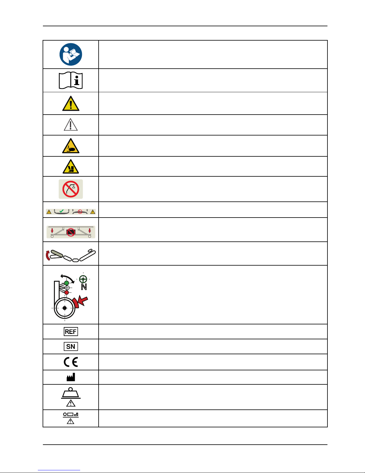
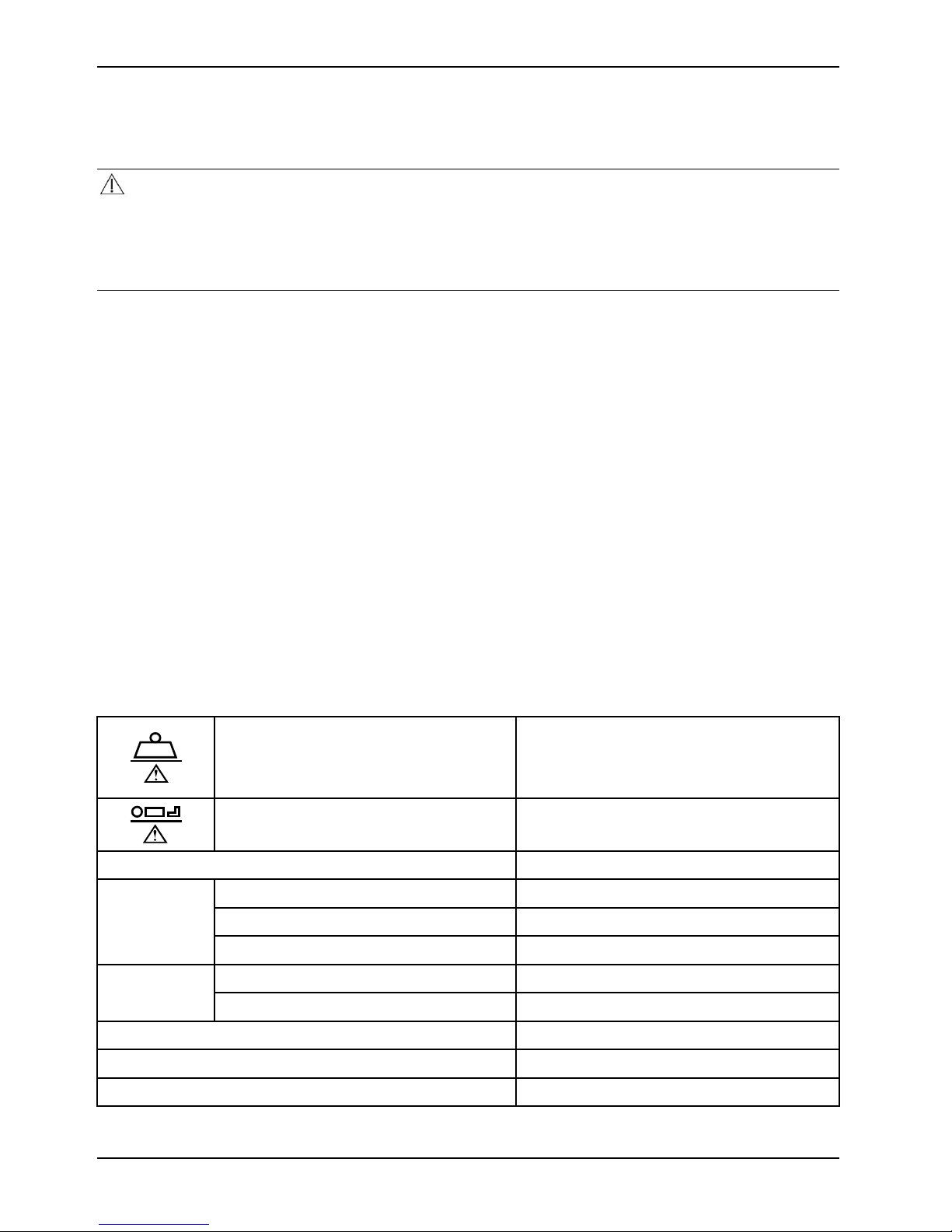
Symbols
Refer to instruction manual/booklet
Operating instructions / Consult instructions for use
General warning
Caution
Warning; crushing of hands
Warning; crushing of feet
Do not insert lift pole
Headboard and footboard orientation
Do not store items under the bed.
Gatch positioning
Caster lock
Catalogue number
Serial number
CE mark
Manufacturer
Safe working load
Maximum patient weight
www.stryker.com SM-7100 REV 01
Page 4
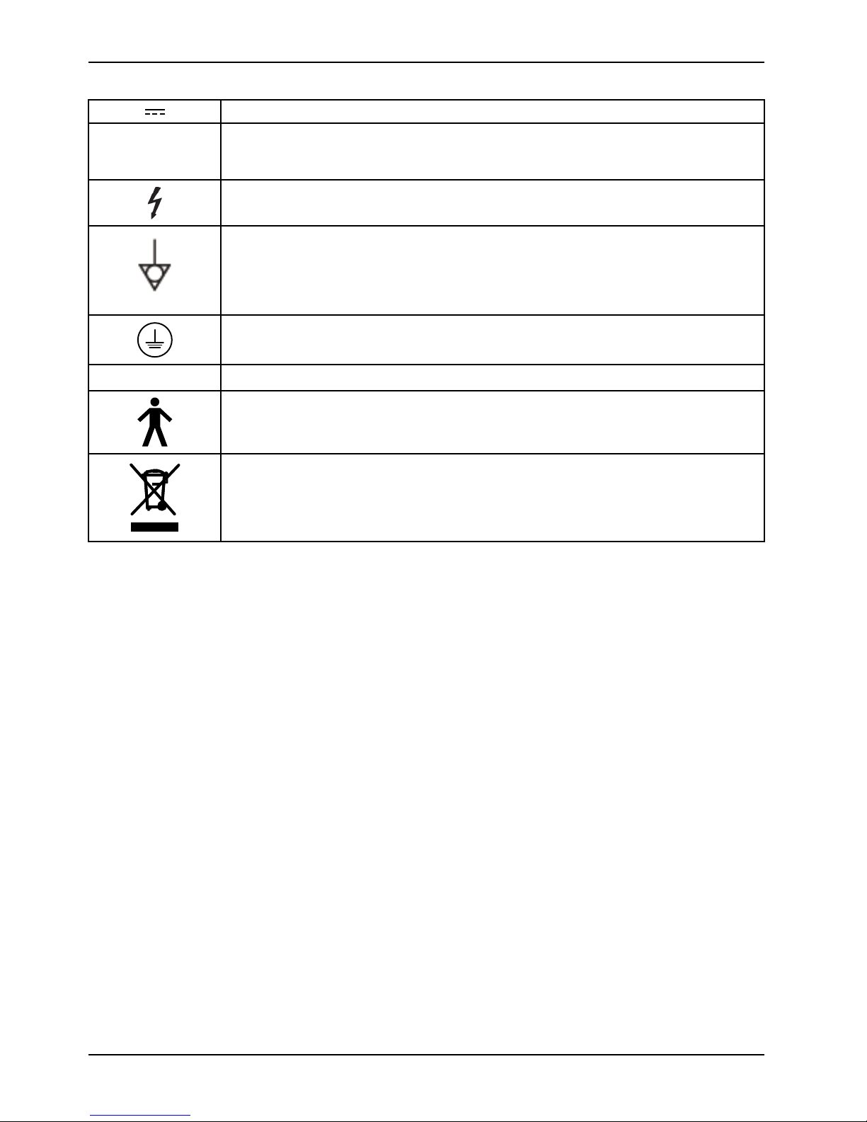
Symbols
~
Direct current
Alternating current
Dangerous voltage
Unit provides terminal for connection of a potential equalization conductor. The potential
equalization conductor provides direct connection between the unit and potential equalization
busbar of the electrical installation.
Protective Earth terminal
IPX4
Protection from liquid splash
Type B applied part
In accordance with European Directive 2012/19/EU on Waste Electrical and Electronic
Equipment (WEEE), this symbol indicates that the product must not be disposed of as
unsorted municipal waste, but should be collected separately. Contact your local distributor
for disposal information. See the maintenance manual for servicing instructions and
recyclable components.
SM-7100 REV 01 www.stryker.com
Page 5

Table of Contents
Warning/Caution/Note Definition .................................................................................................................. 3
Summary of safety precautions....................................................................................................................4
Pinch points ....................................................................................................................................... 5
Introduction.............................................................................................................................................. 6
Expected service life............................................................................................................................6
Warranty ...........................................................................................................................................6
Specifications.....................................................................................................................................6
Product illustration...............................................................................................................................9
Contact information ........................................................................................................................... 10
Serial number location ....................................................................................................................... 10
Cleaning................................................................................................................................................ 11
Preparing the product for cleaning........................................................................................................ 11
Cleaning.......................................................................................................................................... 11
Cleaning the siderails......................................................................................................................... 12
Disinfecting............................................................................................................................................ 13
Preventive maintenance ........................................................................................................................... 14
Quick reference replacement parts............................................................................................................. 16
Troubleshooting ...................................................................................................................................... 45
Service ................................................................................................................................................. 48
Fowler (backrest) actuator replacement................................................................................................. 48
Gatch (legrest) actuator replacement.................................................................................................... 48
Head end lift actuator replacement ....................................................................................................... 49
Foot end lift actuator replacement ........................................................................................................ 50
Non-steer caster replacement.............................................................................................................. 52
Steer (head left) caster replacement..................................................................................................... 53
Head end siderail gas cylinder replacement............................................................................................ 54
Foot end siderail gas cylinder replacement............................................................................................. 55
Brake / steer pedal replacement .......................................................................................................... 56
Lower leg section locking mechanism replacement .................................................................................. 57
Patient control pendant replacement ..................................................................................................... 58
Nurse control pendant replacement ...................................................................................................... 58
Siderail control panel (inside and outside siderail) replacement .................................................................. 59
Control box replacement..................................................................................................................... 59
Battery replacement .......................................................................................................................... 60
Power cord replacement..................................................................................................................... 61
Head end siderail hoop replacement ..................................................................................................... 62
Foot end siderail hoop replacement ...................................................................................................... 63
Brake system ......................................................................................................................................... 64
Base and leg assembly............................................................................................................................. 66
Litter / frame assembly............................................................................................................................. 68
Bumper roller assembly............................................................................................................................ 70
Bed extender assembly ............................................................................................................................ 71
Hi-Lo actuators ....................................................................................................................................... 73
www.stryker.com SM-7100 REV 01 1
Page 6

Table of Contents
Control box and battery ............................................................................................................................ 74
Litter fowler (backrest) assembly................................................................................................................ 75
Litter seat assembly................................................................................................................................. 77
Litter gatch (legrest) assembly................................................................................................................... 78
Fowler (backrest) actuator ........................................................................................................................ 80
Gatch (legrest) actuator ........................................................................................................................... 81
Siderail head end assembly....................................................................................................................... 82
Siderail assembly .................................................................................................................................... 84
Siderail foot end assembly ........................................................................................................................ 85
Siderail release latch assembly.................................................................................................................. 86
Headboard and footboard assembly............................................................................................................ 87
Recycling passports................................................................................................................................. 88
EMC information ..................................................................................................................................... 98
2 SM-7100 REV 01 www.stryker.com
Page 7

Warning/Caution/Note Definition
The words WARNING, CAUTION, and NOTE carry special meanings and should be carefully reviewed.
WARNING
Alerts the reader about a situation which, if not avoided, could result in death or serious injury. It may also describe
potential serious adverse reactions and safety hazards.
CAUTION
Alerts the reader of a potentially hazardous situation which, if not avoided, may result in minor or moderate injury to the
user or patient or damage to the product or other property. This includes special care necessary for the safe and
effective use of the device and the care necessary to avoid damage to a device that may occur as a result of use or
misuse.
Note: Provides special information to make maintenance easier or important instructions clearer.
www.stryker.com SM-7100 REV 01 3
Page 8
Summary of safety precautions
Always read and strictly follow the warnings and cautions listed on this page. Service only by qualified personnel.
WARNING
• Only use the input voltage and frequency as rated on the product.
• Do not clean, service, or perform maintenance while the product is in use.
• Always power off and unplug the power cord before cleaning, servicing, or performing maintenance.
• Always power off the product and unplug the power cord from the wall outlet when large spills occur near the circuit
boards, cables, and motors. Remove the patient from the product, clean up the fluid, and have service personnel
inspect the product. Fluids can cause unpredictable operation and decreased functionality of any electrical product.
Do not return the product to service until it is completely dry and has been thoroughly tested for safe operation.
• Do not spray cleaners directly onto the battery, control boxes, actuators, cables, or other electric equipment.
• Do not use abrasive powder, steel wool, or similar materials that may damage the product surface.
• Do not use Virex
• Do not use acid-based chemicals or flammable chemicals, such as gasoline, diesel, or acetone for cleaning
purposes.
• Do not directly spray or saturate the siderail control panel, patient control pendant, or nurse control pendant with
cleaners.
• Do not use sharp objects to clean the siderail control panel.
• Always make sure to line the hex shaft with the hex in the caster. Test the caster to identify the direction of the
brake. Damage may occur if you install the caster incorrectly.
®
TB for product disinfecting.
CAUTION
• Improper usage of the product can cause injury to the patient or operator. Operate the product only as described in
this manual.
• Do not modify the product or any components of the product. Modifying the product can cause unpredictable
operation resulting in injury to patient or operator. Modifying the product also voids its warranty.
• To minimize the risk of any electromagnetic interference, the product design follows the standard IEC 60601-1-2.
To avoid problems, use the bed in accordance with the EMC/EMI requirements in the EMC section of this
operations manual.
• Portable and mobile RF communications equipment can produce electromagnetic interference with SV1. To prevent
interference caused by portable and mobile RF communications equipment, maintain a minimum distance between
portable and mobile communications equipment and SV1 according to the EMC section of this operations manual.
• Do not steam clean, pressure wash, ultrasonically clean, or immerse any part of the product in water. Exposure to
water may damage the internal electric parts. These methods of cleaning are not recommended and may void this
product’s warranty.
• Always make sure that you wipe each product with clean water and thoroughly dry each product after cleaning.
Some cleaning products are corrosive in nature and may cause damage to the product if you use them improperly.
If you do not properly rinse and dry the product, you may leave a corrosive residue on the surface of the product
that could cause premature corrosion of critical components. Failure to follow these cleaning instructions may void
your warranty.
4 SM-7100 REV 01 www.stryker.com
Page 9
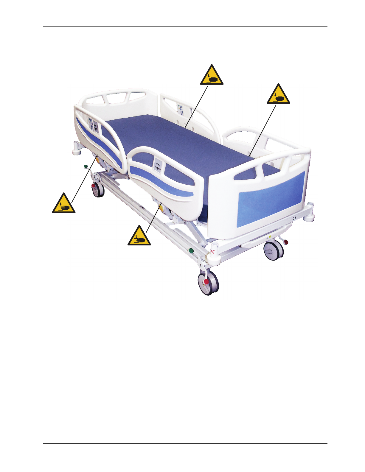
Pinch points
Summary of safety precautions
www.stryker.com SM-7100 REV 01 5
Figure 1: SV1 pinch points
Page 10
Introduction
This manual assists you with the operation or maintenance of your Stryker product. Read this manual before operating
or maintaining this product. Set methods and procedures to educate and train your staff on the safe operation or
maintenance of this product.
CAUTION
• Improper usage of the product can cause injury to the patient or operator. Operate the product only as described in
this manual.
• Do not modify the product or any components of the product. Modifying the product can cause unpredictable
operation resulting in injury to patient or operator. Modifying the product also voids its warranty.
Notes
• This manual is a permanent part of the product and should remain with the product even if the product is sold.
• Stryker continually seeks advancements in product design and quality. This manual contains the most current
product information available at the time of printing. There may be minor discrepancies between your product and
this manual. If you have any questions, contact Stryker Customer Service or Technical Support at + 90 (352) 321
43 00 (pbx).
Expected service life
SV1 has a five year expected service life under normal use conditions and with appropriate periodic maintenance.
The battery has a one year expected service life under normal use conditions.
Warranty
Warranty may vary by country. Contact your local Stryker Medical representative for additional information.
Specifications
Safe working load
Note: Safe working load indicates the sum of
the patient, mattress, and accessory weight
Maximum patient weight 215 kg
Product weight 150 kg
Length 2200 mm (±10 mm)
Overall product
size
Length (with bed extender - option) 2510 mm (±10 mm)
Width
230 kg
990 mm (±10 mm)
Product height
(without mattress)
Under product clearance
Caster size (single and optional dual-casters)
Product angle indicator
6 SM-7100 REV 01 www.stryker.com
Low
High 750 mm (±10 mm)
370 mm (±10 mm)
150 mm
150 mm
0° - 15°
Page 11
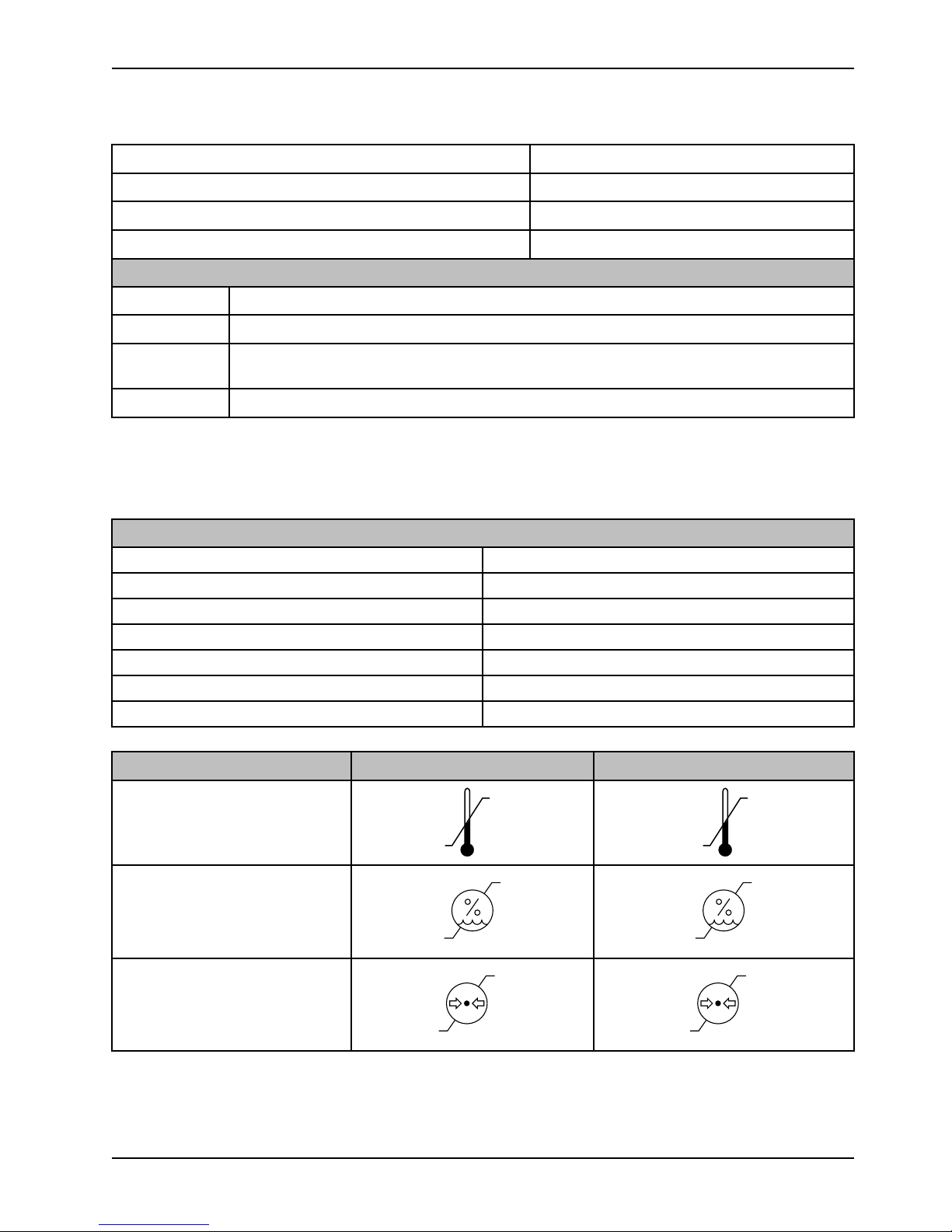
Specifications (Continued)
(38 °C)
(5 °C)
(50 °C)
(-10 °C)
90%
20%
90%
20%
1060 hPa
800 hPa
1060 hPa
800 hPa
Introduction
Backrest angle indicator
Backrest angle
Trendelenburg/Reverse Trendelenburg
Gatch angle
Electrical requirements
Battery
Control box
Electrical
classification
Duty cycle
Class I Equipment: Equipment that protects against electrical shock and does not solely rely on basic insulation, but
which includes an additional safety precaution that is provided for the connection of the equipment to the protective
earth conductor in the fixed wiring of the installation that accessible metal parts cannot become live in the event of a
failure of basic insulation.
Compatible mattresses
7002-2-012 2000 mm x 860 mm x 120 mm
7002-2-014 2000 mm x 860 mm x 140 mm
7002-5-012 2000 mm x 860 mm x 120 mm
7002-2-512 2000 mm x 860 mm x 120 mm
7002-2-514 2000 mm x 860 mm x 140 mm
7002-2-514 2000 mm x 860 mm x 120 mm
7002-5-712 2000 mm x 860 mm x 120 mm
24 VDC, 10 amps, Model BA1812
100-240 VAC, 50 Hz - 60 Hz nominal, 5 amps
Class 1 when product is plugged into mains power
Internally powered when the product is unplugged
2 mins of actuation and 18 mins idle
0° - 90°
0° - 65°
0° - 12°
0° - 30°
Environmental conditions
Temperature
Relative humidity
Atmospheric pressure
www.stryker.com SM-7100 REV 01 7
Operation Storage and transportation
Page 12
Introduction
Specifications (Continued)
Specifications listed are approximate and may vary slightly from product to product or by power supply fluctuations.
Stryker reserves the right to change specifications without notice.
Standards applied
IEC 60601-1:2005+CORR 1 (2006) + CORR 2 (2007)
IEC 60601-1-2:2007
IEC 60601-2-52:2009
IEC 60601-2-54:2009*
*Only applicable when the product is equipped with
the radiolucent backrest option
Medical electrical equipment - Part 1: General requirements
for basic safety and essential performance
Medical electrical equipment - Part 1-2: General
requirements for basic safety and essential performance Collateral standard: Electromagnetic compatibility Requirements and tests
Medical electrical equipment - Part 2-52: Particular
requirements for the basic safety and essential performance
of medical beds
Medical electrical equipment - Part 2-54: Particular
requirements for the basic safety and essential performance
of X-ray equipment for radiography and radioscopy
WARNING
Only use the input voltage and frequency as rated on the product.
CAUTION
• To minimize the risk of any electromagnetic interference, the product design follows the standard IEC 60601-1-2.
To avoid problems, use the bed in accordance with the EMC/EMI requirements in the EMC section of this
operations manual.
• Portable and mobile RF communications equipment can produce electromagnetic interference with SV1. To prevent
interference caused by portable and mobile RF communications equipment, maintain a minimum distance between
portable and mobile communications equipment and SV1 according to the EMC section of this operations manual.
8 SM-7100 REV 01 www.stryker.com
Page 13
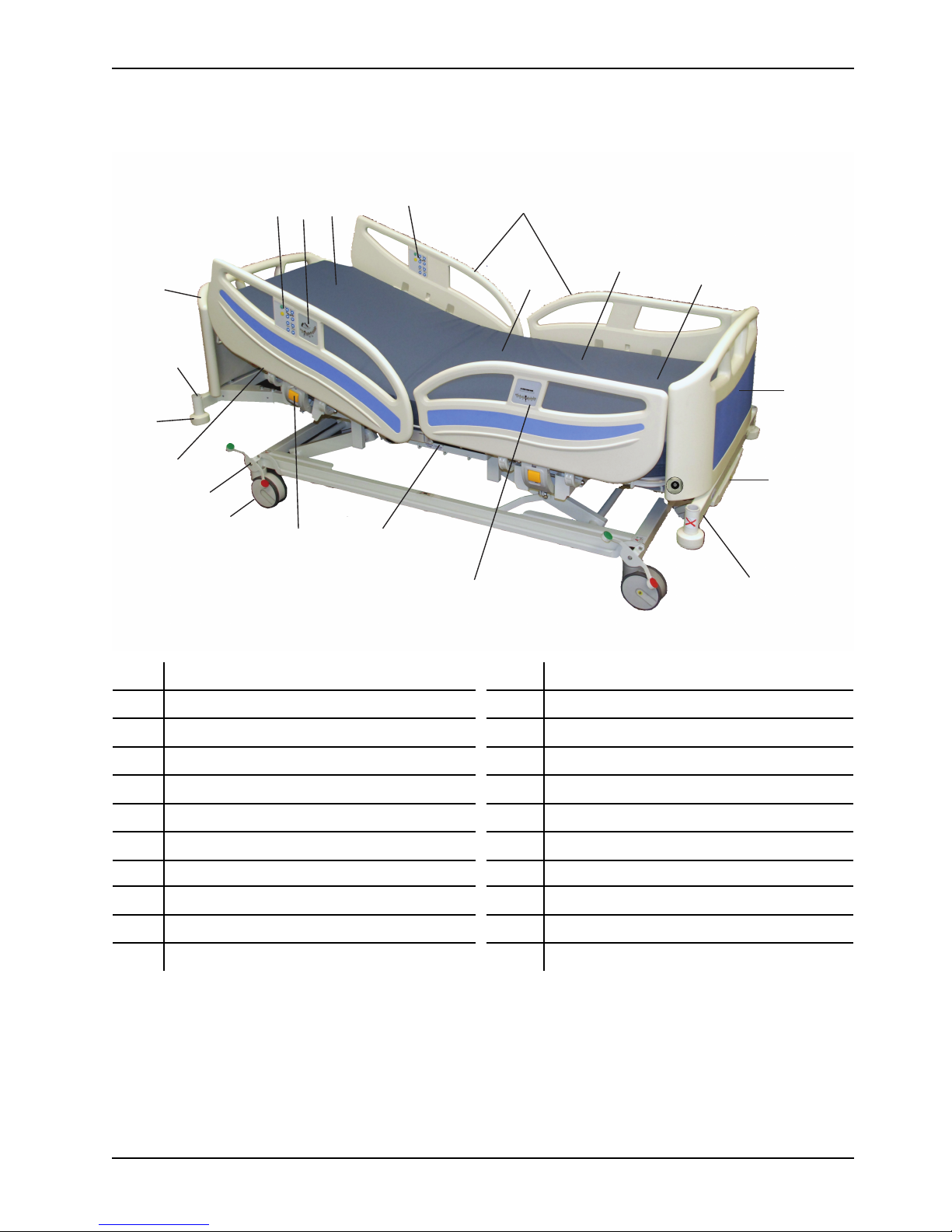
Product illustration
A
B
C
D E
F
G
H
I
J
K
L
M
P
O
R
S
T
Q
N
Introduction
A
B Backrest M
C Backrest indicator N
D
E
F
G
H CPR release S Siderail latch
I
J Footboard
K
Accessory sleeve
Bed angle indicator
Bed extender (option)
Brake/steer pedal
Casters (Dual-wheel casters optional)
Foley hooks
Headboard
L
O Seat section
P Siderails
Q
R
T
Linen tray (option)
Lower leg section
Roller bumper
Siderail control panel (Inside siderail) (option)
Siderail control panel (Outside siderail) (option)
Upper leg section
Nurse control pendant (not shown)
Patient control pendant (option) (not shown)
www.stryker.com SM-7100 REV 01 9
Page 14
Contact information
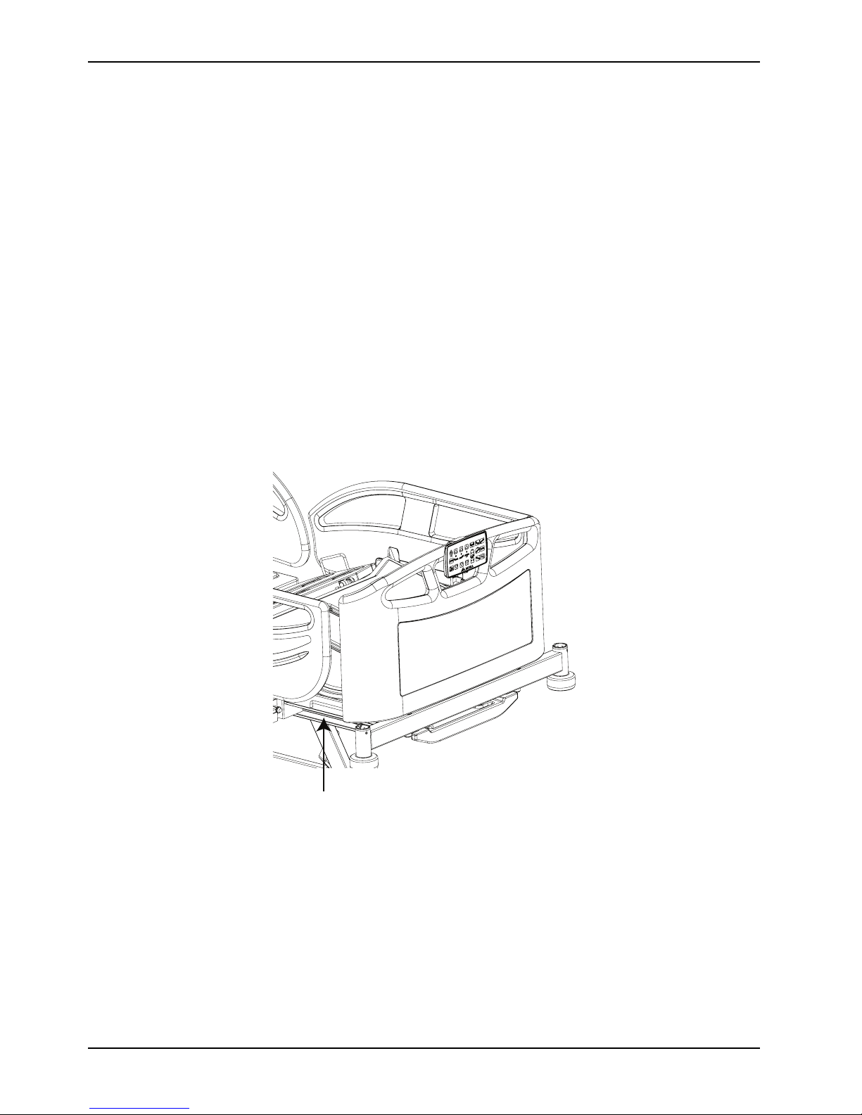
A
Contact your Stryker Customer Service:
Stryker Medical International
Kayseri Serbest Bölge Şubesi
2. Cad. No:17 38070
Kayseri, Turkey
Introduction
E-mail :
Phone : + 90 (352) 321 43 00 (pbx)
Fax: + 90 (352) 321 43 03
Have the serial number (A) of your product available. Include the serial number in all written communication.
infosmi@stryker.com
www.mukametal.com
Serial number location
10 SM-7100 REV 01 www.stryker.com
Page 15
Cleaning
Preparing the product for cleaning
Cleaning and disinfecting are two separate processes. Clean before disinfecting to make sure that the cleaning agent is
effective.
To prepare the product for cleaning:
1. Raise the litter to its highest height.
2. Lock the siderail control panel and patient control pendant functions.
3. Unplug the power cord from the wall outlet.
4. Store the power cord.
5. Apply the brakes.
6. Remove the mattress.
Cleaning
WARNING
• Do not clean, service, or perform maintenance while the product is in use.
• Always power off and unplug the power cord before cleaning, servicing, or performing maintenance.
• Always power off the product and unplug the power cord from the wall outlet when large spills occur near the circuit
boards, cables, and motors. Remove the patient from the product, clean up the fluid, and have service personnel
inspect the product. Fluids can cause unpredictable operation and decreased functionality of any electrical product.
Do not return the product to service until it is completely dry and has been thoroughly tested for safe operation.
• Do not spray cleaners directly onto the battery, control boxes, actuators, cables, or other electric equipment.
• Do not use abrasive powder, steel wool, or similar materials that may damage the product surface.
• Do not use Virex
• Do not use acid-based chemicals or flammable chemicals, such as gasoline, diesel, or acetone for cleaning
purposes.
• Do not directly spray or saturate the siderail control panel, patient control pendant, or nurse control pendant with
cleaners.
®
TB for product disinfecting.
CAUTION
• Do not steam clean, pressure wash, ultrasonically clean, or immerse any part of the product in water. Exposure to
water may damage the internal electric parts. These methods of cleaning are not recommended and may void this
product’s warranty.
• Always make sure that you wipe each product with clean water and thoroughly dry each product after cleaning.
Some cleaning products are corrosive in nature and may cause damage to the product if you use them improperly.
If you do not properly rinse and dry the product, you may leave a corrosive residue on the surface of the product
that could cause premature corrosion of critical components. Failure to follow these cleaning instructions may void
your warranty.
To clean product surfaces:
1. Using a clean, soft, damp cloth, wipe product surfaces with a mild soap and water solution to remove foreign
material.
2. Wipe product surfaces with a clean, dry cloth to remove any excess liquid or cleaning agent.
3. Dry thoroughly.
www.stryker.com SM-7100 REV 01 11
Page 16

Cleaning
Cleaning the siderails
WARNING
• Do not directly spray or saturate the siderail control panel, patient control pendant, or nurse control pendant with
cleaners.
• Do not use sharp objects to clean the siderail control panel.
• Do not use abrasive powder, steel wool, or similar materials that may damage the product surface.
• Do not use Virex
• Do not use acid-based chemicals or flammable chemicals, such as gasoline, diesel, or acetone for cleaning
purposes.
To clean the siderails:
1. Raise the siderail.
2. Latch the siderail.
3. Use a clean, soft, damp cloth to wipe down the siderail and the siderail control panel.
4. Allow the siderail control panel to dry thoroughly.
®
TB for product cleaning.
12 SM-7100 REV 01 www.stryker.com
Page 17

Disinfecting
Suggested disinfectants:
• Quaternary cleaners without glycol ethers (active ingredient - ammonium chloride)
• Phenolic cleaners (active ingredient - o-phenylphenol)
• Chlorinated bleach solution (5.25% - less than 1 part bleach to 100 parts water)
• 70% Isopropyl alcohol
Always follow the disinfectant’s instructions for appropriate contact time and rinsing requirements.
Avoid oversaturation and make sure that the product does not stay wet longer than the chemical manufacturer’s
guidelines for proper disinfecting.
To disinfect the product:
1. Thoroughly clean and dry the product before you apply disinfectants.
2. Apply recommended disinfectant solution by spray or pre-soaked wipes
Note: Make sure that you follow the disinfectant’s instructions for appropriate contact time and rinsing
requirements.
3. To disinfect mechanisms, lift the backrest and leg rest up to the highest height.
4. Wipe product surfaces and mechanisms with a clean, dry cloth to remove any excess liquid or cleaning agent.
5. Allow the product to dry completely before returning to service.
www.stryker.com SM-7100 REV 01 13
Page 18

Preventive maintenance
At a minimum, check all items listed during annual preventive maintenance for all Stryker Medical products. You may
need to perform preventive maintenance checks more frequently based on your level of product usage.
Remove product from service before performing preventive maintenance. Preventive maintenance should only be
performed by trained or certified personnel. See the maintenance manual for servicing and maintenance instructions.
Inspect the following items:
All welds and all fasteners are secure
Tubing or sheet metal for bends or breaks
Casters are free of debris
Casters are secure and swivel
Casters lock securely by depressing the brake pedal
Locking steer caster applies and releases
Steer pedal latches
Backrest operates
Litter up and down operates
Trendelenburg and Reverse Trendelenburg operates
IV pole is intact and operating (optional)
Accessory sleeves are not damaged or cracked
Bed extender extends and locks (option)
Headboard, footboard, and siderail panels for cracks or splits
All covers are not damaged and do not have sharp edges
Radiolucent backrest is clean and not cracked (option)
Cassette holder is clean and not cracked (option)
Underbed light operates
CPR release operates
Siderails move, latch, and stow
All functionality on all control panels
Batteries for replacement
Batteries for corrosion at the terminals, cracking, expanded or bulging at the sides, or can no longer maintain a
full charge
Lower leg section moves, latches, and stows
Pendants for any physical damage
Power cord not worn or frayed
Cables not worn or pinched
All electrical connections tight
All grounds secure to the frame
Ground Impedance Check ( ≤ 0.2 Ohm)
Leakage current: Normal Polarity, No Ground, L2 Active ( ≤ 300 µA)
Leakage current: Normal Polarity, No Ground, No L2 (≤ 600 µA)
Leakage current: Reverse Polarity, No Ground, L2 Active (≤ 300 µA)
Leakage current: Reverse Polarity, no Ground, No L2 (≤ 600 µA)
Enclosure is free from wear, tear, stresses and mechanical damage
High potential test 1500 VAC (trip current not more than 10 mA)
No rust or corrosion of parts
Control boxes are not damaged or cracked
Actuator functionality
Labels for legibility, proper adherence, and integrity
14 SM-7100 REV 01 www.stryker.com
Page 19

Product serial number:
Completed by:
Date:
Preventive maintenance
www.stryker.com SM-7100 REV 01 15
Page 20
Quick reference replacement parts
These parts are currently available for purchase. Call Stryker Customer Service: 1-800-327-0770 for availability and
pricing.
Name Number
Chassis, upper backrest
YM-008-013-LM-BY
Chassis, upper chassis leg rest
Chassis, upper middle
Control unit, siderail
CPR handle
IV pole height adjustment plastics, kit HM-20-127
IV pole bottle holder plastics, kit HM-20-128
Multi junction box (MJB) HM-17-156
Release wire HM-20-206
Kit name Number Kit contents
Number Name
Actuator kit, fowler
(backrest), see
Fowler (backrest)
actuator on page 80
YM-KIT-100006 HM-11-03 10 mm snap ring DIN
HM-12-FTR004 12-FTR004 10 x 53
HM-17-248
YM-007-006-BY
YM-006-003-BY
HM-17-310
HM-17-311
HM-02-13
HM-17-183
471
actuator pin
312887-00 future LB
release backrest
actuator Linak type
Quantity
2
2
1
Actuator kit, gatch
(legrest), see Gatch
(legrest) actuator on
page 81
HM-17-184 0961006-B high/low
actuator snap ring
YM-KIT-100007 HM-02-283 2 mm plastic washer
(10 mm plastic
washer) mould NO
34
HM-11-03 10 mm snap ring DIN
471
HM-12-FTR004 12-FTR004 10 x 53
actuator pin
HM-12-FTR006
HM-17-249
YM-HM-02-285
YM-HM-02-287
12-FTR006 calf pin
J04257 future LB
legrest actuator
Linak type
7 mm PLS washer
(10 mm thick washer
new type)
10*14 mm PLS
washer mould NO 36
1
2
3
1
1
1
2
2
16 SM-7100 REV 01 www.stryker.com
Page 21

Quick reference replacement parts
Kit name Number Kit contents
Number Name
Actuator kit, lift, see
Hi-Lo actuators on
page 73
YM-KIT-100008 HM-11-03 10 mm snap ring DIN
HM-12-112
471
12-112 Ø10 x 39.5
mm stepped pin
Quantity
2
1
Battery replacement
kit, see Control box
and battery on page
74
Brake pedal
replacement kit, see
Brake system on
page 64
HM-12-FTR004 12-FTR004 10 x 53
actuator pin
HM-17-100 J03648 (31410H
+1115004K CB16
Linak high/low
actuator)
HM-17-184 0961006-B high/low
actuator snap ring
YM-KIT-100001 HM-05-043 M5*20 imbus bolt
HM-07-22 M6 iron washer
(small)
HM-08-04
HM-16-03
HM-17-16 BA1812-1300-000
YM-KIT-100037 HM-05-135 6*20 steel bolt
HM-07-22 M6 iron washer
HM-08-05
HM-11-10 11 mm snap ring
HM-11-20
M5 fibered nut
Ø25 clips (UB250C-
N 245X4, cable
connector)
Linak CB6 battery
(small)
M6 fibered nut
(lipper) KMS starlock
push on BV/6706
fastener
Q11 capped snap
ring DT/6673/44A
1
1
1
4
4
4
2
1
1
1
1
1
2
www.stryker.com SM-7100 REV 01 17
HM-12-905
YM-FUTURELBPDL001-BY
YM-HM-02-62 Red brake rubber
YM-HM-02-63
YM-HM-02-71
Transfer laser cut
part bushing (bronz)
Future LB pedal
white
MKA062 DMR062
Green brake rubber
MKA063 DMR063
12 thick PLS washer
DMR071
1
1
1
1
1
Page 22

Quick reference replacement parts
Kit name Number Kit contents
Number Name
Caster kit, dual
wheel non steer (150
mm), see Brake
system on page 64
YM-KIT-100004 HM-01-26 2946UAP150R36-
HM-05-106 M6*16 imbus bolt 2
HM-09-04 6 mm serrated
HM-11-10 11 mm snap ring
HM-11-20
32S30 D RAL 9002
4XM6 TENTE 150
mm double lockable
caster (Stryker)
washer (ring) DIN
6798
(lipper) KMS starlock
push on BV/6706
fastener
Q11 capped snap
ring DT/6673/44A
Quantity
1
2
2
2
Caster kit, dual
wheel steer (150
mm), see Brake
system on page 64
YM-HM-02-71
YM-HM-02-299
YM-KIT-100003 HM-01-25
HM-05-106 M6*16 imbus bolt 2
HM-09-04 6 mm serrated
HM-11-10 11 mm snap ring
HM-11-20
YM-HM-02-71
YM-HM-02-299
12 thick PLS washer
DMR071
50*50 caster profile
cap PLS (lower
chasis PLS) 51
mould
2944USP150R3632S30 D RAL 9002
4XM6 TENTE 150
mm double
directional caster
(Stryker)
washer (ring) DIN
6798
(lipper) KMS starlock
push on BV/6706
fastener
Q11 capped snap
ring DT/6673/44A
12 thick PLS washer
DMR071
50*50 caster profile
cap PLS (lower
chasis PLS) 51
mould
2
1
1
2
2
2
2
1
18 SM-7100 REV 01 www.stryker.com
Page 23

Quick reference replacement parts
Kit name Number Kit contents
Number Name
Caster kit, single
wheel direction lock,
see Brake system on
page 64
YM-KIT-100011 HM-01-55
HM-05-106 M6*16 imbus bolt 2
HM-09-04 6 mm serrated
HM-11-10 11 mm snap ring
HM-11-20
2044XSX150R3632S30 150 mm
directional single
integral antistatic
caster
washer (ring) DIN
6798
(lipper) KMS starlock
push on BV/6706
fastener
Q11 capped snap
ring DT/6673/44A
Quantity
1
2
2
2
Caster kit, single
wheel standard, see
Brake system on
page 64
YM-HM-02-71
YM-HM-02-299
YM-KIT-100012 HM-01-54 2046UAP150R36-
HM-05-106 M6*16 imbus bolt 2
HM-09-04 6 mm serrated
HM-11-10 11 mm snap ring
HM-11-20
YM-HM-02-71
YM-HM-02-299
12 thick PLS washer
DMR071
50*50 caster profile
cap PLS (lower
chasis PLS) 51
mould
32S30 150 mm
lockable single
integral caster
washer (ring) DIN
6798
(lipper) KMS starlock
push on BV/6706
fastener
Q11 capped snap
ring DT/6673/44A
12 thick PLS washer
DMR071
50*50 caster profile
cap PLS (lower
chasis PLS) 51
mould
2
1
1
2
2
2
2
1
www.stryker.com SM-7100 REV 01 19
Page 24

Quick reference replacement parts
Kit name Number Kit contents
Number Name
Control box
replacement kit, see
Control box and
battery on page 74
Footboard kit with
logo, dark blue, see
Headboard and
footboard assembly
on page 87
YM-KIT-100002 HM-05-010 M6*50 steel bolt
HM-07-01 M6 metal standard
HM-08-05
HM-17-373
YM-KIT-100033
YM-FTRBASLIK-MN1
HM-20-850
washer (large) 1/4
washer
M6 fibered nut
QFUTURE LB CB6
control box new type
system (CB6S674
+X4409) CB6663-00
100-240 volt
Future polypropylene
bed head and foot
assembly
Dark blue (Stryker)
foot end bed head
color sticker with
Stryker logo
Quantity
1
2
1
1
1
1
Headboard kit, dark
blue, see Headboard
and footboard
assembly on page
87
Headboard kit, dark
wood, see
Headboard and
footboard assembly
on page 87
Headboard kit, light
wood, see
Headboard and
footboard assembly
on page 87
Headboard kit, wood,
see Headboard and
footboard assembly
on page 87
YM-KIT-100005-B
YM-KIT-100005-D
YM-KIT-100005-L
YM-KIT-100005-W
YM-FTRBASLIK-MN1
HM-20-851
YM-FTRBASLIK-MN1
HM-20-763
YM-FTRBASLIK-MN1
HM-20-753
YM-FTRBASLIK-MN1
HM-20-758
Future polypropylene
head and foot
assembly
Dark blue (Stryker)
head color sticker
Future polypropylene
head and foot
assembly
08 dark wood future
bed head color
Future polypropylene
head and foot
assembly
06 light wood future
bed head color
Future polypropylene
head and foot
assembly
07 wood color future
bed head color
1
1
1
1
1
1
1
1
20 SM-7100 REV 01 www.stryker.com
Page 25

Quick reference replacement parts
Kit name Number Kit contents
Number Name
Label kit, dark blue YM-KIT-100032 HM-20-850
Dark blue (Stryker)
foot end bed head
color sticker with
Stryker logo
Quantity
1
HM-20-851
HM-20-852
HM-20-853
HM-20-854
HM-20-855
HM-22-1780 3M primer 94
Label kit, dark wood YM-KIT-100036 HM-20-759
HM-20-760
HM-20-761
Dark blue (Stryker)
head color sticker
Dark blue (Stryker)
upper right siderail
color sticker
Dark blue (Stryker)
upper left siderail
color sticker
Dark blue (Stryker)
lower right siderail
color sticker
Dark blue (Stryker)
lower left siderail
color sticker
handkerchief
08 dark wood future
siderail color, back
right
08 dark wood future
siderail color, back
left
08 dark wood future
siderail color, foot
right
1
1
1
1
1
6
1
1
1
HM-20-762
HM-20-763
HM-22-1780 3M primer 94
www.stryker.com SM-7100 REV 01 21
08 dark wood future
siderail color, foot
left
08 dark wood future
bed head color
handkerchief
1
2
6
Page 26

Quick reference replacement parts
Kit name Number Kit contents
Number Name
Label kit, light wood YM-KIT-100034 HM-20-749
06 light wood future
siderail color, back
right
Quantity
1
HM-20-750
HM-20-751
HM-20-752
HM-20-753
HM-22-1780 3M primer 94
Label kit, wood YM-KIT-100035 HM-20-754
HM-20-755
HM-20-756
06 light wood future
siderail color, back
left
06 light wood future
siderail color, foot
right
06 light wood future
siderail color, foot
left
06 light wood future
bed head color
handkerchief
07 wood color future
siderail color, back
right
07 wood color future
siderail color, back
left
07 wood color future
siderail color, foot
right
1
1
1
2
6
1
1
1
Nurse control
pendant kit
HM-20-757
HM-20-758
HM-22-1780 3M primer 94
YM-KIT-100017 HM-16-03
HM-17-103 0964541 Linak
HM-17-175
HM-17-186
07 wood color future
siderail color, foot
left
07 wood color future
bed head color
handkerchief
Ø25 clips (UB250C-
N 245X4, 6 cable
connector)
supervisor spiral
cable
AC0062-00_SV1/CL
Stryker logo nurse
control unit
(supervisor)
00911045 ACO snap
ring
1
2
6
5
1
1
1
22 SM-7100 REV 01 www.stryker.com
Page 27

Quick reference replacement parts
Kit name Number Kit contents
Number Name
Power cord
replacement kit, type
B
YM-KIT-100019 HM-16-03
Ø25 clips (UB250CN 245X4, 6 cable
connector)
Quantity
5
Power cord
replacement kit, type
D
Power cord
replacement kit, type
E-F
Power cord
replacement kit, type
G
Power cord
replacement kit, type
I (Argentina)
HM-17-225 912151-B black
YM-KIT-100020 HM-16-03
HM-17-011 D type energy cable
YM-KIT-100021 HM-16-03
HM-17-104 0015832-A LB and
YM-KIT-100022 HM-16-03
HM-17-013
YM-KIT-100023 HM-16-03
energy cable
(Stryker) B type cable
Ø25 clips (UB250CN 245X4, 6 cable
connector)
(SML912420-A)
Ø25 clips (UB250CN 245X4, 6 cable
connector)
CL E/F type energy
cable
Ø25 clips (UB250CN 245X4, 6 cable
connector)
G type energy cable
(SML912416-B)
Ø25 clips (UB250CN 245X4, 6 cable
connector)
1
5
1
5
1
5
1
5
Power cord
replacement kit, type
I (AUS/NZ)
Power cord
replacement kit, type
J
Power cord
replacement kit, type
K
HM-17-226 0015972-A Argentina
YM-KIT-100024 HM-16-03
HM-17-012 I type energy cable
YM-KIT-100025 HM-16-03
HM-17-015 J type energy cable
YM-KIT-100026 HM-16-03
HM-17-010 K type energy cable
energy cable Linak I
type cable
Ø25 clips (UB250CN 245X4, 6 cable
connector)
(SML912417-A)
Ø25 clips (UB250CN 245X4, 6 cable
connector)
(SML912441-A)
Ø25 clips (UB250CN 245X4, 6 cable
connector)
(SML912419-A)
1
5
1
5
1
5
1
www.stryker.com SM-7100 REV 01 23
Page 28

Quick reference replacement parts
Kit name Number Kit contents
Number Name
Power cord
replacement kit, type
L
YM-KIT-100027 HM-16-03
Ø25 clips (UB250CN 245X4, 6 cable
connector)
Quantity
5
Power cord
replacement kit, type
M
Power cord
replacement kit, type
N
Roller bumper
replacement kit, see
Bumper roller
assembly on page
70
Backrest siderail gas
cylinder kit, see
Siderail assembly on
page 84
HM-17-227
YM-KIT-100028 HM-16-03
HM-17-014 M type energy cable
YM-KIT-100029 HM-16-03
HM-17-228 0015973-A Brazil
YM-KIT-100009 HM-02-354 Future bumper
HM-11-26
HM-12-FTR001
YM-KIT-100010 HM-11-18
HM-12-146 12-146 8 x 31 mm
0015971-A Chile
type energy cable
Linak L type cable
Ø25 clips (UB250CN 245X4, 6 cable
connector)
(SML912418-A)
Ø25 clips (UB250CN 245X4, 6 cable
connector)
energy cable Linak N
type cable
5 mm C shape snap
ring DIN 6799
12-FT001 future
bumper pin
Q8 capped snap ring
(DT/6671/43A)
side rail pin
1
5
1
5
1
1
1
1
2
1
HM-18-27 Future side rail shock
absorber 640015004
HM-05-018
YM-HM-02-418 Future side rail shock
HM-07-03 M8 iron washer 2
HM-08-06
HM-20-557
24 SM-7100 REV 01 www.stryker.com
M8*90 half thread
steel bolt
absorber PLS
M8 fibered nut
Ø15 clips
1
1
2
1
1
Page 29

Quick reference replacement parts
Kit name Number Kit contents
Number Name
Siderail kit, foot end
left, dark blue, see
Siderail foot end
assembly on page
85
YM-KIT-100013-B YM-02-142-MN
HM-22-1780 3M primer 94
HM-12-FTR005 12-FTR005 shock
Left foot siderail
assembly
handkerchief
absorber connection
pin
Quantity
1
1
1
Siderail kit, foot end
left, dark wood, see
Siderail foot end
assembly on page
85
HM-02-283 2 mm plastic washer
HM-11-05
HM-11-19
HM-12-144 12-144 10 x 128 mm
HM-12-145 12-145 10 x 305 mm
HM-20-855
YM-KIT-100013-D YM-02-142-MN
HM-22-1780 3M primer 94
HM-12-FTR005 12-FTR005 shock
(10 mm plastic
washer) mould NO
34
6 mm C shape snap
ring DIN 6799
Q10 capped snap
ring (DT/6668/44A)
siderail pin
siderail pin
Dark blue (Stryker)
lower left siderail
color sticker
Left foot siderail
assembly
handkerchief
absorber connection
pin
6
1
4
1
1
1
1
1
1
www.stryker.com SM-7100 REV 01 25
HM-02-283 2 mm plastic washer
(10 mm plastic
washer) mould NO
34
HM-11-05
HM-11-19
HM-12-144 12-144 10 x 128 mm
HM-12-145 12-145 10 x 305 mm
HM-20-762
6 mm C shape snap
ring DIN 6799
Q10 capped snap
ring (DT/6668/44A)
siderail pin
siderail pin
08 dark wood future
siderail color foot left
6
1
4
1
1
1
Page 30

Quick reference replacement parts
Kit name Number Kit contents
Number Name
Siderail kit, foot end
left, light wood, see
Siderail foot end
assembly on page
85
YM-KIT-100013-L YM-02-142-MN
HM-22-1780 3M primer 94
HM-12-FTR005 12-FTR005 shock
Left foot siderail
assembly
handkerchief
absorber connection
pin
Quantity
1
1
1
Siderail kit, foot end
left, wood, see
Siderail foot end
assembly on page
85
HM-02-283 2 mm plastic washer
HM-11-05
HM-11-19
HM-12-144 12-144 10 x 128 mm
HM-12-145 12-145 10 x 305 mm
HM-20-752
YM-KIT-100013-W YM-02-142-MN
HM-22-1780 3M primer 94
HM-12-FTR005 12-FTR005 shock
(10 mm plastic
washer) mould NO
34
6 mm C shape snap
ring DIN 6799
Q10 capped snap
ring (DT/6668/44A)
siderail pin
siderail pin
06 light wood future
siderail color foot left
Left foot siderail
assembly
handkerchief
absorber connection
pin
6
1
4
1
1
1
1
1
1
26 SM-7100 REV 01 www.stryker.com
HM-02-283 2 mm plastic washer
(10 mm plastic
washer) mould NO
34
HM-11-05
HM-11-19
HM-12-144 12-144 10 x 128 mm
HM-12-145 12-145 10 x 305 mm
HM-20-757
6 mm C shape snap
ring DIN 6799
Q10 capped snap
ring (DT/6668/44A)
siderail pin
siderail pin
07 wood color future
siderail color foot left
6
1
4
1
1
1
Page 31

Quick reference replacement parts
Kit name Number Kit contents
Number Name
Siderail kit, foot end
right, dark blue, see
Siderail foot end
assembly on page
85
YM-KIT-100014-B YM-02-144-MN
HM-22-1780 3M primer 94
HM-12-FTR005 12-FTR005 shock
Right foot siderail
assembly
handkerchief
absorber connection
pin
Quantity
1
1
1
Siderail kit, foot end
right, dark wood, see
Siderail foot end
assembly on page
85
HM-02-283 2 mm plastic washer
HM-11-05
HM-11-19
HM-12-144 12-144 10 x 128 mm
HM-12-145 12-145 10 x 305 mm
HM-20-854
YM-KIT-100014-D YM-02-144-MN
HM-22-1780 3M primer 94
HM-12-FTR005 12-FTR005 shock
(10 mm plastic
washer) mould NO
34
6 mm C shape snap
ring DIN 6799
Q10 capped snap
ring (DT/6668/44A)
siderail pin
siderail pin
Dark blue (Stryker)
lower right siderail
color sticker
Right foot siderail
assembly
handkerchief
absorber connection
pin
6
1
4
1
1
1
1
1
1
www.stryker.com SM-7100 REV 01 27
HM-02-283 2 mm plastic washer
(10 mm plastic
washer) mould NO
34
HM-11-05
HM-11-19
HM-12-144 12-144 10 x 128 mm
HM-12-145 12-145 10 x 305 mm
HM-20-761
6 mm C shape snap
ring DIN 6799
Q10 capped snap
ring (DT/6668/44A)
siderail pin
siderail pin
08 dark wood future
siderail color foot
right
6
1
4
1
1
1
Page 32

Quick reference replacement parts
Kit name Number Kit contents
Number Name
Siderail kit, foot end
right, light wood, see
Siderail foot end
assembly on page
85
YM-KIT-100014-L YM-02-144-MN
HM-22-1780 3M primer 94
HM-12-FTR005 12-FTR005 shock
Right foot siderail
assembly
handkerchief
absorber connection
pin
Quantity
1
1
1
Siderail kit, foot end
right, wood, see
Siderail foot end
assembly on page
85
HM-02-283 2 mm plastic washer
HM-11-05
HM-11-19
HM-12-144 12-144 10 x 128 mm
HM-12-145 12-145 10 x 305 mm
HM-20-751
YM-KIT-100014-W YM-02-144-MN
HM-22-1780 3M primer 94
HM-12-FTR005 12-FTR005 shock
(10 mm plastic
washer) mould NO
34
6 mm C shape snap
ring DIN 6799
Q10 capped snap
ring (DT/6668/44A)
siderail pin
siderail pin
06 light wood future
siderail color foot
right
Right foot siderail
assembly
handkerchief
absorber connection
pin
6
1
4
1
1
1
1
1
1
28 SM-7100 REV 01 www.stryker.com
HM-02-283 2 mm plastic washer
(10 mm plastic
washer) mould NO
34
HM-11-05
HM-11-19
HM-12-144 12-144 10 x 128 mm
HM-12-145 12-145 10 x 305 mm
HM-20-756
6 mm C shape snap
ring DIN 6799
Q10 capped snap
ring (DT/6668/44A)
siderail pin
siderail pin
07 wood color future
siderail color foot
right
6
1
4
1
1
1
Page 33

Quick reference replacement parts
Kit name Number Kit contents
Number Name
Siderail kit, head end
left, dark blue, see
Siderail head end
assembly on page
82
YM-KIT-100015-B YM-02-141-MN1
HM-22-1780 3M primer 94
HM-02-283 2 mm plastic washer
HM-11-19
Back left siderail
assembly with unit
handkerchief
(10 mm plastic
washer) mould NO
34
Q10 capped snap
ring (DT/6668/44A)
Quantity
1
1
4
4
HM-12-144 12-144 10 x 128 mm
siderail pin
HM-12-145 12-145 10 x 305 mm
siderail pin
YM-HM-02-418 Future siderail shock
absorber PLS
HM-05-018
HM-20-557
HM-07-03 M8 iron washer 2
HM-08-06
HM-20-853
M8*90 half thread
steel bolt
Ø15 clips
M8 fibered nut
Dark blue (Stryker)
upper left siderail
color sticker
1
1
2
1
5
1
1
www.stryker.com SM-7100 REV 01 29
Page 34

Quick reference replacement parts
Kit name Number Kit contents
Number Name
Siderail kit, head end
left, dark wood, see
Siderail head end
assembly on page
82
YM-KIT-100015-D YM-02-141-MN1
HM-22-1780 3M primer 94
HM-02-283 2 mm plastic washer
HM-11-19
Back left siderail
assembly with unit
handkerchief
(10 mm plastic
washer) mould NO
34
Q10 capped snap
ring (DT/6668/44A)
Quantity
1
1
4
4
HM-12-144 12-144 10 x 128 mm
siderail pin
HM-12-145 12-145 10 x 305 mm
siderail pin
YM-HM-02-418 Future siderail shock
absorber PLS
HM-05-018
HM-20-557
HM-07-03 M8 iron washer 2
HM-08-06
HM-20-760
M8*90 half thread
steel bolt
Ø15 clips
M8 fibered nut
08 dark wood future
siderail color back
left
1
1
2
1
5
1
1
30 SM-7100 REV 01 www.stryker.com
Page 35

Quick reference replacement parts
Kit name Number Kit contents
Number Name
Siderail kit, head end
left, light wood, see
Siderail head end
assembly on page
82
YM-KIT-100015-L YM-02-141-MN1
HM-22-1780 3M primer 94
HM-02-283 2 mm plastic washer
HM-11-19
Back left siderail
assembly with unit
handkerchief
(10 mm plastic
washer) mould NO
34
Q10 capped snap
ring (DT/6668/44A)
Quantity
1
1
4
4
HM-12-144 12-144 10 x 128 mm
siderail pin
HM-12-145 12-145 10 x 305 mm
siderail pin
YM-HM-02-418 Future siderail shock
absorber PLS
HM-05-018
HM-20-557
HM-07-03 M8 iron washer 2
HM-08-06
HM-20-750
M8*90 half thread
steel bolt
Ø15 clips
M8 fibered nut
06 light wood future
siderail color back
left
1
1
2
1
5
1
1
www.stryker.com SM-7100 REV 01 31
Page 36

Quick reference replacement parts
Kit name Number Kit contents
Number Name
Siderail kit, head end
left, wood, see
Siderail head end
assembly on page
82
YM-KIT-100015-W YM-02-141-MN1
HM-22-1780 3M primer 94
HM-02-283 2 mm plastic washer
HM-11-19
Back left siderail
assembly with unit
handkerchief
(10 mm plastic
washer) mould NO
34
Q10 capped snap
ring (DT/6668/44A)
Quantity
1
1
4
4
HM-12-144 12-144 10 x 128 mm
siderail pin
HM-12-145 12-145 10 x 305 mm
siderail pin
YM-HM-02-418 Future siderail shock
absorber PLS
HM-05-018
HM-20-557
HM-07-03 M8 iron washer 2
HM-08-06
HM-20-755
M8*90 half thread
steel bolt
Ø15 clips
M8 fibered nut
07 wood color future
siderail color back
left
1
1
2
1
5
1
1
32 SM-7100 REV 01 www.stryker.com
Page 37

Quick reference replacement parts
Kit name Number Kit contents
Number Name
Siderail kit, head end
right, dark blue, see
Siderail head end
assembly on page
82
YM-KIT-100016-B YM-02-143-MN1 Back right siderail
HM-22-1780 3M primer 94
HM-02-283 2 mm plastic washer
HM-11-19
assembly with unit
handkerchief
(10 mm plastic
washer) mould NO
34
Q10 capped snap
ring (DT/6668/44A)
Quantity
1
1
4
4
HM-12-144 12-144 10 x 128 mm
siderail pin
HM-12-145 12-145 10 x 305 mm
siderail pin
YM-HM-02-418 Future siderail shock
absorber PLS
HM-05-018
HM-20-557
HM-07-03 M8 iron washer 2
HM-08-06
HM-20-852
M8*90 half thread
steel bolt
Ø15 clips
M8 fibered nut
Dark blue (Stryker)
upper right siderail
color sticker
1
1
2
1
5
1
1
www.stryker.com SM-7100 REV 01 33
Page 38

Quick reference replacement parts
Kit name Number Kit contents
Number Name
Siderail kit, head end
right, dark wood, see
Siderail head end
assembly on page
82
YM-KIT-100016-D YM-02-143-MN1 Back right siderail
HM-22-1780 3M primer 94
HM-02-283 2 mm plastic washer
HM-11-19
assembly with unit
handkerchief
(10 mm plastic
washer) mould NO
34
Q10 capped snap
ring (DT/6668/44A)
Quantity
1
1
4
4
HM-12-144 12-144 10 x 128 mm
siderail pin
HM-12-145 12-145 10 x 305 mm
siderail pin
YM-HM-02-418 Future siderail shock
absorber PLS
HM-05-018
HM-20-557
HM-07-03 M8 iron washer 2
HM-08-06
HM-20-759
M8*90 half thread
steel bolt
Ø15 clips
M8 fibered nut
08 dark wood future
siderail color back
right
1
1
2
1
5
1
1
34 SM-7100 REV 01 www.stryker.com
Page 39

Quick reference replacement parts
Kit name Number Kit contents
Number Name
Siderail kit, head end
right, light wood, see
Siderail head end
assembly on page
82
YM-KIT-100016-L YM-02-143-MN1 Back right siderail
HM-22-1780 3M primer 94
HM-02-283 2 mm plastic washer
HM-11-19
assembly with unit
handkerchief
(10 mm plastic
washer) mould NO
34
Q10 capped snap
ring (DT/6668/44A)
Quantity
1
1
4
4
HM-12-144 12-144 10 x 128 mm
siderail pin
HM-12-145 12-145 10 x 305 mm
siderail pin
YM-HM-02-418 Future siderail shock
absorber PLS
HM-05-018
HM-20-557
HM-07-03 M8 iron washer 2
HM-08-06
HM-20-749
M8*90 half thread
steel bolt
Ø15 clips
M8 fibered nut
06 light wood future
siderail color back
right
1
1
2
1
5
1
1
www.stryker.com SM-7100 REV 01 35
Page 40

Quick reference replacement parts
Kit name Number Kit contents
Number Name
Siderail kit, head end
right, wood, see
Siderail head end
assembly on page
82
YM-KIT-100016-W YM-02-143-MN1 Back right siderail
HM-22-1780 3M primer 94
HM-02-283 2 mm plastic washer
HM-11-19
assembly with unit
handkerchief
(10 mm plastic
washer) mould NO
34
Q10 capped snap
ring (DT/6668/44A)
Quantity
1
1
4
4
HM-12-144 12-144 10 x 128 mm
siderail pin
HM-12-145 12-145 10 x 305 mm
siderail pin
YM-HM-02-418 Future siderail shock
absorber PLS
HM-05-018
HM-20-557
HM-07-03 M8 iron washer 2
HM-08-06
HM-20-754
M8*90 half thread
steel bolt
Ø15 clips
M8 fibered nut
07 wood color future
siderail color back
right
1
1
2
1
5
1
1
36 SM-7100 REV 01 www.stryker.com
Page 41

Quick reference replacement parts
Kit name Number Kit contents
Number Name
Siderail kit, head end
left W/O patient
control pendant, dark
blue, see Siderail
head end assembly
on page 82
YM-KIT-100030-B YM-02-141-MN
HM-22-1780 3M primer 94
HM-02-283 2 mm plastic washer
HM-11-19
Back left siderail
assembly
handkerchief
(10 mm plastic
washer) mould NO
34
Q10 capped snap
ring (DT/6668/44A)
Quantity
1
1
4
4
HM-12-144 12-144 10 x 128 mm
siderail pin
HM-12-145 12-145 10 x 305 mm
siderail pin
YM-HM-02-418 Future siderail shock
absorber PLS
HM-05-018
HM-07-03 M8 iron washer 2
HM-08-06
HM-20-853
M8*90 half thread
steel bolt
M8 fibered nut
Dark blue (Stryker)
upper left siderail
color sticker
1
1
2
1
1
1
www.stryker.com SM-7100 REV 01 37
Page 42
Quick reference replacement parts
Kit name Number Kit contents
Number Name
Siderail kit, head end
left W/O patient
control pendant, dark
wood, see Siderail
head end assembly
on page 82
YM-KIT-100030-D YM-02-141-MN
HM-22-1780 3M primer 94
HM-02-283 2 mm plastic washer
HM-11-19
Back left siderail
assembly
handkerchief
(10 mm plastic
washer) mould NO
34
Q10 capped snap
ring (DT/6668/44A)
Quantity
1
1
4
4
HM-12-144 12-144 10 x 128 mm
siderail pin
HM-12-145 12-145 10 x 305 mm
siderail pin
YM-HM-02-418 Future siderail shock
absorber PLS
HM-05-018
HM-07-03 M8 iron washer 2
HM-08-06
HM-20-760
M8*90 half thread
steel bolt
M8 fibered nut
08 dark wood future
siderail color back
left
1
1
2
1
1
1
38 SM-7100 REV 01 www.stryker.com
Page 43

Quick reference replacement parts
Kit name Number Kit contents
Number Name
Siderail kit, head end
left W/O patient
control pendant, light
wood, see Siderail
head end assembly
on page 82
YM-KIT-100030-L YM-02-141-MN
HM-22-1780 3M primer 94
HM-02-283 2 mm plastic washer
HM-11-19
Back left siderail
assembly
handkerchief
(10 mm plastic
washer) mould NO
34
Q10 capped snap
ring (DT/6668/44A)
Quantity
1
1
4
4
HM-12-144 12-144 10 x 128 mm
siderail pin
HM-12-145 12-145 10 x 305 mm
siderail pin
YM-HM-02-418 Future siderail shock
absorber PLS
HM-05-018
HM-07-03 M8 iron washer 2
HM-08-06
HM-20-750
M8*90 half thread
steel bolt
M8 fibered nut
06 light wood future
siderail color back
left
1
1
2
1
1
1
www.stryker.com SM-7100 REV 01 39
Page 44

Quick reference replacement parts
Kit name Number Kit contents
Number Name
Siderail kit, head end
left W/O patient
control pendant,
wood, see Siderail
head end assembly
on page 82
YM-KIT-100030-W YM-02-141-MN
HM-22-1780 3M primer 94
HM-02-283 2 mm plastic washer
HM-11-19
Back left siderail
assembly
handkerchief
(10 mm plastic
washer) mould NO
34
Q10 capped snap
ring (DT/6668/44A)
Quantity
1
1
4
4
HM-12-144 12-144 10 x 128 mm
siderail pin
HM-12-145 12-145 10 x 305 mm
siderail pin
YM-HM-02-418 Future siderail shock
absorber PLS
HM-05-018
HM-07-03 M8 iron washer 2
HM-08-06
HM-20-755
M8*90 half thread
steel bolt
M8 fibered nut
07 wood color future
siderail color back
left
1
1
2
1
1
1
40 SM-7100 REV 01 www.stryker.com
Page 45

Quick reference replacement parts
Kit name Number Kit contents
Number Name
Siderail kit, head end
right W/O patient
control pendant, dark
blue, see Siderail
head end assembly
on page 82
YM-KIT-100031-B YM-02-143-MN Right back siderail
HM-22-1780 3M primer 94
HM-02-283 2 mm plastic washer
HM-11-19
assembly
handkerchief
(10 mm plastic
washer) mould NO
34
Q10 capped snap
ring (DT/6668/44A)
Quantity
1
1
4
4
HM-12-144 12-144 10 x 128 mm
siderail pin
HM-12-145 12-145 10 x 305 mm
siderail pin
YM-HM-02-418 Future siderail shock
absorber PLS
HM-05-018
HM-07-03 M8 iron washer 2
HM-08-06
HM-20-852
M8*90 half thread
steel bolt
M8 fibered nut
Dark blue (Stryker)
upper right siderail
color sticker
1
1
2
1
1
1
www.stryker.com SM-7100 REV 01 41
Page 46

Quick reference replacement parts
Kit name Number Kit contents
Number Name
Siderail kit, head end
right W/O patient
control pendant, dark
wood, see Siderail
head end assembly
on page 82
YM-KIT-100031-D YM-02-143-MN Right back siderail
HM-22-1780 3M primer 94
HM-02-283 2 mm plastic washer
HM-11-19
assembly
handkerchief
(10 mm plastic
washer) mould NO
34
Q10 capped snap
ring (DT/6668/44A)
Quantity
1
1
4
4
HM-12-144 12-144 10 x 128 mm
siderail pin
HM-12-145 12-145 10 x 305 mm
siderail pin
YM-HM-02-418 Future siderail shock
absorber PLS
HM-05-018
HM-07-03 M8 iron washer 2
HM-08-06
HM-20-759
M8*90 half thread
steel bolt
M8 fibered nut
08 dark wood future
siderail color back
right
1
1
2
1
1
1
42 SM-7100 REV 01 www.stryker.com
Page 47

Quick reference replacement parts
Kit name Number Kit contents
Number Name
Siderail kit, head end
right W/O patient
control pendant, light
wood, see Siderail
head end assembly
on page 82
YM-KIT-100031-L YM-02-143-MN Right back siderail
HM-22-1780 3M primer 94
HM-02-283 2 mm plastic washer
HM-11-19
assembly
handkerchief
(10 mm plastic
washer) mould NO
34
Q10 capped snap
ring (DT/6668/44A)
Quantity
1
1
4
4
HM-12-144 12-144 10 x 128 mm
siderail pin
HM-12-145 12-145 10 x 305 mm
siderail pin
YM-HM-02-418 Future siderail shock
absorber PLS
HM-05-018
HM-07-03 M8 iron washer 2
HM-08-06
HM-20-749
M8*90 half thread
steel bolt
M8 fibered nut
06 light wood future
siderail color back
right
1
1
2
1
1
1
www.stryker.com SM-7100 REV 01 43
Page 48

Quick reference replacement parts
Kit name Number Kit contents
Number Name
Siderail kit, head end
right W/O patient
control pendant,
wood, see Siderail
head end assembly
on page 82
YM-KIT-100031-W YM-02-143-MN Right back siderail
HM-22-1780 3M primer 94
HM-02-283 2 mm plastic washer
HM-11-19
assembly
handkerchief
(10 mm plastic
washer) mould NO
34
Q10 capped snap
ring (DT/6668/44A)
Quantity
1
1
4
4
HM-12-144 12-144 10 x 128 mm
siderail pin
HM-12-145 12-145 10 x 305 mm
siderail pin
YM-HM-02-418 Future siderail shock
absorber PLS
HM-05-018
HM-07-03 M8 iron washer 2
HM-08-06
HM-20-754
M8*90 half thread
steel bolt
M8 fibered nut
07 wood color future
siderail color back
right
1
1
2
1
1
1
44 SM-7100 REV 01 www.stryker.com
Page 49

Troubleshooting
Problem
Bed does not operate
When the system operates, one of
the actuators does not operate and
control box gives a click sound
Possible Cause Solution
1. Power cable does not plug to the
mains.
2. Power cable is damaged.
3. Nurse control unit or hand control
unit may be locked.
4. Control box does not operate
1. Actuator cable may be out of the
control box socket.
2. Actuator cable is damaged.
3. Actuator is damaged;
4. CPR wire remains stuck;
5. Control box is damaged.
1. Ensure power cable and plug are
not damaged and then plug the
power cable to the mains.
2. Replace the power cable by the
authorized service personnel.
3. Nurse control Unit activation
button should be checked. (Onoff). Inspect the nurse control unit
or hand control unit and make
sure they are not locked.
4. Control box should be replaced,
call the technical service.
1. Check socket connections of the
control box.
2. Actuator cable should be
replaced, call the service center.
3. Actuator should be replaced, call
the service center.
4. Inspect CPR wire and nut
adjustment.
5. Control box should be replaced,
call the service center.
When the system operates, one of
the actuators does not operate and
control box does not give a click
sound
Battery is possibly discharged and
does not give click sound:
1. Nurse control unit or hand control
unit may be partly locked.
2. Control unit is damaged,
3. Control box is damaged.
1. Battery is completely discharged
2. Battery is damaged or expired.
1. Inspect nurse control unit or hand
control and make sure they are
not locked.
2. Unplug side rail control unit from
the socket and check for function
with the nurse control unit. If
function is restored, their may be
a problem with one of the control
units. Call technical service.
3. Control box should be replaced,
call the service center.
1. Recharge the battery.
2. Battery should be replaced, call
the service center.
www.stryker.com SM-7100 REV 01 45
Page 50

Troubleshooting
Problem
System operates but actuators move
slowly:
Control box beeps while actuators
are raised and actuators will not
move in the downward direction:
Possible Cause Solution
Power is possibly disconnected and
the bed operates by battery.
Control box actuator position
reference has been lost.
1. Power cable might have come
out of the control panel; check it.
2. Check the connections of the
power cable.
3. Check the socket.
4. Recharge the battery, call the
service center.
1. Unplug the power cord and turn
off the battery.
2. Plug in the power cord and turn
on the battery.
3. Run each upper actuator to its
highest position.
46 SM-7100 REV 01 www.stryker.com
Page 51

Troubleshooting
A B
A
B
Problem
Failure Mode :
Bed does not operate due to actuator
failure or power request error. When
a failure mode occurs and a key is
activated the system will beep quickly,
and if LEDs are used for locking
functions on Nurse Control Unit,
these will blink quickly, except when
powering down on battery.
Failure indications:
1) All Nurse Control Unit LEDs are
blinking.
2) The CB6 buzzer beeps quickly if
the handset is activated.
Possible Cause Solution
1. Actuator cables are unplugged.
2. Electrical short in a control cable
(cable of control units or
actuators).
3. If a function is activated but the
actuator configuration doesn’t
support the function.
4. Switch has failed in an actuator.
5. Control pendant (nurse or patient)
or siderail control panel has
failed.
6. Control box has failed.
1. Reset the failure mode.
2. Press and hold the Backrest up
(A) and Backrest down (B)
buttons at the same time on the
patient control pendant, or
Autocontour up (A) and
Trendelenburg (B) buttons at the
same time on the nurse control
pendant for five seconds.
3. After five seconds, you will hear a
buzzer.
4. Keep pressing buttons until the
buzzer stops.
5. LEDs will stop blinking.
6. Press the CPR button in to zero
all the actuators.
7. Failure mode does not result in a
position lost. Make sure that the
system is in a safe position after
resetting the failure mode.
8. Continue to troubleshoot through
possible causes until corrected.
www.stryker.com SM-7100 REV 01 47
Page 52

Service
Fowler (backrest) actuator replacement
Tools required:
• Small flat screwdriver
• Snap ring pliers (small)
Procedure:
1. Apply the brakes.
2. Raise the product to the highest height position.
3. Power down the bed and unplug the power cord from the wall outlet.
4. Using a small flat screwdriver, push in both locking tabs to remove the cable retainer on the fowler (backrest)
actuator electrical quick connector.
5. Unplug the connector.
6. Using snap ring pliers, remove and discard the retaining ring (B) (Figure 2 on page 48)on each clevis pin.
Figure 2: Fowler (backrest) actuator
7. Using one hand, support the fowler (backrest) actuator (A) and remove the head end clevis pin (C) (Figure 2 on
page 48) and allow the fowler (backrest) actuator to pivot down.
8. Using one hand, support the fowler (backrest) actuator and remove the foot end clevis pin (D) (Figure 2 on page 48)
and lower the fowler (backrest) actuator down.
9. Using one hand to support the fowler (backrest) actuator and a small flat screwdriver, gently push in on both
locking tabs to remove the cable retainer on the CPR cable mechanism on the fowler (backrest) actuator.
10. Remove and discard the fowler (backrest) actuator.
11. Reverse steps to reinstall.
12. Verify proper operation of the product before returning it to service.
Gatch (legrest) actuator replacement
Tools required:
• Small flat screwdriver
• Snap ring pliers (small)
• Diagonal pliers
Procedure:
1. Apply the brakes.
2. Raise the product to the highest height position.
3. Power down the bed and unplug the power cord from the wall outlet.
4. Remove the three cable routing covers that secures the gatch (legrest) actuator cable to the litter.
48 SM-7100 REV 01 www.stryker.com
Page 53

Service
Gatch (legrest) actuator replacement (Continued)
5. Using diagonal pliers, cut the cable tie that secures all of the actuator cables together.
6. Discard the cable tie.
7. Using a small flat screwdriver, push in on the cable retainer clips on the controller to release the retainer.
8. Unplug the gatch (legrest) actuator cable to allow the removal of the gatch (legrest) actuator (A).
9. Using snap ring pliers, remove and discard the retaining rings (B) (Figure 3 on page 49) from the foot end clevis pin.
Remove and discard the retaining ring on the head end clevis pin.
Figure 3: Gatch (legrest) actuator
10. Using one hand, support the gatch (legrest) actuator and remove the foot end clevis pin (C) (Figure 3 on page 49)
and spacers then allow the gatch (legrest) actuator to pivot down.
11. Using one hand, support the gatch (legrest) actuator and remove the head end clevis pin (D) (Figure 3 on page 49).
12. Remove and discard the gatch (legrest) actuator.
13. Reverse steps to reinstall.
14. Verify proper operation of the product before returning it to service.
Head end lift actuator replacement
Tools required:
• Small flat screwdriver
• 90 Degree snap ring pliers (small)
• Diagonal pliers
Procedure:
1. Apply the brakes.
2. Support the head end litter cross brace (A) to support the head end litter (Figure 4 on page 50).
3. Power down the bed and unplug the power cord from the wall outlet.
4. Using diagonal pliers, cut the cable tie that secures the head end lift actuator cable.
5. Discard the cable tie.
6. Using a small flat screwdriver, gently push in both locking tabs to remove the cable retainer on the head end lift
actuator electrical connector.
7. Unplug the connector.
8. Using snap ring pliers, remove and discard the retaining ring (C) on each clevis pin (Figure 4 on page 50).
9. Using one hand, support the head end lift actuator and remove the head end clevis pin (D) then allow the head end
lift actuator (B) to pivot down (Figure 4 on page 50).
10. Using one hand, support the head end lift actuator and remove the foot end clevis pin (E) (Figure 4 on page 50).
11. Remove and discard the head end lift actuator.
12. Reverse steps to reinstall.
www.stryker.com SM-7100 REV 01 49
Page 54

Service
Head end lift actuator replacement (Continued)
13. Verify proper operation of the product before returning it to service.
Foot end lift actuator replacement
Tools required:
• Small flat screwdriver
• 90 Degree snap ring pliers (small)
• Diagonal pliers
Procedure:
1. Apply the brakes.
2. Support the foot end litter cross brace (F) to support the foot end litter (Figure 5 on page 51).
3. Power down the bed and unplug the power cord from the wall outlet.
4. Using diagonal pliers, cut the cable tie that secures the foot end lift actuator cable.
5. Discard the cable tie.
6. Using a small flat screwdriver, gently push in both locking tabs to remove the cable retainer on the foot end lift
actuator electrical connector.
50 SM-7100 REV 01 www.stryker.com
Figure 4: Head end lift actuator
Page 55

Service
Foot end lift actuator replacement (Continued)
7. Unplug the connector.
8. Using snap ring pliers, remove and discard the retaining ring (C) on each clevis pin (Figure 5 on page 51).
9. Using one hand, support the foot end lift actuator and remove the foot end clevis pin (E) then allow the foot end lift
actuator (B) to pivot down (Figure 5 on page 51).
10. Using one hand, support the foot end lift actuator and remove the head end clevis pin (D) (Figure 5 on page 51).
11. Remove and discard the foot end lift actuator.
12. Reverse steps to reinstall.
13. Verify proper operation of the product before returning it to service.
www.stryker.com SM-7100 REV 01 51
Figure 5: Foot end lift actuator
Page 56

Service
Non-steer caster replacement
Tools required:
• Large flat screwdriver
• Hammer
• Floor jack (small)
• 3/8 in. drive ratchet
• 13 mm socket
• 13 mm combination wrench
• 5 mm hex wrench
Procedure:
1. Put the brake in the neutral position.
CAUTION
With the brake in the neutral position, the product could move.
2. Raise the product to the highest height position.
3. Power down the bed and unplug the power cord from the wall outlet.
4. Using a 3/8 in. drive ratchet and 13 mm socket with a 13 mm combination wrench, remove and save the bolts (A)
and nuts (B) on both sides of the brake pedal linkage of the non-steer caster (Figure 6 on page 53).
5. Using a 5 mm hex wrench, remove and save the two screws (C) that secures the non-steer caster to the base
frame (Figure 6 on page 53).
6. Using a large flat screwdriver and a hammer, remove and discard the push nut (E) and washer (D) on the side of
the non-steer caster (Figure 6 on page 53).
7. Remove the brake/steer pedal (F) (Figure 6 on page 53).
8. Use a small floor jack to lift the base frame cross tube to loosen the non-steer caster.
9. Grasp the opposite brake/steer pedal and pull outward about eight inches to remove and discard the non-steer
caster.
10. Reverse steps to reinstall.
WARNING
Always make sure to line the hex shaft with the hex in the caster. Test the caster to identify the direction of the
brake. Damage may occur if you install the caster incorrectly.
11. Verify proper operation of the product before returning it to service.
52 SM-7100 REV 01 www.stryker.com
Page 57

Service
Non-steer caster replacement (Continued)
Figure 6: Non-steer caster
Steer (head left) caster replacement
Tools required:
• Large flat screwdriver
• Hammer
• Floor jack (small)
• 3/8 in. drive ratchet
• 13 mm socket
• 13 mm combination wrench
• 5 mm hex wrench
Procedure:
1. Put the brake in the neutral position.
CAUTION
With the brake in the neutral position, the product could move.
2. Raise the product to the highest height position.
3. Power down the bed and unplug the power cord from the wall outlet.
4. Using a 3/8 in. drive ratchet and 13 mm socket with a 13 mm combination wrench, remove and save the bolts (A)
and nuts (B) on both sides of the brake pedal linkage of the head left steer caster (Figure 7 on page 54).
5. Using a 5 mm hex wrench, remove and save the two screws (C) that secures the head left steer caster to the base
frame (Figure 7 on page 54).
6. Using a large flat screwdriver and a hammer, remove and discard the push nut (E) and washer (D) on the side of
the head left steer caster (Figure 7 on page 54).
7. Remove the brake/steer pedal (F) (Figure 7 on page 54).
8. Use a small floor jack to lift the base frame cross tube to loosen the non-steer caster.
9. Grasp the opposite brake/steer pedal and pull outward about eight inches to remove and discard the head left steer
caster.
10. Reverse steps to reinstall.
www.stryker.com SM-7100 REV 01 53
Page 58

Service
Steer (head left) caster replacement (Continued)
WARNING
Always make sure to line the hex shaft with the hex in the caster. Test the caster to identify the direction of the
brake. Damage may occur if you install the caster incorrectly.
11. Verify proper operation of the product before returning it to service.
Figure 7: Steer (head left) caster
Head end siderail gas cylinder replacement
Tools required:
• Large flat screwdriver
• Hammer
• 3/8 in. drive ratchet
• 13 mm socket
• 13 mm combination wrench
Procedure:
1. Apply the brakes.
2. Raise the product to the highest height position.
3. Power down the bed and unplug the power cord from the wall outlet.
4. Raise the siderail to the full upright and latched position.
5. Using a 3/8 in. drive ratchet and 13 mm socket with a 13 mm combination wrench, remove and discard the bolt,
spacers, and nut that secures the head end siderail gas cylinder to the fowler (backrest) frame.
6. Using a large flat screwdriver and a hammer, remove one of the push nuts (A) that secures the bottom of the head
end siderail gas cylinder (C) to the siderail mechanism (Figure 8 on page 55).
7. Remove the pivot pin (B) (Figure 8 on page 55).
8. Remove and discard the head end siderail gas cylinder.
9. Reverse steps to reinstall.
10. Verify proper operation of the product before returning it to service.
54 SM-7100 REV 01 www.stryker.com
Page 59

Service
Head end siderail gas cylinder replacement (Continued)
Figure 8: Head end siderail gas cylinder
Foot end siderail gas cylinder replacement
Tools required:
• Large flat screwdriver
• Small flat screwdriver
• Hammer
Procedure:
1. Apply the brakes.
2. Raise the product to the highest height position.
3. Power down the bed and unplug the power cord from the wall outlet.
4. Raise the siderail to the full upright and latched position.
5. Using a small screwdriver, remove and discard the e-clip that secures the foot end siderail gas cylinder to the foot
section frame.
6. Remove and save the pin that secures the foot end siderail gas cylinder to the foot section frame.
7. Using a large flat screwdriver and a hammer, remove one of the push nuts (A) that secures the bottom of the foot
end siderail gas cylinder to the siderail mechanism (Figure 9 on page 56).
8. Remove and discard the pivot pin (B) and foot end siderail gas cylinder (C) (Figure 9 on page 56).
9. Reverse steps to reinstall.
10. Verify proper operation of the product before returning it to service.
www.stryker.com SM-7100 REV 01 55
Page 60
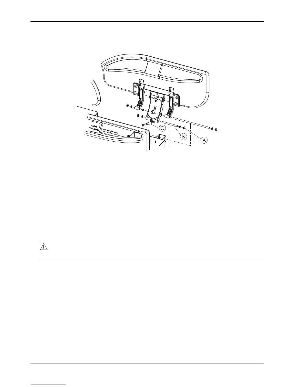
Service
Foot end siderail gas cylinder replacement (Continued)
Figure 9: Foot end siderail gas cylinder
Brake / steer pedal replacement
Tools required:
• Large flat screwdriver
• Hammer
• 3/8 in. drive ratchet
• 13 mm socket
• 13 mm combination wrench
Procedure:
1. Put the brake in the neutral position.
CAUTION
With the brake in the neutral position, the product could move.
2. Raise the product to the highest height position.
3. Power down the bed and unplug the power cord from the wall outlet.
4. Using a 3/8 in. drive ratchet and 13 mm socket with a 13 mm combination wrench, remove and save the bolt (A)
and nut (B) that secures the linkage to the brake / steer pedal (Figure 10 on page 57).
5. Using a large flat screwdriver and a hammer, remove and discard the push nut (C) that secures the brake / steer
pedal on the hex shaft (Figure 10 on page 57).
6. Remove and discard the brake/steer pedal (D) (Figure 10 on page 57).
7. Reverse steps to reinstall.
8. Verify proper operation of the product before returning it to service.
56 SM-7100 REV 01 www.stryker.com
Page 61
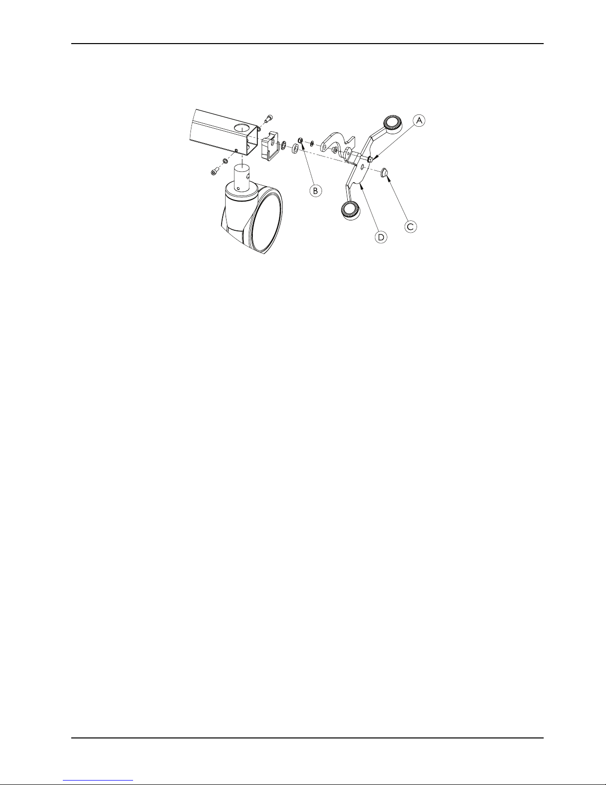
Service
Brake / steer pedal replacement (Continued)
Figure 10: Brake / steer pedal
Lower leg section locking mechanism replacement
Tools required:
• 3/8 in. drive ratchet
• 13 mm socket
• 13 mm combination wrench
Procedure:
1. Apply the brakes.
2. Raise the product to the highest height position.
3. Power down the bed and unplug the power cord from the wall outlet.
4. Raise the lower leg section (A) (Figure 11 on page 58).
5. Lock the lower leg section.
Note: If you cannot lock the lower leg section, find another way to support the lower leg section.
6. Using a 13 mm combination wrench and a 13 mm socket, remove and save the upper bolt and nut that secure the
lower leg section locking mechanism (B) to the foot section weldment (Figure 11 on page 58).
7. Using a 13 mm socket, remove and save the bolt (C), washers (D, E), and nut (F) that secures the bottom of the
lower leg section locking mechanism to the litter frame (Figure 11 on page 58).
8. Remove and discard the lower leg section locking mechanism (B) (Figure 11 on page 58).
9. Reverse steps to reinstall.
10. Verify proper operation of the product before returning it to service.
www.stryker.com SM-7100 REV 01 57
Page 62
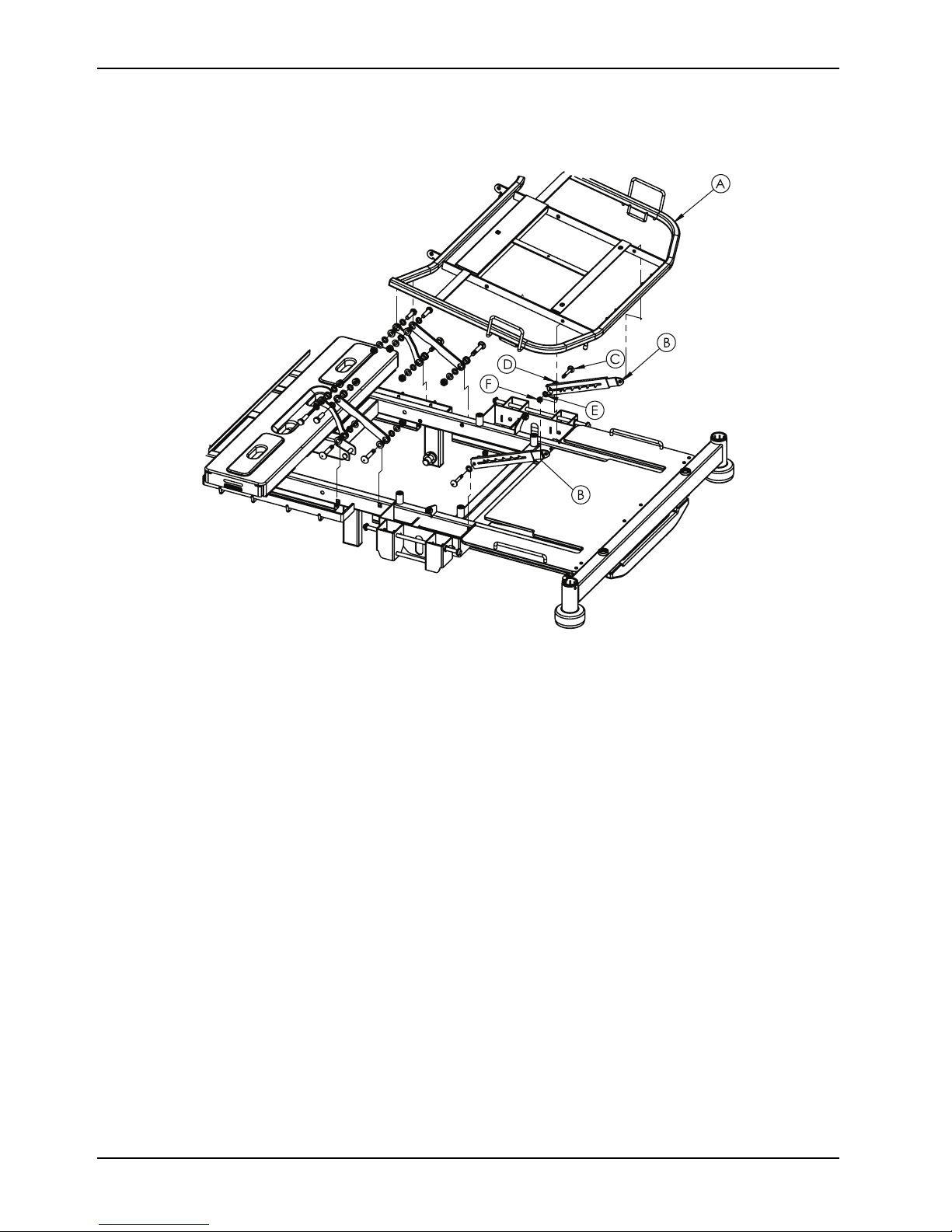
Service
Lower leg section locking mechanism replacement (Continued)
Figure 11: Lower leg section locking mechanism
Patient control pendant replacement
Tools required:
• Diagonal pliers
Procedure:
1. Apply the brakes.
2. Raise the product to the highest height position.
3. Power down the bed and unplug the power cord from the wall outlet.
4. Remove the three cable routing covers that secure the gatch (legrest) actuator cable to the litter frame.
5. Cut the cable tie that secures the pendant to the bottom of the litter frame.
6. Unplug the patient control pendant cable from the junction box.
7. Dispose of the patient control pendant.
8. Reverse steps to reinstall.
9. Verify proper operation of the product before returning it to service.
Nurse control pendant replacement
Tools required:
• Diagonal pliers
58 SM-7100 REV 01 www.stryker.com
Page 63

Service
Nurse control pendant replacement (Continued)
Procedure:
1. Apply the brakes.
2. Raise the product to the highest height position.
3. Power down the bed and unplug the power cord from the wall outlet.
4. Using diagonal pliers, cut and discard the cable tie that secures the fowler (backrest) actuator cable to the wire
routing channel.
5. Remove the three cable routing covers that secure the gatch (legrest) actuator cable to the litter frame.
6. Unplug the nurse control pendant cable from the junction box.
7. Dispose of the nurse control pendant.
8. Reverse steps to reinstall.
9. Verify proper operation of the product before returning it to service.
Siderail control panel (inside and outside siderail) replacement
Tools required:
• Flat screwdriver
Procedure:
1. Apply the brakes.
2. Raise the product to the highest height position.
3. Power down the bed and unplug the power cord from the wall outlet.
4. Remove the part number label from the head side of the control box assembly.
5. Using a flat screwdriver, carefully pry the outer panel away from the siderail hoop until the hoop fully unsnaps from
the inner panel.
6. Unplug the cable connecting the siderail control panel to the junction box.
7. Remove and discard the siderail control panel.
8. Reverse steps to reinstall.
9. Verify proper operation of the product before returning it to service.
Control box replacement
Tools required:
• Diagonal pliers
• Small flat screwdriver
• 3/8 in. drive ratchet
• 10 mm socket
• 10 mm combination wrench
Procedure:
1. Apply the brakes.
2. Raise the product to the highest height position.
3. Power down the bed and unplug the power cord from the wall outlet.
4. Turn the battery off using the nurse control.
5. Raise and lock the lower leg section in the highest position.
6. Using a small flat screwdriver, un-clip the actuator cable retainer (A) from the control box (Figure 12 on page 60).
7. Remove and save the actuator cable retainer.
www.stryker.com SM-7100 REV 01 59
Page 64

Service
Control box replacement (Continued)
8. Using a small flat screwdriver, push in on the power cord lock and gently pull outward on the power cord.
9. Remove the power cord from the control box.
10. Unplug the control cables and the battery cable from the control box.
Note: Pay attention to the control cable connection locations for reinstallation.
11. Using a 10 mm combination wrench and a 10 mm socket, remove the bolt (B) that secures the control box to the
litter frame (Figure 12 on page 60).
12. Remove and discard the control box.
13. Reverse steps to reinstall.
14. Verify proper operation of the product before returning it to service.
Figure 12: Control box
Battery replacement
Tools required:
• Diagonal pliers
• #2 Phillips screwdriver
Procedure:
1. Apply the brakes.
2. Raise the product to the highest height position.
3. Power down the bed and unplug the power cord from the wall outlet.
4. Remove the cable routing cover that secures the gatch (legrest) actuator cable to the litter frame.
5. Using diagonal pliers, cut and discard the cable tie that secures the battery cable to all of the actuator cables.
6. Using a #2 Phillips screwdriver, unscrew the four screws (A) that secure the battery to the litter frame (Figure 13 on
page 61).
Note: Support the battery while removing the screws so the battery does not fall.
60 SM-7100 REV 01 www.stryker.com
Page 65

Service
Battery replacement (Continued)
7. Remove the battery.
8. Dispose of the battery according to local laws and procedures.
9. Reverse steps to reinstall.
10. Verify proper operation of the product before returning it to service.
Figure 13: Battery
Power cord replacement
Tools required:
• Diagonal pliers
• Small flat screwdriver
Procedure:
1. Apply the brakes.
2. Raise the product to the highest height position.
3. Power down the bed and unplug the power cord from the wall outlet.
4. Remove the three cable routing covers that secure the power cord to the litter frame.
5. Using diagonal pliers, cut the five cable ties that secure the power cord to the litter frame.
6. Using a small flat screwdriver, push in on the power cord lock and gently pull outward on the power cord.
7. Remove and discard the power cord from the control box.
8. Reverse steps to reinstall.
9. Verify proper operation of the product before returning it to service.
www.stryker.com SM-7100 REV 01 61
Page 66

Service
Head end siderail hoop replacement
Tools required:
• #2 Phillips screwdriver
• Flat screwdriver
Procedure:
1. Apply the brakes.
2. Raise the product to the highest height position.
3. Power down the bed and unplug the power cord from the wall outlet.
4. Raise the siderail to the full upright and latched position.
5. Remove the mattress.
6. Remove the part number label from the head side of the control box assembly.
7. Using a flat screwdriver, carefully pry the outer panel away from the siderail hoop until the hoop fully unsnaps from
the inner panel.
8. Unplug the cable connecting the siderail control panel to the control box.
9. Remove the siderail control panel.
10. Using a #2 Phillips screwdriver, remove and save the cover screw on the bottom of the siderail hoop on either side
of the siderail pivot.
11. Using a flat screwdriver, carefully pry outward on the siderail pivot cover.
12. Using a #2 Phillips screwdriver, remove and discard the four screws (A) that secure the siderail hoop (B) to the
siderail mechanism (Figure 14 on page 62).
Note: Support the siderail hoop while removing the screws so the siderail hoop does not fall.
13. Remove and discard the siderail hoop.
14. Reverse steps to reinstall.
15. Verify proper operation of the product before returning it to service.
62 SM-7100 REV 01 www.stryker.com
Figure 14: Head end siderail hoop
Page 67

Service
Foot end siderail hoop replacement
Tools required:
• #2 Phillips screwdriver
• Flat screwdriver
Procedure:
1. Apply the brakes.
2. Raise the product to the highest height position.
3. Power down the bed and unplug the power cord from the wall outlet.
4. Raise the siderail to the full upright and latched position.
5. Remove the mattress.
6. Using a #2 Phillips screwdriver, remove and save the cover screw on the bottom of the siderail hoop on either side
of the siderail pivot.
7. Using a flat screwdriver, carefully pry outward on the siderail pivot cover.
8. Using a #2 Phillips screwdriver, remove and discard the four screws (A) that secure the siderail hoop (B) to the
siderail mechanism (Figure 15 on page 63).
Note: Support the siderail hoop while removing the screws so the siderail hoop does not fall.
9. Remove and discard the siderail hoop.
10. Reverse steps to reinstall.
11. Verify proper operation of the product before returning it to service.
www.stryker.com SM-7100 REV 01 63
Figure 15: Foot end siderail hoop
Page 68

Brake system
Item Number Name
A HM-01-26 150 mm standard twin
B HM-01-25 150 mm directional lock
C
D HM-09-04 6 mm serrated washer
E YM-HM-02-299
64 SM-7100 REV 01 www.stryker.com
HM-05-106 M6*16 imbus bolt 8
caster
twin caster
(ring) DIN 6798
50 x 50 caster profile cap
PLS
Quantity
3
1
8
4
Page 69

Brake system
Item Number Name
F HM-11-10 11 mm snap ring (lipper)
KMS starlock push on
BV/6706 fastener
G
H HM-11-20
I
J YN-FUTURELBAKT-001-
L HM-05-135 6 X 20 mm steel bolt
M HM-12-905
N HM-07-22 M6 iron washer (small)
O
P YM-FUTURELBPDL-001-BYFuture LB pedal white
Y YM-HM-02-62 Red brake rubber MKA062
Z YM-HM-02-63
YM-HM-02-71
YM-03-04-10-0760-GL
BY
HM-08-05
12 mm thick PLS washer
DMR 071
Q11 capped snap ring
DT/6673/44A
760 mm hexagonal
galvanized bar
Brake transfer bar left
Transfer laser cut part
bushing (bronz)
M6 fibered nut
DMR062
Green brake rubber
MKA063 DMR063
Quantity
4
4
4
2
2
4
4
4
4
4
4
4
www.stryker.com SM-7100 REV 01 65
Page 70

Base and leg assembly
Item Number Name
A YM-FUTURELBANA-004-
BY
B YM-FUTURELBANA-002-
BY
C
D YM-HM-02-396 Delrin slider blocks
E HM-12-FTR004 12-FTR004 10 x 53
F HM-02-285
G
H HM-05-153
I HM-02-283 2 mm plastic washer (10
66 SM-7100 REV 01 www.stryker.com
YM-HM-02-402
HM-11-03 10 mm snap ring DIN 471 2
Head end lift leg weldment
Foot end lift leg weldment
Ø34 mm plastic bushing
actuator pin
Ø10.6 x 7.5 mm plastic
washer
Ø10 x 35 mm button head
bolt
mm plastic washer) mould
NO 34
Quantity
1
1
4
4
2
2
4
4
Page 71

Base and leg assembly
Item Number Name
J HM-12-FTR007
K YM-HM-02-398
L YM-04-FTR011-HZR-BY Timing link 2
M YM-HM-02-399
N HM-09-18 M10 rivet nut
O
P YM-FUTURELBALT-002-
HM-08-07
MN1
Ø10.2 mm plastic bushing
Ø14.5 x 8 mm plastic
washer
Ø14 x 2 mm plastic washer
M10 fiber hex nut
Base assembly
Quantity
4
4
4
4
4
1
www.stryker.com SM-7100 REV 01 67
Page 72

Litter / frame assembly
Item Number Name
A
B YM-026-010-MN Head end weldment
C
D YM-FUTURELBALT-002-
E YM-FUTURELBANA-002-
F YM-FUTURELBANA-004-
G
H HM-07-04 M10 iron washer 8
I HM-08-07
J HM-07-07
K HM-06-02
L YM-16-49-03 380 mm cable routing
M YM-16-49-01 530 mm cable routing
N YM-16-49-02 660 mm cable routing
O
YM-FUTURELBUST-001-BYLitter frame weldment
YM-039-004-MN Bed extender
Base assembly
MN1
Foot end lift leg weldment
BY
Head end lift leg weldment
BY
HM-05-006
HM-22-61
Ø10 x 70 mm pin
M10 fiber hex nut
Ø4 iron washer
Ø3.9 x 15 mm
cover
cover
cover
660 mm ?
Quantity
1
1
1
1
1
1
4
4
8
8
2
2
2
2
68 SM-7100 REV 01 www.stryker.com
Page 73

Litter / frame assembly
Item Number Name
P HM-06-09
Q
R HM-02-417
S
T YM-HM-02-401
U HM-12-FTR004 12-FTR004 10 x 53
V HM-02-285
W HM-11-03 10 mm snap ring DIN 471 2
YM-HM-02-408
HM-20-840 Bed extender pin 2
Ø3.9 x 25 mm
Ø20 x 32 mm gatch
(footrest) bumper
300 x 18 x 16 mm footrest
bumper
Delrin C spacer
actuator pin
Ø10 x 7.5 mm plastic
washer
Quantity
6
4
1
2
2
2
www.stryker.com SM-7100 REV 01 69
Page 74

Bumper roller assembly
Item Number Name
A YM-HM-02-413
B HM-12-128
C
D
E HM-06-02
F HM-02-354
G HM-12-FTR001
H HM-02-391
I HM-02-55
J YM-04-322-HZR-1
K
HM-09-04
YM-04-100-HZR3
YM-04-322-HZR
Accessory socket sleeve
Grounding chrome
6 mm serrated washer
(ring) DIN 6798
Cable stow 20b-3
Star drive round head bolt
(3.9 x 13 mm)
Future bumper
12-FT001 future bumper
pin
5 mm C shaped snap ring
DIN 6799
Head board lock pin plastic
encasing
Detachable bumper to
chassis connection arm
(right side)
Detachable bumper
chassis to main chassis
connection arm (left side)
Quantity
2
1
1
1
2
2
2
2
2
1
1
L YM-03-01-01-01250-HZR
M YM-03-02-41-877-HZR1
70 SM-7100 REV 01 www.stryker.com
45 x 2 x 150 mm bumper
chassis side tubes
Main bumper profile 40 x
60 x 877 mm
2
1
Page 75

Bed extender assembly
Item Number Name
A YM-27-01-106
B YM-039-004-00-BY Bed extender weldment
C
D
E HM-06-82 M14 x 12 mm Phillips
F
G
H YM-HM-02-413 Accessory socket sleeve 2
I HM-02-354 Future bumper 2
J HM-12-FTR001
www.stryker.com SM-7100 REV 01 71
YM-20-011 Plastic linen tray
YM-UZTMSLTTC-001
YM-UZTMCIRT-MN
HM-06-63 M14 x 16 mm Phillips
HPL footrest extension
Bolster mattress retainers 2
screw
Bolster mattress Velcro®
screw
12-FT001 future bumper
pin
Quantity
1
1
1
6
1
6
2
Page 76

Bed extender assembly
Item Number Name
K HM-11-05
L YM-02-55 Footboard pin socket 2
M HM-08-38 M4 hex nut 2
N YM-HM-02-416
O
P YM-04-FTR023-HZR-BY HPL extension mounting
Q
R HM-06-02
S
T HM-03-04-03-0650-HZR-
YM-HM-02-415 Bed extender block stops 2
YM-04-FTR022-HZR-BY HPL extension mounting
HM-08-19 M4 x .7 nylock nut
BY
6 mm C shape snap ring
DIN 6799
Litter frame plastic end
caps
bracket
bracket
Ø3.9 x 13 mm Phillips
screw
Ø8 mm linen tray bar
Quantity
2
2
2
1
6
4
1
72 SM-7100 REV 01 www.stryker.com
Page 77

Hi-Lo actuators
Item Number Name
J03648 (31410H
A HM-17-100
B
C HM-12-FTR004
D
E HM-12-112
HM-11-03
HM-02-285
+1115004K CB16 Linak
high/low actuator)
10 mm snap ring DIN 471
12-FTR004 10 x 53
actuator pin
10 x 7.5 mm plastic washer
12-112 Ø10 x 39.5 mm
stepped pin
Quantity
2
4
2
2
2
www.stryker.com SM-7100 REV 01 73
Page 78

Control box and battery
Item Number Name
A
B HM-05-043 M5*20 imbus bolt 4
C
D
E
F
G
H HM-05-010 M6*50 steel bolt 1
I
J
K
HM-17-16 BA1812-1300-000 Linak
CB6 battery
HM-07-22 M6 iron washer (small)
HM-08-04
YM-03-03-01-0425-HZR 5 x 20 mm battery
HM-06-049
HM-17-373
HM-08-05
HM-17-174
HM-06-02
M5 fibered nut 4
mounting bracket
3.9 x 16 mm pan head self
drilling screw
QFUTURE LB CB6 control
box new type system
(CB6S674+X4409) CB6663-
00 100-240 volt
M6 fibered nut 1
Control box mounting
bracket
3.9 x 13 mm pan head self
drilling screw
Quantity
1
6
2
4
1
1
2
L
74 SM-7100 REV 01 www.stryker.com
HM-07-01 M6 metal standard washer
(large) 1/4 washer
2
Page 79

Litter fowler (backrest) assembly
Item Number Name
A YM-27-01-005 Plastic backrest cover
B YM-008-013-00-BY Backrest weldment
C YM-FUTURESRT-001-BY Siderail mounting bracket
D YM-04-102-BY 102-6 laser cut link 2
E YM-04-103-BY 103-6 laser cut link 2
F HM-02-13
G
H HM-06-30
I YM-15-05-0450-HZR1 X-Ray cassette track 2
J HM-08-06
K HM-07-03 M8 iron washer
L HM-05-018
HM-05-032 M8 x 20 mm countersunk
Red plastic CPR release
handle
bolt
M5 x 15 mm self drilling
star bolt
M8 fibered nut
M8*90 half thread steel
bolt
Quantity
1
1
2
2
6
4
2
4
2
www.stryker.com SM-7100 REV 01 75
Page 80

Litter fowler (backrest) assembly
Item Number Name
M HM-08-35 M8 rivet nut 6
N HM-11-03 10 mm snap ring DIN 471 2
O
P HM-12-103
Q
R HM-05-005
S
T HM-07-04 M10 iron washer 8
U HM-08-07
V HM-06-89 M10 x 55 mm carriage bolt
W
HM-02-283 2 mm plastic washer (10
mm plastic washer) mould
NO 34
Ø10 x 44.5 mm pin
HM-06-72
YM-HM-02-88
YM-FUTURELBUST-001-BYLitter frame weldment
Ø5.5 x 19mm torque screw
Ø10 x 35 mm hex head bolt
Ø10 mm plastic bushing
M10 fiber hex nut
Quantity
14
2
6
4
8
8
4
1
76 SM-7100 REV 01 www.stryker.com
Page 81

Litter seat assembly
Item Number Name
A HM-02-120 Plastic seat cover
B
YM-FUTURELBUST-001-BYLitter frame weldment
Quantity
1
1
www.stryker.com SM-7100 REV 01 77
Page 82

Litter gatch (legrest) assembly
Item Number Name
A HM-02-121
B HM-02-119 Plastic thigh rest cover
C
D YM-006-003-BY Thigh rest weldment
E HM-20-517 Foot prop assembly 2
F YM-04-102-BY 102-6 laser cut link 2
G
H YM-HM-02-179 Bolt cap
I HM-08-07
J HM-07-04 M10 iron washer 12
K HM-02-283 2 mm plastic washer (10
L HM-06-89 M10 x 55 mm carriage bolt
M YM-HM-02-88
N HM-05-005 M10 x 35 mm hex head
YM-007-006-BY
YM-04-103-BY 103-6 laser cut link 2
Plastic calf rest cover
Calf rest weldment
M10 fiber hex nut
mm plastic washer) mould
NO 34
Ø10 mm plastic bushing
bolt
Quantity
1
1
1
1
4
10
12
4
8
4
78 SM-7100 REV 01 www.stryker.com
Page 83

Litter gatch (legrest) assembly
Item Number Name
O
P HM-07-03 M8 iron washer 2
Q
R HM-06-66 M6 x 15 mm button head
S
T
HM-06-88 M8 x 47 mm carriage bolt 2
HM-08-06
YM-HM-02-55
YM-FUTURELBUST-001-BYLitter frame weldment
M8 fibered nut
screw
Ø9 x 12.4 mm plastic
screw
Quantity
2
1
2
1
www.stryker.com SM-7100 REV 01 79
Page 84

Fowler (backrest) actuator
Item Number Name
312887-00 future LB
A HM-17-248
B
C HM-12-FTR004
HM-11-03
release backrest actuator
Linak type
10 mm snap ring DIN 471
12-FTR004 10 x 53
actuator pin
Quantity
1
2
2
80 SM-7100 REV 01 www.stryker.com
Page 85

Gatch (legrest) actuator
Item Number Name
A
B HM-11-03
D
E HM-12-FTR006
F HM-02-287
G HM-02-283
H
HM-17-249
HM-12-FTR004
HM-02-285 7 mm PLS washer 2
J04257 future LB legrest
actuator Linak type
10 mm snap ring DIN 471
12-FTR004 10 x 53
actuator pin
12-FTR006 calf pin
10 x 14 mm plastic washer
2 mm plastic washer (10
mm plastic washer) mould
NO 34
Quantity
1
3
1
1
2
2
www.stryker.com SM-7100 REV 01 81
Page 86

Siderail head end assembly
Item Number Name
A YM-20-005
B YM-20-007 Head end right siderail
C
D HM-02-283 2 mm plastic washer (10
E HM-12-145 12-145 10 x 305 mm
F HM-12-144 12-144 10 x 128 mm
Siderail laminate
Dark blue HM-20-853 HM-20-852
Dark wood HM-20-760 HM-20-759
HM-11-19
Number (left) Number (right)
Head end left siderail
Q10 capped snap ring
(DT/6668/44A)
mm plastic washer) mould
NO 34
siderail pin
siderail pin
Quantity
1
1
16
24
4
4
82 SM-7100 REV 01 www.stryker.com
Page 87

Siderail head end assembly
Siderail laminate
Light wood HM-20-750 HM-20-749
Wood HM-20-755 HM-20-754
Number (left) Number (right)
www.stryker.com SM-7100 REV 01 83
Page 88

Siderail assembly
Item Number Name
A
B
C
D HM-06-23
E YM-HM-02-394
F YM-HM-02-363
G YM-HM-02-362
H HM-12-145
I HM-12-144
J HM-11-04
K HM-18-27
L HM-12-146
YM-20-007
HM-04-FTR005
YM-FUTUREALMKL-001BY
Head end right siderail
Siderail assembly base
metal
Aluminum siderail arm
(white)
M6 x 10 mm countersunk
bolt
Siderail mechanism cover
1 left -mould 81
Siderail mechanism cover
2 right - mould 81
Siderail mechanism cover
3 center - mould 67
12-145 10 x 305 mm
siderail pin
12-144 10 x 128 mm
siderail pin
8 mm snap ring
Future side rail shock
absorber 640015004
12-146 8 x 31 mm side rail
pin
Quantity
1
1
2
6
1
1
1
1
1
2
1
1
M HM-11-18
N YM-HM-02-369
84 SM-7100 REV 01 www.stryker.com
Q8 capped snap ring
(DT/6671/43A)
Siderail plastic main
mechanism housing
2
1
Page 89

Siderail foot end assembly
Item Number Name
C
D HM-02-283 2 mm plastic washer (10
E HM-12-145 12-145 10 x 305 mm
F HM-12-144 12-144 10 x 128 mm
G
H YM-20-008 Foot end right siderail
Siderail laminate
Dark blue HM-20-855 HM-20-854
Dark wood HM-20-762 HM-20-761
Light wood HM-20-752 HM-20-751
Wood HM-20-757 HM-20-756
HM-11-19
YM-20-006
Q10 capped snap ring
(DT/6668/44A)
mm plastic washer) mould
NO 34
siderail pin
siderail pin
Foot end left siderail
Number (left) Number (right)
Quantity
16
24
4
4
1
1
www.stryker.com SM-7100 REV 01 85
Page 90

Siderail release latch assembly
Item Number Name
A HM-11-05
B HM-12-200
C HM-11-06
D HM-12–147
E HM-06–14 Ø3.5 x 13 mm Star screw 2
F HM-16–51
G HM-02-370
H HM-02-374 Siderail release handle 1
I
J HM-02-369
86 SM-7100 REV 01 www.stryker.com
HM04-FTR007 Siderail release hammer 1
6 mm C shape snap ring
DIN 6799
Ø8 x 98 mm siderail pin
with snap ring slides
Size 4 snap ring
Ø5 x 98 mm siderail pin
with snap ring slides
Hammer spring
Siderail mechanism plastic
cover
Siderail mechanism plastic
shell
Quantity
2
1
2
1
1
1
1
Page 91

Headboard and footboard assembly
Item Number Name
A HM-06-49
B HM-12-150
C YM-20-013
Headboard laminate Number
Dark blue HM-20-851
Dark wood HM-20-763
Light wood HM-20-753
Wood HM-20-758
Footboard laminate Number
Dark blue HM-20-850
Dark wood HM-20-763
Light wood HM-20-753
Wood HM-20-758
3.9 x 16 mm drill head
smart screw
Ø18 x 4 mm head pipe
Head or foot board
polypropylene
Quantity
4
2
1
www.stryker.com SM-7100 REV 01 87
Page 92

Recycling passports
Assembly part number: HM-17-164 (Reference only)
Item
A HM-17-164 Power cable 1
Recycling/Material Code Important Qty
88 SM-7100 REV 01 www.stryker.com
Page 93

Assembly part number: HM-17-373 (Reference only)
Item
Recycling/Material Code Important Quantity
A HM-17-373
www.stryker.com SM-7100 REV 01 89
Control panel
1
Page 94

Assembly part number: HM-17-16 (Reference only)
A
Item
A HM-17-16
Recycling/Material Code Important Quantity
Battery
1
90 SM-7100 REV 01 www.stryker.com
Page 95

Assembly part number: HM-17-156 (Reference only)
Item
Recycling/Material Code Important Quantity
A HM-17-156
www.stryker.com SM-7100 REV 01 91
Multi-junction box
1
Page 96

Assembly part number: YM-26-31 (Reference only)
Item
A
Recycling/Material Code Important Quantity
YM-26-31
Siderail control panel
1
92 SM-7100 REV 01 www.stryker.com
Page 97

Assembly part number: HM-17-168 (Reference only)
Item
Recycling/Material Code Important Quantity
A HM-17-168
Nurse control pendant
1
www.stryker.com SM-7100 REV 01 93
Page 98

Assembly part number: HM-17-219 (Reference only)
Item
Recycling/Material Code Important Quantity
A HM-17-219
94 SM-7100 REV 01 www.stryker.com
Patient control pendant
1
Page 99

Assembly part number: HM-17-100 (Reference only)
Item
Recycling/Material Code Important Quantity
A HM-17-100 Hi-lo actuator 1
B HM-17-100 Hi-lo actuator 1
www.stryker.com SM-7100 REV 01 95
Page 100

Assembly part number: HM-17-248 (Reference only)
Item
Recycling/Material Code Important Quantity
A HM-17-248
96 SM-7100 REV 01 www.stryker.com
Fowler / backrest actuator
1
 Loading...