

Page 1
Operations/
Maintenance
Manual
Important
Information
File in your
maintenance
records
Medical
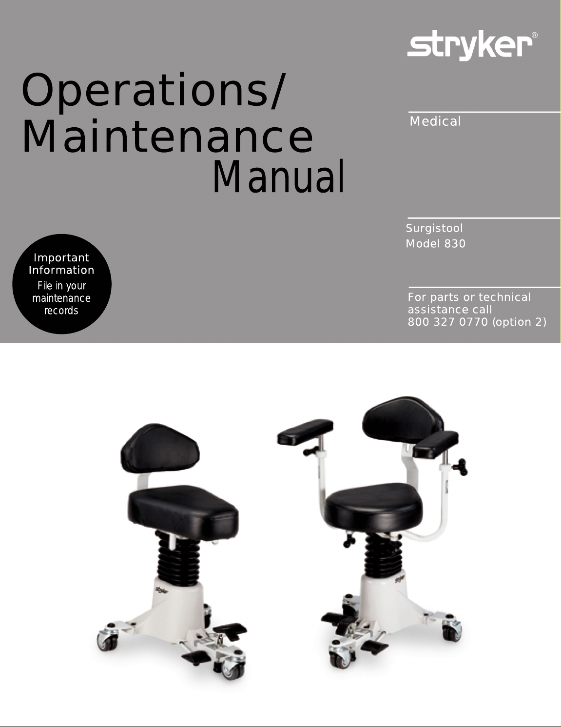
Surgistool
Model 830
For parts or technical
assistance call
800 327 0770 (option 2)
Page 2

Table of Contents
Introduction
Specifications 2. . . . . . . . . . . . . . . . . . . . . . . . . . . . . . . . . . . . . . . . . . . . . . . . . . . . . . . . . . . . . . . . . . . . . . . . . .
Warning / Caution / Note Definition 2. . . . . . . . . . . . . . . . . . . . . . . . . . . . . . . . . . . . . . . . . . . . . . . . . . . . . . . .
Base Pedal Operation 3. . . . . . . . . . . . . . . . . . . . . . . . . . . . . . . . . . . . . . . . . . . . . . . . . . . . . . . . . . . . . . . . . . . . . . .
Adjusting The Back Rest 4. . . . . . . . . . . . . . . . . . . . . . . . . . . . . . . . . . . . . . . . . . . . . . . . . . . . . . . . . . . . . . . . . . . .
Adjusting The Optional Wrist Rests 4. . . . . . . . . . . . . . . . . . . . . . . . . . . . . . . . . . . . . . . . . . . . . . . . . . . . . . . . . . .
Preventative Maintenance 5. . . . . . . . . . . . . . . . . . . . . . . . . . . . . . . . . . . . . . . . . . . . . . . . . . . . . . . . . . . . . . . . . . .
Cleaning 6. . . . . . . . . . . . . . . . . . . . . . . . . . . . . . . . . . . . . . . . . . . . . . . . . . . . . . . . . . . . . . . . . . . . . . . . . . . . . . . . . .
Hydraulic System Troubleshooting 7. . . . . . . . . . . . . . . . . . . . . . . . . . . . . . . . . . . . . . . . . . . . . . . . . . . . . . . . . . . .
Removing Excess Air From The Hydraulic System 7. . . . . . . . . . . . . . . . . . . . . . . . . . . . . . . . . . . . . . . . . . . . . .
Jack Descent Rate Adjustment 7. . . . . . . . . . . . . . . . . . . . . . . . . . . . . . . . . . . . . . . . . . . . . . . . . . . . . . . . . . . . . . .
Checking Hydraulic Fluid Level 8. . . . . . . . . . . . . . . . . . . . . . . . . . . . . . . . . . . . . . . . . . . . . . . . . . . . . . . . . . . . . . .
Base Hood Removal 9. . . . . . . . . . . . . . . . . . . . . . . . . . . . . . . . . . . . . . . . . . . . . . . . . . . . . . . . . . . . . . . . . . . . . . . .
Hydraulic Valve Replacement 9. . . . . . . . . . . . . . . . . . . . . . . . . . . . . . . . . . . . . . . . . . . . . . . . . . . . . . . . . . . . . . . .
Brake Adjustment 9. . . . . . . . . . . . . . . . . . . . . . . . . . . . . . . . . . . . . . . . . . . . . . . . . . . . . . . . . . . . . . . . . . . . . . . . . .
Quick Reference Replacement Parts List 10. . . . . . . . . . . . . . . . . . . . . . . . . . . . . . . . . . . . . . . . . . . . . . . . . . . . .
Assembly Drawings And Parts Lists
Seat to Base Assembly 11. . . . . . . . . . . . . . . . . . . . . . . . . . . . . . . . . . . . . . . . . . . . . . . . . . . . . . . . . . . . . . . . .
Motorcycle Seat to Base Assembly 12. . . . . . . . . . . . . . . . . . . . . . . . . . . . . . . . . . . . . . . . . . . . . . . . . . . . . . .
Round & Obround Seat Assembly 13. . . . . . . . . . . . . . . . . . . . . . . . . . . . . . . . . . . . . . . . . . . . . . . . . . . . . . . .
Motorcycle Seat Assembly 14. . . . . . . . . . . . . . . . . . . . . . . . . . . . . . . . . . . . . . . . . . . . . . . . . . . . . . . . . . . . . .
Base Assembly 16, 17. . . . . . . . . . . . . . . . . . . . . . . . . . . . . . . . . . . . . . . . . . . . . . . . . . . . . . . . . . . . . . . . . . . . .
Jack Assembly 18−20. . . . . . . . . . . . . . . . . . . . . . . . . . . . . . . . . . . . . . . . . . . . . . . . . . . . . . . . . . . . . . . . . . . . .
Pump Pedal Assembly 21. . . . . . . . . . . . . . . . . . . . . . . . . . . . . . . . . . . . . . . . . . . . . . . . . . . . . . . . . . . . . . . . .
Release Pedal Assembly 22. . . . . . . . . . . . . . . . . . . . . . . . . . . . . . . . . . . . . . . . . . . . . . . . . . . . . . . . . . . . . . .
Brake Assembly 23. . . . . . . . . . . . . . . . . . . . . . . . . . . . . . . . . . . . . . . . . . . . . . . . . . . . . . . . . . . . . . . . . . . . . . .
Optional Back Rest Assembly 24. . . . . . . . . . . . . . . . . . . . . . . . . . . . . . . . . . . . . . . . . . . . . . . . . . . . . . . . . . .
Optional Wrist Rest Assembly 25. . . . . . . . . . . . . . . . . . . . . . . . . . . . . . . . . . . . . . . . . . . . . . . . . . . . . . . . . . .
Optional Seat Riser Assembly 26. . . . . . . . . . . . . . . . . . . . . . . . . . . . . . . . . . . . . . . . . . . . . . . . . . . . . . . . . . .
Limited Warranty
Obtaining Parts and Service 27. . . . . . . . . . . . . . . . . . . . . . . . . . . . . . . . . . . . . . . . . . . . . . . . . . . . . . . . . . . . .
Supplemental W
Return Authorization 28. . . . . . . . . . . . . . . . . . . . . . . . . . . . . . . . . . . . . . . . . . . . . . . . . . . . . . . . . . . . . . . . . . .
Freight Damage Claims 28. . . . . . . . . . . . . . . . . . . . . . . . . . . . . . . . . . . . . . . . . . . . . . . . . . . . . . . . . . . . . . . . .
arranty Coverage 27. . . . . . . . . . . . . . . . . . . . . . . . . . . . . . . . . . . . . . . . . . . . . . . . . . . . . . . .
Page 3

Introduction
INTRODUCTION
This manual is designed to assist you with the operation and maintenance of the Model 830 Surgistool II.
Read it thoroughly before using the equipment or beginning any maintenance on it.
SPECIFICATIONS
Maximum Weight Capacity 300 pounds
Upper/Lower Height Range 28.5 − 21 inches
Upper/Lower Height Range w/2” Riser Kit 30.5 − 23 Inches
Stryker reserves the right to change specifications without notice.
WARNING / CAUTION / NOTE DEFINITION
The words WARNING, CAUTION and NOTE carry special meanings and should be carefully reviewed.
WARNING
Alerts the reader about a situation, which if not avoided, could result in death or serious injury. It may also
describe potential serious adverse reactions and safety hazards.
CAUTION
Alerts the reader of a potentially hazardous situation, which if not avoided, may result in minor or moderate
injury to the user or patient or damage to the equipment or other property. This includes special care necessary for the safe and effective use of the device and the care necessary to avoid damage to a device that
may occur as a result of use or misuse.
NOTE
This provides special information to make maintenance easier or important instructions clearer.
Back to Table of Contents
2
Page 4

BASE PEDAL OPERATION
Operation Guide
A
B
C
SIDE VIEW
(A) Push down to set Surgistool brake. Lift up to release brake.
(B) Pump to raise Surgistool height.
(C) Depress to lower Surgistool height.
Back to Table of Contents
3
Page 5

ADJUSTING THE BACK REST
A
Operation Guide
To adjust the height of the back rest, turn
knob (A) counterclockwise. Slide the
back rest up or down to the desired height.
Turn knob (A) clockwise and tighten until
the back rest is secure.
To move the back rest closer to the seat
or farther away from the seat, turn knob
(B) counterclockwise. Slide the back rest
in or out. Turn knob (B) clockwise until the
back rest is secure.
B
ADJUSTING THE OPTIONAL WRIST RESTS
To adjust the height of the optional wrist rests, turn
knob (A) counterclockwise. Raise or lower the wrist
rest to the desired height. Turn knob (A) clockwise until the wrist rest is secure.
To pivot the wrist rest assembly, turn knob (B) counterclockwise. Pivot the wrist rest to the desired position.
Turn knob (B) clockwise until the wrist rest assembly
is secure.
A
Back to Table of Contents
B
4
Page 6

Preventative Maintenance
CHECKLIST
All fasteners secure (reference all assembly prints)
Brake pedal engages with proper tension (page 9)
All casters secure and swivel properly
Wrist rests swivel and raise properly
No rips or cracks in seat, back rest or wrist rest covers
All adjustment knobs intact and functioning properly
No leaks at hydraulic connections
Hydraulic jack holding properly (page 7)
Hydraulic drop rate set properly (page 7)
Hydraulic oil level sufficient (page 8)
Lubricate where required
Serial No.
Completed By:_________________________________ Date:_____________
NOTE
The serial number label is located under the base frame (see page 11 for reference)
NOTE
Preventative maintenance should be performed at a minimum of annually. A preventative maintenance program should be established for all Stryker Medical equipment. Preventative maintenance may need to be
performed more frequently based on the usage level of the product.
Back to Table of Contents
5
Page 7

Cleaning
Hand wash all surfaces with warm water and mild detergent. Dry thoroughly. DO NOT STEAM CLEAN,
PRESSURE WASH, HOSE OFF OR ULTRASONICALLY CLEAN. Using these methods of cleaning is not
recommended and may void this product’s warranty.
In general, when used in those concentrations recommended by the manufacturer, either phenolic type or
quaternary type disinfectants can be used. Iodophor type disinfectants are not recommended for use because staining may result. The following products have been tested and have been found not to have a harmful effect WHEN USED IN ACCORDANCE WITH MANUFACTURERS RECOMMENDED DILUTION.*
TRADE NAME
A33 Quaternary Airwick (Professional Products Division) 2 ounces/gallon
A33 (dry) Quaternary Airwick (Professional Products Division) 1/2 ounce/gallon
Beaucoup Phenolic Huntington Laboratories 1 ounce/gallon
Blue Chip Quaternary S.C. Johnson 2 ounces/gallon
Elimstaph Quaternary Walter G. Legge 1 ounce/gallon
Franklin Phenomysan F2500 Phenolic Purex Corporation 1 1/4 ounce/gallon
Franklin Sentinel Quaternary Purex Corporation 2 ounces/gallon
Galahad Phenolic Puritan Churchill Chemical Company 1 ounce/gallon
Hi−To r Quaternary Huntington Laboratories 1/2 ounce/gallon
LPH Phenolic Vestal Laboratories 1/2 ounce/gallon
Matar Phenolic Huntington Laboratories 1/2 ounce/gallon
Omega Quaternary Airwick (Professional Products Division) 1/2 ounce/gallon
Quanto Quaternary Huntington Laboratories 1 ounce/gallon
Sanikleen Quaternary West Chemical Products 2 ounces/ gallon
Sanimaster II Quaternary Service Master 1 ounce/gallon
Vesphene Phenolic Vestal Laboratories 1 1/4 ounce/ gallon
DISINFECTANT
TYPE
MANUFACTURER
*MANUFACTURER’S
RECOMMENDED
DILUTION
Quaternary Germicidal Disinfectants, used as directed, and/or Chlorine Bleach products, typically 5.25% Sodium Hypochlorite in dilutions ranging between 1 part bleach to 100 parts water, and 2 parts bleach
to 100 parts water are not considered mild detergents. These products are corrosive in nature and
may cause damage if used improperly. If these types of products are used to clean Stryker equipment,
measures must be taken to insure the unit is rinsed with clean water and thoroughly dried following cleaning.
Failure to properly rinse and dry the unit will leave a corrosive residue on the surface of the unit, possibly
causing premature corrosion of critical components.
NOTE
Failure to follow the above directions when using these types of cleaners may void this product’s warranty.
Back to Table of Contents
6
Page 8

Service Information
HYDRAULIC SYSTEM TROUBLESHOOTING
PROBLEM/SYMPTOM SOLUTION
Jack will not raise to full height. Add hydraulic fluid (see below). Check for leaks.
Jack will not hold in raised position. Close the needle valve completely. If the jack holds,
replace valve (page 9). If the jack does not hold, replace jack.
Jack will not pump up. Remove excess air (vacuum) in system (see below).
If the jack still will not pump up, replace jack.
Contact Stryker technical support at 1−800−327−0770 for further assistance.
REMOVING EXCESS AIR (VACUUM) FROM THE HYDRAULIC SYSTEM
1. Pump the jack completely up and continue to pump the pedal after the jack reaches the top. This will
force the air through the system and the jack should now pump up.
JACK DESCENT RATE ADJUSTMENT
1. Pump the jack up to full height.
2. The descent rate butterfly valve is located on the manifold assembly. Reach under the base hood and
turn the valve clockwise to decrease the rate of descent. Turn it counterclockwise to increase the rate
of descent.
Back to Table of Contents
7
Page 9

Service Information
CHECKING HYDRAULIC FLUID LEVEL
Required Tools:
5/32” Allen Wrench 3/8” Open End Wrench 3/4” Open End Wrench
Needle Nose Pliers
Procedure:
1. Using a 5/32” Allen wrench and a 3/8” open end wrench, remove the four button head cap screws and
four nylock nuts under the seat holding the seat assembly to the base.
2. Using needle nose pliers, remove the cotter pin under the base weldment plate.
3. Remove the base hood (see page 9).
4. Be sure there are no hydraulic leaks. If there are, the hydraulic jack must be replaced.
5. Lower the jack to the full down position.
6. Using a 3/4” open end wrench, slowly turn the fill plug located on the side of the reservoir counterclockwise to allow excess system pressure to vent. Remove the fill plug.
7. The hydraulic fluid should be visible at the bottom of the fill hole. If it is not, add Mobil Aero HFA hydraulic
fluid (Stryker part number 2020−70−475) until the fluid is visible at the bottom of the fill hole. Replace
the fill plug.
CAUTION
Use of other types of oil may damage hydraulic units.
8. Replace the base hood.
Back to Table of Contents
8
Page 10

Service Information
BASE HOOD REMOVAL
Required Tools:
Standard Screwdriver 7/16” Open End Wrench
5/32” Allen Wrench Bungee Cords or String
Procedure:
1. Using a standard screwdriver, pop off the 3 black plastic caps covering the screws holding on the base
hood, being careful not to damage the caps.
2. Remove the nylock nuts, cap screws and washers holding the base hood to the base frame.
3. Lift up the hood and, using bungee cords or string, secure the hood to the bottom of the seat assembly.
4. After service is complete, lower the hood and reinstall the fasteners and protective caps.
HYDRAULIC VALVE REPLACEMENT
B
A
C
BRAKE ADJUSTMENT
Required Tools:
1/2” Open End Wrench
Required Tools:
Standard Screwdriver 3/4” Open End Wrench
Replacement Procedure:
1. Pump the jack fully up and raise the base hood (see above).
2. Turn butterfly valve (A) clockwise to close off the needle valve.
3. Remove the cap screw and washers holding the manifold assembly (B) on the hydraulic jack.
4. Using a 3/4” open end wrench, remove the needle valve (C) from
the manifold assembly.
5. Install the new needle valve, reattach the manifold assembly,
open the butterfly valve and reattach the base hood.
6. Be sure the jack is operating properly before returning the Surgistool to service.
Adjustment Procedure:
1. Loosen the top jam nut (A) on the brake foot assembly.
2. With your fingers, turn the brake shaft assembly (B)
clockwise to loosen the brake tension or counterclockwise
to tighten the brake tension.
3. Tighten the top jam nut when the desired tension is
achieved.
Back to Table of Contents
9
A
B
.032
.000
Page 11

Quick Reference Replacement Parts List
PART NAME PART NUMBER
Brake Assembly 830−10−450. . . . . . . . . . . . . . . . . . . . . . . . . . . . . . . . . . . . . . . . . . . . . . . . . . . . . . . . . . . .
Brake Tip 830−10−451. . . . . . . . . . . . . . . . . . . . . . . . . . . . . . . . . . . . . . . . . . . . . . . . . . . . . . . . . . . . . . . . . .
Hydraulic Jack Assembly w/Control 830−10−70. . . . . . . . . . . . . . . . . . . . . . . . . . . . . . . . . . . . . . . . . . .
Pad, Back Rest 830−20−20. . . . . . . . . . . . . . . . . . . . . . . . . . . . . . . . . . . . . . . . . . . . . . . . . . . . . . . . . . . .
Pad, Wrist Rest 830−40−10. . . . . . . . . . . . . . . . . . . . . . . . . . . . . . . . . . . . . . . . . . . . . . . . . . . . . . . . . . . .
Pedal, Brake 716−1−275. . . . . . . . . . . . . . . . . . . . . . . . . . . . . . . . . . . . . . . . . . . . . . . . . . . . . . . . . . . . . . .
Pedal, Pump & Release 715−1−126. . . . . . . . . . . . . . . . . . . . . . . . . . . . . . . . . . . . . . . . . . . . . . . . . . . . .
Relief Valve, Hydraulic Jack 763−20−34. . . . . . . . . . . . . . . . . . . . . . . . . . . . . . . . . . . . . . . . . . . . . . . . . .
Seat, Motorcycle 763−201−29. . . . . . . . . . . . . . . . . . . . . . . . . . . . . . . . . . . . . . . . . . . . . . . . . . . . . . . . . . .
Seat, Obround Pad 830−30−10. . . . . . . . . . . . . . . . . . . . . . . . . . . . . . . . . . . . . . . . . . . . . . . . . . . . . . . . .
Seat, Tear Drop Pad 830−20−10. . . . . . . . . . . . . . . . . . . . . . . . . . . . . . . . . . . . . . . . . . . . . . . . . . . . . . . .
Seat Riser Kit, 2” 830−201−28. . . . . . . . . . . . . . . . . . . . . . . . . . . . . . . . . . . . . . . . . . . . . . . . . . . . . . . . . . .
T−Handle, Female 24−45. . . . . . . . . . . . . . . . . . . . . . . . . . . . . . . . . . . . . . . . . . . . . . . . . . . . . . . . . .
T−Handle, Male 24−44. . . . . . . . . . . . . . . . . . . . . . . . . . . . . . . . . . . . . . . . . . . . . . . . . . . . . . . . . . . .
Back to Table of Contents
10
Page 12

Seat to Base Assembly, Round & Obround Seat
Assembly part numbers
830−20−101 (Round) &
830−30−101 (Obround)
(reference only)
(ROUND SEAT SHOWN)
Item Part No. Part Name Qty.
A(page 13) Seat Assembly 1
B16−28 Nylock Nut 4
C11−63 Flat Washer 4
D4−193 Hex Soc. But Hd. Cap Scr. 4
E(page 16 & 17) Hydraulic Base Assembly 1
F 830−90−4 Name Plate 1
J 921−1−252 Serial No. Label 1
Back to Table of Contents
11
Page 13

Seat to Base Assembly, Motorcycle Seat
Assembly part number
830−201−20
(reference only)
Item Part No. Part Name Qty.
A(page 14) Motorcycle Seat Assembly 1
B16−28 Nylock Nut 4
C11−63 Flat Washer 4
D4−193 But. Hd. Cap Screw 4
E(page 16 & 17) Hydraulic Base Assembly 1
F 830−90−4 Name Plate 1
G 921−1−252 Serial No. Label 1
Back to Table of Contents
12
Page 14

830−20−100/830−30−100 Seat Assembly, Round/Obround
S1
S2
Item Part No. Part Name Qty.
A 830−20−30 Seat Bracket Weldment 1
B 830−20−34 Backrest Support Bar 1
C 830−20−35 Clamp Weldment 1
D 830−20−38 Wear Strip 4
E 830−20−28 Female Hinge 1
F 830−20−26 Male Hinge and Pin 1
H 830−20−27 Flat Hd. Carriage Bolt 1
J24−45 T−Handle, Female 1
K24−44 T−Handle, Male 1
L12−12 Lockwasher 12
M4−193 Hex Soc. But. Hd. Cap Screw 12
N14−20 Nylon Washer 1
P11−4 Flat Washer 1
R 830−20−25 Hinge Spring 1
S1 830−30−10 Obround Seat Assembly 1
S2 830−20−10 Round Seat Assembly 1
T 830−20−20 Back Rest Assembly 1
W 830−91−3 Rotation Label 1
X38−278 Compression Spring 1
Back to Table of Contents
13
Page 15

830−201−100 Motorcycle Seat Assembly
Item Part No. Part Name Qty. Item Part No. Part Name Qty.
A 830−20−30 Seat Bracket Weldment 1 S 763−201−29 Seat & Mtg. Hardware 1
B 830−20−34 Backrest Support Bar 1 T 830−20−20 Back Rest Assembly 1
C 830−20−35 Clamp Weldment 1 W 830−91−3 Rotation Label 1
D 830−20−38 Wear Strip 4 X 38−278 Compression Spring 1
E 830−20−28 Female Hinge 1 Y 763−201−27 Adjustment Plate 2
F 830−20−26 Male Hinge and Pin 1 AA 11−2 Flat Washer 4
H 830−20−27 Flat Hd. Carriage Bolt 1 AB 3−76 Hex Hd. Cap Screw 2
J24−45 Female T−Handle 1 AC 763−201−28 U−Bracket 1
K24−44 Male T−Handle 1 AF 16−28 Nylock Nut 8
L12−12 Lockwasher 10 AH 763−201−24 Pivot Assembly 2
M4−193 But. Hd. Cap Screw 10 AJ 3−49 Hex Hd. Cap Screw 2
N14−20 Nylon Washer 1 AK 830−21−12 Seat Adapter Weldment 1
P11−4 Flat Washer 1 AL 11−179 Washer 2
R 830−20−25
Back to Table of Contents
Hinge Spring 1
14
Page 16

Notes
Back to Table of Contents
15
Page 17

830−10−100 Base Assembly
Back to Table of Contents
16
Page 18

830−10−100 Base Assembly
Item Part No. Part Name Qty. Item Part No. Part Name Qty.
A 830−10−40 Base Weldment 1 AJ 4−20 Soc. Hd. Cap Screw 4
B(page 18) Jack & Control Assembly 1 AL 763−20−21 Hose Sleeve 3
C 830−10−50 Surgistool II Hood 1 AM 11−63 Flat Washer 11
D 830−10−51 Bellows 1 AN 16−28 Nylock Nut 7
E 830−10−55 Mounting Plate Weldment 1 AP (page 22) Release Pedal Assembly 1
F27−3 Cotter Pin 2 AR 830−10−24 Release Spring 1
H 830−10−180 Pump Link Weldment 1 AS 4−85 Soc. Hd. Cap Screw 2
J(page 21) Pump Pedal Assembly 1 AT 12−5 Lock Washer 2
K28−95 Retaining Ring 2 AW 11−16 Flat Washer 2
L11−4 Flat Washer 3 AY 38−15 Adjustable Clamp 2
M14−20 Plastic Flat Washer 3 AZ 763−20−13 Manifold Mounting Bracket1
N37−196 Protective Cap 3 BA 715−1−133 Spring Guide 1
P4−186 But. Hd. Cap Screw 3 BB 763−1−15 Jack Spring 1
R37−80 Retaining Washer 3 BC 763−1−16 Spring Guide 1
S 830−10−53 Caster 3 BD 390−1−67 Jack Washer 1
T11−13
W16−64 Nylock Nut 3 BF 4−135 But. Hd. Cap Screw 3
Y 830−10−35 Brake Tip 1 BH 37−56 Retaining Washer 3
Z 830−10−34 Foot 1 BJ 946−1−60 Stryker Logo Label 2
AA 11−3 Flat Washer 1 BK 830−90−1 Rear Label 1
AB 14−21 Flat Washer 1 BL 830−90−2 Front Label 1
AD 15−12 Nut 1 BM 830−90−6 Pump Label 1
AF 763−1−33 Brake Nut 1 BN 830−90−7 Release Label 1
AH (page 23)* Brake Assembly 1
* Complete brake assembly (including items AH, Y & Z) is part number 830−10−450. Brake tip and foot assembly (including items Y & Z) is part number 830−10−451.
Flat Washer 3 BE 37−55 Protective Cap 3
Back to Table of Contents
17
Page 19

830−10−70 Jack Assembly
Item Part No. Part Name Qty.
A48−13 Needle Valve 1
B48−146 90° Adjustable Elbow 1
C 390−2−147 L−Fitting 1
D 763−20−23 Return Line 1
E 763−20−34 Replacement Valve Ass’y 1
F(page 19) Jack Assembly 1
G 830−10−71 Pressure Line 1
Back to Table of Contents
18
Page 20

Jack Assembly
Assembly part number 830−10−60 ( reference only)
Item Part No. Part Name Qty. Item Part No. Part Name Qty.
A45−904 Quad Ring 1 P 830−10−62 Actuator Cylinder 1
B 715−1−340 Machined Cap 1 R 390−2−139 Retaining Collar 2
C 390−1−243 Gasket 1 S 390−2−136 Pump Cylinder 1
D 390−2−137 Pump Cap 1 T 390−1−237 Pump Gasket 1
E(page 20) Jack Base Assembly 1 W 830−10−63 Actuator 1
F 390−2−147 ”L” Fitting 1 Y 715−1−331 Piston End 1
H 390−2−128 Packing 1 Z 926−20−161 Cup Packing 1
J 388−1−38 Plug 1 AA 926−20−162 Wear Ring 1
K 390−2−135 Pump Piston 1 AB 4−14 Soc. Hd. Cap Screw 1
L 830−10−61 Reservoir 1 AC 390−1−238 Actuator Gasket 1
M45−110 O −Ring 2 AD 45−14 O−Ring 1
N 390−1−244 Base Gasket 1
Back to Table of Contents
19
Page 21

926−1−295 Jack Base Assembly
Item Part No. Part Name Qty.
A 946−1−291 Jack Base 1
B 926−20−154 Seal 1
C 926−20−153 Check Valve 1
D 926−20−156 Seal 1
E 926−20−159 Valve Plug 1
F 926−20−157 Base Plug 1
H 926−20−155 Seal 1
J 926−20−152 Check Valve 1
K 926−20−158 Reservoir Plug 1
Back to Table of Contents
20
Page 22

830−10−130 Pump Pedal Assembly
Item Part No. Part Name Qty.
A 830−10−131 Pump Pedal Assembly 1
B11−271 Washer 1
C 715−1−126 Pedal Pad 1
D 946−1−155 Bumper 1
E2−18 Rd. Hd. Machine Screw 1
Back to Table of Contents
21
Page 23

830−10−20 Release Pedal Assembly
Item Part No. Part Name Qty.
A 830−10−21 Release Pedal Ass’y 1
B11−271 Washer 1
C 715−1−126 Side Control Pedal Pad 1
D 946−1−155 Bumper 1
E2−18 Rd. Hd. Machine Screw 1
Back to Table of Contents
22
Page 24

830−10−10 Brake Assembly
Item Part No. Part Name Qty.
A 830−10−15 Mounting Block 1
B 830−10−14 Actuator Shaft 1
C 830−10−11 Pedal Assembly 1
D 830−10−13 Lever Arm 1
E 716−1−275 Brake Pedal 1
F25−106 Semi−Tubular Rivet 1
G25−113 Semi−Tubular Rivet 1
H26−215 Dowel Pin 2
J38−279 Compression Spring 1
K11−286 Flat Washer 1
A complete brake assembly (including the brake tip and foot, not shown here) is part number 830−10−450.
The brake tip and foot assembly (not shown here) is part number 830−10−451.
Back to Table of Contents
23
Page 25

830−700−1 Optional Backrest Assembly
Item Part No. Part Name Qty. Item Part No. Part Name Qty.
A 830−20−34 Backrest Support Bar 1 K 12−12 Lockwasher 12
B 830−20−35 Clamp Weldment 1 L 4−161 H. Soc. But. Hd. Cap Scr. 12
C 830−20−38 Wear Strip 4 M 14−20 Nylon Washer 1
D 830−20−28 Female Hinge 1 N 11−54 Flat Washer 1
E 830−20−26 Male Hinge and Pin 1 P 830−20−25 Hinge Spring 1
F 830−20−27 Flat Hd. Carriage Bolt 1 R 830−20−20 Back Rest Assembly 1
H24−45 T−Handle, Female 1 S 830−91−3 Rotation Label 1
J24−44 T−Handle, Male 1 T 38−278 Compression Spring 1
Back to Table of Contents
24
Page 26

830−40−100 Optional Wrist Rest Assembly
A
B
C
D
K
M
L
P
N
F
D
J
H
F
D
D
C
B
A
Spacer Assembly
(No Wrist Rests)
Item Part No. Part Name Qty. Item Part No. Part Name Qty.
A 830−40−30 Wrist Rest Pad Ass’y 2 A 3−21 Hex Hd. Cap Screw 2
B 830−40−10 Wrist Rest Weldment 2 B 11−262 Washer 2
C4−193 Hex Soc. But. Hd. Cap Scr. 12 C 830−40−201 Spacer 2
D24−44 T−Handle (Male) 4 D (page 13) Seat Assembly Ref.
F 830−40−27 Clamp Bushing 2
H4−161 Hex Soc. But. Hd. Cap Scr. 2
J 830−40−24 Clamping Bracket 1
K16−28 Nylock Nut 2
L11−63 Flat Washer 2
M 830−91−3 Rotation Label 2
N81−230 Flange Bearing 4
P 830−40−20 Wrist Rest Supt. Wldmt. 2
Back to Table of Contents
25
Page 27

830−201−28 Optional 2” Seat Riser Assembly
Item Part No. Part Name Qty.
A4−161 Button Hd. Cap Screw 4
B11−63 Flat Washer 4
C16−28 Nylock Nut 4
D 830−21−13 Seat Riser 1
Back to Table of Contents
26
Page 28

Warranty
Limited Warranty:
Stryker Medical Division, a division of Stryker Corporation, warrants to the original purchaser that its products
should be free from defects in material and workmanship for a period of one (1) year after date of delivery.
Stryker’s obligation under this warranty is expressly limited to supplying replacement parts and labor for, or
replacing, at its option, any product which is, in the sole discretion of Stryker, found to be defective. Stryker
warrants to the original purchaser that the frame and welds on its beds will be free from structural defects
for as long as the original purchaser owns the bed. If requested by Stryker, products or parts for which a
warranty claim is made shall be returned prepaid to Stryker’s factory. Any improper use or any alteration or
repair by others in such manner as in Stryker’s judgement affects the product materially and adversely shall
void this warranty. Any repair of Stryker products using parts not provided or authorized by Stryker shall void
this warranty. No employee or representative of Stryker is authorized to change this warranty in any way.
Stryker Medical stretchers are designed for a 10 year expected life under normal use conditions and appropriate periodic maintenance as described in the maintenance manual for each device.
This statement constitutes Stryker’s entire warranty with respect to the aforesaid equipment. STRYKER
MAKES NO OTHER WARRANTY OR REPRESENTATION, EITHER EXPRESSED OR IMPLIED, EXCEPT
AS SET FORTH HEREIN. THERE IS NO WARRANTY OF MERCHANTABILITY AND THERE ARE NO
WARRANTIES OF FITNESS FOR ANY PARTICULAR PURPOSE. IN NO EVENT SHALL STRYKER BE
LIABLE HEREUNDER FOR INCIDENTAL OR CONSEQUENTIAL DAMAGES ARISING FROM OR IN ANY
MANNER RELATED TO SALES OR USE OF ANY SUCH EQUIPMENT.
To Obtain Parts and Service:
Stryker products are supported by a nationwide network of dedicated Stryker Field Service Representatives.
These representatives are factory trained, available locally, and carry a substantial spare parts inventory to
minimize repair time. Simply call your local representative, or call Stryker Customer Service at (800)
327−0770.
Service Contract Coverage:
Stryker has developed a comprehensive program of service contract options designed to keep your equipment operating at peak performance at the same time it eliminates unexpected costs. We recommend that
these programs be activated before the expiration of the new product warranty to eliminate the potential of
additional equipment upgrade charges.
A SERVICE CONTRACT HELPS TO:
S Ensure equipment reliability
S Stabilize maintenance budgets
S Diminish downtime
S Establish documentation for JCAHO
S Increase product life
Back to Table of Contents
S Enhance trade−in value
S Address risk management and safety
27
Page 29

Warranty
Stryker offers the following service contract programs:
SPECIFICATIONS GOLD SILVER PM* ONLY
Annually scheduled preventative maintenance X X
All parts,** labor, and travel X X
Unlimited emergency service calls X X
Priority one contact; two hour phone response X X X
Most repairs will be completed within 3 business days X X
JCAHO documentation X X X
On−site log book w/ preventative maintenance & emergency service records X
Factory−trained Stryker Service Technicians X X X
Stryker authorized parts X X X
End of year summary X
Stryker will perform all service during regular business hours (9−5) X X X
* Replacement parts and labor for products under PM contract will be discounted.
** Does not include any disposable items, I.V. poles (except for Stryker HD permanent poles), mattresses, or damage re-
sulting from abuse.
Stryker Medical also offers personalized service contracts.
Pricing is determined by age, location, model and condition of product.
For more information on our service contracts,
please call your local representative or call (800) 327−0770 (option #2).
Return Authorization:
Merchandise cannot be returned without approval from the Stryker Customer Service Department. An authorization number will be provided which must be printed on the returned merchandise. Stryker reserves the
right to charge shipping and restocking fees on returned items.
SPECIAL, MODIFIED, OR DISCONTINUED ITEMS NOT SUBJECT TO RETURN.
Damaged Merchandise:
ICC Regulations require that claims for damaged merchandise must be made with the carrier within fifteen
(15) days of receipt of merchandise. DO NOT ACCEPT DAMAGED SHIPMENTS UNLESS SUCH DAMAGE
IS NOTED ON THE DELIVERY RECEIPT AT THE TIME OF RECEIPT. Upon prompt notification, Stryker
will file a freight claim with the appropriate carrier for damages incurred. Claim will be limited in amount to
the actual replacement cost. In the event that this information is not received by Stryker within the fifteen
(15) day period following the delivery of the merchandise, or the damage was not noted on the delivery receipt
at the time of receipt, the customer will be responsible for payment of the original invoice in full.
Claims for any short shipment must be made within thirty (30) days of invoice.
International Warranty Clause:
This warranty reflects U.S. domestic policy. Warranty outside the U.S. may vary by country. Please contact
your local Stryker Medical representative for additional information.
Back to Table of Contents
28
Page 30

European Representative
Stryker EMEA RA/QA Director
Stryker France
ZAC Satolas Green Pusignan
Av. De Satolas Green
69881 MEYZIEU Cedex
France
3800 E. Centre Ave., Portage, MI 49002
(800) 327−0770
www.stryker.com
2011/12 0830−090−020 REV W.1
 Loading...