

Page 1
SmartPump® Tourniquet System
Dual Channel Tourniquet Pump
REF 5920-011-000
Instructions For Use
US Patents 6,051,016; 6,475,228; 6,605,103
Additional US and foreign patents pending
Software Version
1.3x
2007/04 5920-011-700 Rev - www.stryker.com
Page 2

Table of Contents PAGE
User/Patient Safety 5
Indications 5
Contraindications 6
Possible Adverse Effects 6
Precautions for Use 7
Environment and Placement 7
1 Introduction 8
System Overview 8
Features 9
Convenient Preparation 9
Ease of Operation 9
Continuous, Real-time Monitoring 9
Accessory Information* 9
Power Options 10
AC Power 10
Internal Battery 10
Low Battery Power Alarms 11
Maintaining Internal Battery Charge 11
2 Control Panel and Display 12
Control Buttons 13
Display Screen 15
Display Indicators 16
Status Indicators 16
Alarm Indicators 16
ii
Page 3

3 Preparing for Use 17
Mounting the SmartPump 17
Power Requirements 18
Initial Set-up 18
Default Parameters 19
Procedure Timer 19
Target Pressure 19
Changing Default Time and Pressure Settings 20
4 General Use Procedure 21
Connect the Cuff To Fill Line Connector 21
Turn On the SmartPump 22
Setting Timer and Target Pressure 23
Time Display Format 24
Alarm Volume Adjustment 24
Default Display Viewing Preferences 24
Setting Time and Date 26
Cuff Inflation 28
Intravenous Regional Anesthesia (IVRA) Lock 28
To Inflate a Cuff 28
Cuff Pressure Gauge 29
Monitor Time and Pressure 29
Cuff Deflation 33
Tourniquet Report Printer 34
Bier Block Procedure 35
Responding to Alarms and Service Codes 36
Service Codes 36
Using the SmartPump’s Backup Capability 37
iii
Page 4

5 Cleaning and Maintenance 39
Cleaning Recommendations 39
Periodic Maintenance 40
Annual Maintenance Checklist 43
6 Service Code Summary 46
7 Specifications 47
iv
Page 5

User/Patient Safety
WARNINGS:
This manual explains how to use the Stryker SmartPump
follow the conditions of use set forth below shall absolve Stryker from any responsibility
for the safety, reliability, and performance of this equipment:
♦ Federal law restricts the sale of this device. It may be sold only by or on the
order of a physician.
♦ Only qualified medical personnel may use the SmartPump.
♦ SmartPump users should read the Instructions For Use prior to operation.
♦ To reduce the risk of electrical shock, DO NOT open the enclosure. Refer
service to qualified service personnel.
♦ Only personnel trained and/or authorized by Stryker may perform adjustments,
modifications, or repairs to this equipment.
♦ The SmartPump must be used, maintained and cleaned in accordance with
these Instructions For Use.
®
tourniquet system. Failure to
Indications
A tourniquet is indicated when it is necessary to reduce blood flow and/or
when greater visualization of the operating field is imperative or desired. It
is designed to temporarily occlude or decrease blood flow in a patient’s
extremities during surgical procedures of those extremities and is not a
substitute for proper hemostasis. Typical procedures include:
♦ Arthroscopy
♦ Tendon repair
♦ Total wrist joint repair
♦ Knee joint replacement
♦ Finger joint replacement
♦ Nerve repair
♦ Bone grafts
And other surgeries of the extremities identified by your institution
requiring temporary occlusion of blood flow.
User/Patient Safety 5
Page 6

Contraindications
A tourniquet is not suitable for ligatures or cauterization to stop
hemorrhages and should never be applied without consideration of the
local anatomy. The Stryker SmartPump and associated tourniquet cuff is
contraindicated for use on the torso.
Tourniquets are contraindicated for use on patients exhibiting unusual or
complicated neurological or vascular problems of the extremities such as
arteriovascular impairment, phlebitis, infection, uncontrolled diabetes,
and/or other associated problems.
Current medical literature lists the following as possible contraindications:
♦ Compromised vascular circulation
♦ Severe scar tissue in cuff zone
♦ Mellitus
♦ Open leg fractures
♦ Post traumatic lengthy reconstruction
♦ Severe crushing injuries
♦ Elbow surgery (associated with excessive swelling)
♦ Severe hypertension
♦ Skin grafts in which bleeding must be readily distinguished
♦ Presence of sickle cell disease or clotting disorder
All final decisions regarding use of a tourniquet are the responsibility of
the attending physician.
Possible Adverse Effects
WARNING: Excessive pressure or prolonged application could
potentially cause:
♦ Vascular complications
♦ Neuromuscular or neurological injuries
♦ Tourniquet pain
♦ Ischemia
♦ Venous emboli or thromboembolism
♦ Blood vessel trauma
♦ Reperfusion problems and arterial occlusion
♦ Mild, aching pain may develop in the limb
♦ Stiffness, weakness, reactive hyperemia, and skin discoloration
♦ Death, specific to the Bier Block procedure
User/Patient Safety 6
Page 7

Precautions for Use
Extreme care must be taken when using tourniquets. Minimum cuff pressure
and application time should be used. Monitor time and pressure throughout the
procedure as injury may occur.
WARNINGS:
• Disconnect the deflated cuff from the fill line connector when a procedure
is completed. Disconnecting a deflated cuff manages potential risks by:
(1) eliminating the risk of injury should a user unintentionally re-inflate a
deflated, unmonitored cuff and (2) providing confirmation that the cuff
deflation sequence has been implemented and completed. Failure to
comply may result in patient injury.
• At the end of a procedure, as soon as the tourniquet pressure is released,
remove the cuff, sleeve and other underlying materials, as the slightest
impedance of venous return may lead to congestion and pooling of blood
in the operative field. Failure to comply may result in patient injury.
Follow guidelines developed by your institution regarding standards of practice
for tourniquet use. Failure to follow instructions could result in possible
medical complications.
Published tourniquet guidelines and training programs developed by the Association of
periOperative Registered Nurses (AORN) provide valuable references and resources to establish
and update guidelines.
The AORN Recommended Practices for Use of The Pneumatic Tourniquet is available online.
Originally published in the AORN Journal and revised in December 1998, it is included in the AORN
2000 Standards, Recommended Practices, and Guidelines.
AORN’s web address is www.aorn.org. The AORN mailing address is 2170 South Parker Rd, Suite
300, Denver, CO 80231.
Environment and Placement
WARNINGS:
♦ The SmartPump is designed for use in a non-sterile zone of a surgical operating room. The
SmartPump must be placed outside the patient zone, 6 feet [1.83 m] horizontally 8 feet
[2.5 m] vertically.
♦ For optimal use, the SmartPump, including the roll stand with pole, must be positioned and
installed according to the instructions herein.
♦ Use only hospital grade line cord connected to a hospital grade grounded receptacle.
♦ Ensure power cord is away from personnel traffic and areas of water or liquids.
♦ DO NOT place the SmartPump on an unstable cart, stand, or table. Recommend using the
Stryker Roll Stand with pole REF 5920-013-000.
♦ DO NOT use this equipment in the presence of a mixture consisting of flammable
anesthetic and air or oxygen or nitrous oxide.
User/Patient Safety 7
Page 8
1 Introduction
System Overview
The SmartPump is a dual channel
tourniquet pump. It is designed for use
by qualified medical personnel to
temporarily impede blood flow in a
patient’s extremity in order to create a
blood-free surgical zone.
Its dual channel design supports single
cuff, bilateral and Bier Block
procedures, and allows for simultaneous
surgery of both an upper and lower limb.
Each cuff’s unique pressure and time
settings are displayed, controlled, and
monitored independently. The
SmartPump uses single port cuffs.
The built-in serial interface port supports
its optional Stryker Tourniquet Report
Printer and enables Clinical Information
System (CIS) connectivity.
The two channels are identified on
the SmartPump’s display as ‘Cuff 1’
and ’Cuff 2.’ The cuff connection
ports are identified similarly.
Cuff 1 may be referred to as the
‘Main Cuff’ and Cuff 2 as the
‘Second Cuff.’
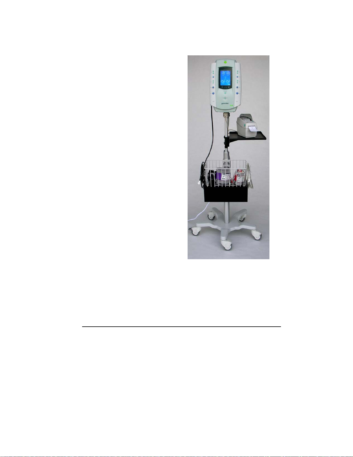
The SmartPump is shown with the recommended Stryker roll stand and cuff basket. The optional
printer, printer tray and power cord organizer mounted below the basket are also shown.
Control Panel and Display 8
Page 9

Features
Convenient Preparation
♦ The internal battery is charged automatically whenever the SmartPump is plugged into
an AC power source. The internal battery is recharged to approximately 80% level within
one hour.
♦ The fully charged internal battery provides five hours of uninterrupted power. However,
internal battery power is a safety feature and is to be used as a back up only. Always
connect the SmartPump to an AC power source for normal operation.
♦ Battery ‘saver’ technology keeps the internal battery charged. If the SmartPump is fully
charged, then left ‘OFF(standby)’ and unplugged, the internal battery is kept charged for
up to 30 days.
♦ The SmartPump is center mounted to its recommended Stryker roll stand with pole.
♦ Fill lines are attached to the positive locking connectors located at the bottom corners of
the SmartPump.
♦ At start-up, the SmartPump performs a self-test automatically and tests the pneumatic,
pressure, display, battery, and processor systems. The SmartPump will alert the user via
alarms, indicators and the display of error codes to assist in troubleshooting.
Ease of Operation
♦ The procedure timer and cuff target pressure may be set using simple, intuitive steps.
Control buttons are clearly identified.
♦ Inflation is initiated by pressing the Inflate button.
♦ Deflation is initiated by pressing and holding the Deflate button for 1.5 seconds.
Continuous, Real-time Monitoring
♦ The large, bright, backlit LCD display shows total elapsed cuff inflation time and cuff
pressure (mmHg). The displayed time format is user selectable: minutes or hours and
minutes.
♦ Audible control alarms and flashing graphical symbols identify conditions requiring
attention.
Accessory Information*
Description REF
Roll Stand with Pole …..…….………………………….…………..5920-013-000
Tubing, Stockinettes, Fill Lines, and Adapters .………………..5920-xxx-xxx Series
Disposable Tourniquet Cuffs ………………………..….…………5921-xxx-xxx Series
Non-sterile Reusable Tourniquet Cuffs…..…………….………..5922-xxx-xxx Series
*Contact your Stryker sales representative for a complete list of accessories.
Control Panel and Display 9
Page 10

Power Options
AC Power
The Smart Pump’s primary power source is AC power. As a safety
feature, the SmartPump’s internal battery provides an alterative (back
up) power source if AC power is lost.
Always connect the SmartPump to an AC power source for normal
operation.
Internal Battery
The SmartPump’s internal battery automatically provides back-up
power if AC power is interrupted. The internal battery when fully
charged supports up to five hours of operation.
If, at initial start-up, the SmartPump is not plugged into AC power, the
following occurs:
♦ no AC is displayed on the lower left of the LCD.
♦ The Alarm Indicator Mute button flashes red.
Pressing the Alarm Indicator Mute button within 30 seconds of initial
start-up will cancel the alarm. In this mode, the Alarm Indicator Mute
button will return to green, the no AC indicator will remain illuminated
and the battery symbol will indicate the amount of battery charge.
NOTE: If, at initial start-up, there is no AC present and the Alarm
Indicator Mute button is not pressed within 30 seconds, the
SmartPump will return to its ‘OFF(standby)’ mode automatically. This
feature prevents the SmartPump from unintentionally being used in a
(back up) battery mode and prevents accidental battery discharge
during transport and storage.
If AC power is interrupted during normal use, the SmartPump will use
its internal battery automatically. Press the Alarm Indicator Mute
button to acknowledge the change in power source. The Alarm
Indicator Mute button returns to green.
When AC power is restored, the SmartPump will return to its normal
AC operation automatically.
When the SmartPump is unplugged and turned ‘OFF(standby),’ it
conserves its internal battery automatically using a power conservation
mode. If fully charged, the internal battery is kept charged for up to
750 hours.
Control Panel and Display 10
Page 11

Low Battery Power Alarms
If a ‘low battery’ alarm condition occurs, connect the SmartPump to AC
power as soon as possible. If AC power is unavailable and the internal
battery becomes fully discharged, the SmartPump will maintain cuff
pressure. Manual cuff deflation is required.
• If 30 minutes of internal battery operating time remain, the
following will occur: an audible alarm, the Alarm Indicator Mute
button will flash red and the battery charge icon will blink. The
alarm may be muted for 15 minutes.
• If 15 minutes of internal battery operating time remain, an audible
alarm will occur. The alarm may be muted for one minute,
indicating the battery is ‘minutes’ from full discharge.
Maintaining Internal Battery Charge
When the SmartPump is plugged into AC power, its internal battery is
charging automatically.
The SmartPump control panel indicates battery-charging status as
follows:
Battery Charging Symbol: The segments of this symbol illuminates sequentially
and repetitively while the internal battery is being charged. This occurs when the
SmartPump is connected to an AC power source. Once the internal battery is
fully charged, all of the segments are lit.
Battery Power Symbol: The segments of the battery power symbol are lit to
indicate the level of battery charge during internal battery operation. For
example, three segments lit indicate a charge level of approximately 80%.
AC Power LED Indicator: Illuminated green whenever AC power is applied to the
unit.
Battery Charge LED Indicator: Indicates battery charge status. The indicator
operates when connected to AC power and the SmartPump is on or off.
♦ Green (steady): internal battery is fully charged, in trickle or slow charge
mode.
♦ Yellow (blink): internal battery is in fast charge mode and may require one
hour to reach an 80% charge level.
♦ No Light: internal battery is not charging; AC power may not be present. if
AC power is present, there may be battery charge circuit failure or internal
battery failure.
Control Panel and Display 11
Page 12
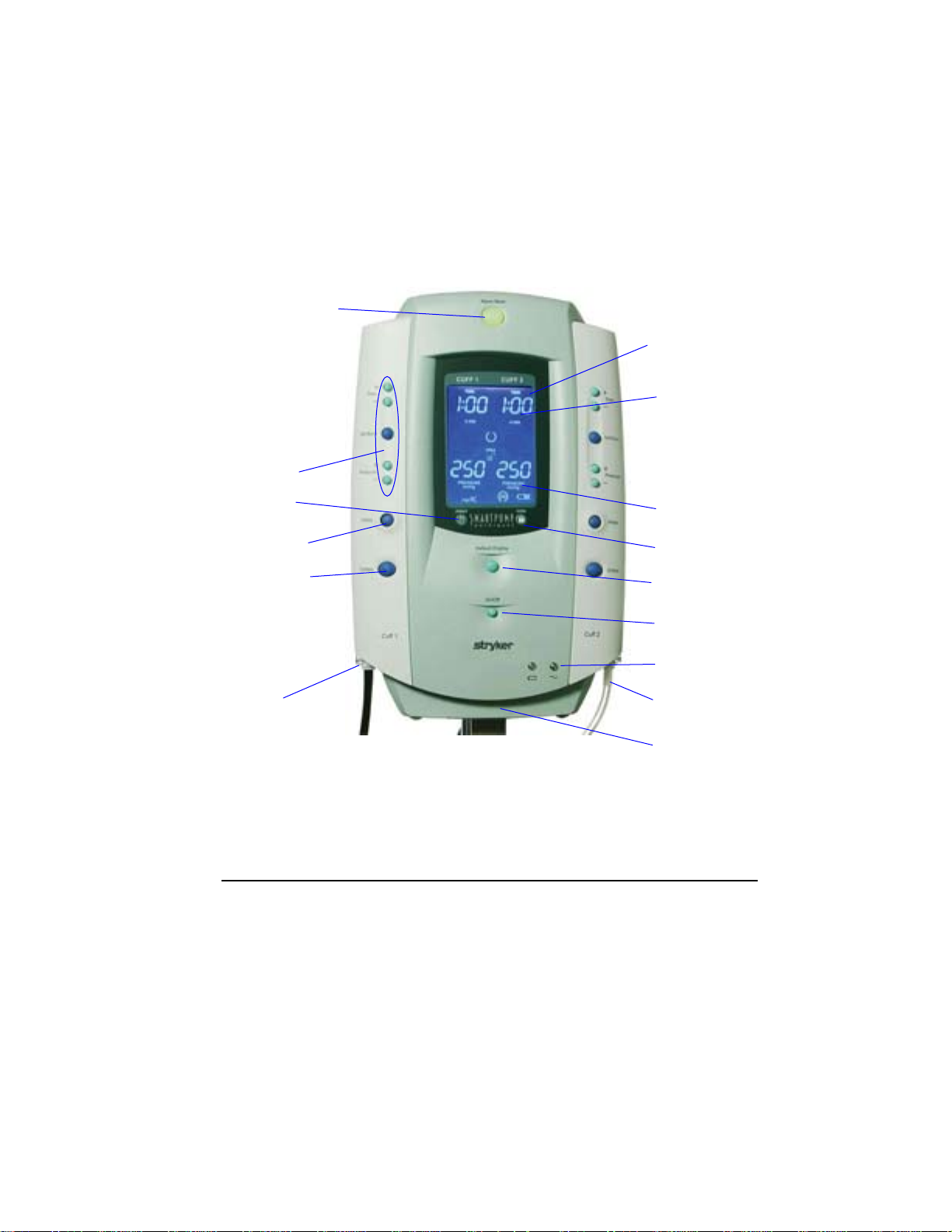
2 Control Panel and Display
This section reviews the SmartPump’s interfaces, control panel layout,
display screen functions, and icons.
The control panel is the user’s interface to control, adjust, and set the
following: Procedure Timer and Cuff Pressure, Inflation, Deflation, and
Default Display. Cuff pressure and elapsed cuff time are displayed in
real-time.
Alarm Indicator
Mute button
Cuff Control
Buttons
Time and
Pressure
Adjustments
Print Button
Inflate Button
Deflate Button
Cuff 1 Cuff 2
Fill line Fill line
Connector Connector
LCD
Display Screen
Time display:
User Selectable:
Minutes or
Hours and Minutes
Pressure display:
mmHg
IVRA Lock
Default Display
button
Cuff I
Cuff 2
On/Off (standby)
AC and Battery
Indicators
Serial Interface
Port (not shown)
Control Panel and Display 12
Page 13

Control Buttons
Button Explanation
♦ Turn ON by pressing, then releasing the ON/OFF (standby)
button.
♦ Turn OFF by pressing and holding the ON/OFF (standby)
button for 1.5 seconds (safety pause).
WARNING: Turning OFF the SmartPump while cuffs are inflated
will deflate the cuffs and total elapsed time information will be
lost.
SET/SAVE
1. Press the Set/Save button to initiate a change of the
SET/SAVE
+
TIME
-
+
PRESSURE
-
INFLATE
and/or target
blink after the Set/Save button is pressed.
2. Press the Set/Save button again to save new time or pressure
values.
T
IME Increase/Decrease (located above the Set/Save button)
After pressing the Set/Save button, press these buttons to
increase (+) or decrease (-) the inflation time for the selected
cuff. Each button press changes the time value in 5-minute
increments (1-minute increments within the 1 to 15 minute time
range). The numeric display changes accordingly.
P
RESSURE Increase/Decrease (located below the Set/Save button)
After pressing Set/Save button, press these buttons to increase
(+) or decrease (-) the inflation pressure for the selected cuff.
Each button press changes the pressure value in 5 mmHg
increments. The numeric display changes accordingly.
I
NFLATE
Press the
cuff to its target pressure. If a cuff is deflated during a procedure,
press the Inflate button to return to the set pressure. The Timer
stops during the period of a deflation and resumes accumulating
total ‘cuff time’ upon reinflation.
TIME
PRESSURE for the corresponding cuff. The display will
INFLATE button of the corresponding cuff to inflate the
Control Panel and Display 13
Page 14

DEFLATE
INFLATE
DEFAULT
DISPLAY
Press and hold the Deflate button for 1.5 seconds (safety pause)
to initiate deflation. When deflation begins and after it is
completed, the Deflation icon appears next to the cuff pressure
gauge.
The tourniquet time monitor will stop accumulating time and
display the total inflated ‘cuff time.’
OTE: To interrupt a deflation instantly, press the Inflate button.
N
Re-inflation will commence immediately. The timer is restarted to
accumulate additional elapsed ‘cuff time.’
At the end of a procedure and after deflation has occurred, press
the Default Display button to clear and reset the SmartPump to its
default time and pressure settings.
The Default Display button is also used to set new default time
and pressure settings for preferred practice settings. See
Changing Default Time and Pressure Settings.
LARM INDICATOR MUTE BUTTON
A
Indicator button illuminates green when the SmartPump is
operating normally.
Indicator button flashes red when the SmartPump is in an alarm
condition. Press the Alarm Indicator Mute button to mute the
audible alarm. Correct the alarm condition to restore the indicator
button to green.
Control Panel and Display 14
Page 15
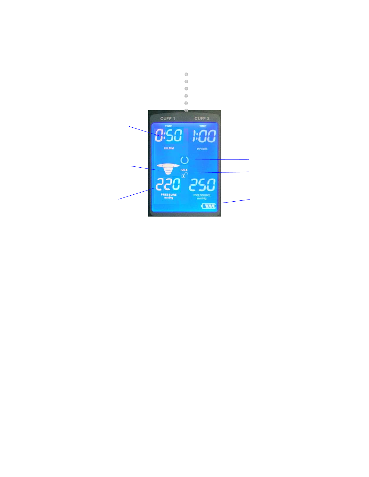
Display Screen
Areas of the SmartPump display screen are illustrated below.
Inflation Timer:
Indicating elapsed
time: 50 minutes
(Time displayed in
hours and minutes
format)
Pressure Gauge:
Indicating cuff at
target pressure
Actual Cuff
Pressure
220 mmHg
See Display Indicators.
Active Cuff
Cuff 1
Ready Cuff
Cuff 2
Default Settings:
Time: 1 hour
Pressure: 250 mmHg
System Ready
Indicator
IVRA Lock
Status: Unlocked
Battery Charge
Indicator
Control Panel and Display 15
Page 16

Display Indicators
Status Indicators
Default Display: Illuminated when the time and pressure are set for
the default target values.
Ready: All components are functioning normally and the unit is ready
to use.
Battery Charge Status: Indicates if battery is charging (bars light
sequentially) or battery charge level (when running from battery).
IVRA Lock: Indicates whether IVRA is locked or unlocked. This control
provides accidental cuff/bladder deflation protection.
H: MM or MINUTES: Indicates time format in use.
Deflation: Indicates corresponding cuff is deflating or deflated.
Alarm Indicators
Service Required: When the SmartPump detects a condition that
requires service, a service code with a wrench is displayed on the LCD
and an audible alarm will occur. Note the code and call Stryker for
assistance: 1-800-253-3210.
Caution: When an alarm is detected, the ‘Alert’ triangle is displayed,
and either the time or pressure value will blink. DO NOT proceed until
the alarm condition is resolved. Failure to comply may result in patient
injury.
Control Panel and Display 16
Audible Alarm: Indicates when the SmartPump is in an alarm
condition and the audible alarm has been triggered.
Alarm Muted: Indicates when the SmartPump is in an alarm condition
and the audible alarm has been muted.
Page 17
3 Preparing for Use
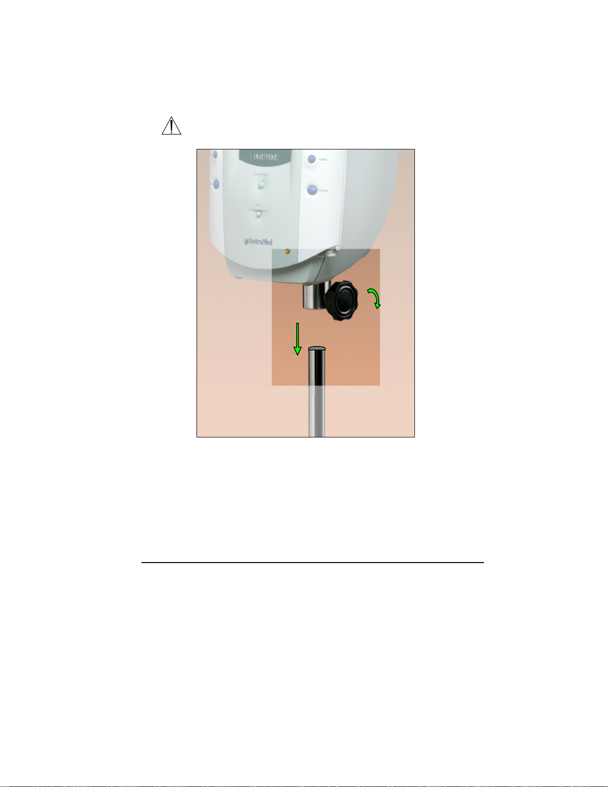
Mounting the SmartPump
WARNING: Ensure the SmartPump is mounted on the roll stand pole
securely. Failure to comply may result in user/patient injury.
Cuff 2
Roll Stand Pole
1. Assemble roll stand. See instructions for use supplied with roll
stand.
2. Gently lower the SmartPump onto the roll stand pole. Adjust the
height of the SmartPump using the adjustment knob to facilitate
access to the display and controls.
3. Tighten the knob to secure the SmartPump to the roll stand pole.
Preparing for Use 17
Page 18

Power Requirements
The hospital-grade power cord shipped with the SmartPump is UL
listed and configured for North American power sources. The
SmartPump is configured for use with 120V, 10A, 60 Hz AC power.
Initial Set-up
The SmartPump is shipped with a fully charged battery, which provides
a safety back up power source.
1. Mount the SmartPump onto the roll stand with pole.
WARNING: DO NOT connect any other electrical device into the
power receptacle of the power cord organizer, except the SmartPump
and Tourniquet Report Printer. Failure to comply may result in
user/patient injury.
2. Connect the power cord between the SmartPump and the power
cord organizer with power receptacle or a hospital-grade AC
receptacle.
Press and release the ON/OFF (standby) button to initiate system
power on and self-test. The self-test checks the pneumatic system,
pressure, display, battery, and processors. Self-test errors are reported
via service codes on the LCD display. See Service Code Summary
section.
Upon successful completion of the system self-test, including battery
charge level voltage test, the Ready indicator appears in the center of
the display.
The Battery Charging indicator on the bottom right corner of the front
enclosure indicates battery charge status. The system automatically
begins charging the battery whenever it is connected to AC power.
The Battery Charge indicator segments on the lower right of the LCD
illuminate sequentially when the battery is charging.
If the battery is not charged adequately, the alarm sounds and the
Battery charge icon indicates low charge level.
Press and hold the ON/OFF (standby) button for 1.5 seconds to turn
the unit off. Allow more charging time.
NOTE: The NiMH battery will attain approximately 80% of its rated capacity
within one hour of charging.
Preparing for Use 18
Page 19

Default Parameters
SmartPump factory preset default time and pressure settings are:
1. Elapsed Procedure Time: One hour
(Displayed as:
2. Target Cuff Pressure: 250 mmHg
(Displayed as:
Procedure Timer
The timer display shows elapsed procedure time.
The timer may be set to the desired cuff inflation time from a minimum
of one minute. Timer adjustment may be made in one-minute
increments from 1 to 15 minutes, and five minute increments from 15
to 240 minutes.
The Cuff time alarm is preset at the factory for one hour. This means
that, if unchanged, the time setting for the Cuff is one hour. The
Timer’s alert will sound, the Alarm Indicator Mute button will flash red
and the corresponding time display will flash when the preset total
elapsed inflated cuff time has been reached.
OTE: The SmartPump does NOT automatically deflate the cuff when
N
the target time is reached. It maintains inflation until the Deflate button
is pressed or the SmartPump is turned off.
1:00)
250)
Target Pressure
The default target pressure is preset to 250 mmHg at the factory. The
default pressure may be adjusted and set between an operating range
of 100 to 475 mmHg, in 5 mmHg increments.
Preparing for Use 19
Page 20

Changing Default Time and Pressure Settings
To change the Default Time and/or Target Pressure:
1. If the unit is turned off, press the ON/OFF (standby) button to
turn it on. Following self-test, it will enter the ‘Ready’ state.
2. Press the Set/Save button on the side requiring change.
The corresponding time and pressure values will blink.
3. To change the default time, use the increase (+) or decrease (-)
buttons. Each press adjusts the time in 5-minute increments
(one-minute increments in the 1 to 15 minute time range). The
numeric time display changes accordingly.
4. To change the default pressure, use the increase (+) or
decrease (-) buttons. Each press adjusts the pressure in 5
mmHg increments, numeric pressure values change accordingly.
5. When the desired values are displayed, press the Default
Display button to store the new values as the new default
settings. The display stops blinking and the double-beep
indicates the new values have been stored.
The Ready indicator reappears in the center of the display.
The Default Display indicator appears near the bottom of the display
indicating that the default settings are being used.
OTE: If the Default Display button is not pressed within five minutes
N
of starting the adjustment process, the Set Mode is cancelled without
changing the settings.
Preparing for Use 20
Page 21

r
r
4 General Use Procedure
The basic steps required to initiate the inflation and deflation of a
tourniquet cuff are summarized below:
OTE: Prior to cuff inflation, the slight impeding affect caused by the
N
presence of the un-inflated cuff and limb protection sleeve may inhibit
venous return, causing slight intraoperative bleeding at the beginning of
the procedure.
1. Turn unit on
2. Confirm default settings are correct or,
3. Set procedure timer and target cuff pressure
4. Position cuff on patient’s limb
5. Connect cuff to fill line connector
6. When ready, press the Inflate button
7. Monitor cuff time and pressure during the procedure
8. Manage Timer and Pressure as necessary
9. Deflate the cuff and disconnect the cuff from fill line connector.
WARNING: At the end of a procedure, as soon as the tourniquet
pressure is released, remove the cuff, sleeve and other underlying
materials, as the slightest impedance of venous return may lead to
congestion and pooling of blood in the operative field. Failure to
comply may result in patient injury.
Connect the Cuff To Fill Line Connector
The cuffs are controlled by the
Fill Line
Connecto
Fill Line
Connecto
corresponding sides of the SmartPump
control panel.
Quick connect style fill line connectors are
located on the bottom corners on the front of
the SmartPump.
General Use Procedure 21
Page 22

Turn On the SmartPump
Press the ON/OFF (standby) button to activate the SmartPump and
initiate the self-test.
1.10) appears briefly at the bottom left
button.
1.10
The software version (example:
of the display.
At the conclusion of a successful, self-test:
The default time and pressure values for both cuffs are displayed.
The Ready indicator appears in the center of the display.
The Default Display icon appears at the bottom of the display.
If the displayed Time and Cuff Pressure settings are acceptable,
proceed with the cuff inflation by pressing the Inflate
WARNING indicators will appear on both sides of the display and a
General Use Procedure 22
If the self-test fails, the following occurs:
The Alarm Indicator Mute Button flashes red and the audible alarm
sounds. Press the Alarm Indicator Mute Button to mute the unit.
“wrench” icon will appear next to the service code, indicating service
is required. DO NOT proceed until you resolve the alarm condition.
Failure to comply may result in patient injury.
Note the code and call Stryker for assistance: 1-800-253-3210.
Page 23

Setting Timer and Target Pressure
To adjust the cuff inflation timer or the target pressure, follow the
instructions below. Newly set values will remain in effect until they are:
(1) changed, (2) the Default Display button is pressed after deflation
or, (3) the unit is turned off and restarted.
NOTE: A quick error-beep sounds if an inappropriate button press
sequence is used. For example, if the (+) or (-) button is pressed
before pressing Set/Save, the unit produces an error-beep.
1. Time and Pressure values may be changed when the
SmartPump is in the ‘Ready’ mode or during active cuff inflation.
2. Press the Set/Save button on the side requiring change.
The corresponding Time and Pressure values will blink.
7. When using two cuffs, the cuffs are controlled separately.
3. To change the set Time, use the increase (+) or decrease (-)
buttons. Each press adjusts the time in 5-minute increments (1minute increments in the 1 to 15 minute time range). The
numeric time display changes accordingly.
4. To change the set Pressure, use the increase (+) or decrease (-)
buttons. Each button press adjusts the pressure in 5-mmHg
increments, displayed numeric values change accordingly.
5. When the desired value is displayed, press the Set/Save button
to implement the new settings. A confirmation double-beep
indicates the new values are accepted. The blinking display
returns to normal operation.
6. If a cuff is not inflated, the Ready indicator reappears in the
center of the display screen. If settings are changed while a cuff
is in use, the cuff Pressure and/or Time changes are real-time.
General Use Procedure 23
Page 24

Time Display Format
Change the Time Display format by pressing both Time (+) buttons
simultaneously while the SmartPump is in the ‘ready’ mode, with both
cuffs deflated (not active). It is not possible to change the time
format if a procedure is started.
If it is currently displaying H: MM (hours and minutes) it will
automatically shift to Minutes and vice versa.
A Time Display format change remains in effect permanently until
changed again.
Alarm Volume Adjustment
While pressing the Alarm Indicator Mute Button, press either the (+) or (-) buttons on
the top left of the SmartPump to increase or decrease the alarm volume to a desired
level. Alarm volume may be changed when the SmartPump is active or in the ‘ready’
mode.
General Use Procedure 24
Page 25

Default Display Viewing Preferences
The SmartPump is preset to display each cuff default time and pressure
setting continuously while in the ‘ready’ mode. When a single cuff is inflated,
the other cuff’s default settings remain displayed.
In a clinical environment, where single cuff procedures are predominant, the
user may choose to ‘minimize’ the display of the unused cuff’s default
settings, as illustrated in figure B.
To minimize the Default Display, perform the following:
(1) With the SmartPump in the ‘ready’ mode (no cuffs inflated), press
and hold the Alarm Indicator Mute button, then press the Default
Display button. See figure A.
(2) The display will cycle twice, blinking one side, then the other. This
confirms the selection of minimization. In this mode, when either
cuff is inflated, the unused cuff’s default settings will be minimized.
See figure B.
(3) When in the ‘Default Display Minimization Mode’, minimized default
settings may be viewed by:
a. Pressing the Default Display button, or
b. Locking the IVRA Lock, or
c. Pressing the Inflate button on the minimized side.
To restore the continuous display of the default settings, repeat step 1
above. The entire display will blink indicating the change in mode.
General Use Procedure 25
Figure A
Figure B
Page 26

Setting Time and Date
The SmartPump’s real-time clock tracks Time and Date. Time/Date is
maintained by its internal battery.
NOTE: The real-time clock does not automatically adjust for daylight
savings time changes.
To adjust Time and Date, the SmartPump must be in the ‘ready’ mode
without an inflated cuff. It is not possible to change the Time or Date if
a procedure is underway.
Button Explanation
1. Confirm the SmartPump is in the ‘ready’ mode.
2. Simultaneously press and hold Set/Save and + Time buttons
on the left side of the SmartPump for four seconds. Release
both buttons. The current time value (HH: MM, 24 hour
format) will appear in the bottom left corner of the LCD, with
the hours value blinking.
For example, the hour’s value is 12 (noon) (time is in 24-hour format).
12:34
General Use Procedure 26
Page 27

4. Press Set/Save button to save the new hours setting. The
3. Set the hours: Use the left side time increase (+) or
decrease (-) buttons to adjust the hours setting.
minutes will blink. For example, the minute’s value is 34.
12:34
5. Adjust minutes: Use the left side time increase (+) or
decrease (-) buttons to adjust the minutes setting.
6. Press the Set/Save button to save the new minutes setting.
The current calendar date will appear, with the month
blinking, i.e., 12 (December).
7. Set the month: Use the left side time increase (+) or
decrease (-) buttons to set the month.
8. Press Set/Save to save the new month setting. The current
calendar date will blink, i.e., the date is the 6th.
9. Set calendar date: Use the left side time increase (+) or
decrease (-) buttons to set the date.
10. Press Set/Save to save the new date setting. The current
calendar year will blink. For example, the year is
12.06
12.06
2006
General Use Procedure 27
11. Set the year: Use the left side time increase (+) or
decrease (-) buttons to set the year.
12. Press Set/Save to save the new time and date settings. The
SmartPump will now return to the ‘default display’ mode.
Page 28

Cuff Inflation
The individual channels for Cuff 1 and Cuff 2 operate independently. The
SmartPump display screen displays real-time pressure values and total
elapsed cuff inflation time for each cuff.
Intravenous Regional Anesthesia (IVRA) Lock
The Intravenous Regional Anesthesia (IVRA) Lock may be activated either
prior to or after inflation. The lock prevents accidental deflation of an
active cuff associated with a Bier Block procedure or the management of
two cuffs involved in a bi-lateral procedure.
In its unlocked state, the IVRA Lock icon resembles an unlocked padlock.
In a locked state, the icon changes to a locked padlock. See images
below:
The IVRA (lock, unlock) button is below the LCD, on the right.
If, when attempting to deflate the second cuff with the IVRA Lock enabled,
the SmartPump will produce an audible error-beep and the IVRA padlock
will blink.
IVRA
Lock Button
To Inflate a Cuff
Press the Inflate button on the selected side.
♦ The selected cuff is inflated to the target pressure.
♦ The SmartPump begins tracking and displaying the elapsed cuff time.
The elapsed time appears at the top of the screen and is represented
numerically and graphically.
♦ The cuff pressure is monitored on a real-time basis. The pressure is
displayed numerically at the bottom of the screen.
♦ The graphic pressure gauge appears above the numeric pressure and
graphically represents the status of the cuff.
General Use Procedure 28
Page 29
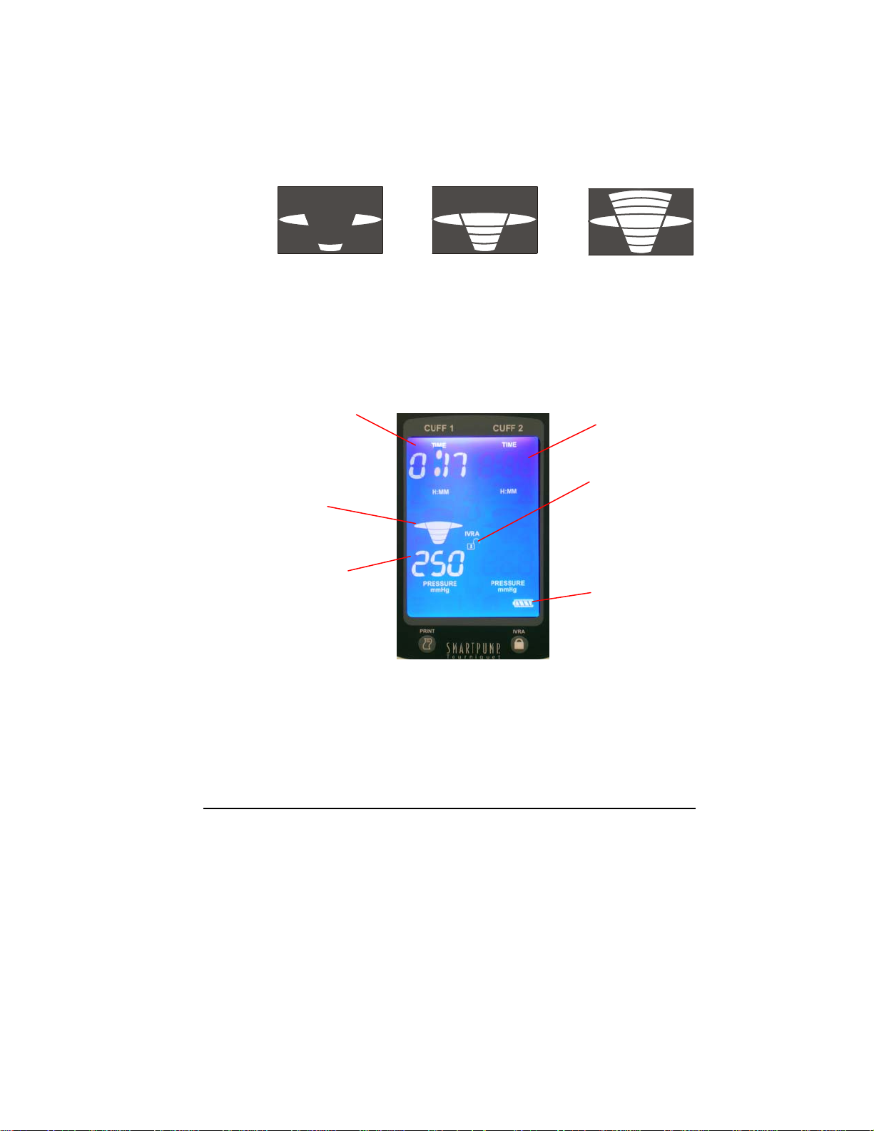
Cuff Pressure Gauge
The pressure gauge displays the actual pressure in relation to the target
pressure. Target pressure has been reached when the wide oval
“mushroom” in the center of the gauge is illuminated. Pressure gauge
illustrations below depict various states of target pressure.
Under Target Target Pressure Over Target
Monitor Time and Pressure
The SmartPump display screen provides the information needed to monitor
the elapsed procedure time and the inflation pressure of the cuff(s) in use.
Active Ready
Inflation Time
(H:MM format)
Indicating
elapsed
inflation time of
17 minutes
Pressure
Gauge
Indicating cuff is
at target
pressure
Actual Cuff
Pressure
(mmHg)
Cuff Cuff
Default Display
in minimization mode
(see Default Display
Viewing Preferences)
IVRA Lock
Indicating the
IVRA lock is
unlocked
Battery Status
Time and/or pressure settings may be changed during a procedure.
Immediately after changing the setting(s) and pressing the Set/Save
button, the SmartPump adjusts the time and/or pressure to the new
setting(s). See Setting Timer and Cuff Pressure.
General Use Procedure 29
Page 30

When the Target Time Is Reached
Once the inflation timer has reached the target time set for the procedure,
the following happens:
1. The Alarm Indicator Mute button flashes red, the ‘Time’
When the target time is reached, do one of the following:
♦ Deflate the cuff by pressing the Deflate button for 1.5 seconds,
♦ Press the Alarm Indicator Mute button to mute the alarm for 15
setting on the LCD blinks once per second and an audible
alarm chimes 6 times – over 6 seconds. The audible chime
then pauses 6 seconds and repeats the 6-beep sequence.
2. The alarm chime will continue indefinitely until (a) the Alarm
Indicator Mute button is pressed, (b) additional time is added
to the timer or (c) the cuff is deflated.
3. When the Alarm Indicator Mute button is pressed, the
audible chime is silenced for 15 minutes. However, the time
value on the LCD display will continue to blink once per
second.
and if necessary, re-inflate the cuff.
minutes. The Alarm light will continue to flash red. The
SmartPump will continue to record and display the total elapsed
cuff time.
♦ Add more time using the Set/Save button and (+) button. See
Setting Timer Cuff Pressure.
OTE: The SmartPump does not automatically deflate when the target time is
N
reached. Deflation must be initiated by pressing the Deflate button.
General Use Procedure 30
Page 31

Real-time Pressure Management and Alarms
The SmartPump maintains real-time cuff pressure within its normal operating
parameters relative to the set target pressure automatically. Pressure variances are
typically detected and corrected to the target pressure instantaneously, within
two/tenths of a second.
Its pressure adjustment responses are sequenced to deliver optimal, progressive
pressure compensation without causing overpressure fluctuations, unnecessary frequent pressure adjustments or triggering false, transient pressure alarms. This
enhances overall cuff pressure maintenance, while addressing the unique pressure
dynamics associated with various size cuffs and their relatively low inflatable
volumes.
After initial cuff inflation, the SmartPump compensates for minor changes in cuff
pressure above or below the set target pressure automatically. Cuff pressure
changes, within normal operating parameters and pressure compensation
thresholds, may be caused by:
(a) Limb extension and contraction,
(b) Initial cuff conformity and tissue compression
(c) A leaking/damaged reusable cuff, leaking cuff O-ring, loose Luer connector,
or fill line leak.
Intraoperative limb manipulation may cause the cuff to induce a momentarily, minor
high and/or low-pressure fluctuation that the system detects and corrects
automatically.
A momentary decrease in limb volume, associated with extension motions may
cause the pneumatic system to sense low pressure, as the cuff’s compressible
target has become briefly ‘smaller.’ This type of minor, low-pressure activity is
corrected precisely by the SmartPump’s internal pressure reservoirs.
Momentary increases in pressure within the pneumatic circuit may also occur due to
external compression of the cuff during limb contraction, which temporarily causes
the limb to assume a ‘larger’ compressible volume. This type of momentary highpressure is managed automatically and adjusted to target pressure instantaneously.
General Use Procedure 31
Page 32

WARNING: Cuff and fill line leaks may cause regular, frequent cycling of valves
accompanied by repeated or continuous pump motor activity refilling the internal
pressure reservoir. This type of leak becomes problematic if the leak volume
increases during the procedure, creating a leak rate, which cannot be compensated
for by the SmartPump’s maximum flow rate. Discard damaged reusable cuffs,
replace damaged cuff O-rings and fill lines and use new, single use disposable
cuffs. Failure to comply may result in patient injury.
Cuff pressure conditions which exceed those associated with normal operation and
the responses reviewed previously, will trigger the SmartPump’s audible alarm and
visual alarms including the flashing red Alarm Indicator Mute button and blinking
cuff pressure value(s). The SmartPump will continue to adjust pressure to the set
target pressure while the audible alarm is muted. In a muted state, the pressure
values continue to blink.
If automatic pressure adjustments do not resolve the low or high-pressure
conditions within one second, the following occurs:
♦ The cuff pressure audible alarm sounds once a second.
♦ Low-pressure alarms are muted for 30 seconds by pressing the
Alarm Indicator Mute button, with the exception of a minor lowpressure event.
♦ A minor low-pressure alarm is muted for 60 seconds. Minor low
pressure is defined as a pressure value not more than 25 mmHg
below target, for a period longer than one second.
♦ The Alarm Indicator Mute button will continue to flash red when
the audible alarm is muted.
♦ Icons associated with the alarm condition will continue to blink
until the condition is corrected.
When the correct pressure is restored, within tolerance, at the set target pressure,
the alarm state is cleared automatically.
General Use Procedure 32
Page 33

Cuff Deflation
A cuff may be deflated at any time during a procedure.
To deflate a cuff:
♦ Press the Deflate button for the selected cuff for 1.5 seconds.
As the cuff deflates, the following happens:
♦ The numeric pressure and gauge indicate a real-time pressure
decrease. When the cuff pressure reaches zero, the numeric
pressure display and the pressure gauge become blank.
♦ The Deflation indicator appears next to the pressure value on the
relevant side of the display.
In its deflated (inactive) state, the SmartPump continues to monitor ambient
air pressure. The SmartPump exhausts any ambient pressure that may be
caused by cuff or patient movement automatically, prior to cuff removal.
WARNING: At the end of a procedure, as soon as the tourniquet cuff
pressure is released, remove the cuff, sleeve and other underlying
materials. The slightest impedance of venous return may lead to
congestion and pooling of blood in the operative field. Failure to
comply may result in patient injury.
The total elapsed cuff time remains displayed.
Prior to pressing the Default Display button, a deflated cuff may be reinflated to the highest pressure used during the procedure by pressing the
Inflate button. The Timer will restart and continue to accumulate inflated
cuff time.
The most recent procedure’s cuff time is cleared when the Default
Display button is pressed.
NOTE: The IVRA Lock may be used to prevent accidental cuff deflation during
Bier Block procedures. See Intravenous Regional Anesthesia (IVRA) Lock
and Bier Block Procedure.
General Use Procedure 33
Page 34

Tourniquet Report Printer
When connected to the optional SmartPump Tourniquet Report Printer, the
SmartPump has the ability to print a tourniquet report, providing a summary
of tourniquet activity.
This 2-inch by 3-inch report is printed on a self-adhesive label that easily
attaches to the patient chart.
To print the report, press the Print button located below the LCD display
on the unit’s left side.
Procedure summary data is saved to a non-volatile memory that will preserve
the data even if the SmartPump is turned off, AC power is removed or the
internal battery is fully discharged.
Each time the SmartPump starts a new procedure, the previous procedure is
fully erased and new data is accumulated.
Procedure summary data is preserved until either of the following events
happen, which will cause the last procedure’s summary data to be erased:
Default Display button is pressed and the Inflate button is pressed
-- or --
SmartPump is powered down, then restarted and the Inflate button is pressed.
See instructions for use supplied with the SmartPump Tourniquet Report Printer.
General Use Procedure 34
Page 35

Bier Block Procedure
Follow your institution’s standard Bier Block procedures.
WARNING: During a Bier Block or dual cuff procedure, confirm
the status of the primary cuff before initiating a deflation. Failure
to comply may result in patient injury.
The SmartPump will support a Bier Block cuff with its (Cuff 1) and
(Cuff 2) tourniquet controls.
♦ Use of the IVRA Lock prevents accidental deflation of a cuff.
♦ To engage the IVRA Lock, press the IVRA Lock button. The
IVRA padlock icon will change to the locked position.
1. Begin the procedure by sequencing the inflation and deflation of the
Bier block cuffs according to your institution’s standard practice.
2. When the procedure is completed, unlock the IVRA Lock to deflate the
remaining Bier cuff,
3. Reduce the cuff pressure in stages. Follow standard Set/Save
pressure adjustment steps. See Setting Timer and Cuff Pressure.
4. When the incremental deflation sequence is complete, unlock the
IVRA Lock and fully deflate the cuff.
or
OTE: Press the Inflate button to interrupt a cuff deflation instantly or to
N
return a cuff to the highest pressure used during the preceding procedure.
General Use Procedure 35
Page 36

Responding to Alarms and Service Codes
When an Alarm event occurs, the following happens:
♦ The Alarm Indicator Mute button flashes red.
♦ An audible alarm sounds.
♦ The associated graphic or numeric will flash.
♦ When the target procedure time has been reached, the time
display blinks.
Press the Alarm Indicator Mute button to silence the alarm. The audible
Time alarm will remain muted for 15 minutes. Pressure alarms may be
muted for 30 seconds or one minute depending on their severity.
Once the alarm is muted, the audible Alarm indicator is illuminated
with a slash.
Correcting the alarm condition will reset the alarm system automatically.
Common alarms are typically corrected by:
(a) eliminating a leaking pneumatic connection or replacing a leaking cuff,
(b) adding time to the procedure Timer,
(c) charging a low battery, or
(d) connecting the SmartPump to an AC power source.
Service Codes
Service codes are listed in the Service Code Summary section. When
the SmartPump detects a condition that requires service, a service
code with a wrench is displayed and the SmartPump will alarm. Note
the code and call Stryker for support at 1-800-253-3210.
General Use Procedure 36
Page 37

Using the SmartPump’s Backup Capability
Should one side (Cuff 1 or Cuff 2) become inoperative, the user may
switch sides and continue operation.
The following steps summarize the techniques used to ‘switch’ a cuff from
one side of the tourniquet pump to the other as ‘backup’ when an inflated
(active) cuff is at risk and no alternative is available. This procedure should
be used only when necessary. Adapt these guidelines to reflect your
institution’s protocols.
Prior to action, confirm all connections and cuffs are leak-free.
SINGLE TOURNIQUET CUFF
♦ During the initial inflation, if the tourniquet cuff cannot reach or maintain
target cuff pressure, discontinue use.
♦ After inflation, if cuff pressure is at risk and/or tourniquet pump alarms
cannot be resolved:
1) Clamp-off the inflated cuff’s fill line and remove it from the fill line
connector of the SmartPump.
2) Press the Deflate button on the failed side to clear its alarm state.
3) Move the clamped fill line cuff to the other side of the SmartPump
and insert it into the fill line connector.
4) Press the Inflate button and release the clamp as the SmartPump
takes control. This action may cause a momentary pressure alarm.
5) Adjust the pressure and cuff timer as necessary.
General Use Procedure 37
Page 38

Bier Block Cuff
WARNING: In the unlikely event of a complete SmartPump failure, such
as the simultaneous loss of AC and battery power, the SmartPump is
designed to close and lock its internal valves to protect an inflated cuff
from unintended deflation. Deflate by manually disconnecting the cuff.
Failure to comply may result in patient injury.
♦ During initial inflation, if the primary cuff cannot reach or maintain target
pressure prior to anesthetic injection, discontinue use of the cuff.
♦ If, prior to deflation of the primary cuff, the second cuff cannot reach or
maintain target pressure, do the following:
1. Clamp-off the primary cuff to retain pressure, and disconnect the
fill line. This action will cause the SmartPump to alarm.
2. Connect the second cuff’s fill line to the fill line connector of the
primary cuff.
3. The SmartPump will inflate the second cuff to the target pressure.
4. After confirming the second cuff is at the target pressure, the
clamped primary cuff may be released.
5. Adjust the Pressure and Cuff Timer as necessary.
General Use Procedure 38
Page 39

5 Cleaning and Maintenance
Cleaning Recommendations
Clean the SmartPump periodically using the following procedure:
CAUTIONS:
• DO NOT sterilize the SmartPump by any means including
EtO, chemical disinfectant, or steam. Failure to comply may
result in product damage.
• DO NOT use chlorine, ammonia, or iodine-based agents.
Failure to comply may result in product damage.
• DO NOT allow water, detergent or any liquid to enter any
button opening or electrical connector. Failure to comply may
result in product damage.
• DO NOT use abrasive materials. Failure to comply may result
in product damage, like scratching the LCD window.
1. Wipe the exterior surfaces with a soft cloth moistened with a
mild detergent to clean the SmartPump.
2. Wipe the external surfaces with a clean cloth moistened with
warm water to rinse the SmartPump.
3. Wipe the external surfaces with a soft cloth to dry the
SmartPump.
Cleaning and Maintenance 39
Page 40

Periodic Maintenance
The SmartPump should be checked annually for proper operation.
Required hardware and materials:
♦ Calibrated manometer (0 to 500 mmHg range)
♦ 10 foot fill line
♦ 15 inch to 24 inch Stryker Color Cuff for test purposes
♦ Y-connector to connect manometer to fill line when
measuring pressure
♦ Soft clean cloth and cleaning agent (see Cleaning
Recommendations).
OTE: Test both the Cuff 1 and Cuff 2 sides of the SmartPump.
N
Complete one side before attempting the other side.
Perform the following steps annually. These guidelines are not
intended to replace inspection and checks that are independently
developed and adopted by the end user’s institution.
1. Examine the enclosure, all the connectors, the AC power cord
and the fill line for damage, such as cracks, abrasion, or a
damaged ‘O’ ring on the fill line connector. DO NOT use the
equipment if damage is apparent.
2. Clean the SmartPump. See the Cleaning Recommendations.
3. Plug the SmartPump into AC power. Verify that the green AC
power light on the front panel is lit.
4. Verify the internal battery charge light is either blinking yellow
(fast charge mode), solid yellow (slow charge mode) or is
solid green (trickle charge mode).
5. Allow the SmartPump’s internal battery to charge fully. A
complete charge should take no more than six hours. Charge
time depends on how much the battery was discharged.
When fully charged, the internal battery charge light will
illuminate green.
6. Press and release the ON/OFF (standby) button on the front
panel. During the startup sequence, the SmartPump’s
software version is displayed at the lower left of the LCD.
Record the software version, along with the serial number, on
the checklist form.
Cleaning and Maintenance 40
Page 41

7. The SmartPump should now be at the ‘ready’ mode, with the
default time and default pressure indicated. If the default
values are not: 1:00 hour (60 minutes if using the Minutes
time format) and 250 mmHg pressure, use the Set/Save
button to adjust the settings, then proceed.
8. Remove AC power by unplugging the AC power cord. The two
LEDs on the front panel (AC power and internal battery
charge) should turn off. The SmartPump should remain
operating, using the internal battery to provide power. The
Alarm Indicator Mute button should flash red and the
no AC
message should appear on the lower left of the LCD. Press
the Alarm Indicator Mute button to cause the Alarm
Indicator Mute button to remain green.
9. Turn the unit off and then back on using the front panel
ON/OFF (standby) button. The two LEDs on the front panel
(AC power and battery charge) should be off. The unit will be
operating using the internal battery for power. The Alarm
Indicator Mute button should flash red and the
no AC
message should appear on the lower left of the LCD. Press
the Alarm Indicator Mute button to cause the Alarm
Indicator Mute button to stay solid green color.
10. Change the Time setting to 15 minutes. Press Set/Save
button to save this new time setting.
11. Connect a 10-foot fill-line to the SmartPump. Connect a Y-
connector to the end of the fill line. Connect a 15 inch to 24
inch size cuff to one branch of the Y-connector. Connect the
manometer to the other branch of the Y-connector.
12. Turn the manometer on and zero the pressure value of the
manometer. See the instructions for use supplied with the
manometer.
13. Allow the cuff to lie flat on a smooth surface. Ensure the
fastener does not restrict the cuff from filling to a ‘tube’
shape during the testing.
14. Confirm the pressure is set to 250 mmHg. Press the Inflate
button and allow the pressure to stabilize for 5 seconds. The
tube shape cuff may need a few seconds to stabilize its
volume.
15. Record the displayed pressure and manometer pressure on
the checklist.
Cleaning and Maintenance 41
Page 42

16. Repeat steps 10 and 11 with the pressure set to 100 mmHg.
17. Repeat steps 10 and 11 with the pressure set to 475 mmHg.
18. Set the pressure to 300 mmHg.
19. Audibly monitor the SmartPump until the timer expires for at
least 5 minutes. During this test, the air pump and valves may
cycle occasionally, possibly once every minute or more, but
not more frequently than once every 15 seconds. If the air
pump cycles more frequently than once every 15 seconds,
check the pneumatic connections, tubing and cuff for air
leaks. The manometer pressure value should remain at 300
mmHg (± 2%) for the duration of this test.
20. Press the Alarm Indicator Mute button to silence the alarm
when the timer expires. The indicator will continue to blink
red.
21. Change the timer value to 30 minutes. The alarm should
cancel and the Alarm Indicator Mute button should be
illuminate green.
22. Press the Deflate button to deflate the cuff.
23. Press the Inflate button. The cuff should re-inflate to 350
mmHg for this test sequence.
24. Momentarily disconnect the fill line from the SmartPump. The
alarm should sound and the Alarm Indicator Mute button
should flash red, indicating a low-pressure pneumatic leak
condition. Reconnect the fill line, and the cuff should reinflate and the alarm should turn off automatically.
25. If you have a SmartPump Tourniquet Report Printer, connect
it to the SmartPump. See the instructions for use supplied
with the SmartPump Tourniquet Report Printer. Deflate the
cuff, then press the Print button. The printer should print a
label, summarizing the test steps and time and date of the
testing, automatically. Verify the time and date values and
adjust the SmartPump’s time and date if necessary. Place
this label on the checklist.
26. Sign and date the annual maintenance checklist.
Cleaning and Maintenance 42
Page 43

Annual Maintenance Checklist
Model REF 5920-011-000
PASS
FAIL
VISUAL
INSPECTION
BUTTON AND LED
CHECKS
AC and BATTERY
CHARGE
INDICATORS
AC POWER ERROR
AC POWER FAIL AT
START-UP
Serial Number ___________________
Software Version ___________________
Date Tested ___________________
Tester ___________________
visual inspection for loose components, alignment of
case and rubber handle
all buttons functional
all LCDs functional
AC indicator light ON when AC power present
battery charge indicator shows battery charge status
no AC error message when AC power removed
Unit will alarm at start-up with no AC power (LCD
message and Alarm Indicator Mute button red, no
audible tones). Alarm may be cancelled (LCD
message no AC remains).
100 mmHg (± 4 mmHg)
Cuff 1
PRESSURE
CALIBRATION
VERIFICATION
Cleaning and Maintenance 43
displayed ___________
measured __________
Cuff 2
displayed ___________
measured __________
250 mmHg (± 5 mmHg)
Cuff 1
displayed ___________
measured __________
Cuff 2
displayed ___________
measured __________
Page 44

300 mmHg LEAK
TEST
TIMER TIMEOUT
TIMER ALARM
CANCEL
TIMER RESET
475 mmHg (± 9 mmHg)
Cuff 1
displayed ___________
measured __________
Cuff 2
displayed ___________
measured __________
Infrequent (if any) valve and pump activity during 5
minute leak test
Timer times out after time limit occurs indicated by:
audible alarm
Alarm Indicator Mute button flashes red
blinking time indicator
Timer alarm cancel indicated by:
audible alarm stops
Alarm Indicator Mute button flashes red
blinking time indicator
Increasing the timer value will reset the timer alarm to the
normal state. Timer alarm reset indicated by:
audible alarm stops
Alarm Indicator Mute button is solid green
time indicator stops blinking
DEFLATE
OPERATION
INTERRUPTION
LOW PRESSURE
ALARM
TIME, DATE and
SERIAL NUMBER
SET CORRECTLY
cuff re-inflates to prior setting (350 mmHg) if
deflation interrupted and deflates fully if deflation
not interrupted
alarm is generated if fill line is disconnected to
simulate a pneumatic leak
time of day correct
date correct
serial number matches serial number on rear
panel label
Cleaning and Maintenance 44
Page 45

DEFAULT DISPLAY
Default Display settings (TIME = 1:00, PRES =
250 mmHg) upon selection of default display
(your institution may use different Default Display
settings)
BATTERY CHARGED
Printed “Label” from Tourniquet
Report Printer
battery fully charged
Cleaning and Maintenance 45
Page 46

6 Service Code Summary
WARNING: DO NOT service this equipment. If you require service,
contact your Stryker sales representative or call Stryker customer service
at 1-800-253-3210. Failure to comply may result in user/patient injury.
Service Alarms Code Description
CALIBRATION ERROR 30 Calibration test detects error.
REAL-TIME CLOCK STOPPED 31 Real-time clock has failed or stopped.
SERIAL INTERFACE ERROR 32 Serial interface fault.
FP NONVOLATILE MEMORY ERROR 33 The nonvolatile memory for the FP processor has
FP FILES CORRUPT 34 The nonvolatile memory storing the FP code has
A NONVOLATILE MEMORY ERROR 35 The nonvolatile memory for the A code has failed a
B NONVOLATILE MEMORY ERROR 36 The nonvolatile memory for the B code has failed a
HARDWARE FAULT 37 An internal hardware fault was detected.
POWER SUPPLY FAULT 38 Internal power supply circuit fault was detected.
BLADDER 1 LEAK 40 Bladder 1 leaks or is not operating correctly.
BLADDER 2 LEAK 41 Bladder 2 leaks or is not operating correctly.
VALVE OR AIR PUMP FAULT 42 Fault detected with the operation of the air valves or
failed a memory test.
failed a memory test.
memory test.
memory test.
the air pump.
Service Code Summary 46
Page 47

7 Specifications*
Model:
Size:
Weight:
Equipment Type:
Approvals
Power Sources:
AC Input:
Internal DC Supply Module:
Over voltage protection: 115% - 130% of rated output voltage
Internal Battery:
Over current protection: integral PTC fuse
Over temperature sense: integral thermistor
Display:
*Specifications are approximate and may vary from unit to unit or as a result of power supply fluctuations.
Dimensions: 15.5 inch height x 10 inch width x 9 inch depth [39.4cm x 25.4cm x 22.9cm];
Unpackaged: 12.0 lbs [5.45 kgs]
Packaged: 18.25 lbs [8.28 kgs]
AC Input: 100 - 240 VAC 50/60 Hz universal switching power supply
Facility power: 120 VAC, 10A, hospital grade receptacle
Input voltage range: 100 – 240 VAC
Frequency: 50/60 Hz
AC fuses: 3.15A / 250V
Power requirements: 1.5 A @ 120 VAC
Output voltage: 15 VDC ± 1%, 150 mV pk-pk ripple
Output current: 4A maximum
Output power: 60 W maximum
Overload protection: short circuit, 110% - 150% auto recovery
Nominal voltage: 12 VDC
Rated capacity: 2.6 Ahr
Charge time: 1 hour (80% charge), 6 hours (full charge)
Power conservation: 30 days (fully charged, then unplugged)
Timer: Elapsed time numeric
Pressure: Real-time digital numeric with graphic pressure gauge
5920-011-000 SmartPump Dual Channel Tourniquet Pump
add 1.5 inch [3.8cm] for mounting pole at bottom;
1 inch [2.54cm] diameter roll stand pole mount
Class I, Defibrillation Proof Type BF Applied Part
Automatic internal battery switchover for AC–free use or AC loss protection
Type: nickel metal hydride (NiMH)
Type: High resolution backlit custom LCD
CAN/CSA C22.2 No. 601.1
UL 60601-1
IEC 60601-1-2:2001 using IEC 61000-4-2, -3, -4, -5, -6, -8, -11;
EN61000-3-2, -3; EN55011 level A/ CISPR 11 A emissions
Specifications 47
Page 48

7 Specifications
Air Pump:
Nominal power: 12 VDC, 1.25 A
Pressure Transducers:
Operating pressure: 0 – 15 psi
Maximum pressure: 30 psi
Repeatability: ± 0.2% FS typical
Cuff Pressure:
Accuracy: ± 2% or 4 mmHg, whichever is greater, set pressure value
Range: 100 to 475 mmHg
Cuff Timer:
Range: 1 to 240 minutes
Adjustment: 1 to 15 minutes – 1 minute increments;
Quick Connect Hose
Couplings
Environment
Temperature:
Flow: 10 LPM open flow
15 to 240 minutes – 5 minute increments
CPC PMC1602 or equivalent
Operation Storage and
Transportation
Relative Humidity:
Atmospheric Pressure:
Optional Printer Tray:
Tray size: 8.25 inch width x 7.5 inch depth [21 cm x 19 cm]
Tray load capacity: 5 lbs [2.3 kgs] maximum load capacity
Pole, Basket and Stand:
Basket size: 6 inch height x 13 inch width x 8 inch depth [15.2cm x 33.0cm x 20.3cm]
Basket load capacity: 5 lbs [2.3 kgs] maximum load capacity
Pole: adjustable height from 46 inch to 56 inch [117cm to 142cm]
Base: weighted base with 5 legs and heavy duty casters (two casters can be
locked)
Specifications 48
Page 49

Electromagnetic Compatibility Information
This equipment has been tested and found to comply with the limits for medical devices to IEC 60601-12:2001. These limits are designed to provide reasonable protection against harmful interference in a typical
medical installation. This equipment generates, uses and can radiate radio frequency energy and, if not
installed and used in accordance with the instructions, may cause harmful interference to other devices in
the vicinity. However, there is no guarantee that interference will not occur in a particular installation. If this
equipment does cause harmful interference to other devices, which can be determined by turning the
equipment off (with AC power cord unplugged) and then on, the user is encouraged to try to correct the
interference by one or more of the following measures:
• reorient or relocate the receiving device
• increase the separation between the equipment
• connect the equipment into an outlet on a circuit breaker different from that to which the other
device(s) are connected
• consult the manufacturer or field service technician for help.
Only Stryker printer and shielded serial cable may be connected to the equipment’s serial port. Usage of
accessories or cables other than those sold by Stryker may result in increased RF emissions or decreased
RF immunity of the equipment.
The Dual Channel SmartPump is intended for use in the electromagnetic environment specified below. The customer
Emissions test Compliance Electromagnetic environment - guidance
RF emissions
CISPR 11
RF emissions
CISPR 11
Harmonic emissions
IEC 61000-3-2
Voltage
fluctuations/flicker
emissions IEC
61000-3-3
Guidance and manufacturer’s declaration – electromagnetic emissions
or the user of the Dual Channel SmartPump should assure that it is used in such an environment.
Group 1 The Dual Channel SmartPump uses RF energy only for its internal function.
Class A
Class A
Complies
Therefore, its RF emissions are very low and are not likely to cause any
The Dual Channel SmartPump is suitable for use in all establishments other
than domestic establishments and those directly connected to the public
low-voltage power supply network that supplies buildings used for domestic
interference in nearby electronic equipment.
purposes.
Specifications 49
Page 50

The Dual Channel SmartPump is intended for use in the electromagnetic environment specified below. The customer or
the user of the Dual Channel SmartPump should assure that it is used in such an environment.
Immunity test IEC 60601 test level Compliance level Electromagnetic environment - guidance
Conducted RF
IEC 61000-4-3
Radiated RF
IEC 61000-4-3
Guidance and Manufacturer’s Declaration – Electromagnetic Immunity
Portable and mobile RF communications
equipment should be used no closer to any
part of the Dual Channel SmartPump,
including cables, than the recommended
separation distance calculated from the
equation application to the frequency of the
transmitter.
Recommended separation distance
3 Vrms
150 kHz to 80 MHz
3 V/m
80 MHz to 2.5 GHz
3 Vrms
150 kHz to 80 MHz
10 V/m
80 MHz to 2.5 GHz
Where P is the maximum output power rating
of the transmitter in watts (W) according to
the transmitter manufacturer and d is the
recommended separation distance in meters
Interference may occur in the vicinity of
equipment marked with the following symbol:
d=1.67√P
d=1.67√P
80 MHz to 800 Mhz
d=2.33√P
800 MHz to 2.5 Ghz
(m)
NOTE 1: At 80 MHz and 800 MHz, the higher frequency range applies.
NOTE 2: These guidelines may not apply in all situations. Electromagnetic propagation is affected by absorption and
reflection from structures, objects, and people.
Specifications 50
Page 51

The Dual Channel SmartPump is intended for use in the electromagnetic environment specified below. The customer or
the user of the Dual Channel SmartPump should assure that it is used in such an environment.
Immunity test IEC 60601 test level Compliance level Electromagnetic environment -
Electrostatic
discharge (ESD)
IEC 61000-4-2
Electrical fast
transient/burst
IEC 61000-4-4
Surge
IEC 61000-4-5
Voltage dips, short
interruptions, and
voltage variations on
power supply input
lines
IEC 61000-4-11
Power frequency
(50/60 Hz) magnetic
field
IEC 61000-4-8
NOTE: UT is the alternating current mains voltage prior to application of the test level.
Guidance and Manufacturer’s Declaration – Electromagnetic Immunity
+6 kV contact
+
8 kV air
+2 kV for power
supply lines
+
1 kV for
input/output lines
+1 kV differential
mode
+
1 kV for
input/output lines
<5% UT
(>95% dip in U
for 0,5 cycle
<40% U
(>60% dip in U
for 5 cycles
<70% U
(>30% dip in U
for 25 cycles
(>95% dip in U
for 5 cycles
<5% U
T
T
T
T
T
T
T
3 A/m 3 A/m
+2, 4, 6 kV contact
+2 kV for power supply
+0.5, 1 kV differential
+
0.5, 1, 2 kV common
)
)
)
)
+
2, 4, 8 kV air
lines
mode
mode
95% Reduction
(10 ms)
60% Reduction
(100 ms)
30% Reduction
(500 ms)
95% Reduction
(5 s)
50/60 Hz
Floors should be wood, concrete, or
ceramic tile. If floors are covered with
synthetic material, the relative humidity
Mains power quality should be that of
Mains power quality should be that of
Mains power quality should be that of
environment. If the user of the Dual
mains interruptions, it is recommended
that the Dual Channel SmartPump be
powered from an uninterruptible power
should be at levels characteristic of a
typical location in a typical commercial
guidance
should be at least 30%.
a typical commercial or hospital
environment.
a typical commercial or hospital
environment.
a typical commercial or hospital
Channel SmartPump requires
continued operation during power
supply or a battery.
Power frequency magnetic fields
or hospital environment.
Specifications 51
Page 52

Recommended Separation Distances between Portable and Mobile RF Communications Equipment and the Dual
The Dual Channel SmartPump is intended for use in the electromagnetic environment in which radiated RF
disturbances are controlled. The customer or the user of the Dual Channel SmartPump can help prevent
electromagnetic interference by maintaining a minimum distance between portable and mobile RF communications
equipment (transmitters) and the Dual Channel SmartPump as recommended below, according to the maximum output
Rated maximum output
power of transmitter
W
150 kHz to 80 MHz
Channel SmartPump
power of the communications equipment.
Separation distance according to frequency of transmitter
m
80 MHz to 800 MHz
800 MHz to 2.5 GHz
0.01 0.12 0.04 0.07
0.1 0.37 0.11 0.22
1 1.17 0.35 0.70
10 3.70 1.11 2.21
100 11.70 3.50 7.00
NOTE 1: At 80 MHz and 800 MHz, the higher frequency range applies.
NOTE 2: These guidelines may not apply in all situations. Electromagnetic propagation is affected by absorption and
reflection from structures, objects, and people.
Specifications 52
Page 53

Specifications 53
Page 54

Specifications 54
Page 55

Specifications 55
Page 56

Stryker Instruments
4100 E. Milham
Kalamazoo, MI
(USA) 49001
1-269-323-7700
1-800-253-3210
2007/04 5920-011-700 Rev -
www.stryker.com
 Loading...