

Page 1
SIDNE® Stryker Visum™ LED
Surgical Light & StrykeCam™ 2
In-Light Camera Package
0240020832
User Guide
Page 2

Page 3

Contents
User Guide .........................................................................................5
Guide de l’utilisateur.................................................................29
Benutzerhandbuch .....................................................................53
Guía del usuario ...........................................................................79
Manual do Utilizador ...............................................................103
Manuale d’uso .............................................................................127
Gebruikershandleiding ...........................................................151
Brugervejledning .......................................................................177
Käyttöohje .....................................................................................201
Brukerveiledning .......................................................................225
Användarhandbok .....................................................................249
Podręcznik użytkownika .........................................................273
Εγχειρίδιο χρήσης .....................................................................297
用户指南 ..............................................................................................321
ユーザーガイド ..................................................................................345
사용설명서 ..........................................................................................369
Page 4

Page 5

Contents
Warnings and Cautions .................................................... 7
Product Description ........................................................... 9
Intended Use ...........................................................................9
Package Contents ...................................................................9
Setup and Interconnection .......................................... 10
Quick Startup Guide .............................................................10
Installing Driver Upgrade .......................................................10
Connecting the Visum™ LED Light and Camera
to SIDNE® ..............................................................................12
Operation ................................................................................ 13
Operating Room Lights .........................................................15
StrykeCam™ 2 In-Light Camera ...........................................19
Perilite ...................................................................................25
Troubleshooting ................................................................ 27
Page 6

Page 7
Warnings and Cautions
Please read this manual and follow its instructions carefully. e words warning,
caution, and note carry special meanings and should be carefully reviewed:
Warning Indicates risks to the safety of the patient or user. Failure to
follow warnings may result in injury to the patient or user.
Caution Indicates risks to the equipment. Failure to follow cautions
may result in product damage.
Note Provides special information to clarify instructions or present
additional useful information.
An exclamation mark within a triangle is intended to
alert the user to the presence of important operating and
maintenance instructions in the manual.
A lightning bolt within a triangle is intended to warn of
the presence of hazardous voltage. Refer all service to
authorized personnel.
Warning To avoid potential serious injury to the user and the patient
and/or damage to this device, please note the following
warnings:
1. Read this manual thoroughly and be familiar with its contents prior to
using this equipment.
2. Use of the Visum LED Surgical Light and Camera is restricted to
a qualied physician or technician familiar with the device and the
equipment to which it connects. Misusing the Visum™ LED Surgical
Light and Camera may cause injury to the patient and/or damage to
system components.
3. Unpack the package carefully and check if any damage occurred during
shipment. If damage is detected, DO NOT use the equipment.
4. Be aware of the position of the table at all times in relation to the patient
and the surroundings.
7
Page 8

Warning To avoid potential serious injury to the user and the patient
and/or damage to this device, please note the following
electrical warnings:
1. Always power o the Visum™ LED Surgical Light and Camera when
connecting or disconnecting accessories.
2. Before and aer each use, inspect the cord insulation for cracks, nicks,
cuts, dents, or depressions. Any irregularity will decrease the eectiveness
of the insulation and may result in shocks to the patient or operating
room personnel.
8
Page 9
Product Description
e SIDNE® Stryker Visum™ LED Surgical Light and StrykeCam™ 2 In-Light
Camera package (Visum LED Surgical Light and Camera package) is a soware
interface between the SIDNE device control system and the Visum™ LED Surgical
Light and Camera that provides voice-activated or touchscreen control of the
Visum LED Light and Camera.
Note: To purchase the SIDNE-compatible version of the Visum LED Surgical
Light and Camera package, contact your local Stryker representative.
Intended Use
e Visum LED Light and Camera package is intended to allow SIDNE users
to control the Visum LED Light and Camera through voice and touchscreen
commands. It is intended for use in any surgery requiring overhead lights and
camera. It can be used in any operating room setting where both the Stryker
Visum LED Light and Camera and the SIDNE device control system are installed.
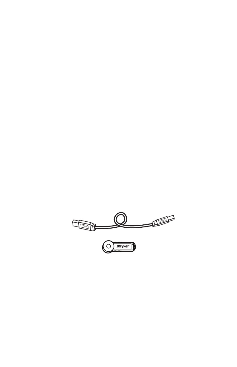
Package Contents
e Visum LED Light and Camera package includes the following components:
1. 50-foot USB Cable (SIDNE interface cable)
2. SIDNE Visum™ LED Surgical Light and Camera Driver 1.0 USB dongle
9
Page 10
Setup and Interconnection
Quick Startup Guide
is section outlines the startup instructions for experienced users. Refer to the
relevant section(s) of this manual for further details.
1. Power on the SIDNE® console.
2. Install the Visum™ LED Surgical Light and Camera Driver 1.0 upgrade.
SIDNE will power o.
3. Power on SIDNE. Wait for SIDNE to say, “SIDNE ready” before connecting
the Visum LED Light and Camera.
• ConnectthedeviceadaptercabletotheVisumLEDLightandCamera.
• ConnecttheSIDNEinterfacecabletoSIDNE.
4. Power on the Visum LED Light and Camera. SIDNE should say, “O.R.
Lights connected.”
Installing Driver Upgrade
e SIDNE Visum™ LED Surgical Light and Camera Driver Upgrade 1.0 allows
the SIDNE console to communicate with the Visum LED Light and Camera.
Caution Read the Operational Notes at the end of this procedure
before using the SIDNE console to control the Visum LED
Light and Camera.
Caution Do not attempt to install any other soware driver until the
installation of the Visum™ LED Surgical Light and Camera
Driver is complete and the SIDNE console has restarted.
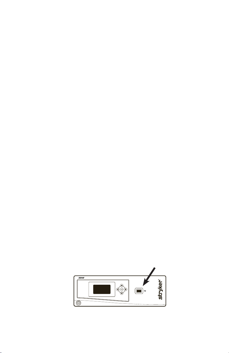
1. Power on the SIDNE console and wait until SIDNE says, “SIDNE ready.”
2. Insert the dongle into the device-driver dongle port on the front SIDNE
panel (see below).
10
Page 11

3. Follow the voice instructions given by SIDNE. To avoid equipment damage,
please do not remove the dongle card before SIDNE® says, “Please remove
card.” Aer installation is complete, SIDNE® will power o.
When SIDNE says this... Do this...
“Soware card detected. Please stand by.” Wait for the next instruction.
Do not remove the dongle until
SIDNE says, “Please remove card.”
“Soware installation started. Please wait.” Wait for the next instruction.
“Programming started.”
“10% complete, 20% complete...”
“Programming failed.” SIDNE will announce this message
“Programming complete. Please wait.” Wait for the next instruction.
“Soware installation complete.” Wait for the next instruction.
“Please remove card.” Remove the dongle.
Wait for the next instruction.
only if the programming failed. If
this occurs, follow the steps below:
1. Remove the dongle,
restart SIDNE, and
insert the dongle.
2. If the same problem
occurs again, contact
Stryker Technical
Support.
4. Power SIDNE on. When SIDNE says, “SIDNE ready,” the driver is installed
and ready for use.
11
Page 12
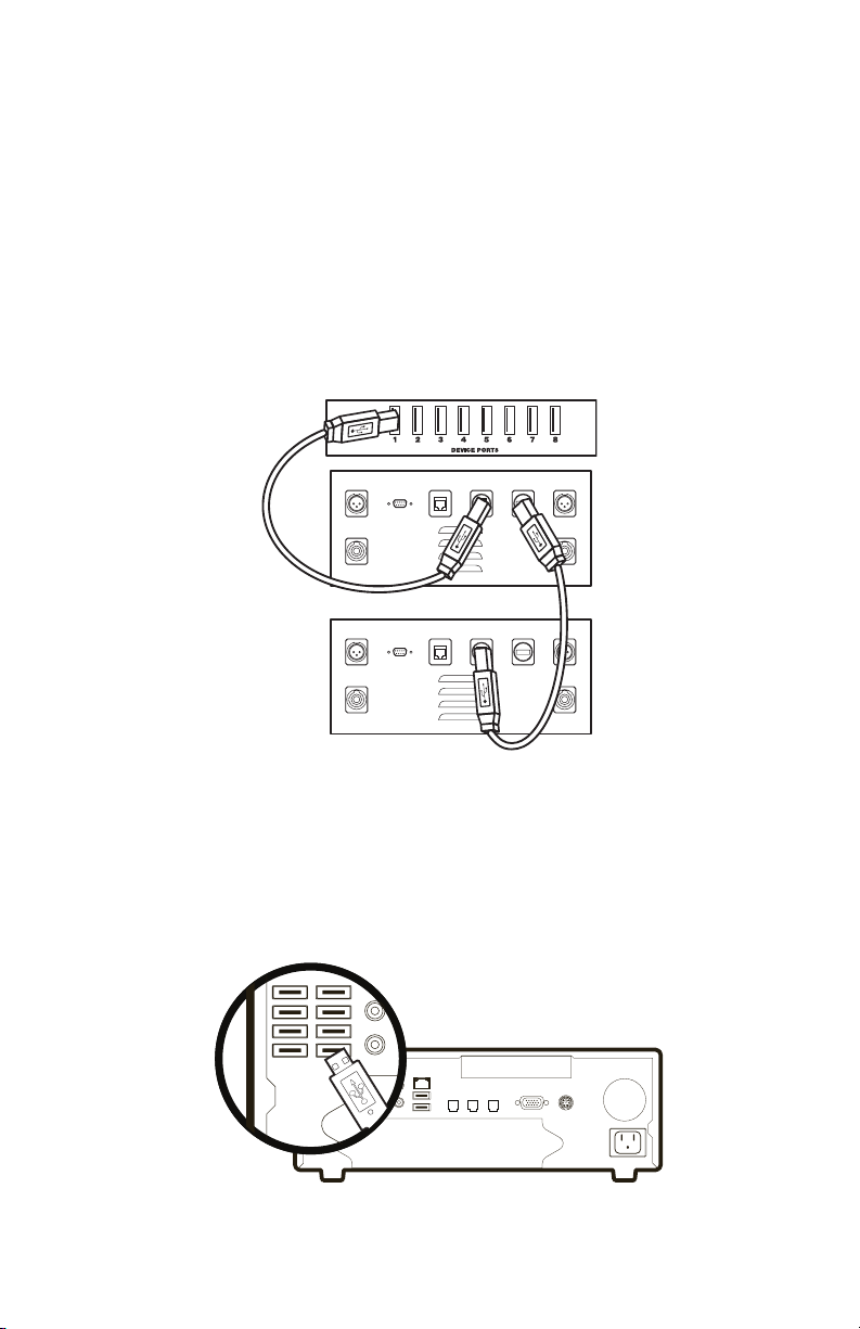
Connecting the Visum™ LED Light and Camera
to SIDNE
SIDNE can control up to four Visum LED Surgical Lights. To do this, a second
power control box is necessary. Use the Expansion port on the rst power supply
box to control the additional two lights.
To enable SIDNE to control four surgical lights, do the following:
1. Power on the lights and camera.
2. Power on SIDNE. Wait for SIDNE to say, “SIDNE ready.”
3. Connect the USB A – to – B (male) cable from an available SIDNE
®
device port to the SIDNE port on the rst power supply box.
4. Insert a second Stryker USB A – to – B cable into the expansion port.
5. Connect the 50-foot cable (leading from the expansion port) to the
SIDNE® port on the second power supply box (see diagram).
6. SIDNE should say, “O.R. Lights connected” within 20 seconds aer the
Visum LED Light and Camera and SIDNE have been connected. If this
does not occur, refer to the Troubleshooting section of this manual for
instructions.
12
Page 13

Operation
Status Bar
e status bar, shown below, appears at the bottom of the monitor screen.
1 2 3
1. Indicates the brightness level of the last light accessed.
2. Indicates the focus setting of the in-light camera.
3. Indicates the the shutter setting of the in-light camera.
13
Page 14
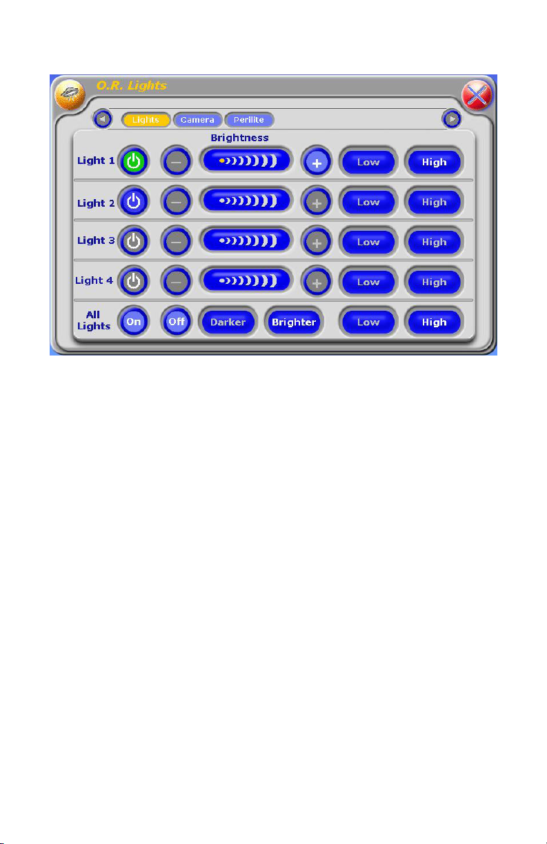
O.R. Lights Touchscreen
14
Page 15

Operating Room Lights
Touchscreen Commands
e following table describes the tablet buttons and level meters and their
function.
Button Group Buttons/Levels Description
Light–specic
controls
All light
controls
Power Powers on/o a particular light. Green
indicates the light is on. Blue indicates the
light is o.
Brightness level Increases or decreases the light intensity.
e range is from 1 through 8. If this
button has a gray background, the light
is at the maximum intensity.
High Sets a light to the maximum intensity.
If this button has a gray background,
the light is at the maximum intensity.
Low Sets a light to the minimum intensity.
If this button has a gray background,
the light is at the minimum intensity.
+ Increases the intensity of a light by one
unit. If this button has a gray background,
the light is at the maximum intensity.
- Decreases the intensity of a light by one
unit. If this button has a gray background,
the light is at the minimum intensity.
On Powers on all the lights. If this button has
a gray background, at least one light is on.
O Powers o all the lights. If this button has
a gray background, all lights are o.
High Sets all lights to the maximum intensity.
Low Sets all lights to the minimum intensity.
Brighter Increases the intensity of all lights by one
unit. If this button has a gray background,
the light is at the maximum intensity.
Darker Decreases the intensity of all lights by one
unit. If this button has a gray background,
the light is at the minimum intensity or
is o.
15
Page 16
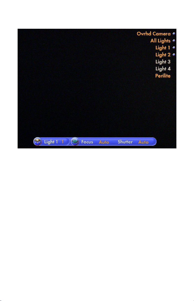
LED Lights Menu
16
Page 17

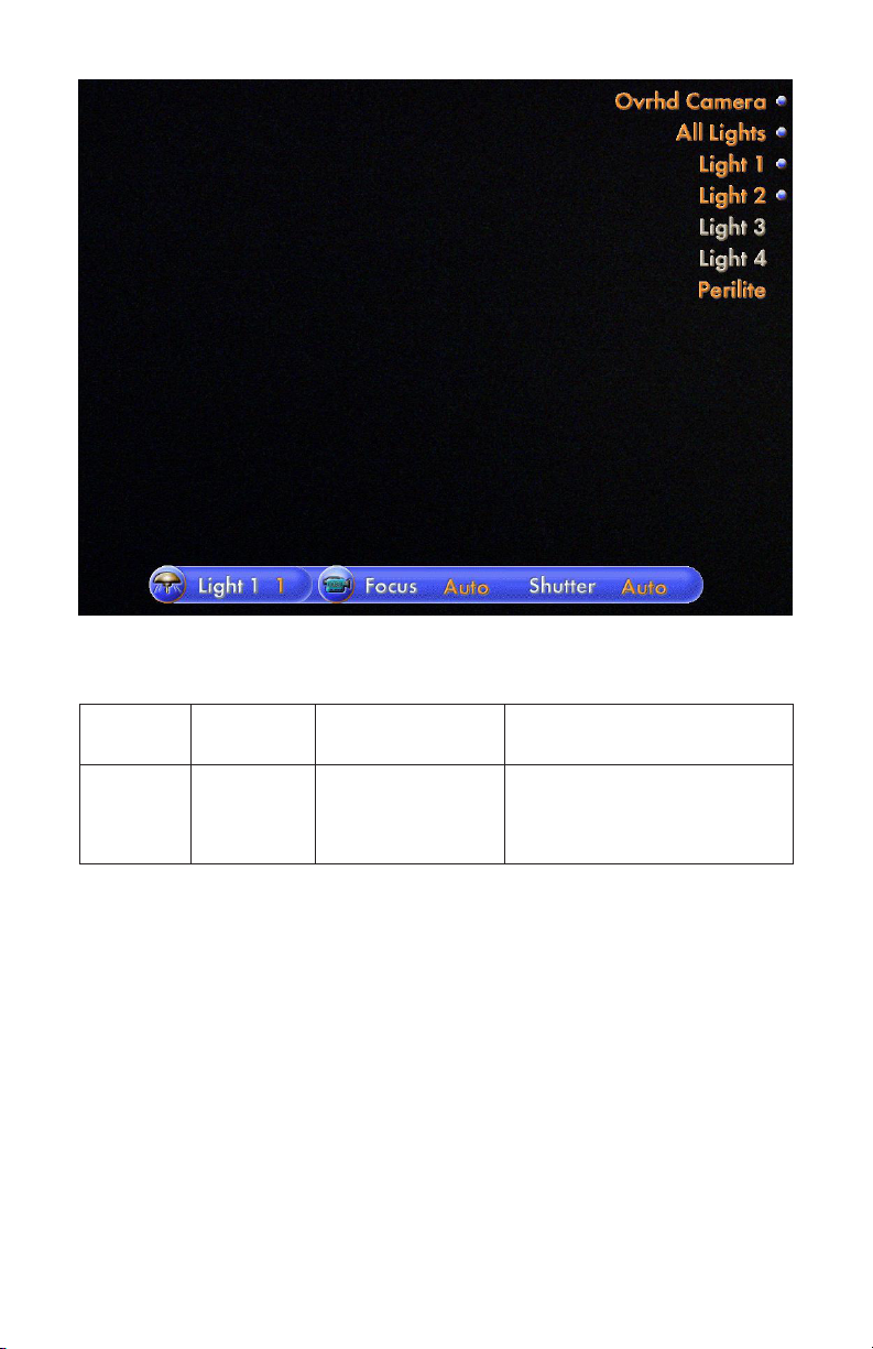
Voice Commands
e following table shows the SIDNE® voice commands for controlling the
Visum™ LED Surgical Lights.
Top Level Device
Selection
SIDNE O. R.
Lights
Function Selection Description
Light 1, Light 2,
Light 3, or Light 4
All lights Activate Powers on all the
Activate Powers on the light.
Brighter Increase the light
intensity by one unit.
Darker Decreases the light
intensity by one unit.
High Sets the light intensity
to maximum.
Low Sets the light intensity
to minimum.
O Powers o the light.
connected lights.
Brighter Increases the light
intensity of all
connected lights
by one unit.
Darker Decreases the light
intensity of all
connected lights
by one unit.
High Sets the light intensity
of all the connected
lights to maximum.
Low Sets the light intensity
of all the connected
lights to minimum.
O Powers o all the
connected lights.
17
Page 18

SIDNE® Announcements
Voice Message Playback Condition
Connected Visum™ LED Surgical Lights are powered on and
connected to SIDNE.
Disconnected Visum LED Surgical Lights are disconnected or
powered o.
Light error An error has been reported on one or more
of the connected Visum LED Surgical Lights.
Servicing may be necessary.
O. R. lights … Added as a prex added to a feedback message
when not in the O. R. Lights voice command
menu.
Operating Notes
1. Use the activate or the brightness commands to turn on any light when
the darker and o buttons are gray.
2. A status bar will be displayed on the monitor when using voice control.
e far le section shows the brightness level of the last individual light
accessed using the voice menu or, by default, the lowest numbered light
head connected. Say “Light” with the number of the desired light in the
“O.R. Lights” menu and the status bar will update to show the brightness
of that light. For example, say “Light 2” to see the brightness lights.
18
Page 19
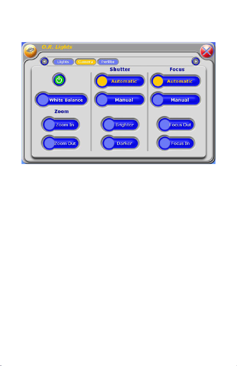
StrykeCam™ 2 In-Light Camera
Camera Touchscreen Menu
19
Page 20

Touchscreen Commands
e following table describes the tablet commands and their functions.
Button Group Buttons/Levels Description
Power Power Powers on/o a particular light. Green
indicates the light is on. Blue indicates
the light is o.
Shutter Automatic Sets the camera to automatic shutter
control. Orange indicates the camera
is set to automatic shutter control.
Manual Sets the camera to manual shutter
control. Orange indicates the camera
is set to manual shutter control.
Brighter Increases the shutter speed by one unit.
Gray indicates the camera is at maximum
shutter speed. Using this button will set
the camera to manual shutter mode.
Darker Decreases the shutter speed by one unit.
Gray indicates the camera is at minimum
iris. Using this button will set the camera
to manual iris mode.
Focus Automatic Sets the camera to automatic focus control.
Orange indicates the camera is set to
automatic focus control.
Manual Sets the camera to manual focus control.
Orange indicates the camera is set to
manual focus control.
Focus out Begins to focus out of the current view.
Releasing the button will stop the focus
out. A gray background indicates the
camera is at the maximum focus. Using
this button will set the camera to manual
focus mode.
Focus in Begins to focus into the current view.
Releasing the button will stop the focus in.
A gray background indicates the camera is
at the minimum focus. Using this button
will set the camera to manual focus mode.
20
Page 21
Zoom controls Zoom out Begins to zoom out to a wide-angle view.
Releasing the button will stop the zoom.
A gray background indicates the camera
is at the minimum zoom.
Zoom in Begins to zoom in to a telephoto view.
Releasing the button will stop the zoom.
A gray background indicates the camera
is at the maximum zoom.
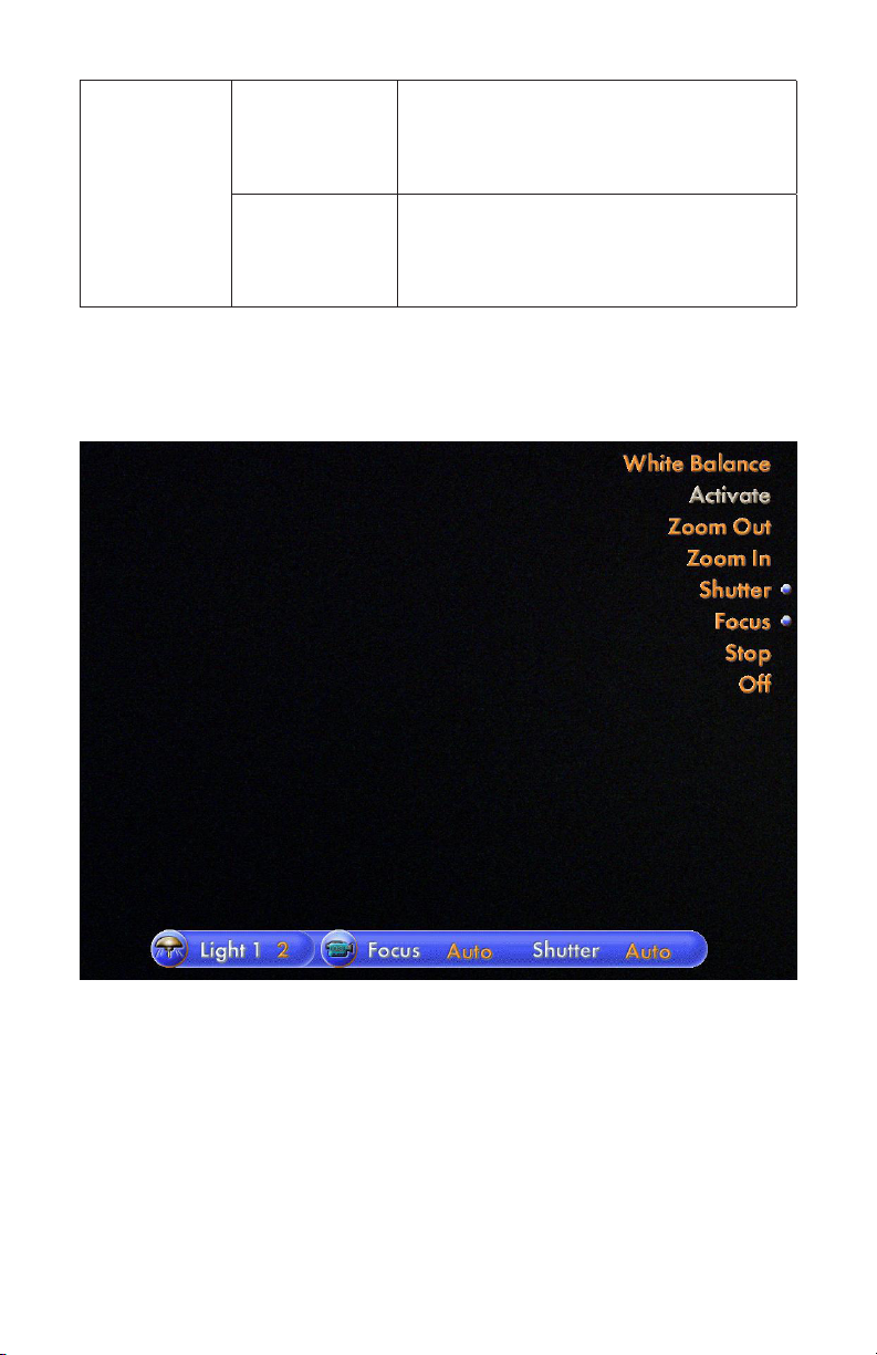
StrykeCam 2 In-Light Camera Voice Menu
21
Page 22

Voice Commands
e following table shows the SIDNE® voice commands for controlling the
StrykeCam 2 In-Light Camera.
Top
Level
SIDNE O.R.
Device Function Selection Description
lights
Overhead
camera
Activate Powers on the camera.
Zoom out Continuously zooms out
to a wide-angle view.
Zoom in Continuously zooms
in to a telephoto view.
Stop Stops the zoom command.
Shutter Automatic Sets Iris/shutter to
automatically control
brightness.
Manual Sets Iris/shutter to
manually control
brightness.
Brighter Continuously increases
the light level until the
stop command or other
camera command is given.
Darker Continuously decreases
the light level until the
stop command or other
camera command is given.
Stop Stops the shutter
adjustment.
22
Page 23

Focus Automatic Sets the camera to
automatic focus mode.
Manual Sets the camera to
manual focus mode.
Out Continuously focuses
the camera out until the
stop command or other
camera command is given.
In Continuously focuses
the camera in until the
stop command or other
command is given.
Stop Stops the camera from
focusing.
O Powers o the camera.
Note: Continuously means until “Stop” is said or pressed by the user,
or within 5 seconds, whichever occurs rst.
23
Page 24

Operating Notes
1. While the camera is executing any of the following voice commands
initiated by the SIDNE® interface—Zoom in, Zoom out, Focus in,
Focus out, Shutter brighter, Shutter darker—the command will continue
executing until
• thestopcommandoranothercameracommandhasbeenissued
• ithasreacheditsmaximumorminimumlimit
• thecommandtimesout.
2. Issuing a camera command other than stop will stop the current execution
and start the execution of the new command issued.
3. Please note that there is no indication on the SIDNE® Interface (Voice
and Tablet) regarding the maximum and minimum limits for the following
commands:
• Brightness/Darkness
• FocusIn/Out
• ZoomIn/Out
e only indication when these quantities have reached their limits will
be when the appropriate buttons/commands are grayed out.
4. A status bar will be displayed on the monitor when using voice control.
e center section shows the status of the camera focus and camera shutter
modes, either automatic, manual, or o.
24
Page 25
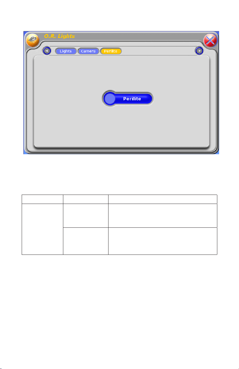
Perilite
Touchscreen Commands
e following table describes the tablet buttons and level meters and their
function.
Button Buttons/Levels Description
Ambient light
control
Power Powers on/o ambient light, if connected.
Green indicates the light is on. Blue indicates
the light is o.
Perilite one press = light one on
second press = light two on
third press = both lights o
25
Page 26
Voice Commands
Table X shows the SIDNE® voice commands for controlling the Visum Perilite.
Top Level Device
Selection
SIDNE O. R. lights Perilite say once = light one on
26
Function
Selection
Description
say again = light two on
say again = both lights o
Page 27

Troubleshooting
e table below shows the most common errors and possible solutions to each.
Problem Solution
No access to device through SIDNE® Attempt the following steps in order:
• EnsureSIDNE®ispoweredon.
• EnsuretheVisumLEDLight
and Camera is powered on
and connected to SIDNE.
If the problem persists, contact Stryker Technical Support: +1.800.624.4422.
27
Page 28

Page 29

Sommaire
Avertissements et précautions d’emploi ............. 31
Description du produit ................................................... 33
Utilisation prévue ..................................................................33
Contenu du module ..............................................................33
Installation et interconnexion .................................... 34
Guide de démarrage rapide ..................................................34
Installation de la mise à niveau du pilote ..............................34
Connexion de la lampe à DEL et de la caméra Visum™
au SIDNE® ............................................................................36
Utilisation ............................................................................... 37
Utilisation des éclairages de la salle .....................................39
Caméra à lampe intégrée StrykeCam™ 2 ............................43
Perilite ...................................................................................49
Dépannage ........................................................................... 51
Page 30

Page 31

Avertissements et précautions
d’emploi
Lire intégralement ce manuel et en suivre attentivement les instructions. Les
termes « avertissement », « précautions d’emploi » et « remarque » ont des
signications particulières et doivent être pris en considération avec toute
l’attention qui s’impose :
Avertissement Les avertissements signalent des risques pour la sécurité
du patient ou de l’utilisateur. Le non-respect de ces
avertissements peut entraîner des blessures pour le patient
ou l’utilisateur.
Précaution Les précautions d’emploi signalent des risques pour
d’emploi l’équipement. Le non-respect de ces précautions d’emploi
peut endommager l’appareil.
Remarque Les remarques fournissent des informations spéciales
permettant de clarier les instructions ou présentent d’autres
informations utiles.
Un point d’exclamation dans un triangle est destiné à attirer
l’attention de l’utilisateur sur la présence d’instructions
d’utilisation et d’entretien importantes dans le manuel.
Un éclair dans un triangle avertit l’utilisateur de la présence
d’une tension électrique dangereuse. Faire appel au personnel
agréé pour toute assistance technique.
Avertissement Pour éviter des blessures graves à l’utilisateur et au patient
et/ou des dommages à cet appareil, il convient de tenir
compte des avertissements suivants :
1. Lire entièrement ce manuel et vous familiariser avec son contenu avant
d’utiliser le matériel.
2. L’usage de la lampe chirurgicale à DEL et de la caméra Visum™ est réservé
aux médecins qualiés et aux techniciens familiarisés avec l’appareil
et les équipements auxquels ils se connectent. Une mauvaise utilisation
de la lampe chirurgicale à DEL et de la caméra Visum™ peut entraîner
des blessures chez le patient et/ou endommager les composants du système.
3. Déballer soigneusement l’appareil et vérier qu’il n’a pas été endommagé
au cours de l’expédition. Si des dommages sont constatés, NE PAS
utiliser le matériel.
4. Il convient de toujours être conscient de la position de la table par
rapport au patient et à son environnement.
31
Page 32

Avertissement An d’éviter des risques de lésions graves pour l’utilisateur
et le patient et/ou d’endommagement de l’appareil, il
convient de tenir compte des avertissements électriques
suivants :
1. Toujours mettre hors tension la lampe chirurgicale à DEL et la caméra
Visum™ lors de la connexion ou de la déconnexion des accessoires.
2. Avant et après chaque utilisation, inspecter l’isolation du cordon an
de repérer d’éventuels ssures, entailles, coupures, coups ou dépressions.
Toute irrégularité diminuerait l’ecacité de l’isolation et pourrait
provoquer l’électrocution du patient et/ou du personnel de la salle
d’opération.
32
Page 33

Description du produit
Le module SIDNE® Stryker de lampe chirurgicale à DEL Visum™ et de caméra
à lampe intégrée StrykeCam™ 2 (module de lampe chirurgicale à DEL et de
caméra Visum) est une interface logicielle entre le système de commande
d’appareil SIDNE et la lampe chirurgicale à DEL et la caméra Visum™ permettant
l’exécution des commandes vocales et par écran tactile de la lampe à DEL et de la
caméra Visum.
Remarque : Pour acheter la version du module de lampe chirurgicale à DEL et de
caméra Visum compatible avec SIDNE, contacter le représentant local de Stryker.
Utilisation prévue
Le module de lampe chirurgicale à DEL et de caméra Visum vise à permettre
aux utilisateurs du SIDNE de contrôler ce module par commandes vocales
ou tactiles. Il est conçu pour être utilisé lors des interventions chirurgicales
exigeant une caméra et un éclairage plafonnier. Il peut être utilisé dans toute
salle d’opération où la lampe à DEL et la caméra Stryker Visum et le système
de commande d’appareil SIDNE sont installés.
Contenu du module
Le module de lampe chirurgicale à DEL et de caméra Visum comprend les
éléments suivants :
1. Câble USB de 15,24 m (câble d’interface SIDNE)
2. Dongle USB du pilote de la lampe chirurgicale à DEL et de la caméra
SIDNE Visum™ 1.0
33
Page 34

Installation et interconnexion
Guide de démarrage rapide
Cette section décrit les instructions de démarrage destinées aux utilisateurs
expérimentés. Pour plus de détails, se reporter aux sections concernées dans
ce manuel.
1. Mettre la console SIDNE® sous tension.
2. Installer la mise à niveau du pilote de la lampe chirurgicale à DEL et de
la caméra Visum™ 1.0. SIDNE se met hors tension.
3. Mettre le SIDNE sous tension. Attendre que le SIDNE dise « SIDNE
ready » (SIDNE prêt) avant de connecter la lampe à DEL et la caméra
Visum.
• ConnecterlecâbleadaptateurdudispositifàlalampeàDELetàla
caméra Visum.
• Connecterlecâbled’interfaceSIDNEauSIDNE.
4. Mettre la lampe à DEL et la caméra Visum sous tension. SIDNE doit
dire « O.R. Lights connected » (Lampes SO connectées).
Installation de la mise à niveau du pilote
La mise à niveau du pilote de la lampe chirurgicale à DEL et de la caméra SIDNE
Visum™ 1.0 permet à la console SIDNE de communiquer avec la lampe à DEL
et la caméra Visum.
Précaution d’emploi Lire la section Remarques concernant l’utilisation
située à la n de cette procédure avant d’utiliser la
console Sidne pour commander la lampe à DEL et la
caméra Visum.
Précaution d’emploi Ne pas essayer d’installer un autre pilote logiciel tant
que l’installation du pilote de la lampe chirurgicale à
DEL et de la caméra Visum™ n’est pas terminée et que
la console SIDNE n’a pas redémarré.
1. Mettre la console SIDNE sous tension et attendre que le SIDNE dise
« SIDNE ready » (SIDNE prêt).
2. Insérer le dongle dans le port dongle du pilote du dispositif situé sur le
panneau avant du SIDNE (voir ci-dessous).
34
Page 35

3. Suivre les instructions vocales du SIDNE. Pour éviter d’endommager
le matériel, ne pas enlever la carte du dongle avant que le SIDNE® dise
« Please remove card » (Retirer la carte). Une fois l’installation terminée,
le SIDNE® s’éteint.
Lorsque le SIDNE dit... Procéder comme suit...
« Soware card detected. Please stand by. »
(Carte logicielle détectée. Merci de patienter.)
« Soware installation started. Please wait. »
(L’installation du logiciel a commencé.
Merci de patienter.)
« Programming started. »
(Programmation démarrée.)
« 10 % complete, 20 % complete... »
(10 % terminés, 20 % terminés...)
« Programming failed. » (Échec de la
programmation.)
« Programming complete. Please wait. »
(Programmation terminée. Merci de
patienter.)
« Soware installation complete. »
(Installation du logiciel terminée.)
« Please remove card. » (Retirer la carte.) Retirer le dongle.
Attendre l’instruction suivante.
Ne pas retirer le dongle tant que le
SIDNE n’a pas dit : « Please remove
card. » (Retirer la carte.)
Attendre l’instruction suivante.
Attendre l’instruction suivante.
Le SIDNE annonce ce message
uniquement si la programmation
a échoué. Dans ce cas, eectuer les
étapes suivantes :
1. Retirer le dongle,
redémarrer le SIDNE
et insérer le dongle.
2. Si le même problème
se reproduit, contacter
l’assistance technique
Stryker.
Attendre l’instruction suivante.
Attendre l’instruction suivante.
4. Mettre le SIDNE sous tension. Lorsque le SIDNE dit « SIDNE ready »
(SIDNE prêt), le pilote est installé et prêt à l’emploi.
35
Page 36

Connexion de la lampe à DEL et de la caméra
Visum™ au SIDNE®
Le SIDNE peut commander jusqu’à quatre lampes chirurgicales à DEL Visum.
Pour cela, un deuxième bloc de commande d’alimentation est nécessaire. Utiliser
le port d’extension sur le premier bloc d’alimentation pour commander les deux
lampes additionnelles.
Pour permettre à SIDNE de commander quatre lampes chirurgicales, procéder
comme suit :
1. Mettre les lampes et la caméra sous tension.
2. Mettre le SIDNE sous tension. Attendre que le SIDNE dise
« SIDNE ready » (SIDNE prêt).
3. Raccorder le câble USB A/B (mâle) de tout port du dispositif SIDNE
disponible au port SIDNE sur le premier bloc d’alimentation.
4. Introduire un deuxième câble USB A/B Stryker dans le port d’extension.
5. Connecter le câble de 15,24 m (allant du port d’extension) au port
SIDNE® sur le deuxième bloc d’alimentation (voir le diagramme)
6. Le SIDNE devrait dire « O.R. Lights connected » (Lampes SO connectées)
une vingtaine de secondes après la connexion de la lampe à DEL et de la
caméra Visum, et du SIDNE. Dans le cas contraire, se reporter au Guide
de dépannage de ce manuel pour d’autres instructions.
36
Page 37

Utilisation
Barre d’état
La barre d’état illustrée ci-dessous apparaît au bas de l’écran du moniteur.
1 2 3
1. Indique la luminosité de la dernière lampe activée.
2. Indique le réglage de la mise au point de la caméra à lampe intégrée.
3. Indique le réglage de l’obturateur de la caméra à lampe intégrée.
37
Page 38

Écran tactile O.R. Lights (Lampes SO)
38
Page 39

Utilisation des éclairages de la salle
Commandes par écran tactile
Le tableau suivant décrit les boutons de la tablette, les compteurs de niveau
et leurs fonctions.
Groupe de
boutons
Commandes
spéciques
aux lampes
Commandes
de toutes les
lampes
Boutons/
Niveaux
Mise sous/
hors tension
Brightness
level (Niveau
de luminosité)
High (Élevé) Règle une lampe sur l’intensité maximale. Si ce
Low (Faible) Règle une lampe sur l’intensité minimale. Si ce
+ Augmente d’une unité l’intensité d’une lampe.
- Réduit d’une unité l’intensité d’une lampe.
On (Actif) Allume toutes les lampes. Si ce bouton est grisé,
O (Inactif) Éteint toutes les lampes. Si ce bouton est grisé,
High (Élevé) Règle toutes les lampes sur l’intensité maximale.
Low (Faible) Règle toutes les lampes sur l’intensité minimale.
Brighter (Plus
lumineux)
Darker (Plus
sombre)
Description
Allume/éteint une lampe donnée. De couleur
verte, indique que la lampe est allumée.
De couleur bleue, indique que la lampe
est éteinte.
Augmente ou réduit l'intensité de la lampe.
Le niveau est compris entre 1 et 8. Si ce bouton
est grisé, cela signie que la lampe a atteint
l’intensité maximale.
bouton est grisé, cela signie que la lampe
a atteint l’intensité maximale.
bouton est grisé, cela signie que la lampe a
atteint l’intensité minimale.
Si ce bouton est grisé, cela signie que la lampe
a atteint l’intensité maximale.
Si ce bouton est grisé, cela signie que la lampe
a atteint l’intensité minimale.
cela signie qu’une lampe au moins est allumée.
cela signie que toutes les lampes sont éteintes.
Augmente d’une unité l’intensité de toutes les
lampes. Si ce bouton est grisé, cela signie que
la lampe a atteint l’intensité maximale.
Réduit d’une unité l’intensité de toutes les lampes.
Si ce bouton est grisé, cela signie que la lampe
a atteint l’intensité minimale ou est éteinte.
39
Page 40

Menu LED Lights (Lampes à DEL)
40
Page 41

Commandes vocales
Le tableau ci-dessous indique les commandes vocales du SIDNE® permettant
de contrôler les lampes chirurgicales à DEL Visum™.
Premier
niveau
SIDNE O. R.
Sélection
dispositif
Lights
(Lampes
SO)
du
Sélection de la fonction Description
Light 1, Light 2,
Light 3, or Light
4 (Lampe 1,
Lampe 2,
Lampe 3 ou
Lampe 4)
All lights
(Toutes les
lampes)
Activate
(Activer)
Brighter
(Plus
lumineux)
Darker
(Plus
sombre)
High
(Élevé)
Low
(Faible)
O
(Inactif)
Activate
(Activer)
Brighter
(Plus
lumineux)
Darker
(Plus
sombre)
High
(Élevé)
Low
(Faible)
O
(Inactif)
Allume la lampe.
Augmente d’une unité
l’intensité de la lampe.
Réduit d’une unité
l’intensité de la lampe.
Règle l’intensité de
la lampe au niveau
maximum.
Règle l’intensité de
la lampe au niveau
minimum.
Éteint la lampe.
Allume toutes les
lampes connectées.
Augmente d’une unité
l’intensité de toutes les
lampes connectées.
Réduit d’une unité
l’intensité de toutes les
lampes connectées.
Règle l’intensité
de toutes les lampes
connectées au
maximum.
Règle l’intensité
de toutes les lampes
connectées
au minimum.
Éteint toutes les
lampes connectées.
41
Page 42

Annonces concernant le SIDNE®
Message vocal Lecture
Connected (Connecté) Les lampes chirurgicales à DEL Visum™ sont
allumées et connectées au SIDNE.
Disconnected
(Déconnecté)
Light error
(Erreur de lampe)
O. R. lights… (Lampes
SO…)
Les lampes chirurgicales à DEL Visum sont
déconnectées ou éteintes.
Une erreur a été signalée sur une ou plusieurs
des lampes chirurgicales à DEL Visum
connectées. Une réparation peut être nécessaire.
Ajouté en préxe à un commentaire audio,
lorsque le menu par commande vocale O.R.
Lights (Lampes SO) n’est pas activé.
Remarques concernant l’utilisation
1. Utiliser les commandes activate (Activer) ou brightness (Luminosité)
pour allumer une lampe lorsque les boutons darker (Plus sombre) et o
(Éteint) sont grisés.
2. Une barre d’état apparaît sur le moniteur lorsque la commande vocale
est utilisée. L’extrémité gauche indique le niveau de luminosité de
la dernière lampe activée à partir du menu vocal ou, par défaut, la
lampe connectée dont le numéro est le plus bas. Indiquer le mot
« Light » (Lampe) suivi du numéro de la lampe souhaitée dans le menu
« O.R. Lights » (Lampes SO) et la barre d’état entraîne le réglage de la
luminosité de la lampe en conséquence. Par exemple, dire « Light 2 »
(Lampe 2) pour acher les indicateurs de luminosité.
42
Page 43

Caméra à lampe intégrée StrykeCam™ 2
Menu de commandes par écran tactile de la caméra
43
Page 44

Commandes par écran tactile
Le tableau suivant décrit les commandes de la tablette et leurs fonctions.
Groupe de
boutons
Mise sous/
hors tension
Shutter
(Obturateur)
Focus (Mise
au point)
Boutons/
Niveaux
Mise sous/
hors tension
Automatic
(Automatique)
Manual
(Manuel)
Brighter
(Plus
lumineux)
Darker
(Plus sombre)
Automatic
(Automatique)
Manual
(Manuel)
Focus out
(Mise au point
arrière)
Focus In (Mise
au point avant)
Description
Allume/éteint une lampe donnée. De couleur
verte, indique que la lampe est allumée. De
couleur bleue, indique que la lampe est éteinte.
Règle l’obturateur de la caméra en mode
automatique. De couleur orange, indique
que l’obturateur de la caméra est en mode
automatique.
Règle l’obturateur de la caméra en mode
manuel. De couleur orange, indique que
l’obturateur de la caméra est en mode manuel.
Augmente d’une unité la vitesse de l’obturateur.
Grisé, indique que l’obturateur de la caméra
est réglé sur la vitesse maximale. Ce bouton
permet de régler l’obturateur de la caméra
en mode manuel.
Réduit d’une unité la vitesse de l’obturateur. Grisé,
indique que la caméra a atteint le réglage
minimum de l’iris. Ce bouton permet de régler
l’iris de la caméra en mode manuel.
Règle la mise au point de la caméra en mode
automatique. De couleur orange, indique que
la mise au point de la caméra est en mode
automatique.
Règle la mise au point de la caméra en mode
manuel. De couleur orange, indique que la
mise au point de la caméra est en mode manuel.
Commence la mise au point arrière hors de la
vue actuelle. Relâcher le bouton pour arrêter
la mise au point arrière. Grisé, indique que
la caméra a atteint la mise au point maximale.
Ce bouton permet de régler la mise au point
de la caméra en mode manuel.
Commence la mise au point dans la vue actuelle.
Relâcher le bouton pour arrêter la mise au point
avant. Grisé, indique que la caméra a atteint
la mise au point minimale. Ce bouton
permet de régler la mise au point de la caméra
en mode manuel.
44
Page 45

Commandes
de zoom
Zoom out
(Zoom arrière)
Zoom in
(Zoom avant)
Applique un zoom arrière pour avoir une vue
grand angle. Relâcher le bouton pour arrêter
le zoom. Grisé, indique que la caméra a atteint
le zoom minimal.
Applique un zoom avant pour avoir une vue
au téléobjectif. Relâcher le bouton pour arrêter
le zoom. Grisé, indique que la caméra a atteint
le zoom maximal.
Menu vocal de la caméra à lampe intégrée StrykeCam 2
45
Page 46

Commandes vocales
Le tableau suivant indique les commandes vocales du SIDNE® permettant
de contrôler la caméra à lampe intégrée StrykeCam 2.
Premier
niveau
SIDNE O.R. lights
Dispositif Sélection de la fonction Description
(Lampes
SO)
Overhead
camera
(Caméra
suspendue)
Activate (Activer) Met la caméra sous
tension.
Zoom out (Zoom arrière) Eectue un zoom
arrière en continu
pour avoir une vue
grand angle.
Zoom in (Zoom avant) Eectue un zoom
avant en continu
pour avoir une vue
au téléobjectif.
Stop (Arrêter) Arrête la commande
de zoom.
Shutter
(Obturateur)
Automatic
(Automatique)
Manual
(Manuel)
Brighter
(Plus
lumineux)
Darker
(Plus
sombre)
Stop
(Arrêter)
Règle l’iris/
l’obturateur pour
qu’il commande
automatiquement la
luminosité.
Règle l’iris/
l’obturateur pour
qu’il commande
manuellement
la luminosité.
Augmente
continuellement
la luminosité jusqu'à
l’émission de la
commande d’arrêt
ou d’une autre
commande de la
caméra.
Réduit
continuellement
la luminosité jusqu’à
l’émission de la
commande d’arrêt
ou d’une autre
commande de la
caméra.
Arrête l’ajustement
de l’obturateur.
46
Page 47

Focus (Mise
au point)
O (Inactif) Met la caméra hors
Remarque : Continuellement signie jusqu’à ce que l’utilisateur dise
« Stop » ou appuie sur le bouton correspondant, ou au bout de
5 secondes, selon l’événement qui se produit en premier.
Automatic
(Automatique)
Manual
(Manuel)
Out
(Arrière)
In (Avant) Eectue
Stop
(Arrêter)
Règle la mise
au point de la
caméra en mode
automatique.
Règle la mise au
point de la caméra
en mode manuel.
Eectue
continuellement
la mise au point
arrière jusqu’à
l’émission
de la commande
d’arrêt ou d’une
autre commande
de la caméra.
continuellement la
mise au point avant
jusqu’à l’émission
de la commande
d’arrêt ou d’une
autre commande de
la caméra.
Arrête la mise au
point de la caméra.
tension.
47
Page 48

Remarques concernant l’utilisation
1. Lorsque la caméra exécute l’une des commandes vocales initiées par
l’interface SIDNE® — Zoom in (Zoom avant), Zoom out (Zoom arrière),
Focus in (Mise au point avant), Focus out (Mise au point arrière),
Shutter brighter (Obturateur plus clair), Shutter darker (Obturateur plus
sombre) — cette commande continuera de s’exécuter jusqu’à ce que :
• lacommanded’arrêtouuneautrecommandedelacamérasoit
émise ;
• elleaitatteintsalimitemaximumouminimum;
• lacommandeexpire.
2. L’envoi d’une commande de caméra autre que Stop (Arrêter) interrompt
la commande en cours et lance l’exécution de la nouvelle commande.
3. Noter que l’interface SIDNE® (interface vocale et interface de la tablette)
n’ache aucune indication quant aux limites maximale et minimale des
commandes suivantes :
• Brightness/Darkness(Luminosité/Obscurité)
• FocusIn/Out(Miseaupointavant/arrière)
• ZoomIn/Out(Zoomavant/arrière)
La seule indication donnée est que lorsque ces valeurs ont atteint leurs
limites, les boutons/commandes correspondants sont grisés.
4. Une barre d’état apparaît sur le moniteur lorsque la commande vocale
est utilisée. La section centrale indique l’état des modes de mise au point
et de l’obturateur de la caméra : Automatic (Automatique), Manual
(Manuel) ou O (Arrêt).
48
Page 49

Perilite
Commandes par écran tactile
Le tableau suivant décrit les boutons de la tablette, les compteurs de niveau
et leurs fonctions.
Bouton Boutons/
Niveaux
Ambient
light control
(Commande
de l’éclairage
ambiant)
Mise sous/
hors tension
Perilite première pression = lampe 1 allumée
Description
Active/désactive l’éclairage ambiant, s’il est
connecté. De couleur verte, indique que
la lampe est allumée. De couleur bleue,
indique que la lampe est éteinte.
deuxième pression = lampe 2 allumée
troisième pression = les deux lampes
sont éteintes
49
Page 50

Commandes vocales
Le tableau X indique les commandes vocales de SIDNE® permettant de contrôler
Visum Perilite.
Premier
niveau
SIDNE O. R. lights
50
Sélection
du dispositif
(Lampes
SO)
Sélection de la
fonction
Perilite première prononciation =
lampe 1 allumée
deuxième prononciation =
lampe 2 allumée
troisième prononciation =
les deux lampes sont éteintes
Description
Page 51

Dépannage
Le tableau ci-dessous présente les erreurs les plus courantes et les solutions
possibles pour chacune d’entre elles.
Problème Solution
Aucun accès à l’appareil via le SIDNE® Tenter les étapes suivantes, dans
l’ordre :
• S’assurerqueleSIDNE®
est sous tension.
• VérierquelalampeàDEL
Visum et la caméra sont
sous tension et connectées
au SIDNE.
Si le problème persiste, contacter le service d’assistance technique de Stryker
au +1.800.624.4422.
51
Page 52

Page 53

Inhalt
Warnhinweise und Vorsichtsmaßnahmen ........... 55
Produktbeschreibung ...................................................... 57
Einsatzbereich .......................................................................57
Verpackungsinhalt .................................................................57
Einrichtung und Anschlüsse ....................................... 58
Kurzanleitung zur Einrichtung ...............................................58
Installieren der Treiberaktualisierung .....................................58
Anschluss der Visum™ LED-Beleuchtungseinheit
und Kamera an SIDNE® .......................................................60
Bedienung .............................................................................. 62
OP-Beleuchtung ....................................................................64
Integrierbares Kamerasystem StrykeCam™ 2 ......................68
Perilite ...................................................................................75
Fehlerbehebung.................................................................. 77
Page 54

Page 55

Warnhinweise und Vorsichtsmaßnahmen
Lesen Sie dieses Handbuch bitte sorgfältig durch, und halten Sie sich genau an die
darin enthaltenen Anweisungen. Die Begrie „Warnung“, „Vorsicht“ und „Hinweis“
kennzeichnen wichtige Stellen dieses Handbuchs, die besonders zu beachten sind.
Warnung Macht auf Gefährdungen der Patienten- oder
Benutzersicherheit aufmerksam. Eine Nichtbeachtung der
Warnhinweise kann zur Verletzung des Patienten oder
Benutzers führen.
Vorsicht Macht auf Gefahren für die Geräte aufmerksam.
Eine Nichtbeachtung der Vorsichtshinweise kann eine
Beschädigung des Produkts verursachen.
Hinweis Enthält besondere Informationen zur Erläuterung von
Anweisungen oder weitere hilfreiche Informationen.
Das Ausrufungszeichen in einem Dreieck weist
den Anwender auf wichtige Bedienungs- und
Wartungsanweisungen im Handbuch hin.
Der Blitz in einem Dreieck kennzeichnet eine Warnung vor
gefährlicher Spannung. Alle Wartungsarbeiten dürfen nur
von autorisiertem Personal durchgeführt werden.
Warnung Um ernsthae Verletzungen des Benutzers und des
Patienten und/oder Beschädigungen am Gerät zu
vermeiden, sind folgende Warnhinweise zu beachten:
1. Lesen Sie vor dem Einsatz dieses Geräts das Handbuch gründlich durch,
und machen Sie sich mit dem Inhalt vertraut.
2. Die Visum™ chirurgische LED-Beleuchtung und Kamera sowie die
angeschlossene Ausrüstung dürfen nur von qualizierten und mit
dem Gebrauch vertrauten Ärzten oder Technikern verwendet werden.
Unsachgemäßer Gebrauch der Visum™ chirurgischen LED-Beleuchtung
und Kamera kann zu Verletzungen des Patienten und/oder Schäden an
den Systemkomponenten führen.
3. Packen Sie die Einheit vorsichtig aus, und überprüfen Sie den Inhalt auf
Unversehrtheit. Bei festgestellten Beschädigungen darf das Gerät NICHT
verwendet werden.
4. Achten Sie stets auf die Position des Tisches, um den Patienten und
andere Objekte in der Umgebung nicht zu gefährden.
55
Page 56

Warnung Um das Risiko ernsthaer Verletzungen des Benutzers und
des Patienten und/oder Beschädigungen dieses Geräts zu
vermeiden, sind die folgenden elektrischen Warnhinweise
zu beachten:
1. Schalten Sie die Visum™ chirurgische LED-Beleuchtung und Kamera
stets aus, wenn Sie Zubehör anschließen bzw. vom Gerät trennen.
2. Vor und nach jedem Einsatz müssen Sie die Kabelisolierung auf
Risse, Kerben, Einschnitte, Beulen und Druckstellen überprüfen.
Unregelmäßigkeiten jeglicher Art mindern die Isolierwirkung und
können zu Stromschlägen an Patient oder OP-Personal führen.
56
Page 57

Produktbeschreibung
Das Paket bestehend aus der SIDNE® Stryker Visum™ chirurgischen LEDBeleuchtung und dem integrierbaren Kamerasystem StrykeCam™ 2 (Visum
chirurgische LED-Beleuchtung und Kamera - Paket) ist eine Sowareschnittstelle
zwischen dem SIDNE-Gerätesteuerungssystem und der Visum™ chirurgischen
LED-Beleuchtung und Kamera, die die Sprachsteuerung oder TouchscreenSteuerung der Visum LED-Beleuchtung und Kamera ermöglicht.
Hinweis: Eine SIDNE-kompatible Version des Pakets bestehend aus der Visum
chirurgischen LED-Beleuchtung und Kamera ist über die für Sie zuständige
Stryker-Vertretung erhältlich.
Einsatzbereich
Das Paket bestehend aus der Visum chirurgischen LED-Beleuchtung und Kamera
ermöglicht den SIDNE-Benutzern, die Visum chirurgische LED-Beleuchtung
und Kamera durch Sprach- und Touchscreen-Befehle zu steuern. Es ist zur
Verwendung bei allen Operationen vorgesehen, bei denen Overhead-Beleuchtung
und eine Kamera benötigt werden. Es kann in allen OP-Umgebungen verwendet
werden, in denen die Stryker Visum LED-Beleuchtung und Kamera und das
SIDNE-Gerätesteuerungssystem installiert sind.
Verpackungsinhalt
Das Paket bestehend aus der Visum LED-Beleuchtung und Kamera umfasst die
folgenden Komponenten:
1. 15-m-USB-Kabel (SIDNE-Schnittstellenkabel)
2. Treiber 1.0 für SIDNE Visum™ chirurgische LED-Beleuchtung und
Kamera – USB-Dongle
57
Page 58

Einrichtung und Anschlüsse
Kurzanleitung zur Einrichtung
In diesem Abschnitt wird kurz die Einrichtung des Gerätes für erfahrene
Benutzer beschrieben. Weitere Informationen nden Sie in den entsprechenden
Abschnitten dieses Handbuchs.
1. Schalten Sie die SIDNE®-Konsole ein.
2. Installieren Sie das Upgrade für den Treiber 1.0 für Visum™ chirurgische
LED-Beleuchtung und Kamera. SIDNE schaltet sich darauin aus.
3. Schalten Sie SIDNE ein. Bevor Sie die Visum LED-Beleuchtung und
Kamera anschließen, warten Sie auf die Sprachausgabe „SIDNE ready“
(SIDNE bereit).
• SchließenSiedasGeräteadapterkabelandieVisumLED-Beleuchtung
und Kamera an.
• SchließenSiedasSIDNE-SchnittstellenkabelanSIDNEan.
4. Schalten Sie die Visum LED-Beleuchtung und Kamera ein. Die SIDNESprachausgabe lautet „O.R. Lights connected“ (OP-Beleuchtung
angeschlossen).
Installieren der Treiberaktualisierung
Das Upgrade des Treibers 1.0 für die SIDNE Visum™ chirurgische LEDBeleuchtung und Kamera ermöglicht die Kommunikation zwischen der SIDNEKonsole und der Visum LED-Beleuchtung und Kamera.
Vorsicht Vor dem Einsatz der SIDNE-Konsole für die Steuerung
der Visum LED-Beleuchtung und Kamera sind die
Bedienungshinweise am Ende dieses Verfahrens durchzulesen.
Vorsicht Installieren Sie keine anderen Sowaretreiber, bevor die
Installation des Treibers für die Visum™ chirurgische LEDBeleuchtung und Kamera abgeschlossen und die SIDNEKonsole neu gestartet wurde.
58
Page 59

1. Schalten Sie die SIDNE-Konsole ein, und warten Sie auf die SIDNESprachausgabe „SIDNE ready“ (SIDNE bereit).
2. Stecken Sie den Dongle in den Gerätetreiber-Dongle-Anschluss an der
SIDNE-Vorderseite (siehe unten).
3. Befolgen Sie die Anweisungen der SIDNE-Sprachausgabe.
Um Geräteschäden zu vermeiden, die Dongle-Karte erst nach der
SIDNE®-Sprachausgabe „Please remove card“ (Karte entfernen)
abziehen. Nach Abschluss der Installation wird SIDNE® ausgeschaltet.
SIDNE-Sprachausgabe Aktion
„Soware card detected. Please stand by.“
(Soware-Karte erkannt. Bitte warten)
„Soware installation started. Please
wait.“ (Sowareinstallation gestartet.
Bitte warten)
„Programming started.“
„10 % complete, 20 % complete...“
(Programmierung gestartet. 10 %
abgeschlossen, 20 % abgeschlossen)
„Programming failed.“ (Programmierung
fehlgeschlagen)
Warten Sie auf die nächste
Anweisung.
Entfernen Sie den Dongle erst nach
der SIDNE-Sprachausgabe „Please
remove card“ (Karte entfernen).
Warten Sie auf die nächste
Anweisung.
Warten Sie auf die nächste
Anweisung.
Diese SIDNE-Sprachausgabe erfolgt
nur, wenn die Programmierung
fehlgeschlagen ist. Führen Sie in
diesem Fall folgende Schritte aus:
1. Entfernen Sie den Dongle,
starten Sie SIDNE neu,
und stecken Sie den
Dongle wieder ein.
2. Wenn das gleiche Problem
erneut auritt, wenden Sie
sich an den technischen
Kundendienst von Stryker.
59
Page 60

„Programming complete. Please wait.“
(Programmierung abgeschlossen.
Bitte warten)
„Soware installation complete.“
(Sowareinstallation abgeschlossen)
„Please remove card.“ (Karte entfernen) Entfernen Sie den Dongle.
4. Schalten Sie SIDNE ein. Nach der SIDNE-Sprachausgabe „SIDNE
ready“ (SIDNE bereit) ist der Treiber installiert und einsatzbereit.
Warten Sie auf die nächste
Anweisung.
Warten Sie auf die nächste
Anweisung.
Anschluss der Visum™ LED-Beleuchtungseinheit und Kamera an SIDNE®
SIDNE kann bis zu vier Visum chirurgische LED-Beleuchtungseinheiten
steuern. Dazu ist eine zweite Power Box-Steuerung erforderlich. Über
den Erweiterungsanschluss am Netzteil werden die beiden weiteren
Beleuchtungseinheiten gesteuert.
Gehen Sie folgendermaßen vor, damit die Steuerung von vier chirurgischen
Beleuchtungseinheiten über SIDNE möglich ist.
1. Schalten Sie Beleuchtungseinheiten und die Kamera ein.
2. Schalten Sie SIDNE ein. Warten Sie auf die SIDNE-Sprachausgabe
„SIDNE ready“ (SIDNE bereit).
3. Schließen Sie das Kabel von USB A auf B (Stecker) zwischen einem
verfügbaren SIDNE-Geräteanschluss und dem ersten Netzteil an.
60
Page 61

4. Schließen Sie ein zweites Stryker-Kabel von USB A auf B am
Erweiterungsanschluss an.
5. Schließen Sie das 15-m-Kabel (vom Erweiterungsanschluss) an den
SIDNE-Anschluss am zweiten Netzteil an (siehe Abbildung).
6. Innerhalb von 20 Sekunden nach Anschluss der Visum LEDBeleuchtung und Kamera an SIDNE erfolgt die SIDNE-Sprachausgabe
„O.R. Lights connected“ (OP-Beleuchtung angeschlossen). Wenn das
nicht geschieht, nden Sie entsprechende Anweisungen im Abschnitt
„Fehlersuche“ dieses Handbuchs.
61
Page 62

Bedienung
Statusleiste
Die unten dargestellte Statusleiste wird am unteren Rand des Monitorbildschirms
angezeigt.
1 2 3
1. Gibt die zuletzt aufgerufene Helligkeitsstufe an.
2. Gibt den für die integrierte Kamera eingestellten Fokus an.
3. Gibt die für die integrierte Kamera eingestellte Blende an.
62
Page 63

Touchscreen für „O.R. Lights“ (OP-Beleuchtung)
63
Page 64

OP-Beleuchtung
Touchscreen-Befehle
Die folgende Tabelle beschreibt die Tablett-Schaltächen sowie die
Stufenanzeigen und deren Funktionen.
Schaltächengruppe
Beleuchtungsspezische
Regler
Schaltächen/
Stufen
Energie Schaltet eine bestimmte Leuchte ein/
Brightness
level
(Helligkeits stufe)
High (Hoch) Stellt eine Leuchte auf maximale Intensität
Low (Niedrig) Stellt eine Leuchte auf minimale Intensität
+ Erhöht die Intensität einer Leuchte jeweils
- Verringert die Intensität einer Leuchte
Beschreibung
aus. Grün bedeutet, dass die Beleuchtung
eingeschaltet ist. Blau bedeutet, dass die
Beleuchtung ausgeschaltet ist.
Erhöht oder verringert die Lichtstärke.
Der Bereich geht von 1 bis 8. Hat diese
Schaltäche einen grauen Hintergrund,
ist die Leuchte auf maximale Intensität
eingestellt.
ein. Hat diese Schaltäche einen grauen
Hintergrund, ist die Leuchte auf maximale
Intensität eingestellt.
ein. Hat diese Schaltäche einen grauen
Hintergrund, ist die Leuchte auf minimale
Intensität eingestellt.
um eine Einheit. Hat diese Schaltäche
einen grauen Hintergrund, ist die Leuchte
auf maximale Intensität eingestellt.
jeweils um eine Einheit. Hat diese
Schaltäche einen grauen Hintergrund,
ist die Leuchte auf minimale Intensität
eingestellt.
64
Page 65

Regler für
„All Lights“
(Alle Leuchten)
On (Ein) Schaltet alle Leuchten ein. Hat diese
Schaltäche einen grauen Hintergrund,
ist mindestens eine Leuchte eingeschaltet.
O (Aus) Schaltet alle Leuchten aus. Hat diese
Schaltäche einen grauen Hintergrund,
sind alle Leuchten ausgeschaltet.
High (Hoch) Stellt alle Leuchten auf maximale Intensität ein.
Low (Niedrig) Stellt alle Leuchten auf minimale Intensität ein.
Brighter
(Heller)
Darker
(Dunkler)
Erhöht die Intensität aller Leuchten jeweils
um eine Einheit. Hat diese Schaltäche
einen grauen Hintergrund, ist die Leuchte
auf maximale Intensität eingestellt.
Verringert die Intensität aller Leuchten
jeweils um eine Einheit. Hat diese
Schaltäche einen grauen Hintergrund,
ist die Leuchte auf minimale Intensität
eingestellt bzw. ausgeschaltet.
Menü für LED-Beleuchtung
65
Page 66

Sprachbefehle
In der folgenden Tabelle werden die SIDNE®-Sprachbefehle zur Steuerung der
Visum™ chirurgischen LED-Beleuchtung aufgeführt.
Oberste
Ebene
SIDNE O.R. Lights
Gerätewahl Funktionswahl Beschreibung
(OPBeleuchtung)
Light 1
(Leuchte 1),
Light 2
(Leuchte 2),
Light 3
(Leuchte 3)
oder Light 4
(Leuchte 4)
All lights
(Alle
Leuchten)
Activate
(Aktivieren)
Brighter
(Heller)
Darker
(Dunkler)
High
(Hoch)
Low
(Niedrig)
O (Aus) Schaltet die
Activate
(Aktivieren)
Brighter
(Heller)
Darker
(Dunkler)
High
(Hoch)
Low
(Niedrig)
O (Aus)
Schaltet die
Beleuchtung ein.
Erhöht die Lichtintensität um eine Einheit.
Verringert die Lichtintensität um eine Einheit.
Stellt die Lichtintensität
auf die maximale
Stufe ein.
Stellt die Lichtintensität auf
die minimale Stufe ein.
Beleuchtung aus.
Schaltet alle angeschlos-
senen Leuchten ein.
Erhöht die Lichtintensität
aller angeschlossenen
Leuchten jeweils um eine
Einheit.
Verringert die
Lichtintensität aller
angeschlossenen Leuchten
jeweils um eine Einheit.
Stellt alle angeschlossenen
Leuchten auf maximale
Lichtintensität ein.
Stellt alle angeschlossenen
Leuchten auf minimale
Lichtintensität ein.
Schaltet alle angeschlossenen Leuchten aus.
66
Page 67

SIDNE®-Meldungen
Sprachmitteilung Wiedergabesituation
Connected
(Angeschlossen)
Disconnected
(Nicht angeschlossen)
Light error
(Leuchtenfehler)
O. R. lights
(OP-Beleuchtung)
Die Visum™ chirurgischen LED-Beleuchtungen
sind eingeschaltet und an SIDNE angeschlossen.
Die Visum chirurgischen LED-Beleuchtungen
sind nicht angeschlossen oder ausgeschaltet.
Ein Fehler wurde für eine oder mehrere der
angeschlossenen Visum chirurgischen LEDBeleuchtungen gemeldet. Möglicherweise sind
Wartungsarbeiten erforderlich.
Wird einer Rückmeldung vorangestellt, wenn sich
der Benutzer nicht im Sprachmenü „O. R. Lights“
(OP-Beleuchtung) bendet.
Bedienungshinweise
1. Über die Befehle Activate (Aktivieren) oder Brightness (Helligkeit)
können Sie das Licht einschalten, wenn die Tasten Darker (Dunkler)
und O (Aus) grau angezeigt werden.
2. Bei Verwendung der Sprachsteuerung erscheint eine Statusleiste auf dem
Monitor. Im linken Bereich wird die Helligkeitsstufe der betreenden
Leuchte angezeigt, auf die zuletzt über das Sprachmenü zugegrien
wurde, oder standardmäßig der angeschlossene Beleuchtungskörper
mit der niedrigsten Nummer. Geben Sie den Sprachbefehl „Light“
(Beleuchtung) mit der Nummer der gewünschten Stufe im Menü „O.R.
Lights“ (OP-Beleuchtung) ein. In der Statusleiste wird darauin die
Helligkeit dieser Beleuchtung angezeigt. Wenn Sie z. B. den Sprachbefehl
„Light 2“ (Leuchte 2) geben, wird die Helligkeit für Leuchte 2 angezeigt.
67
Page 68

Integrierbares Kamerasystem StrykeCam™ 2
Touchscreen-Menü für Kamera
68
Page 69

Touchscreen-Befehle
Die folgende Tabelle beschreibt die Tablett-Befehle und deren Funktionen.
Schaltächengruppe
Energie Energie Schaltet eine bestimmte Leuchte ein/aus.
Shutter
(Blende)
Schaltächen/
Stufen
Automatic
(Automatisch)
Manual
(Manuell)
Brighter
(Heller)
Darker
(Dunkler)
Beschreibung
Grün bedeutet, dass die Beleuchtung
eingeschaltet ist. Blau bedeutet, dass die
Beleuchtung ausgeschaltet ist.
Stellt die Kamera auf automatische Blendenregelung ein. Orange bedeutet, dass die
Kamera auf automatische Blendenregelung
eingestellt ist.
Stellt die Kamera auf manuelle Blendenregelung ein. Orange bedeutet, dass die
Kamera auf manuelle Blendenregelung
eingestellt ist.
Erhöht die Verschlusszeit um eine Einheit.
Grau gibt an, dass die Kamera bereits auf die
maximale Verschlusszeit eingestellt ist. Mit
dieser Schaltäche wird die Kamera in den
manuellen Blendenmodus geschaltet.
Verringert die Verschlusszeit um eine
Einheit. Grau gibt an, dass die Kamera
bereits auf die minimale Verschlusszeit
eingestellt ist. Mit dieser Schaltäche
wird die Kamera in den manuellen
Blendenmodus geschaltet.
69
Page 70

Focus (Fokus) Automatic
(Automatisch)
Manual
(Manuell)
Focus out
(Fokus fern)
Focus in
(Fokus nah)
Zoomregler Zoom out
(Bildausschnitt
verkleinern)
Zoom in
(Bildausschnitt
vergrößern)
Stellt die Kamera auf automatische
Fokussierung ein. Orange bedeutet, dass
die Kamera auf automatische Fokussierung
eingestellt ist.
Stellt die Kamera auf manuelle Fokussierung
ein. Orange bedeutet, dass die Kamera auf
manuelle Fokussierung eingestellt ist.
Verkleinert den Bildausschnitt der aktuellen
Ansicht. Durch Loslassen der Schaltäche
wird die Verkleinerung des Bildausschnitts
beendet. Hat diese Schaltäche einen
grauen Hintergrund, ist die Kamera bereits
auf maximalen Fokus eingestellt. Mit
dieser Schaltäche wird die Kamera in den
manuellen Fokussierungsmodus geschaltet.
Vergrößert den Bildausschnitt der aktuellen
Ansicht. Durch Loslassen der Schaltäche
wird die Vergrößerung des Bildausschnitts
beendet. Hat diese Schaltäche einen grauen
Hintergrund, ist die Kamera bereits auf
minimalen Fokus eingestellt. Mit dieser
Schaltäche wird die Kamera in den
manuellen Fokussierungsmodus geschaltet.
Beginnt mit der Verkleinerung auf eine
Weitwinkelansicht. Durch Loslassen
der Schaltäche wird die Verkleinerung
gestoppt. Hat diese Schaltäche einen
grauen Hintergrund, ist die Kamera bereits
auf minimale Verkleinerung eingestellt.
Beginnt mit der Vergrößerung auf einer
Telefoto-Ansicht. Durch Loslassen der
Schaltäche wird die Vergrößerung
gestoppt. Hat diese Schaltäche einen
grauen Hintergrund, ist die Kamera bereits
auf maximale Vergrößerung eingestellt.
70
Page 71

Sprachmenü für integrierbares Kamerasystem StrykeCam 2
71
Page 72

Sprachbefehle
In der folgenden Tabelle werden die SIDNE-Sprachbefehle zur Steuerung der
integrierten Kamera StrykeCam 2 aufgeführt.
Oberste
Ebene
SIDNE O.R. lights
Gerät Funktionswahl Beschreibung
(O PBeleuchtung)
Overhead
camera
(OverheadKamera)
Activate (Aktivieren) Schaltet die
Kamera ein.
Zoom out
(Bildausschnitt
verkleinern)
Zoom in
(Bildausschnitt
vergrößern)
Stop (Anhalten) Stoppt den
Shutter
(Blende)
Automatic
(Automatisch)
Manual
(Manuell)
Brighter
(Heller)
Darker
(Dunkler)
Stop
(Anhalten)
Beginnt mit der
kontinuierlichen
Vergrößerung
auf eine
Weitwinkelansicht.
Beginnt mit der
kontinuierlichen
Vergrößerung
auf eine TelefotoAnsicht.
Zoom-Befehl.
Veranlasst die
automatische
Helligkeitsregelung
durch die Blende/
den Verschluss.
Veranlasst
die manuelle
Helligkeitsregelung
durch die Blende/
den Verschluss.
Erhöht
kontinuierlich die
Helligkeitsstufe, bis
der Stopp-Befehl
oder ein anderer
Kamerabefehl
ausgegeben wird.
Verringert
kontinuierlich die
Helligkeitsstufe, bis
der Stopp-Befehl
oder ein anderer
Kamerabefehl
ausgegeben wird.
Stoppt die
Blendenregelung.
72
Page 73

Focus
(Fokus)
O (Aus) Schaltet die
Hinweis: Kontinuierlich heißt, bis der Benutzer „Stop“ (Anhalten) sagt bzw. drückt
oder dass die Bewegung 5 Sekunden lang ausgeführt wird, je nachdem,
was zuerst eintritt.
Automatic
(Automatisch)
Manuell
(Manuell)
Out (Fokus
fern)
In (Fokus nah) Vergrößert
Stop
(Anhalten)
Stellt die
Kamera auf den
automatischen
Fokussierungsmodus ein.
Stellt die Kamera
auf den manuellen
Fokussierungsmodus ein.
Verkleinert
kontinuierlich
den Fokus, bis
der Stopp-Befehl
oder ein anderer
Kamerabefehl
ausgegeben wird.
kontinuierlich
den Fokus, bis
der Stopp-Befehl
oder ein anderer
Kamerabefehl
ausgegeben wird.
Stoppt die
Fokussierung.
Kamera aus.
73
Page 74

Bedienungshinweise
1. Während die Kamera einen der folgenden Befehle ausführt, die von der
SIDNE® -Bedienoberäche aus aktiviert wurden – Zoom in (Bildausschnitt
vergrößern), Zoom out (Bildausschnitt verkleinern), Focus in (Fokus nah),
Focus out (Fokus fern), Shutter brighter (Blende heller), Shutter darker
(Blende dunkler) - wird der Befehl weiterhin ausgeführt, bis
• derStoppbefehlodereinandererKamerabefehlausgegebenwird
• dieKameraihrenmaximalenoderminimalenGrenzwerterreichthat
• dasZeitlimitdesBefehlserreichtist.
2. Bei Ausgabe eines anderen Kamerabefehls als „Stop“ (Anhalten) wird
die Ausführung des aktuellen Befehls gestoppt und mit der Ausführung
des neuen Befehls begonnen.
3. Beachten Sie, dass für folgende Befehle auf der SIDNE®Bedienoberäche (Sprachoberäche und Tablett-Bedienoberäche)
keine Anzeige bezüglich der maximalen und minimalen Grenzwerte
vorhanden ist:
• Brightness/Darkness(Helligkeit/Dunkelheit)
• FocusIn/Out(Fokusnah/fern)
• ZoomIn/Out(Bildausschnittvergrößern/verkleinern)
Die einzige Anzeige dafür, dass die entsprechenden Grenzwerte erreicht
sind, ist, wenn die entsprechenden Schaltächen/Befehle ausgegraut sind.
4. Bei Verwendung der Sprachsteuerung wird eine Statusleiste auf
dem Monitor angezeigt. Im mittleren Bereich werden der Status der
Kamerafokussierung und die Kamera-Blendeneinstellungen, entweder
„Automatic“ (Automatisch), „Manual“ (Manuell) oder „O“ (Aus),
angezeigt.
74
Page 75

Perilite
Touchscreen-Befehle
Die folgende Tabelle beschreibt die Tablett-Schaltächen sowie die Stufenanzeigen
und deren Funktionen.
Schaltäche Schaltächen/
Stufen
Ambient
light control
(Umgebungslichtregler)
Energie Schaltet das Umgebungslicht ein/aus, sofern
Perilite Einmal drücken = Leuchte eins eingeschaltet
Beschreibung
es angeschlossen ist. Grün bedeutet, dass die
Beleuchtung eingeschaltet ist. Blau bedeutet,
dass die Beleuchtung ausgeschaltet ist.
Zweimal drücken = Leuchte zwei eingeschaltet
Dreimal drücken = beide Leuchten sind aus
75
Page 76

Sprachbefehle
Tabelle X zeigt die SIDNE®-Sprachbefehle für die Steuerung von Visum Perilite.
Oberste
Ebene
SIDNE O. R. lights
76
Gerätewahl Funktionswahl Beschreibung
(OPBeleuchtung)
Perilite Einmal sagen = Leuchte eins
eingeschaltet
Sprachausgabe wiederholen =
Leuchte zwei eingeschaltet
Sprachausgabe noch mal
wiederholen = beide Leuchten
sind aus
Page 77

Fehlerbehebung
In der nachfolgenden Tabelle nden Sie die häugsten Fehler und entsprechende
Lösungsvorschläge.
Problem Lösung
Kein Zugri auf das Gerät über SIDNE® Probieren Sie der Reihe nach die
folgenden Abhilfemaßnahmen aus:
• StellenSiesicher,dass
SIDNE® eingeschaltet ist.
• StellenSiesicher,dassdie
Visum LED-Beleuchtung und
Kamera eingeschaltet und an
SIDNE angeschlossen sind.
Wenn dieses Problem weiterhin besteht, wenden Sie sich an den technischen
Kundendienst von Stryker: +1.800.624.4422.
77
Page 78

Page 79

Indice
Messaggi di avvertenza e di attenzione .............. 81
Descrizione del prodotto ............................................... 83
Uso previsto ..........................................................................83
Contenuto della confezione ..................................................83
Installazione e interconnessioni............................... 84
Guida rapida ..........................................................................84
Installazione dell'aggiornamento del driver...........................84
Collegamento della lampada LED Visum™ e della
videocamera al sistema SIDNE® ...........................................86
Funzionamento.................................................................... 87
Lampade della sala operatoria ..............................................89
Videocamera StrykeCam™ 2 In-Light ..................................93
Perilite ...................................................................................99
Risoluzione dei problemi ........................................... 101
Page 80

Page 81

Messaggi di avvertenza e di attenzione
Leggere il manuale e attenersi scrupolosamente alle istruzioni. Le indicazioni di
avvertenza, attenzione e nota hanno un signicato particolare e vanno rispettate.
Avvertenza Indica la presenza di rischi relativi alla sicurezza del
paziente o dell'utente. L'inosservanza delle avvertenze
potrebbe arrecare danni al paziente o all'utente.
Attenzione Indica la presenza di un rischio per l'apparecchiatura.
L'inosservanza dei messaggi di attenzione potrebbe arrecare
danni al prodotto.
Nota Fornisce informazioni speciche per chiarire determinate
istruzioni o aggiungere ulteriori dettagli.
Un punto esclamativo inserito in un triangolo segnala
all'utente la presenza di importanti istruzioni per il
funzionamento e la manutenzione nel manuale allegato
al prodotto.
Il simbolo del fulmine inserito in un triangolo ha lo
scopo di avvisare della presenza di tensione pericolosa.
Demandare tutte le procedure di servizio a personale
autorizzato.
Avvertenza Per evitare gravi lesioni all'utente e al paziente e/o danni
al dispositivo, attenersi alle seguenti avvertenze:
1. Prima di utilizzare il dispositivo, leggere attentamente il presente
manuale e conoscere bene il suo contenuto.
2. La lampada scialitica LED Visum™ e la videocamera può essere utilizzata
esclusivamente da parte di un medico qualicato o di un tecnico esperto.
Un utilizzo non corretto della lampada scialitica LED Visum™ e della
videocamera può causare lesioni al paziente e/o danni ai componenti
del sistema.
3. Disimballare con cautela la confezione e vericare che non si siano
vericati danni durante il trasporto. Se si riscontrano danni, NON
utilizzare l'apparecchiatura.
4. Essere sempre consapevoli della posizione del lettino rispetto al paziente
e all'ambiente.
81
Page 82

Avvertenza Per evitare possibili gravi lesioni all'utente e al paziente e/o
danni al dispositivo, è necessario tenere in considerazione
le seguenti avvertenze elettriche:
1. Spegnere sempre la lampada scialitica LED Visum™ e la videocamera
quando si collegano o si scollegano gli accessori.
2. Prima e dopo ogni utilizzo, controllare l'isolamento del cavo vericando
che non siano presenti rotture, intaccature, tagli, rientranze o depressioni.
Qualunque irregolarità diminuisce l'ecacia dell'isolamento e può avere
come eetto scosse al paziente o al personale della sala operatoria.
82
Page 83

Descrizione del prodotto
La lampada scialitica LED Visum™ SIDNE® Stryker e il pacchetto per videocamera
StrykeCam™ 2 In-Light (pacchetto lampada scialitica LED Visum e videocamera)
è un'interfaccia soware tra il sistema di controllo del dispositivo SIDNE e la
lampada scialitica LED Visum™ e videocamera che consente il comando vocale
o tramite schermo tattile della lampada LED Visum e della videocamera.
Nota: per acquistare la versione SIDNE compatibile del pacchetto lampada
scialitica LED Visum e videocamera, contattare il rappresentante locale Stryker.
Uso previsto
Il pacchetto lampada LED Visum e videocamera consente agli utenti SIDNE
di controllare la lampada LED Visum e la videocamera per mezzo di comandi
vocali e a schermo tattile. Si utilizza in interventi chirurgici ove sia richiesta
illuminazione e video sospesi. È possibile utilizzarlo in qualsiasi sala operatoria
ove siano installati sia la lampada LED Visum Stryker e la videocamera, sia il
sistema di comando del dispositivo SIDNE.
Contenuto della confezione
Il pacchetto lampada LED Visum e videocamera include i seguenti componenti:
1. Cavo USB della lunghezza di 15,24 m (cavo interfaccia SIDNE)
2. Dispositivo di protezione elettronica USB Driver 1.0 per lampada
scialitica LED SIDNE Visum™ e videocamera
83
Page 84

Installazione e interconnessioni
Guida rapida
Questa sezione descrive le istruzioni di avvio per utenti esperti. Per ulteriori
dettagli consultare le relative sezioni di questo manuale.
1. Accendere la consolle SIDNE®.
2. Installare l'aggiornamento del Driver 1.0 della lampada scialitica LED
Visum™ e della videocamera. SIDNE si spegne.
3. Accendere SIDNE. Attendere che SIDNE emetta il messaggio vocale
"SIDNE ready"(SIDNE pronto) prima di collegare la lampada LED
Visum e la videocamera.
• CollegareilcavoadattatoreallalampadaLEDVisumealla
videocamera.
• CollegareilcavodiinterfacciaSIDNEalsistemaSIDNE.
4. Accendere la lampada LED Visum e la videocamera. SIDNE emetterà
il seguente messaggio vocale: "O.R. Lights connected" (Lampade sala
operatoria collegate).
Installazione dell'aggiornamento del driver
L'aggiornamento del driver 1.0 per lampada scialitica LED Visum™ SIDNE
e videocamera consente alla consolle SIDNE di comunicare con la lampada
LED Visum e la videocamera.
Attenzione Leggere le note operative al termine di questa procedura prima
di utilizzare la consolle SIDNE per comandare la lampada LED
Visum e la videocamera.
Attenzione Non tentare di installare altri driver soware nché
l'installazione del driver della lampada scialitica LED Visum™
e della videocamera non è stata completata e la consolle SIDNE
non è stata riavviata.
1. Accendere la consolle SIDNE e attendere che l'unità emetta il messaggio
vocale "SIDNE ready" (SIDNE pronto).
2. Inserire il dispositivo di protezione elettronica contenente il driver da
installare nell'apposita porta sul pannello anteriore del sistema SIDNE
(vedere in basso).
84
Page 85

3. Seguire le istruzioni vocali emesse da SIDNE. Per evitare danni
all'apparecchiatura, non rimuovere il dispositivo di protezione
elettronica prima che il sistema SIDNE® abbia comunicato "Please
remove card" (Rimuovere la scheda). Al termine dell'installazione
SIDNE® si spegne.
Messaggio vocale del sistema SIDNE Azione da eseguire
"Soware card detected. Please
stand by" (Rilevata scheda soware.
Attendere)
"Soware installation started. Please
wait." (Installazione soware avviata.
Attendere.)
"Programming started."
"10 % complete, 20 % complete..."
(Programmazione avviata. 10 %
completo, 20 % completo…)
"Programming failed."
(Programmazione non riuscita.)
"Programming complete. Please
wait." (Programmazione completata
Attendere.)
"Soware installation complete."
(Installazione soware completata.)
"Please remove card" (Rimuovere la
scheda)
Attendere l'istruzione successiva.
Non rimuovere il dispositivo di protezione
elettronica nché il sistema SIDNE
non emette il messaggio vocale "Please
remove card" (Rimuovere la scheda).
Attendere l'istruzione successiva.
Attendere l'istruzione successiva.
Il sistema SIDNE emette questo
messaggio soltanto se la programmazione
non si è conclusa correttamente.
In questo caso, seguire quanto
riportato di seguito:
1. Estrarre il dispositivo
di protezione elettronica,
riavviare il sistema SIDNE,
quindi reinserirlo.
2. Se si verica nuovamente
lo stesso problema, rivolgersi
all'assistenza tecnica Stryker.
Attendere l'istruzione successiva.
Attendere l'istruzione successiva.
Rimuovere il dispositivo di protezione
elettronica.
4. Accendere SIDNE. Quando SIDNE comunica "SIDNE ready" (SIDNE
pronto) il driver sarà stato installato e il sistema è pronto all'uso.
85
Page 86

Collegamento della lampada LED Visum™ e della videocamera al sistema SIDNE®
SIDNE è in grado di controllare no a quattro lampade scialitiche LED Visum.
Per eettuare questa operazione, è necessario un secondo alimentatore. Utilizzare
la porta di espansione sul primo alimentatore di rete per controllare le due
lampade supplementari.
Per abilitare SIDNE a controllare le quattro lampade scialitiche, procedere
come segue:
1. Accendere le lampade e la videocamera.
2. Accendere SIDNE. Attendere che SIDNE dica "SIDNE ready" (SIDNE
pronto).
3. Collegare il cavo USB A a B (maschio) da una porta disponibile per
i dispositivi SIDNE alla porta SIDNE sul primo alimentatore di rete.
4. Inserire un secondo cavo USB A a B Stryker nella porta di espansione.
5. Collegare il cavo di 15,24 m (che parte dalla porta di espansione) alla
porta SIDNE® sul secondo alimentatore di rete (vedere lo schema).
6. SIDNE emetterà il seguente messaggio vocale: "O.R. Lights connected"
("Lampade sala operatoria collegate") entro 20 secondi dopo che sono
state collegate la lampada LED Visum e la videocamera. In caso contrario,
consultare la Guida alla risoluzione dei problemi del presente manuale.
86
Page 87

Funzionamento
Barra di stato
La barra di stato, illustrata in basso, compare nella parte inferiore della schermata
del monitor.
1 2 3
1. Indica il livello di luminosità dell'ultima lampada selezionata.
2. Indica l'impostazione di messa a fuoco della videocamera in-light.
3. Indica l'impostazione dell'otturatore della videocamera in-light.
87
Page 88

Schermo tattile lampade per sala operatoria
88
Page 89

Lampade della sala operatoria
Comandi schermo tattile
Nella tabella seguente sono descritti i pulsanti della tavoletta, gli indici dei livelli
e le relative funzioni.
Gruppo di
pulsanti
Comandi
specici
delle
lampade
Comandi
All Lights
(Tutte le
lampade)
Pulsanti/Livelli Descrizione
Alimentazione Consente di accendere o spegnere una determinata
lampada. Verde indica che la lampada è accesa.
Blu indica che la lampada è spenta.
Brightness level
(Livello di
luminosità)
High (Alta) Consente di regolare una lampada alla massima
Low (Bassa) Consente di regolare una lampada all'intensità
+ Aumenta di una unità l'intensità di una determinata
- Riduce di una unità l'intensità di una determinata
On (Attiva) Consente di accendere tutte le lampade. Se il pulsante
O (Disattiva) Consente di spegnere tutte le lampade. Se il
High (Alta) Regola tutte le lampade alla massima intensità.
Low (Bassa) Regola tutte le lampade all'intensità minima.
Brighter
(Più chiaro)
Darker
(Più scuro)
Aumenta o diminuisce l'intensità della lampada.
L'intervallo va da 1 a 8. Se il pulsante ha uno sfondo
grigio, la lampada sta funzionando all'intensità
massima.
intensità. Se il pulsante ha uno sfondo grigio,
la lampada sta funzionando all'intensità massima.
minima. Se il pulsante ha uno sfondo grigio,
la lampada sta funzionando all'intensità minima.
lampada. Se il pulsante ha uno sfondo grigio,
la lampada sta funzionando all'intensità massima.
lampada. Se il pulsante ha uno sfondo grigio,
la lampada sta funzionando all'intensità minima.
ha uno sfondo grigio, è accesa almeno una lampada.
pulsante ha uno sfondo grigio, tutte le lampade
sono spente.
Aumenta di una unità l'intensità di tutte le lampade.
Se il pulsante ha uno sfondo grigio, la lampada sta
funzionando all'intensità massima.
Riduce di una unità l'intensità di tutte le lampade.
Se il pulsante ha uno sfondo grigio, la lampada sta
funzionando all'intensità minima o è spenta.
89
Page 90

Menu lampade LED
90
Page 91

Comandi vocali
La tabella seguente illustra i comandi vocali SIDNE® per il controllo delle
lampade scialitiche LED Visum™.
Livello
superiore
SIDNE O. R. lights
Selezione
dispositivo
(Lampade
sala
operatoria)
Selezione funzione Descrizione
Light 1,
Light 2,
Light 3,
o Light 4
(Lampada 1,
Lampada 2,
Lampada 3,
Lampada 4)
All lights
(Tutte le
lampade)
Activate
(Attivazione)
Brighter
(Più chiaro)
Darker
(Più scuro)
High (Alta) Imposta l'intensità
Low (Bassa) Imposta l'intensità
O
(Disattiva)
Activate
(Attivazione)
Brighter
(Più chiaro)
Darker
(Più scuro)
High (Alta) Imposta al massimo
Low (Bassa) Imposta al minimo
O
(Disattiva)
Accende la lampada.
Aumenta di una
unità l'intensità della
lampada.
Diminuisce di una
unità l'intensità della
lampada.
della lampada
al massimo.
della lampada
al minimo.
Spegne la lampada.
Accende tutte le
lampade collegate.
Aumenta di una
unità l'intensità
di tutte le lampade
collegate.
Riduce di una unità
l'intensità di tutte le
lampade collegate.
l'intensità di tutte le
lampade collegate.
l'intensità di tutte le
lampade collegate.
Consente di
spegnere tutte le
lampade collegate.
91
Page 92

Messaggi SIDNE®
Messaggio vocale Condizione per cui viene emesso
Connected (Collegato) Le lampade scialitiche LED Visum™ sono accese
e collegate a SIDNE.
Disconnected (Scollegato) Le lampade scialitiche LED Visum sono
scollegate o spente.
Light error (Errore
lampada)
O. R. lights …(Lampade
sala operatoria …)
È stato generato un errore da una o più delle
lampade scialitiche LED Visum collegate.
Può essere necessaria assistenza.
Viene aggiunto come presso a un messaggio
di risposta se non si è nel menu Comandi vocali
lampade sala operatoria.
Note operative
1. Utilizzare i comandi activate (Attivazione) o brightness (Luminosità)
per accendere una lampada quando i pulsanti darker (Più scuro) e o
sono disattivi.
2. Durante l'utilizzo dei comandi vocali, sul monitor sarà visualizzata
una barra di stato. La sezione all'estrema sinistra mostra il livello di
luminosità dell'ultima singola lampada chiamata utilizzando il menu
vocale o, per impostazione predenita, la lampada con il numero
d'ordine più basso collegata. Pronunciare "Light" (Lampada) insieme
al numero della lampada desiderata nel menu "O.R. Lights" ("Lampade
sala operatoria") e la barra di stato si aggiornerà per mostrare la
luminosità di quella lampada. Ad esempio, pronunciare "Light 2"
("Lampada 2") per vederne la luminosità.
92
Page 93

Videocamera StrykeCam™ 2 In-Light
Menu schermo tattile della videocamera
93
Page 94

Comandi schermo tattile
Nella tabella seguente sono descritti i comandi della tavoletta e le relative
funzioni.
Gruppo di
pulsanti
Alimentazione Alimentazione Consente di accendere o spegnere una determinata
Shutter
(Otturatore)
Focus (Messa
a fuoco)
Pulsanti/Livelli Descrizione
lampada. Il verde indica che la lampada è accesa. Il blu
indica la lampada è spenta.
Automatic
(Automatico)
Manual
(Manuale)
Brighter
(Più chiaro)
Darker
(Più scuro)
Automatic
(Automatico)
Manual
(Manuale)
Focus out
(Riduzione della
messa a fuoco)
Focus in
(Aumento della
messa a fuoco)
Imposta il controllo dell’otturatore della videocamera
su automatico. L'arancione indica che il controllo
dell'otturatore della videocamera è impostato su
automatico.
Imposta il controllo dell'otturatore della videocamera
su manuale. L'arancione indica che il controllo
dell'otturatore della videocamera è impostato su
manuale.
Aumenta la velocità dell'otturatore di una unità.
Il grigio indica che la videocamera è alla velocità
massima dell'otturatore. Selezionando questo pulsante
l'otturatore verrà impostato in modalità manuale.
Riduce la velocità dell'otturatore di una unità. Il grigio
indica che la videocamera è impostata all'apertura
minima del diaframma. Selezionando questo pulsante
verrà impostata la modalità manuale per il diaframma
della videocamera.
Imposta la messa a fuoco automatica della
videocamera. L'arancione indica che la messa a fuoco
della videocamera è impostata su automatico.
Imposta la messa a fuoco manuale della videocamera.
L'arancione indica che la messa a fuoco della
videocamera è impostata su manuale.
Comincia a ridurre la messa a fuoco della vista attuale.
Rilasciando il pulsante verrà arrestato l'allontanamento
della messa a fuoco. Uno sfondo grigio indica che
sulla videocamera è impostata la distanza massima
di messa a fuoco. Selezionando questo pulsante verrà
impostata la modalità di messa a fuoco manuale della
videocamera.
Comincia ad aumentare la messa a fuoco della
vista attuale. Rilasciando il pulsante verrà arrestato
l'aumento della messa a fuoco. Uno sfondo grigio
indica che sulla videocamera è impostata la distanza
minima di messa a fuoco. Selezionando questo
pulsante verrà impostata la modalità di messa a fuoco
manuale della videocamera.
94
Page 95

Comandi Zoom Zoom out
(Riduci)
Zoom in
(Ingrandisci)
Avvia la riduzione dell'immagine per una vista
grandangolare. Rilasciando il pulsante l'ingrandimento
si arresta. Uno sfondo grigio indica che sulla
videocamera è impostato l'ingrandimento minimo.
Rilasciando il pulsante l'ingrandimento si arresta.
Uno sfondo grigio indica che sulla videocamera
è impostato l'ingrandimento massimo.
Menu vocale della videocamera StrykeCam 2 In-Light
95
Page 96

Comandi vocali
La tabella seguente illustra i comandi vocali SIDNE® per il controllo della
videocamera In-Light StrykeCam 2.
Livello
superiore
SIDNE O.R. lights
Dispositivo Selezione funzione Descrizione
(Lampade
per sala
operatoria)
Overhead
camera
(Video
camera
sospesa)
Activate (Attivazione) Accende la
videocamera.
Zoom out (Riduci) Riduce
continuamente
l'immagine no
ad ottenere una
inquadratura
grandangolare.
Zoom in (Ingrandisci) Ingrandisce
continuamente
l'inquadratura
avvicinandosi.
Stop (Arresto) Arresta il comando
dello zoom.
Shutter
(Otturatore)
Automatic
(Automatico)
Manual
(Manuale)
Brighter
(Più chiaro)
Darker
(Più scuro)
Stop
(Arresto)
Imposta il controllo
automatico
della luminosità
mediante otturatore/
diaframma.
Imposta il
controllo manuale
della luminosità
mediante otturatore/
diaframma.
Aumenta
continuamente
il livello di luminosità
nché non viene
impartito il comando
di arresto o un altro
comando.
Riduce
continuamente il
livello di luminosità
nché non viene
impartito il comando
di arresto o un altro
comando.
Arresta la regolazione
dell'otturatore.
96
Page 97

Focus
(Messa
a fuoco)
O (Disattiva) Spegne la
Nota: In modo continuo signica no a che l'utente non dice/preme Arresta o non
siano trascorsi 5 secondi, a seconda dell'evento che si verica per primo.
Automatic
(Automatico)
Manual
(Manuale)
Out
(Meno)
In
(Più)
Stop
(Arresto)
Imposta la modalità
di messa a fuoco
automatica della
videocamera.
Imposta la modalità
di messa a fuoco
manuale della
videocamera.
Riduce
continuamente la
messa a fuoco della
videocamera nché
non viene impartito
il comando di
arresto o un altro
comando.
Aumenta
continuamente la
messa a fuoco della
videocamera nché
non viene impartito
il comando di
arresto o un altro
comando.
Interrompe la messa
a fuoco della
videocamera.
videocamera.
97
Page 98

Note operative
1. Quando è in fase di esecuzione uno dei seguenti comandi vocali della
videocamera avviati dall'interfaccia SIDNE®, Zoom In (Ingrandisci),
Zoom Out (Riduci), Focus In (Aumenta messa a fuoco), Focus Out
(Riduci messa a fuoco), Shutter brighter (Otturatore più chiaro), Shutter
darker (Otturatore più scuro)—il comando sarà eseguito no
• all’emissionedelcomandodiarrestoodiunaltrocomandodella
telecamera
• acheabbiaraggiuntoilpropriolimitemassimoominimo
• aquandoilcomandoscade.
2. L'invio di comandi della telecamera che non siano di arresto,
interromperanno l'esecuzione del comando corrente e avvieranno
l'esecuzione del nuovo comando.
3. Si noti che nell'interfaccia del sistema SIDNE® (sia vocale che della
tavoletta) non vi sono limiti minimi e massimi per le seguenti funzioni:
• Brightness/Darkness(Luminosità/Contrasto)
• FocusIn/Out(Aumento/Riduzionedellamessaafuoco)
• ZoomIn/Out(Riduzione/ingrandimentodell'immagine)
La sola indicazione del fatto che sono stati raggiunti i limiti è data dal
relativo pulsante/comando che diviene grigio e non disponibile.
4. Durante l'utilizzo dei comandi vocali, sul monitor sarà visualizzata
una barra di stato. La sezione centrale mostra lo stato della messa
a fuoco della telecamera e la modalità dell’otturatore della telecamera
(automatico, manuale o o).
98
Page 99

Perilite
Comandi schermo tattile
Nella tabella seguente sono descritti i pulsanti della tavoletta, gli indici dei livelli
e le relative funzioni.
Pulsante Pulsanti/Livelli Descrizione
Ambient
light control
(Controllo
luce ambiente)
Alimentazione Accende/spegne le luci ambiente, se collegata.
Il verde indica che la lampada è accesa.
Il blu indica la lampada è spenta.
Perilite una pressione = lampada 1 accesa
seconda pressione = lampada 2 accesa
terza pressione = entrambe le lampade spente
99
Page 100

Comandi vocali
Nella Tabella X sono riportati i comandi vocali SIDNE® per comandare Perilite Visum.
Livello
superiore
SIDNE O. R. lights
100
Selezione
dispositivo
(Lampade
sala
operatoria)
Selezione
funzione
Perilite pronunciata una volta =
lampada 1 accesa
pronunciata di nuovo =
lampada 2 accesa
pronunciata di nuovo =
entrambe le lampade spente
Descrizione
 Loading...