

Page 1
Operations/
Maintenance
Manual
Important
Information
File in your
maintenance
records
Medical
Model 6092 Rugged
EZ-PRO R4
For parts or technical
assistance call
800 327 0770 (option 2)
®
Page 2

Page 3

Table of Contents
Introduction
Specifications 3. . . . . . . . . . . . . . . . . . . . . . . . . . . . . . . . . . . . . . . . . . . . . . . . . . . . . . . . . . . . . . . . . . . . . . . . . . . . . .
Warning / Caution / Note Definition 4. . . . . . . . . . . . . . . . . . . . . . . . . . . . . . . . . . . . . . . . . . . . . . . . . . . . . . . . . . .
Warranty 5, 6. . . . . . . . . . . . . . . . . . . . . . . . . . . . . . . . . . . . . . . . . . . . . . . . . . . . . . . . . . . . . . . . . . . . . . . . . . . . . . . .
Safety Precautions 7, 8. . . . . . . . . . . . . . . . . . . . . . . . . . . . . . . . . . . . . . . . . . . . . . . . . . . . . . . . . . . . . . . . . . . . . . .
Setup Procedures 9. . . . . . . . . . . . . . . . . . . . . . . . . . . . . . . . . . . . . . . . . . . . . . . . . . . . . . . . . . . . . . . . . . . . . . . . . .
Component Identification 10. . . . . . . . . . . . . . . . . . . . . . . . . . . . . . . . . . . . . . . . . . . . . . . . . . . . . . . . . . . . . . . . . . .
Optional Vehicle Safety Hook Installation 11−13. . . . . . . . . . . . . . . . . . . . . . . . . . . . . . . . . . . . . . . . . . . . . . . . . .
Cot Operation
Cot Positions 14. . . . . . . . . . . . . . . . . . . . . . . . . . . . . . . . . . . . . . . . . . . . . . . . . . . . . . . . . . . . . . . . . . . . . . . . . .
Cot User Tips 15. . . . . . . . . . . . . . . . . . . . . . . . . . . . . . . . . . . . . . . . . . . . . . . . . . . . . . . . . . . . . . . . . . . . . . . . .
Using Restraint Straps 16, 17. . . . . . . . . . . . . . . . . . . . . . . . . . . . . . . . . . . . . . . . . . . . . . . . . . . . . . . . . . . . . . .
Pedi−Matet Attachment Instructions 18, 19. . . . . . . . . . . . . . . . . . . . . . . . . . . . . . . . . . . . . . . . . . . . . . . . . .
Auxiliary Lock 20. . . . . . . . . . . . . . . . . . . . . . . . . . . . . . . . . . . . . . . . . . . . . . . . . . . . . . . . . . . . . . . . . . . . . . . . .
Transferring the Patient to the Cot 21. . . . . . . . . . . . . . . . . . . . . . . . . . . . . . . . . . . . . . . . . . . . . . . . . . . . . . .
Rolling the Cot 21. . . . . . . . . . . . . . . . . . . . . . . . . . . . . . . . . . . . . . . . . . . . . . . . . . . . . . . . . . . . . . . . . . . . . . . .
Changing Cot Height 22−24. . . . . . . . . . . . . . . . . . . . . . . . . . . . . . . . . . . . . . . . . . . . . . . . . . . . . . . . . . . . . . . .
Folding and Unfolding an Empty Cot 24. . . . . . . . . . . . . . . . . . . . . . . . . . . . . . . . . . . . . . . . . . . . . . . . . . . . . .
Operating the Wheel Lock 25. . . . . . . . . . . . . . . . . . . . . . . . . . . . . . . . . . . . . . . . . . . . . . . . . . . . . . . . . . . . . .
Adjusting the Wheel Locking Force 26. . . . . . . . . . . . . . . . . . . . . . . . . . . . . . . . . . . . . . . . . . . . . . . . . . . . . . .
Loading the Cot into a Vehicle 26, 27. . . . . . . . . . . . . . . . . . . . . . . . . . . . . . . . . . . . . . . . . . . . . . . . . . . . . . . .
Unloading the Cot from a Vehicle 28, 29. . . . . . . . . . . . . . . . . . . . . . . . . . . . . . . . . . . . . . . . . . . . . . . . . . . . .
Using Additional Assistance 30. . . . . . . . . . . . . . . . . . . . . . . . . . . . . . . . . . . . . . . . . . . . . . . . . . . . . . . . . . . . .
Adjusting the Leg Rest 31. . . . . . . . . . . . . . . . . . . . . . . . . . . . . . . . . . . . . . . . . . . . . . . . . . . . . . . . . . . . . . . . .
Operating the Backrest 32. . . . . . . . . . . . . . . . . . . . . . . . . . . . . . . . . . . . . . . . . . . . . . . . . . . . . . . . . . . . . . . . .
Operating the Siderails 32. . . . . . . . . . . . . . . . . . . . . . . . . . . . . . . . . . . . . . . . . . . . . . . . . . . . . . . . . . . . . . . . .
Operating the Breakaway Head Section 33. . . . . . . . . . . . . . . . . . . . . . . . . . . . . . . . . . . . . . . . . . . . . . . . . . .
Operating the IV Pole 34, 35. . . . . . . . . . . . . . . . . . . . . . . . . . . . . . . . . . . . . . . . . . . . . . . . . . . . . . . . . . . . . . .
Cleaning 36. . . . . . . . . . . . . . . . . . . . . . . . . . . . . . . . . . . . . . . . . . . . . . . . . . . . . . . . . . . . . . . . . . . . . . . . . . . . . . . . .
Preventive Maintenance 37, 38. . . . . . . . . . . . . . . . . . . . . . . . . . . . . . . . . . . . . . . . . . . . . . . . . . . . . . . . . . . . . . . . .
Service Information
Pneumatic Backrest Adjustment 40
Foot End Release Handle Adjustment 41. . . . . . . . . . . . . . . . . . . . . . . . . . . . . . . . . . . . . . . . . . . . . . . . . . . .
Auxiliary Lock Handle Adjustment 42. . . . . . . . . . . . . . . . . . . . . . . . . . . . . . . . . . . . . . . . . . . . . . . . . . . . . . . .
C−Channel Wax Application 43. . . . . . . . . . . . . . . . . . . . . . . . . . . . . . . . . . . . . . . . . . . . . . . . . . . . . . . . . . . . .
Cot “Swing−Through” Testing 43. . . . . . . . . . . . . . . . . . . . . . . . . . . . . . . . . . . . . . . . . . . . . . . . . . . . . . . . . . . .
Lubrication 44. . . . . . . . . . . . . . . . . . . . . . . . . . . . . . . . . . . . . . . . . . . . . . . . . . . . . . . . . . . . . . . . . . . . . . . . . . . .
Maintenance Record 45. . . . . . . . . . . . . . . . . . . . . . . . . . . . . . . . . . . . . . . . . . . . . . . . . . . . . . . . . . . . . . . . . . . . . . .
Training Record 46. . . . . . . . . . . . . . . . . . . . . . . . . . . . . . . . . . . . . . . . . . . . . . . . . . . . . . . . . . . . . . . . . . . . . . . . . . .
. . . . . . . . . . . . . . . . . . . . . . . . . . . . . . . . . . . . . . . . . . . . . . . . . . . . . . . . .
Page 4

Table of Contents
Assembly Drawings and Parts Lists
Cot Assembly 47−51. . . . . . . . . . . . . . . . . . . . . . . . . . . . . . . . . . . . . . . . . . . . . . . . . . . . . . . . . . . . . . . . . . . . . .
Release Handle Assembly 52. . . . . . . . . . . . . . . . . . . . . . . . . . . . . . . . . . . . . . . . . . . . . . . . . . . . . . . . . . . . . .
Base Assembly 53−58. . . . . . . . . . . . . . . . . . . . . . . . . . . . . . . . . . . . . . . . . . . . . . . . . . . . . . . . . . . . . . . . . . . . .
Optional Lift Bar Assembly 59. . . . . . . . . . . . . . . . . . . . . . . . . . . . . . . . . . . . . . . . . . . . . . . . . . . . . . . . . . . . . .
Wheel Assembly 60. . . . . . . . . . . . . . . . . . . . . . . . . . . . . . . . . . . . . . . . . . . . . . . . . . . . . . . . . . . . . . . . . . . . . . .
Tie Rod Assembly 61. . . . . . . . . . . . . . . . . . . . . . . . . . . . . . . . . . . . . . . . . . . . . . . . . . . . . . . . . . . . . . . . . . . . .
Bumper Tube Assembly 62. . . . . . . . . . . . . . . . . . . . . . . . . . . . . . . . . . . . . . . . . . . . . . . . . . . . . . . . . . . . . . . .
Latch Bar Assembly 63. . . . . . . . . . . . . . . . . . . . . . . . . . . . . . . . . . . . . . . . . . . . . . . . . . . . . . . . . . . . . . . . . . . .
Base Lock Tube Assembly 64. . . . . . . . . . . . . . . . . . . . . . . . . . . . . . . . . . . . . . . . . . . . . . . . . . . . . . . . . . . . . .
Lock Tube Bearing Assembly 65. . . . . . . . . . . . . . . . . . . . . . . . . . . . . . . . . . . . . . . . . . . . . . . . . . . . . . . . . . . .
Track Roller Assembly 65. . . . . . . . . . . . . . . . . . . . . . . . . . . . . . . . . . . . . . . . . . . . . . . . . . . . . . . . . . . . . . . . . .
Retaining Post Assembly 66. . . . . . . . . . . . . . . . . . . . . . . . . . . . . . . . . . . . . . . . . . . . . . . . . . . . . . . . . . . . . . .
Auxiliary Lock Housing Assembly 67. . . . . . . . . . . . . . . . . . . . . . . . . . . . . . . . . . . . . . . . . . . . . . . . . . . . . . . .
Fowler Bracket Assembly 68. . . . . . . . . . . . . . . . . . . . . . . . . . . . . . . . . . . . . . . . . . . . . . . . . . . . . . . . . . . . . . .
Optional Wheel Lock Assembly 69, 70. . . . . . . . . . . . . . . . . . . . . . . . . . . . . . . . . . . . . . . . . . . . . . . . . . . . . . .
Litter Assembly 71−75. . . . . . . . . . . . . . . . . . . . . . . . . . . . . . . . . . . . . . . . . . . . . . . . . . . . . . . . . . . . . . . . . . . . .
Siderail Assembly 76. . . . . . . . . . . . . . . . . . . . . . . . . . . . . . . . . . . . . . . . . . . . . . . . . . . . . . . . . . . . . . . . . . . . . .
Lift Tube Assembly 77. . . . . . . . . . . . . . . . . . . . . . . . . . . . . . . . . . . . . . . . . . . . . . . . . . . . . . . . . . . . . . . . . . . . .
Breakaway Head Assembly 78−81. . . . . . . . . . . . . . . . . . . . . . . . . . . . . . . . . . . . . . . . . . . . . . . . . . . . . . . . . .
No IV Pole Option 82. . . . . . . . . . . . . . . . . . . . . . . . . . . . . . . . . . . . . . . . . . . . . . . . . . . . . . . . . . . . . . . . . . . . .
IV Pole Assembly, Patient Right Side 83−85. . . . . . . . . . . . . . . . . . . . . . . . . . . . . . . . . . . . . . . . . . . . . . . . . .
IV Pole Assembly, Patient Left Side 86−88. . . . . . . . . . . . . . . . . . . . . . . . . . . . . . . . . . . . . . . . . . . . . . . . . . .
2−Stage IV Pole Assembly 89. . . . . . . . . . . . . . . . . . . . . . . . . . . . . . . . . . . . . . . . . . . . . . . . . . . . . . . . . . . . . .
3−Stage IV Pole Assembly 90. . . . . . . . . . . . . . . . . . . . . . . . . . . . . . . . . . . . . . . . . . . . . . . . . . . . . . . . . . . . . .
3rd Stage Assembly 91. . . . . . . . . . . . . . . . . . . . . . . . . . . . . . . . . . . . . . . . . . . . . . . . . . . . . . . . . . . . . . . . . . . .
Dual 2−Stage IV Assembly 92
Dual 3−Stage IV Assembly 93. . . . . . . . . . . . . . . . . . . . . . . . . . . . . . . . . . . . . . . . . . . . . . . . . . . . . . . . . . . . . .
Optional Pull Handle Assembly 94. . . . . . . . . . . . . . . . . . . . . . . . . . . . . . . . . . . . . . . . . . . . . . . . . . . . . . . . . .
Optional Pedi−Matet Restraint Brackets 95. . . . . . . . . . . . . . . . . . . . . . . . . . . . . . . . . . . . . . . . . . . . . . . . .
Optional Hanging Oxygen Bottle Holder Assembly 96. . . . . . . . . . . . . . . . . . . . . . . . . . . . . . . . . . . . . . . . .
Optional Oxygen Bottle Holder Assembly 97−100. . . . . . . . . . . . . . . . . . . . . . . . . . . . . . . . . . . . . . . . . . . . .
Optional Base Storage Tray Assembly 101, 102. . . . . . . . . . . . . . . . . . . . . . . . . . . . . . . . . . . . . . . . . . . . . . .
Optional Head End Storage Tray 103. . . . . . . . . . . . . . . . . . . . . . . . . . . . . . . . . . . . . . . . . . . . . . . . . . . . . . . .
Optional Head Extension 105, 106. . . . . . . . . . . . . . . . . . . . . . . . . . . . . . . . . . . . . . . . . . . . . . . . . . . . . . . . . .
Backrest Pouch Option 107. . . . . . . . . . . . . . . . . . . . . . . . . . . . . . . . . . . . . . . . . . . . . . . . . . . . . . . . . . . . . . . .
Restraint Strap Package 108. . . . . . . . . . . . . . . . . . . . . . . . . . . . . . . . . . . . . . . . . . . . . . . . . . . . . . . . . . . . . . .
Head End Storage Pouch / Accessory Strap 109. . . . . . . . . . . . . . . . . . . . . . . . . . . . . . . . . . . . . . . . . . . . . .
Defibrillator Platform 110. . . . . . . . . . . . . . . . . . . . . . . . . . . . . . . . . . . . . . . . . . . . . . . . . . . . . . . . . . . . . . . . . .
. . . . . . . . . . . . . . . . . . . . . . . . . . . . . . . . . . . . . . . . . . . . . . . . . . . . . . . . . . . . . .
Quick Reference Parts List 111, 112. . . . . . . . . . . . . . . . . . . . . . . . . . . . . . . . . . . . . . . . . . . . . . . . . . . . . . . . . . . .
Page 5
Introduction
INTRODUCTION
This manual is designed to assist you with the operation and maintenance of the EZ−PROr R4
Ambulance Cot. Read it thoroughly before using the equipment or beginning any maintenance on it.
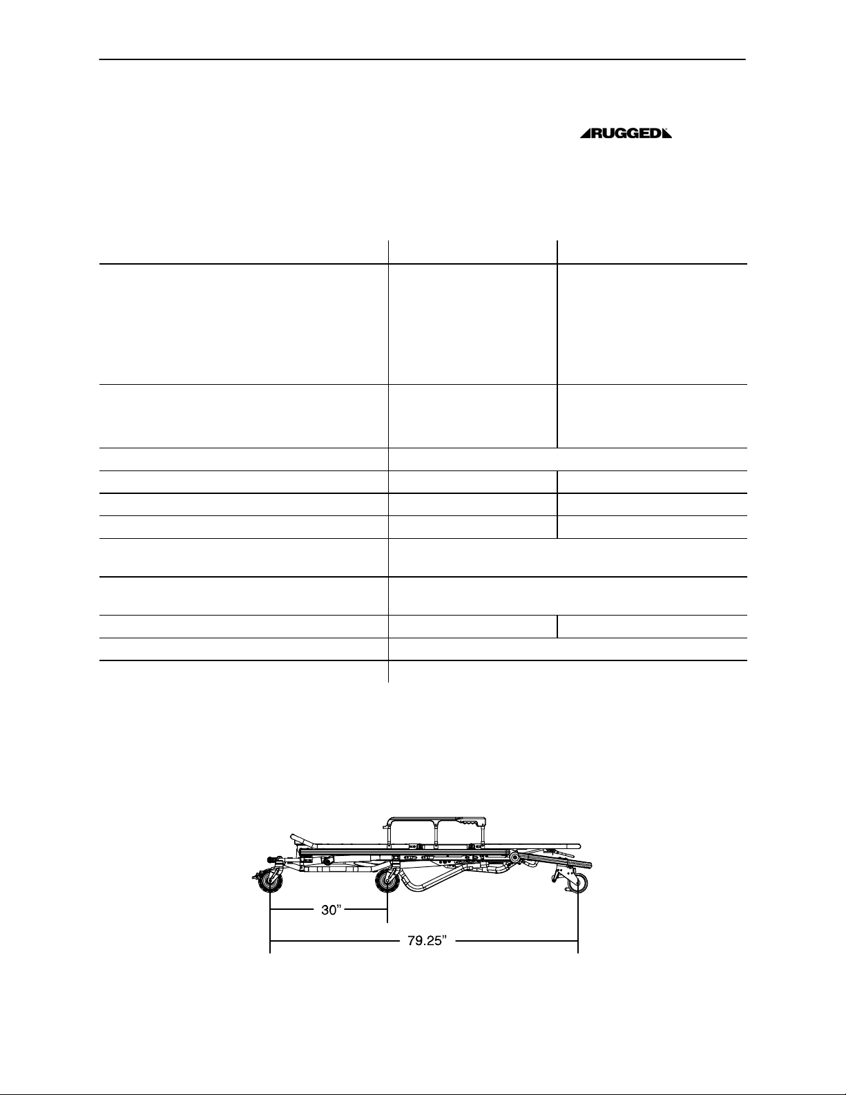
SPECIFICATIONS
Overall Length/Minimum Length/Width 83”/66”/23” 210.8cm / 167.6cm / 58.4cm
Height! − Position 1 (folded)
Position 2 (intermediate height)
Position 3 (intermediate height)
Position 4 (intermediate height)
Position 5 (loading)
(see page 14 for positions)
Patient Surface Fowler: 28.0”
Backrest Articulation/Shock Position 2_ to 73° / +14_
Weight@ 94 lbs 42.6 kg
Maximum Weight Capacity 650 pounds 294.8 kg
Caster Diameter/Width 6”/2” 15.2 cm / 5.1 cm
Minimum Operators Required for Loading/
Unloading an Occupied Cot
Recommended Fastener Systems Model 6370/6374/6377/6378 Floor Mount Type
Recommended Floor Height# Up to 32” Up to 81.2 cm
Roll−In Style Yes
Single Wheel Lock / Double Wheel Lock Optional
12.0” (−3 degrees)
22.0”
28.0”
32.0”
37.0”
30.4 cm
55.8 cm
71.1 cm
81.2 cm
93.9 cm
71.1 cm
Trendelenburg: 32.0”
Midesction: 14.0”
81.2 cm
35.5 cm
2
Model 6371/6375 Wall Mount Type
! Height measured from bottom of mattress at seat section to ground level.
@ Cot is weighed without mattress and restraints.
# Height limit kit is recommended for ambulance deck heights less than 30 inches (67 cm) − Stryker part number 6092−202−010.
Stryker reserves the right to change specifications without notice.
The EZ−PROr R4 is designed to conform to the Federal Specification for the Star−of−Life Ambulance KKK−A−1822.
Figure 1 − Cot Length
3
Page 6

Introduction
WARNING / CAUTION / NOTE DEFINITION
The words WARNING, CAUTION and NOTE carry special meanings and should be carefully reviewed.
WARNING
Alerts the reader about a situation, which if not avoided, could result in death or serious injury. It may also
describe potential serious adverse reactions and safety hazards.
CAUTION
Alerts the reader of a potentially hazardous situation, which if not avoided, may result in minor or moderate
injury to the user or patient or damage to the equipment or other property. This includes special care necessary for the safe and effective use of the device and the care necessary to avoid damage to a device that
may occur as a result of use or misuse.
NOTE
This provides special information to make maintenance easier or important instructions clearer.
4
Page 7
Warranty
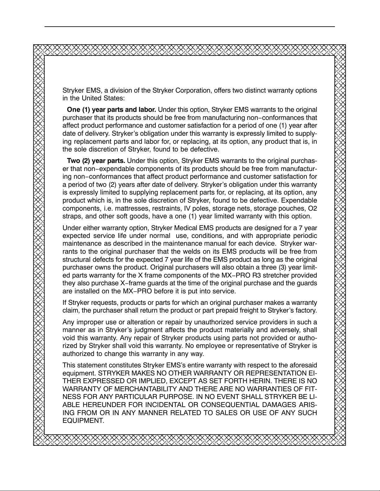
Stryker EMS, a division of the Stryker Corporation, offers two distinct warranty options
in the United States:
One (1) year parts and labor. Under this option, Stryker EMS warrants to the original
purchaser that its products should be free from manufacturing non−conformances that
affect product performance and customer satisfaction for a period of one (1) year after
date of delivery. Stryker’s obligation under this warranty is expressly limited to supply-
ing replacement parts and labor for, or replacing, at its option, any product that is, in
the sole discretion of Stryker, found to be defective.
Two (2) year parts. Under this option, Stryker EMS warrants to the original purchas-
er that non−expendable components of its products should be free from manufactur-
ing non−conformances that affect product performance and customer satisfaction for
a period of two (2) years after date of delivery. Stryker’s obligation under this warranty
is expressly limited to supplying replacement parts for, or replacing, at its option, any
product which is, in the sole discretion of Stryker, found to be defective. Expendable
components, i.e. mattresses, restraints, IV poles, storage nets, storage pouches, O2
straps, and other soft goods, have a one (1) year limited warranty with this option.
Under either warranty option, Stryker Medical EMS products are designed for a 7 year
expected service life under normal use, conditions, and with appropriate periodic
maintenance as described in the maintenance manual for each device. Stryker war-
rants to the original purchaser that the welds on its EMS products will be free from
structural defects for the expected 7 year life of the EMS product as long as the original
purchaser owns the product. Original purchasers will also obtain a three (3) year limit-
ed parts warranty for the X frame components of the MX−PRO R3 stretcher provided
they also purchase X−frame guards at the time of the original purchase and the guards
are installed on the MX−PRO before it is put into service.
If Stryker requests, products or parts for which an original purchaser makes a warranty
claim, the purchaser shall return the product or part prepaid freight to Stryker’s factory.
Any improper use or alteration or repair by unauthorized service providers in such a
manner as in Stryker’s judgment affects the product materially and adversely, shall
void this warranty. Any repair of Stryker products using parts not provided or autho-
rized by Stryker shall void this warranty. No employee or representative of Stryker is
authorized to change this warranty in any way.
This statement constitutes Stryker EMS’s entire warranty with respect to the aforesaid
equipment. STRYKER MAKES NO OTHER WARRANTY OR REPRESENTATION EI-
THER EXPRESSED OR IMPLIED, EXCEPT AS SET FORTH HERIN. THERE IS NO
WARRANTY OF MERCHANTABILITY AND THERE ARE NO WARRANTIES OF FIT-
NESS FOR ANY PARTICULAR PURPOSE. IN NO EVENT SHALL STRYKER BE LI-
ABLE HEREUNDER FOR INCIDENTAL OR CONSEQUENTIAL DAMAGES ARIS-
ING FROM OR IN ANY MANNER RELATED TO SALES OR USE OF ANY SUCH
EQUIPMENT.
5
Page 8

Warranty
Stryker EMS Return Policy
Cots, Stair Chairs, Evacuation Chairs, Cot Fasteners and Aftermarket Accessories:
may be returned up to 180 days of receipt if they meet the following guidelines:
Prior to 30 Days
S 30 day money back guarantee in effect
S Stryker EMS is responsible for all charges
S Returns will not be approved on modified items
Prior to 90 Days
S Product must be unused, undamaged and in the original packaging
S Customer is responsible for a 10% restocking fee
Prior to 180 Days
S Product must be unused, undamaged and in the original packaging
S Customer is responsible for a 25% restocking fee
Return Authorization:
Merchandise cannot be returned without approval from the Stryker Customer Service
Department. An authorization number will be provided which must be printed on the
returned merchandise. Stryker reserves the right to charge shipping and restocking
fees on returned items.
SPECIAL, MODIFIED, OR DISCONTINUED ITEMS NOT SUBJECT TO RETURN.
Damaged Merchandise:
ICC Regulations require that claims for damaged merchandise must be made with the
carrier within fifteen (15) days of receipt of merchandise. DO NOT ACCEPT DAM-
AGED SHIPMENTS UNLESS SUCH DAMAGE IS NOTED ON THE DELIVERY RE-
CEIPT AT THE TIME OF RECEIPT. Upon prompt notification, Stryker will file a freight
claim with the appropriate carrier for damages incurred. Claim will be limited in amount
to the actual replacement cost. In the event that this information is not received by
Stryker within the fifteen (15) day period following the delivery of the merchandise, or
the damage was not noted on the delivery receipt at the time of receipt, the customer
will be responsible for payment of the original invoice in full.
Claims for any short shipment must be made within thirty (30) days of invoice.
International Warranty Clause:
This warranty reflects U.S. domestic policy. Warranty outside the U.S. may vary by
country. Please contact your local Stryker Medical representative for additional infor-
mation.
Patent Information
Ruggedr Products are covered by one or more of the following patents:
United States 5,575,026 6,276,010 6,648,343 6,908,133 6,796,757
5,537,700 6,125,485 6,735,794 7,100,224 D527,103
Other Patents Pending
6
Page 9

Summary of Safety Precautions
The following is a list of safety precautions that must be observed when operating or servicing this unit. The
precautions are repeated throughout the manual, where applicable. Carefully read this list before using or
servicing the unit.
WARNING
S Improper usage of the Cot can cause injury to the patient or operator and/or damage to
the cot. Operate the cot only as described in this manual.
S Always use all restraint straps to secure the patient on the cot. An unrestrained or partially restrained
patient may fall from the cot and be injured.
S Siderails are not intended to serve as a patient restraint device. Refer to pages 17 & 18 for proper restraint
strap usage. Failure to use the siderails properly could result in patient injury or damage to the cot.
S Never leave a patient unattended on the cot or injury could result. Hold the cot securely while a patient
is on the cot.
S The wheel lock is only intended to help prevent the cot from rolling while unattended. The wheel lock may
not provide sufficient resistance on all surfaces or under loads.
S Never apply the optional wheel lock while a patient is on the cot. Tipping could occur if the cot is moved
while the wheel lock is applied, resulting in injury to the patient or operator and/or damage to the cot.
S Never install or use the wheel lock on a cot with excessively worn wheels. Installing or using the wheel
lock on a wheel with less than a 6” diameter could compromise the holding ability of the wheel lock, resulting in injury to the patient or operator and/or damage to the cot or other equipment.
S High obstacles such as curbing, steps or rough terrain can cause the cot to tip, possibly causing patient
or operator injury. If possible, obtain additional assistance (see page 31 for a reference chart) or take an
alternate route.
S Have the vehicle safety hook installed by a certified mechanic. Improper safety hook installation can
cause injury to the patient or operator and/or damage to the cot.
S Failure to install the safety hook can cause injury to the patient or operator. Install and use the safety
hook as described in this manual.
S To avoid injury, verify the safety bar has engaged the safety hook before removing the cot from the patient
compartment.
S The Cot must have at least 5/8 inch of clearance between the ambulance bumper and
the cot to disengage the safety bar when unloading the cot from the ambulance. Verify the legs lock into
the load position and visually inspect the lock pin (see page 30) before disengaging the safety bar from
the safety hook. Failure to properly lock the cot into position can cause injury to the patient and/or operator
or damage to the cot.
S When the optional head end storage pouch is being used, ensure the pouch does not interfere with the
operation of the safety bar and or safety hook. Injury to the patient or operator and/or damage to the cot
could occur.
S Loading, unloading and changing the position of the cot requires a minimum of two trained operators work-
ing together. The operator(s) must be able to lift the total weight of the patient, cot and any other items
on the cot. (If additional assistance is needed, see the reference chart on page 31).
S When changing the height of the cot, always verify the base frame is securely locked into position before
releasing your grip on the litter frame. Visually inspect the locking pin on the patient left side of the cot
to verify the lock pin is properly engaged (see page 30).
S To avoid injury, verify the has engaged the safety hook before removing the cot from the patient compart-
ment.
7
Page 10

Summary of Safety Precautions
WARNING
S Be sure the undercarriage has engaged and locked before removing the loading wheels from the patient
compartment floor of the vehicle.
S Always verify the base frame is securely locked into position before releasing your grip on the litter frame.
Visually inspect the locking pin on the patient left side of the cot to verify the lock pin is properly engaged
(see page 30). An unlocked base frame will not support the cot and injury to the patient or operator could
result.
S Unlock the auxiliary lock only to fold, change height position or load the cot. Improper use can cause injury
to the patient or operator.
S Practice folding, changing height position and loading the cot until operation of the auxiliary lock is fully
understood. Improper use can cause injury. Unlock the auxiliary lock only to fold, change height position
or load the cot.
S Do not allow untrained helpers to assist in the operation of the cot. Untrained technicians/helpers can
cause injury to the patient or themselves and/or damage to the cot.
S Do not step or ride on the base of the Cot. Damage to the cot could occur, resulting in
injury to the patient or operator.
S Failure to properly clean or dispose of contaminated mattress or cot components will increase the risk of
exposure to bloodborne pathogens and may cause injury to the patient or the operator.
S To avoid accidental release of the Pedi−Matet, and possible injury to the infant, ensure the buckle is lo-
cated away from obstructions on the cot or head end storage pouch.
S If the cot has an optional foot end oxygen bottle holder, hold the leg rest on the sides to avoid pinching
your hand between the cot frame and the oxygen bottle when lowering the leg rest.
S To avoid equipment damage and/or injury to the patient, remove all items from the optional base storage
tray before loading or lowering the cot.
S When necessary, modify the vehicle to fit the cot. Do not modify the Cot. Modifying the
cot can cause unpredictable operation resulting in injury to the patient or operator or damage to the cot.
Modifying the cot will also void its warranty.
S Damage to the cot can occur if the cot is lowered in the shortened position. Use only positions 2 − 5 (see
page 15) when the cot is shortened.
S Operating the cot with the breakaway head section lowered may cause injury to the patient or operator
or damage to the cot. Use only positions 4−5(see page 14) when using this configuration.
CAUTION
S Install the safety hook at least 1/8 inch from the edge of the rear ambulance door. After installation, verify
the cot legs lock into the load position without contacting the ambulance bumper.
S To properly engage the safety hook, a height limit kit is recommended for ambulance deck heights less
than 30 inches (76 cm) − Stryker part number 6092−202−010.
S Do not store items under the cot mattress. Storing items under the mattress can interfere with the opera-
tion of the cot.
S Do not steam clean, pressure wash, hose off or ultrasonically clean this unit. High pressure water
or steam can remove lubricants and cause corrosion. Clean the cot as described on page 37.
S To avoid damage, the weight of the I.V. bags should not exceed 40 pounds.
S Improper maintenance can cause injury to the patient or operator and/or damage to the unit. Maintain
the cot as described in this manual. Use only Stryker approved parts and maintenance procedures. Using
unapproved parts and procedures could cause unpredictable operation, damage to the cot and/or injury
and will void the product warranty.
S Failure to use authorized parts, lubricants, etc. could cause damage to the cot and will void the product’s
warranty.
8
Page 11

Setup Procedures
Unpack the cartons and check all items for proper operation. It is important that the Cot is
working properly before it is put into service. Have a qualified service person use the following list and the
operation instructions to check the cot before it is put into service.
S All fasteners secure (reference all assembly prints)
S All welds intact, not cracked or broken
S No bent or broken tubing or sheet metal
S No debris in wheels
S All wheels secure, rolling and swivelling properly
S Siderails move and latch properly
S Backrest operating properly
S Optional accessories intact and operating properly
S Height positioning latch functioning properly
S Auxiliary lock operating properly (see page 21)
S Cot secure in each height position
S Undercarriage folds properly
S Breakaway head section operating properly
S Lift capable safety bar operating properly
S Foot rest operating properly
S No rips or cracks in mattress cover
S Body restraints intact and working properly
S Wheel lock operating properly (optional equipment)
S Is there an approved crash−stable fastener (Stryker part number 6370/6374/6377/6378/6379 or
6371/6375 − not included) installed in the vehicle?
S Is there an approved vehicle safety hook (Stryker part number 6060−036−017, 6060−036−018 or
6092−036−018) installed in the vehicle?
The patient compartment of the vehicle in which the Cot will be used must have:
S A smooth rear edge for cot loading.
S A level floor large enough for the folded cot.
S Enough space to install the vehicle safety hook.
S Stryker 6370/6374/6377/6378/6379 or 6371/6375 crash stable cot fastener (not included).
S 32” (81 cm.) maximum loading height.
WARNING
To properly engage the safety hook, the height limiting option must be installed if the ambulance floor height
is less than 30 inches. If the option is not installed, damage to the cot could occur, resulting in injury to the
patient and/or operator.
When necessary, modify the vehicle to fit the cot. Do not modify the Cot. Modifying the cot
can cause unpredictable operation resulting in injury to the patient or operator or damage to the cot. Modifying
the cot will also void its warranty.
9
Page 12
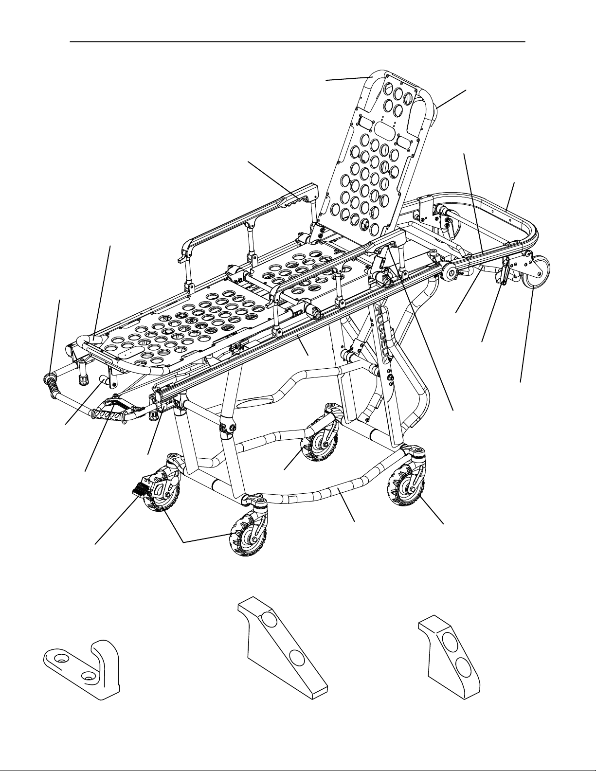
Component Identification
Foot End
Lifting Bar
Foot Rest
HEAD END
Siderail Release Handle
Litter Frame
Backrest
Backrest Adjustment
Release Handle
Breakaway
Head Section
Head End
Lifting Bar
Lift Capable
Safety Bar
Safety Bar
Release Lever
Foot Rest
Release
Handle
Auxiliary Lock
Foot End
Height Adjustment
Release Handle
Wheel Lock
(Optional)
Transport Wheels
J Safety Hook
Stryker part number
6092−036−018
Transport Wheels
Base Frame
Figure 2 − EZ−PROr R4
Long Safety Hook
Stryker part number
6060−036−018
Loading Wheels
(1 of 2)
Siderail Release Handle
Transport Wheels
Short Safety Hook
Stryker part number
6060−036−017
10
Page 13

Vehicle Safety Hook Installation
Ambulance Configuration
The vehicle safety hook is a device shipped with the cot. The safety bar and hook are designed to keep the
cot from being accidently removed from the ambulance and to provide increased operator assurance and
confidence when unloading. The vehicle safety hook was designed to ensure compatibility and proper operations of the cot during unloading when used in an ambulance vehicle compliant with Federal Regulation KKK−
A−1822.
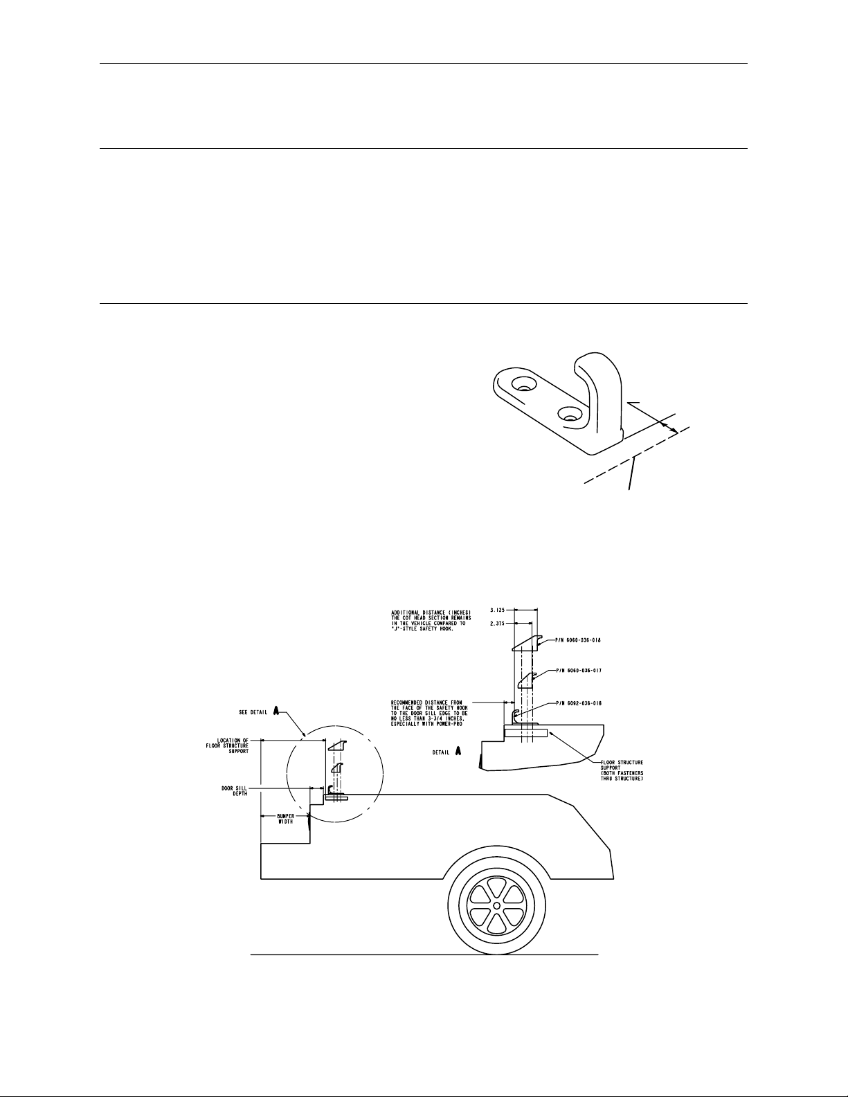
According to federal regulations (reference KKK−A−1822), the bumper height of the ambulance shall be
installed equidistant 2 inches (5 cm) from the ambulance floor to the ground level, defined as the ambulance
deck height (Figure 3). The bumper step shall have a minimum depth of 5 inches (13 cm) and a maximum
depth of 10 inches (25 cm). If the bumper length is greater than 7 inches (18 cm), then the bumper must be
able to fold. Installation of the safety hook into any ambulance vehicle compliant with this federal specification
will provide adequate clearance for the cot base to lower to its fully extended position (Figure 4). The cot is
compatible with all ambulance deck heights up to 32 inches as long as the ambulance meets the federal specifications outlined in KKK−A−1822.
DH
ǒ
Ǔ
" 2
2
Figure 3 − Ambulance Deck Height Figure 4 − Ambulance Deck Height
CAUTION
Height limit kit is recommended for ambulance deck heights less than 30 inches (76 cm) − Stryker part number
6092−202−010.
Installation of the safety hook should be done by a certified mechanic familiar with ambulance construction.
Consult the vehicle manufacturer before installing the safety hook and be sure the installation of the safety
hook does not damage or interfere with the brake lines, oxygen lines, fuel lines, fuel tank or electrical wiring
of the vehicle.
Required Hardware for Installation of the Safety Hook (Not Supplied)
(2) Grade 5, 1/4”−20 Socket Head Cap Screws *
(2) Grade 5, 1/4”−20 Flat Head Cap Screws *
(2) Flat Washers
(2) Lock Washers
(2) 1/4”−20 Nuts
* The length of the socket head cap screws depends on the thickness of the vehicle floor. Use screws long
enough to go completely through the patient compartment floor, washer and nut by at least two full threads.
11
Page 14
n
Vehicle Safety Hook Installation
Positioning and Installing the Safety Hook
WARNING
Have the vehicle safety hook installed by a certified mechanic. Improper safety hook insatllatino can cause
injury to the patient and/or operator or damage to the cot.
Failure to install the safety hook can cause injury to the patient or operator. Install and use the safety hook
as described in this manual.
Install the safety hook at least 1/8 inch from the edge of the rear ambulance door. After installation, verify
the cot legs lock into the load position without contacting the ambulance bumper.
To avoid injury, verify the safety bar has engaged the safety hook before removing the cot from the patient
compartment.
Note: Stryker recommends that, prior to installation, the certified mechanic plan the placement of the safety
hook in the rear of the vehicle.
Procedure:
1. Remove the cot from the fastener and unload it
from the vehicle.
2. While the cot is being removed, note the position of
the loading wheels and the safety bar.
3. Center the safety hook on the cot safety bar, with
the hook facing the front of the vehicle (Figure 5a).
For best results, the face of the safety hook which
engages the safety bar should be at least 3−3/4”
from the leading edge of the door sill (Figure 5b)
1/8 inch
(reference only)
Inside Edge of Rear Doors
(When Closed)
Figure 5a − Safety Hook Placement
Figure 5b Safety Hook Placement
12
Page 15
n
Vehicle Safety Hook Installation
Positioning and Installing the Safety Hook (Continued)
4. Mark the position of the safety hook on the patient compartment floor. The safety hook should be installed
as close as possible to the rear of the vehicle while allowing the vehicle doors to close and checking that
the load wheels always remain on the patient compartment floor (i.e. wheels do not roll off the door sill
when the cot safety bar engages the safety hook) when the cot is loaded and unloaded from road and/or
curb height (Figure 6).
5. Ensure the bumper and bumper step do not interfere with the operation of the cot.
6. Drill the holes for the socket head cap screws.
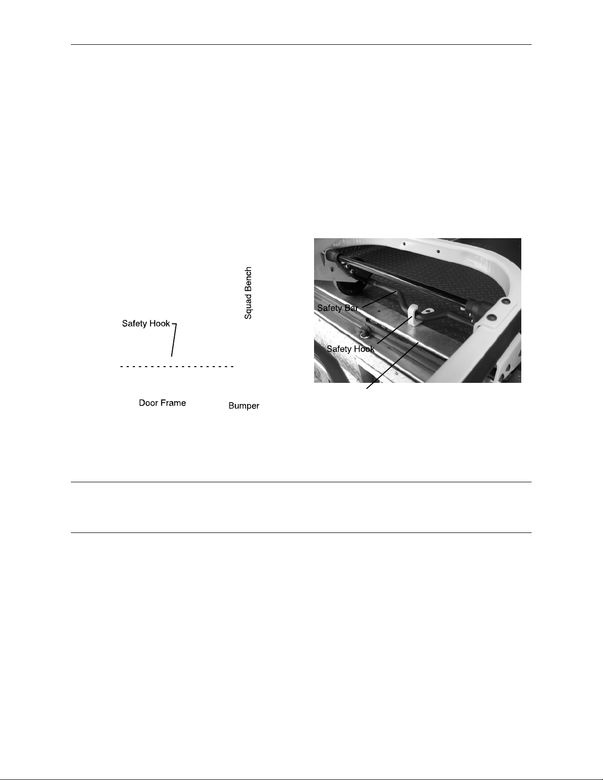
7. Fasten the safety hook to the patient compartment floor and verify that the safety hook always engages
the cot safety bar when the cot is unloaded from the vehicle (Figure 7).
Top View of Vehicle
Floor Edge
Figure 6 − Safety Hook Placement
Figure 7 − Safety Bar Engaging Safety Hook
WARNING
The cot must have at least 5/8” of clearance between the ambulance bumper and the cot to disengage the
safety bar when unloading the cot from the ambulance. Failure to properly lock the cot into position can cause
injury to the patient or operator and/or damage to the cot.
13
Page 16
Cot Positions
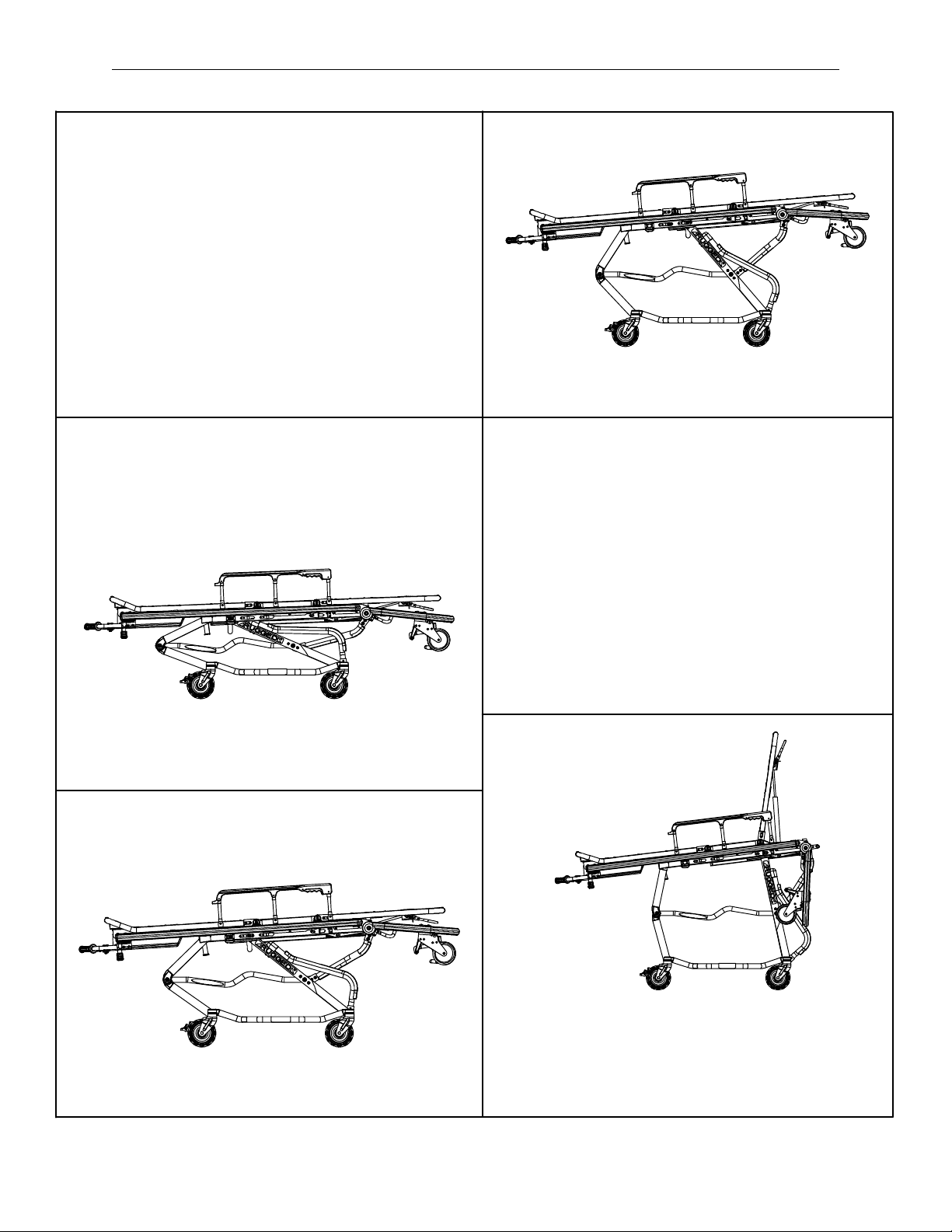
Position 1 − Folded Position − Use for patient
transfer and transporting in an ambulance.
Position 2 − Intermediate Height Position
Use for patient transfer/cot rolling.
Position 4 − Intermediate Height Position
Use for patient transfer/cot rolling.
Position 5 − Loading Position
Use for patient transfer/cot rolling,
folding or loading the cot.
Position 3 − Intermediate Height Position
Use for patient transfer/cot rolling.
Warning − Operating the cot with the breakaway
head section lowered may cause injury to the patient
or operator or damage to the cot. Use only positions
4−5 when using this configuration.
14
Page 17

Cot User Tips
Disengaging the auxiliary lock
The auxiliary lock must always be disengaged to lower the cot from the load position or to load the cot into
the ambulance. It is located at the foot end of the cot on patient’s left side. Push the lock lever towards the
head end to disengage the auxiliary lock.
Auxiliary lock resets automatically
The auxiliary lock automatically resets after the red release handle is squeezed and released. If this occurs
while the cot is still in the load (or highest) position, you must disengage the auxiliary lock again before loading
or lowering the cot.
Auxiliary lock only locks in the load position
When the cot is in any position other than the load position (highest position), there is no need to disengage
the auxiliary lock.
Built in safety feature (lift then squeeze)
The cot has a built in safety feature which requires both operators to lift the cot slightly before the foot
end operator squeezes the red foot−end release handle. This feature ensures both operators are pre-
pared to lower the cot and decreases the chance of injury to the operators and/or patient. With an empty cot,
the operators may have to generate a downward force after squeezing the foot end release handle to start
the cot on its downward descent.
Squeeze foot−end release completely
After raising the cot slightly from both ends, squeeze the foot end release handle all the way to the grip
to begin lowering the cot. Relaxing your grip on the handle once the cot starts downward allows the cot to
lock in any of the height positions. When raising the cot to a higher position, completely squeeze the foot
end release handle.
Transport at load−height position
You may transport the cot in the load height position. This eliminates the need for changing the height of the
cot prior to loading the cot into the vehicle. Note: Transport in the lowest height position appropriate to ensure
patient safety.
Cot is not flat in highest transport position
The cot litter is at a slight head−up/foot−down angle (reverse Trendelenburg) when it is in its highest transport
position to facilitate easy loading.
Unloading from Ambulance
It is not necessary to squeeze the foot end release handle when lowering the cot out of the ambulance.
One−step cot positioning
You can raise the cot from any position to the load position in one step.
15
Page 18
Cot Operation
Using Restraint Straps
WARNING
Always use all restraint straps to secure the patient
on the cot. An unrestrained or partially restrained
patient may fall from the cot and be injured.
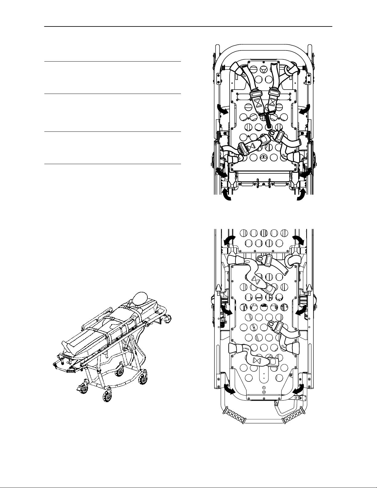
Always secure the patient on the cot with all the restraint straps. Buckle the restraints across the patient’s chest/shoulders, waist and legs (Figure 8).
WARNING
Never leave a patient unattended on the cot or injury
could result. Hold the cot securely while a patient
is on the cot.
When attaching the restraint straps to the cot, keep
in mind the attachment points should provide strong
anchorage and proper restraint position while not interfering with equipment and accessories. Wrap
the strap around the cot frame and back through the
loop on the end of the strap as shown in Figures 9
and 10. The arrows indicate alternate attachment
areas.
Figure 9 − Head Section Restraints
Keep the restraint straps buckled when the cot is not
being used with a patient to avoid damage to the
buckles and straps.
For Pedi−Matet restraint instructions see page 18
and 19.
Figure 8 − Patient Restrained on EZ−PROr R4
16
Figure 10 − Foot Section Restraints
Page 19
Cot Operation
Using Restraint Straps (Continued)
C
C
A
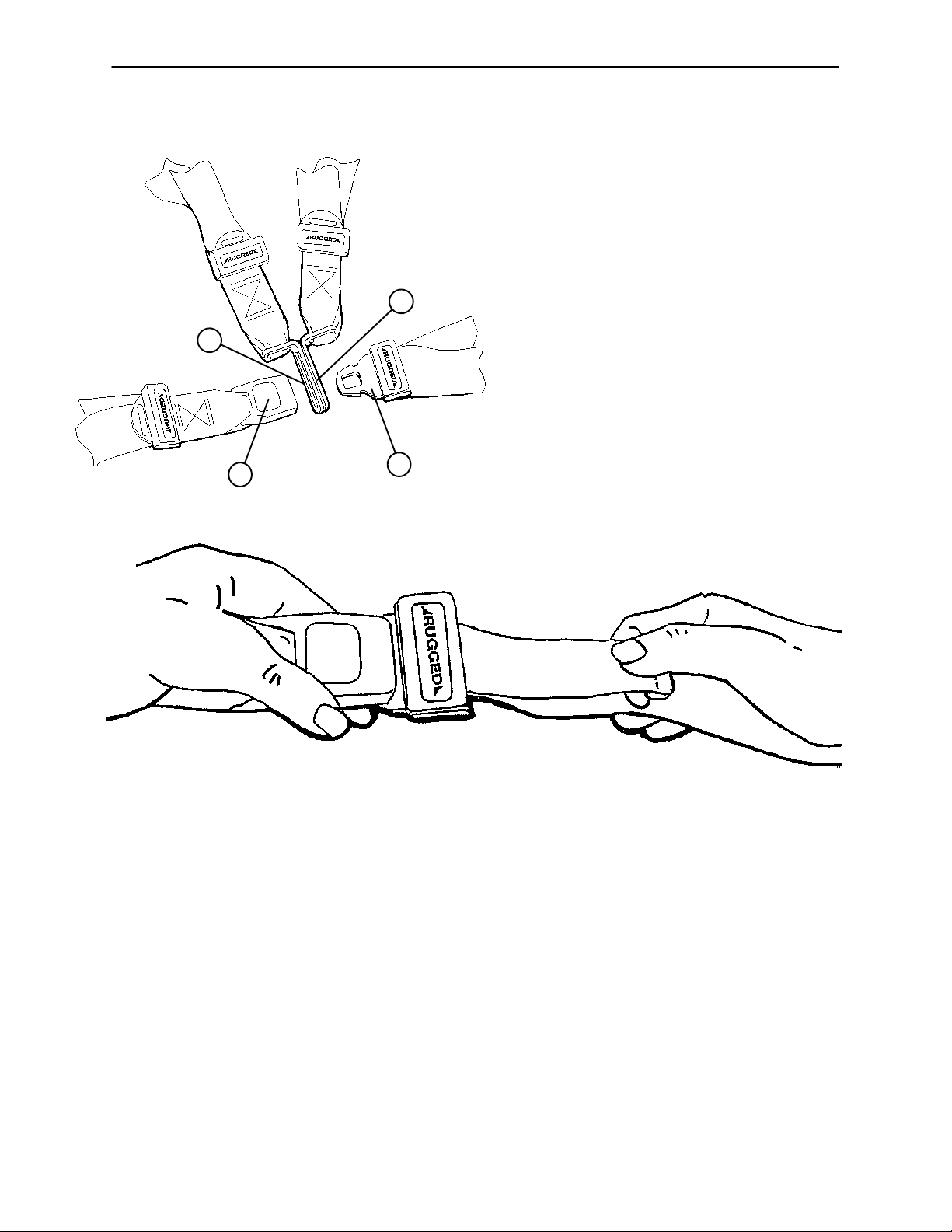
Figure 11 − Buckling the Restraints
When the cot is put into service, the restraints are opened and placed to either side of the cot until the patient
is positioned on the cot mattress. The restraint is lengthened, buckled around the patient and shortened until
the required tightness is achieved.
To open the restraint, press the red button (A) on the front of the buckle ”receiver”. This releases the buckle
”tang” (B) which can then be pulled out of the receiver (Figure 11).
To close the restraint, push the tang into the receiver until a ”click” is heard. When fastening the chest restraint
be sure the tang passes through both links (C) on the shoulder strap (Figure 11).
B
Figure 12 − Lengthening the Safety Restraints
Figure 13 − Tightening the Safety Restraint
To lengthen the restraint, grasp the buckle tang, turn it at an angle to the webbing, then pull out (Figure 12).
A hemmed tab at the end of the webbing prevents the tang from coming off the strap.
To shorten the restraint, grasp the hemmed tab and pull the webbing back through the tang until the required
tightness is achieved (Figure 13).
Whenever a restraint is buckled on a patient, the attendant should verify the tang is fully engaged and the
extra webbing is not tangled in the cot or hanging loose.
Inspection of the restraints should be done at least once a month (more frequently if used heavily). Inspection
should include checking for a bent or broken receiver or tang, torn or frayed webbing, etc. Any restraint showing wear or not operating properly must be replaced immediately.
17
Page 20

Pedi−Matet Infant Restraint System Attachment Instructions
Refer to the Pedi−Matet users manual for the manufacturer’s recommendations for the use, operation and
care of the Pedi−Matet Infant Restraint System.
Securing the Pedi−Matet to the cot
1. Remove any restraints already attached to the cot.
2. Raise the cot backrest to the full upright position.
3. Position the Pedi−Matet pad flat on the backrest with the black backrest straps out (Figure 14).
Figure 14 − Positioning the Pedi−Matet
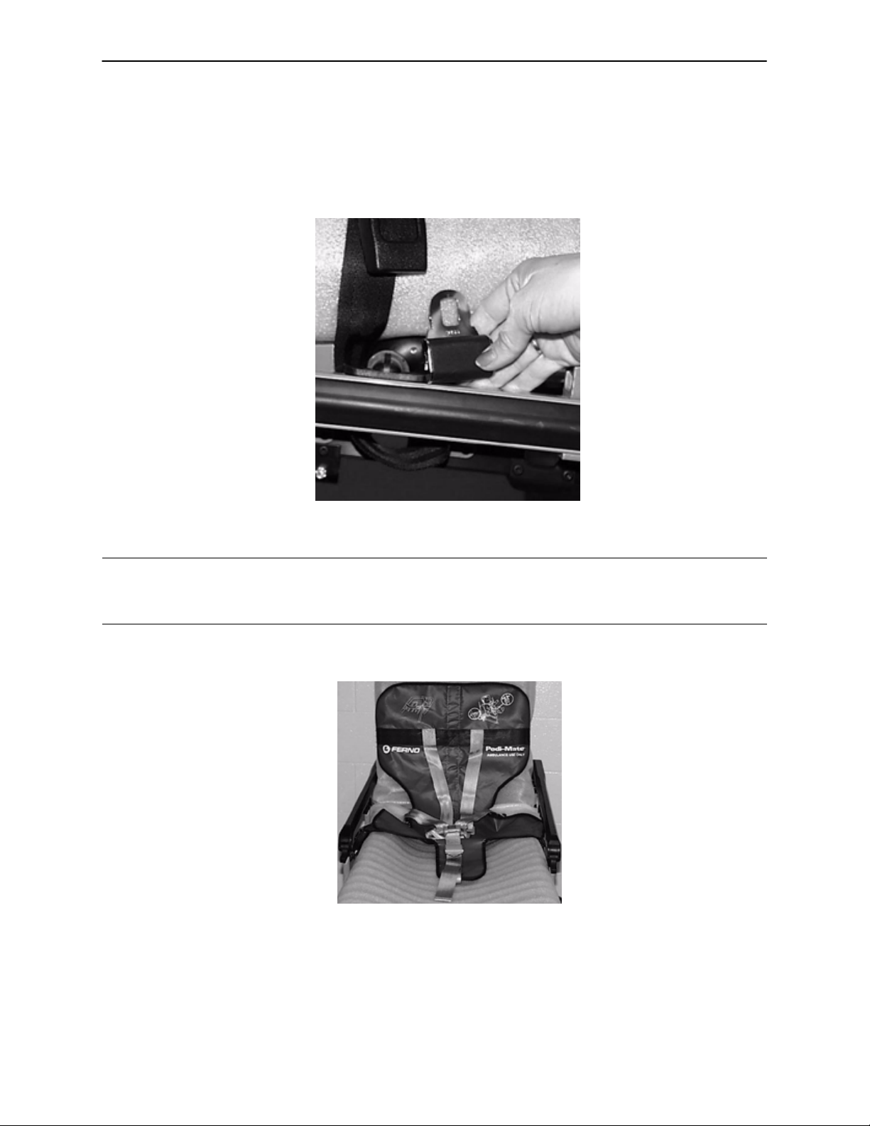
4. Wrap the straps around the backrest and insert the ends of the straps through the brackets. Securely
fasten the buckle (Figure 15).
Figure 15 − Fastening the Pedi−Matet Buckle
WARNING
To avoid accidental release of the Pedi−Matet, and possible injury to the infant, ensure the buckle is located
away from obstructions on the cot or head end storage pouch.
18
Page 21
Pedi−Matet Infant Restraint System Attachment Instructions
5. Pull firmly on the end of the adjustable backrest strap and tighten it securely.
6. Insert the mainframe straps between the cot frame and the mattress. To ensure the release button is
toward the foot end of the cot, insert the buckle behind the litter crossbrace and bring it up in front of the
crossbrace. Secure the buckle around the crossbrace, leaving a little slack in the strap for final adjustment (see Figure 16).
Figure 16 − Securing the Safety Restraints on a RuggedrCot
WARNING
To avoid accidental release of the Pedi−Matet, and possible injury to the infant, ensure the buckle is located
away from obstructions on the cot.
7. Verify all the straps are snug and fastened securely (Figure 17).
Figure 17 − Pedi−Matet Strapped to a Ruggedr Cot
These are general instructions for installation of the Pedi−Matet. Safe and proper use of the Pedi−Matet is solely at
the discretion of the user. Stryker recommends all users be trained on the proper use of the Pedi−Matet before using it
in an actual situation.
Retain these instructions for future reference. Include them with the product in the event of transfer to new users.
Pedi−Matet is a trademark of Ferno−Washington Inc.
19
Page 22
Cot Operation
Guidelines for Operation
S Use the Cot only as described in this manual.
S Read and understand all labels and instructions on the cot before using the cot.
S Use a minimum of two operators to manipulate the cot. (If additional assistance is required, see page 31
for a reference chart).
S Do not adjust, roll or load the cot without advising the patient. Stay with the patient and control the cot
at all times.
S Always use the restraint straps and keep the siderails up when a patient is on the cot.
S Use properly trained helpers when necessary to control the cot and patient.
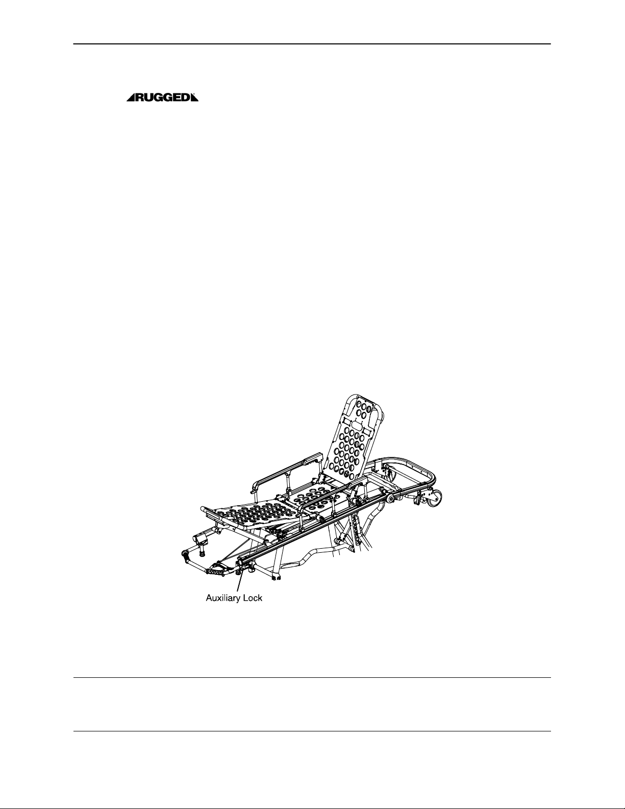
Auxiliary Lock
The auxiliary lock keeps the base frame from inadvertently exiting the loading position. Unlock the auxiliary
lock when:
S going from the loading position to the folded position,
S going from the loading position to an intermediate height position,
S loading the cot into the ambulance.
Procedure
1. Put the cot in the loading position (see page 15).
2. Move the auxiliary lock lever to the right to the unlocked position.
3. Lower, change height position or load the cot.
Figure 18 − Auxiliary Lock
NOTE
The auxiliary lock can be unlocked only when the cot is in the loading position.
The auxiliary lock will reset to the locked position once the foot end release handle is actuated.
WARNING
Practice folding, changing height position and loading the cot until operation of the auxiliary lock is fully understood. Improper use can cause injury. Unlock the auxiliary lock only to fold, change height position or load
the cot.
20
Page 23
Cot Operation
TRANSFERRING THE PATIENT TO THE COT
1. Roll the cot to the patient.
2. Place the cot beside the patient and raise/lower the cot to
the patient’s level.
3. Lower the siderails and open the restraint
straps.
4. Transfer the patient to the cot using accepted EMS procedures.
5. Use all the restraints to secure the patient to
the cot (see pages 16 & 17 for restraint
strap usage instructions).
6. Raise the siderails and adjust the backrest and
leg rest as necessary.
Figure 19 − Transferring the Patient to the Cot
WARNING
Always use all restraint straps to secure the patient on the cot. An unrestrained or partially restrained patient
may fall from the cot and be injured.
Never apply the optional wheel lock while a patient is on the cot. Tipping could occur if the cot is moved while
the wheel lock is applied, resulting in injury to the patient or operator and/or damage to the cot.
ROLLING THE COT
1. Make sure all the restraint straps are securely
buckled around the patient (see pages 16 & 17 for
restraint strap usage instructions).
2. Place the cot in positions 2−5 for rolling (see page
14 for cot positions).
3. When rolling the cot, position an operator at the foot
end and one at the head end or the side at all times.
(If additional assistance is needed, see the reference chart on page 31).
4. During transport, approach door sills or other low
obstacles squarely and lift each set of wheels over
the obstacle separately.
Figure 20 − Rolling the Cot
WARNING
High obstacles such as curbing, steps or rough terrain can cause the cot to tip, possibly causing patient or
operator injury. If possible, obtain additional assistance (see page 31 for a reference chart) or take an alternate route.
Operating the Cot with the breakaway head section lowered may cause injury to the patient or operator or
damage to the cot. Use only positions 4−5 (see page 14) when using this configuration
21
Page 24
Cot Operation
CHANGING COT HEIGHT
WARNING
Loading, unloading and changing the position of the cot requires a minimum of two trained operators working
together. The operator(s) must be able to lift the total weight of the patient, cot and any other items on the
cot. (If additional assistance is needed, see the reference chart on page 30).
When changing the height of the cot, always verify the base frame is securely locked into position before releasing your grip on the litter frame. Visually inspect the locking pin on the patient left side of the cot to verify
the lock pin is engaged (see page 29).
Do not step or ride on the base of the Cot. Damage to the cot could occur, resulting in injury
to the patient or operator.
The EZ−PROr R4 has five height positions (see page 14):
S The highest or loading position,
S three intermediate Transport positions,
S a “Folded” position.
CHANGING BETWEEN LOADING AND FOLDED POSITIONS:
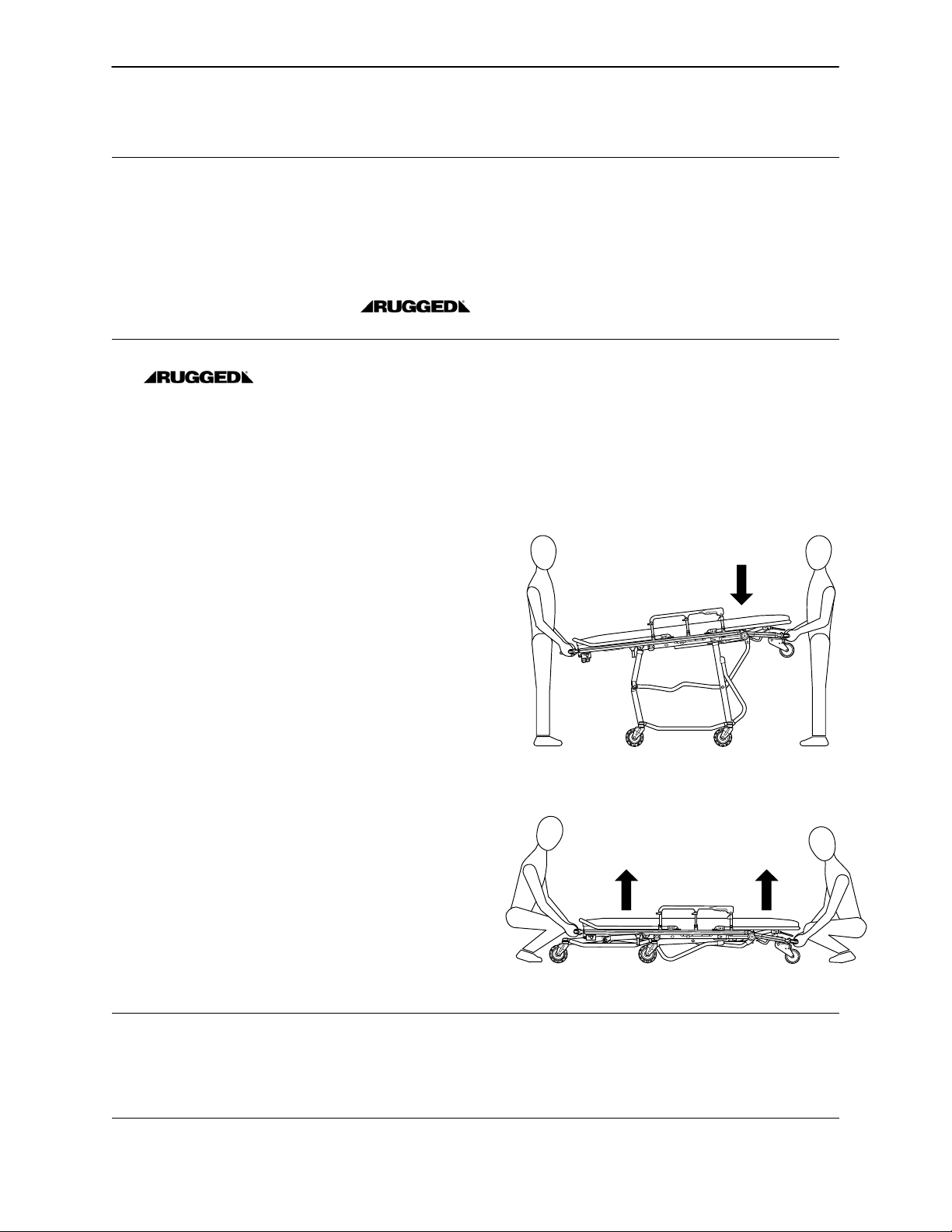
Changing From the Loading to the Folded Position:
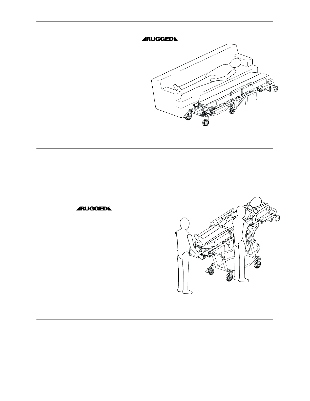
1. To lower the cot from its loading position to its folded
position, two operators stand at opposite ends of the
cot and grasp the litter frame with palms facing up (as
shown in Figure 21).
2. The foot end operator unlocks the cot’s auxiliary lock,
located at the foot end on the patient’s left side. (The
auxiliary lock provides added security to help prevent
inadvertent drops.)
3. Both operators lift the cot until the weight is off the
latching mechanism (approximately 1/4”).
4. The foot end operator squeezes and holds the release handle and both operators lower the cot to the
folded position.
NOTE
The auxiliary lock resets automatically when the foot end
height adjustment release handle is activated.
Changing From the Folded to the Loading Position:
To raise the cot to its loading position, two operators
grasp both ends of the litter frame and raise the cot until
the base frame has locked into place (as shown in Figure 22).
Figure 21 − Lowering the Cot to the Folded Position
Figure 22 − Raising the Cot to the Loading Position
WARNING
Always verify the base frame is securely locked into position before releasing your grip on the litter frame.
Visually inspect the locking pin on the patient left side of the cot to verify the lock pin is properly engaged
(see page 29). An unlocked base frame will not support the cot and injury to the patient or operator could
result.
22
Page 25
Cot Operation
CHANGING COT HEIGHT (CONTINUED)
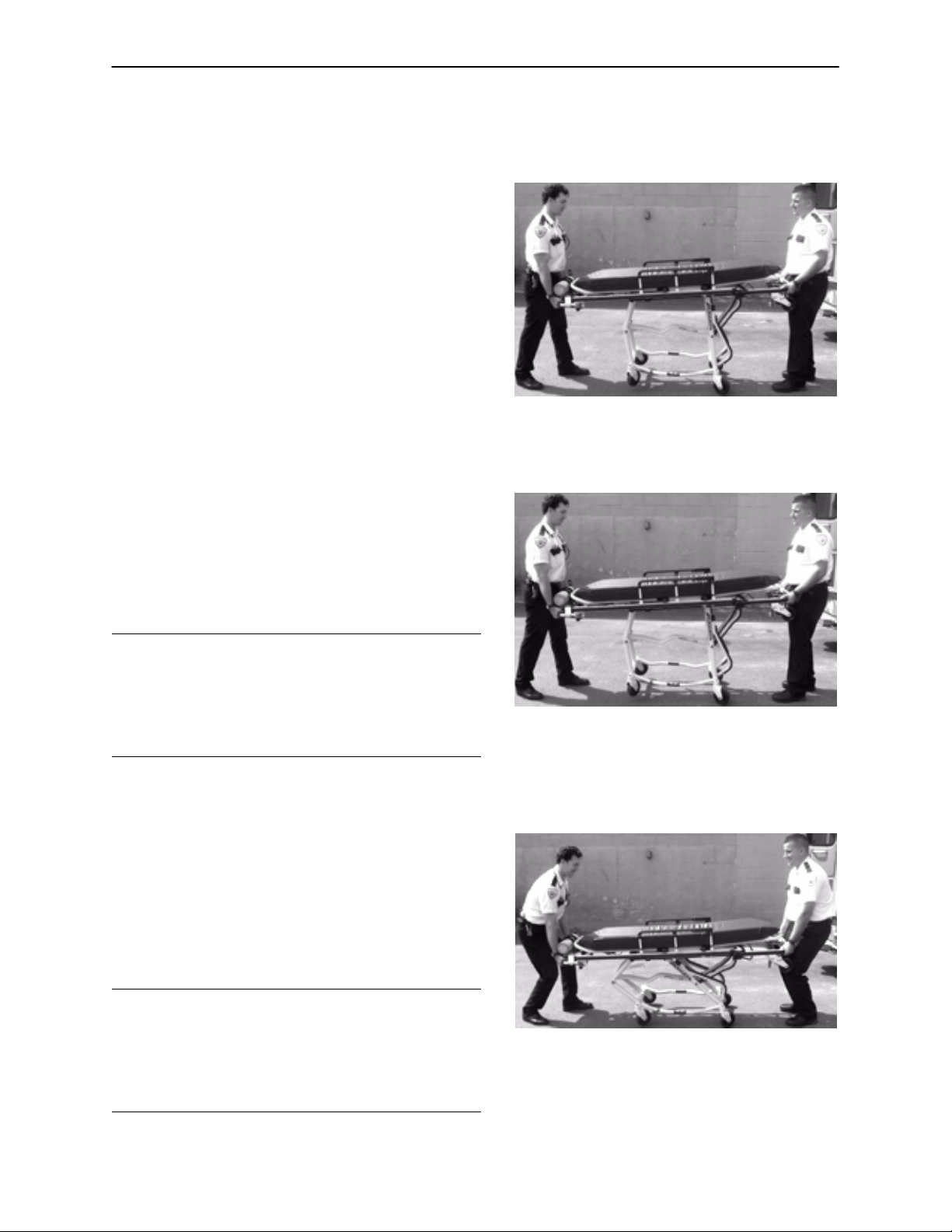
Lowering the Cot from the Load Position to an Intermediate Transport Position:
1. Two operators firmly grasp the litter frame at opposite ends with their palms facing up (Figure 23).
2. The foot end operator unlocks the auxiliary lock.
3. Both operators lift the cot until the weight is off the
latching mechanism (approximately 1/4”).
4. The foot end operator squeezes and holds the release handle and both operators lower the cot to
the folded position.
5. As downward motion of the cot begins, the operator at the foot end relaxes his/her grip on the re-
lease handle to stop the cot in the first intermediate
transport position.
Raising the Cot from an Intermediate Transport Position to the Load Position:
1. Two operators firmly grasp the litter frame at opposite ends with palms facing up.
Figure 23 − Lowering the Cot to the
Intermediate Position
2. Both operators lift slightly to take the weight off the
base frame (approximately 1/4”).
3. The foot end operator squeezes and holds the release handle and both operators lift the cot to the
loading position.
WARNING
Always verify the base frame is securely locked into
position before releasing your grip on the litter frame.
Visually inspect the locking pin on the patient left side
of the cot to verify the lock pin is properly engaged (see
page 29).
Figure 24 − Raising the Cot from the
Changing Between Two Intermediate Transport Positions:
1. Two operators firmly grasp the litter frame at opposite ends with palms facing up.
2. Both operators lift slightly (approximately 1/4”) to
take the weight off the base frame.
3. The foot end operator squeezes the release handle. As upward or downward motion begins, the
foot end operator relaxes his/her grip on the re-
lease handle to stop in the desired position.
Intermediate Position
WARNING
Always verify the base frame is securely locked into
position before releasing your grip on the litter frame.
Visually inspect the locking pin on the patient left side
of the cot to verify the lock pin is properly engaged (see
page 29).
23
Figure 25 − Changing Cot Height Between
Intermediate Positions
Page 26
Cot Operation
CHANGING COT HEIGHT (CONTINUED)
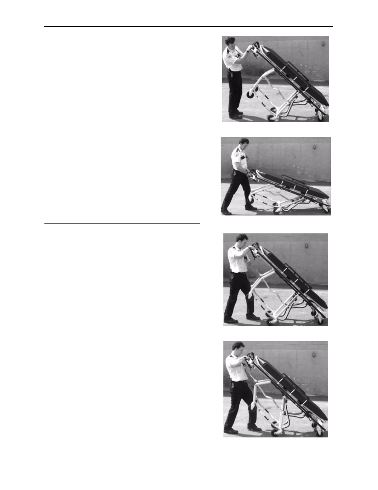
Changing Between the Loading and the Folded
Position with One Operator and an Empty Cot
When a cot is empty, one trained operator can fold the cot
or put it into the loading position.
Changing From the Loading to the Folded Position:
1. Stand at the foot end of the cot and lift the foot end so
the loading wheels on the breakaway head section
touch the floor (Figure 26).
2. Unlock the auxiliary lock.
3. Squeeze the foot end height adjustment release handle.
4. Lower the cot to the folded position.
Changing From the Folded to the Loading Position:
1. Grasp the foot end firmly.
2. Lift until the base frame securely locks into place (Figure 27).
WARNING
Always verify the base frame is securely locked into position before releasing your grip on the litter frame. Visually
inspect the locking pin on the patient left side of the cot to
verify the lock pin is properly engaged (see page 29). An
unlocked base frame will not support the cot and injury to
the patient or operator could result.
Changing Between a Loading and an Intermediate
Position with One Operator and an Empty Cot
Figure 26 − Folding the Cot with 1 Operator
Figure 27 − Raising the Cot to Load
Height with 1 Operator
1. Stand at the foot end of the cot and lift the foot end so
the loading wheels on the breakaway head section
touch the floor (Figure 28).
2. Unlock the auxiliary lock.
3. Brace the base of the cot against your body and put
one hand on the crossbrace.
4. Squeeze the foot end height adjustment release handle.
5. Pull the crossbrace toward your body until the cot locks
into the desired position (Figure 29).
6. Tip the cot back onto its four wheels in the rolling position.
24
Figure 28 − Tip the Cot onto Load Wheels
Figure 29 − Lower to Intermediate Position
Page 27
Cot Operation
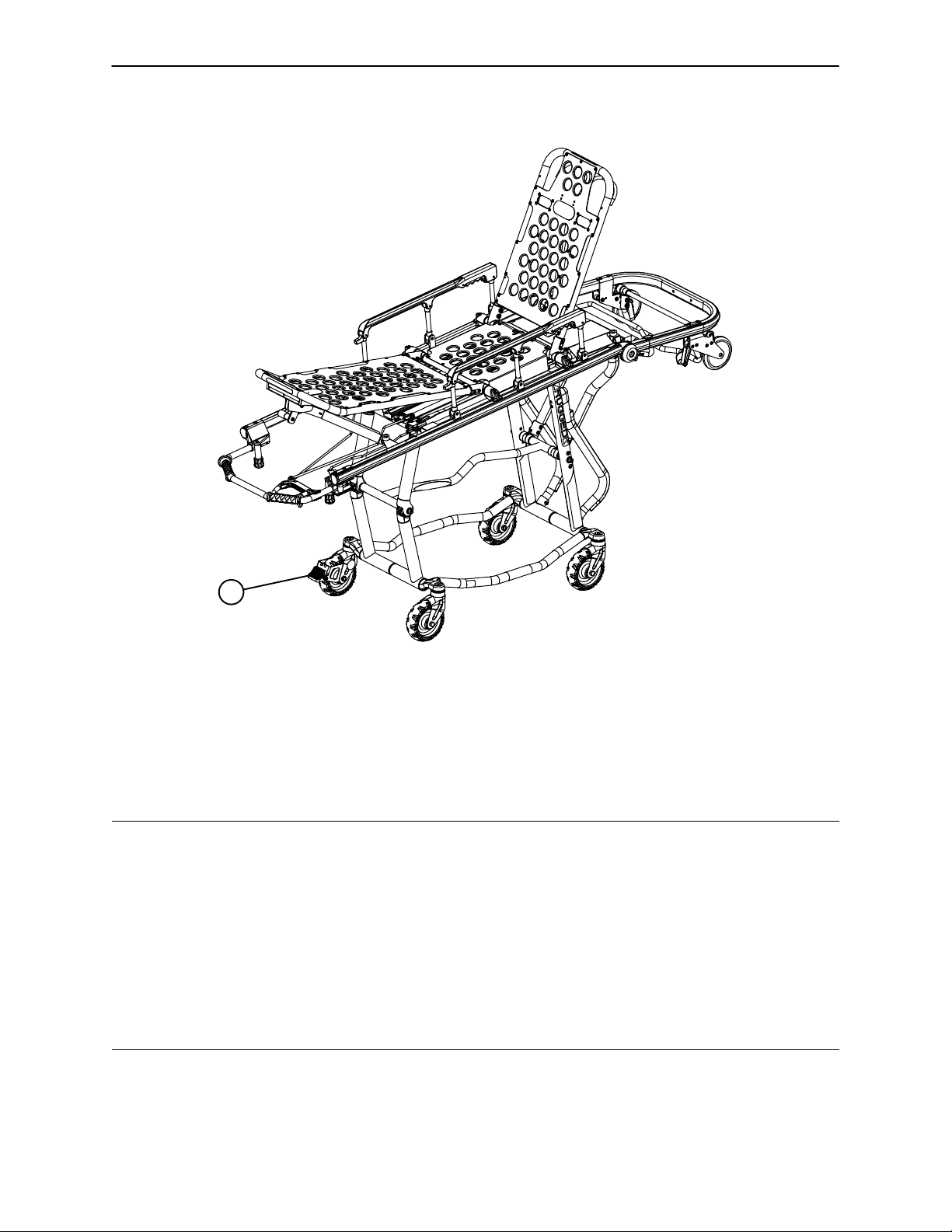
OPERATING THE OPTIONAL WHEEL LOCK
A
Figure 30 − Optional Wheel Lock
1. To activate the optional wheel lock, press fully down on the pedal (A) until it stops.
2. To release the optional wheel lock, depress the upper face of the wheel lock pedal with your foot or lift
up with your toe under the pedal. The upper portion of the pedal will rest against the caster frame when
the wheel lock is released.
WARNING
Never apply the optional wheel lock while a patient is on the cot. Tipping could occur if the cot is moved while
the wheel lock is applied, resulting in injury to the patient or operator and/or damage to the cot.
The wheel lock is only intended to help prevent the cot from rolling while unattended. The wheel lock may
not provide sufficient resistance on all surfaces or under loads.
Never leave a patient unattended on the cot or injury could result. Hold the cot securely while a patient is
on the cot.
Never install or use the wheel lock on a cot with excessively worn wheels. Installing or using the wheel lock
on a wheel with less than a 6” diameter could compromise the holding ability of the wheel lock, possibly resulting in injury to the patient or operator and/or damage to the cot or other equipment.
25
Page 28
Cot Operation
ADJUSTING THE WHEEL LOCKING FORCE
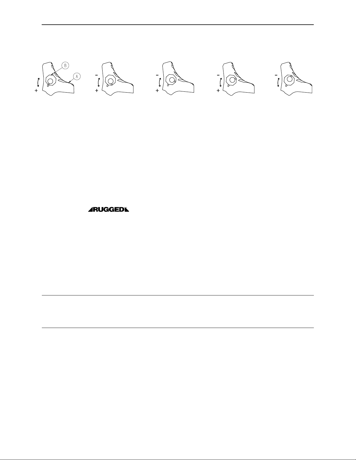
MINIMUM MAXIMUM
Figure 31 − Optional Wheel Lock Force Adjustment
1. To adjust the wheel locking force, remove the hex socket screw from the center of the lock pedal. The
wheel lock is initially assembled with the pedal set at the minimum locking force. The marker on the pedal
(item A) is aligned with the marker on the octagonal sleeve (item B).
2. Remove the sleeve (B). Rotate the sleeve counterclockwise to increase the pedal locking force and
clockwise to decrease the locking force. Insert the sleeve into the pedal. Reinstall the hex socket screw.
3. Test the pedal locking force before returning the cot to service.
LOADING THE COT INTO A VEHICLE
When loading the cot into a vehicle, an operator should remember the following important information:
S The higher the operator must lift the cot, the more difficult it becomes to hold the weight. The operator
may need help loading the cot into a vehicle if he/she is too short or if the patient is too heavy for the operator to lift safely. The operator should only lift the cot to a horizontal position when loading the cot. (If additional assistance is needed, see the reference chart on page 30).
S The operator must be able to lift the cot high enough for the cot’s base frame to unfold completely and
lock when the cot is unloaded. A shorter operator will have to raise his/her arms higher to enable the base
frame to unfold. (If additional assistance is needed, see the reference chart on page 30).
WARNING
Loading, unloading and changing the position of the cot requires a minimum of two trained operators working
together. The operator(s) must be able to lift the total weight of the patient, cot and any other items on the
cot. (If additional assistance is needed, see the reference chart on page 30).
26
Page 29
Cot Operation
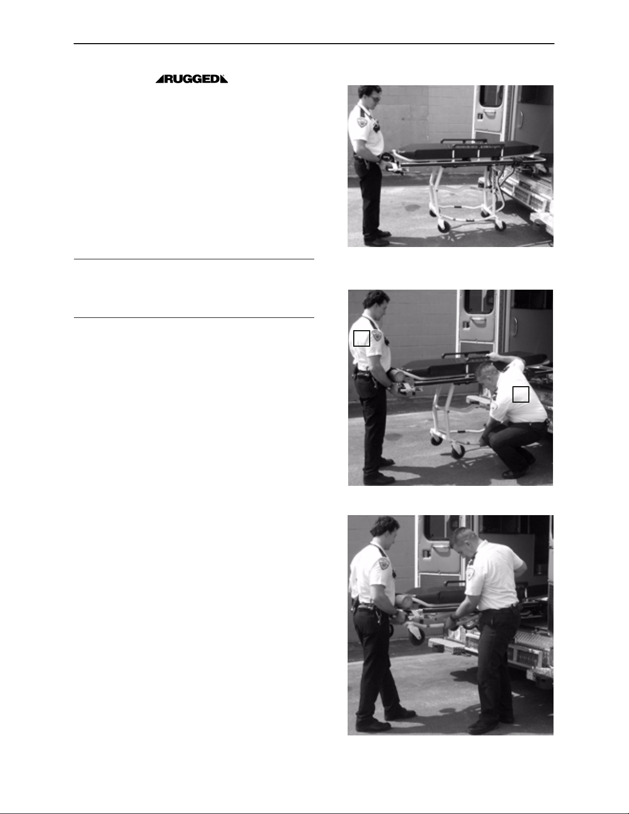
LOADING THE COT INTO A
VEHICLE (CONTINUED)
1. Place the cot in the loading position (see page 15).
2. Roll the cot to the open door of the patient
compartment, approaching the vehicle squarely.
3. Fold the vehicle bumper to the raised position (if
available).
4. Push the cot forward until both loading wheels are
on the patient compartment floor and the safety
bar passes the safety hook.
5. Operator 1 − Release the auxiliary lock.
WARNING
Unlock the auxiliary lock only to fold, change height
position or load the cot. Improper use can cause injury
to the patient or operator.
6. Operator 1 − Grasp and support the cot litter frame
at the foot end using an underhand grip.
7. Operator 1 − Lift the foot end of the cot until the
transport wheels are off the ground and the cot is
horizontal (Figure 32). Squeeze and hold the foot
end release handle and push the cot into the vehicle.
8. Operator 2 − As Operator 1 pushes the cot into the
vehicle, lift on the base frame to help the base
frame fold as the cot loads into the vehicle (Figure
33).
9. Both operators − Push the cot into the patient
compartment (Figure 34), engaging the cot fastener (not included).
10. Operator 1 − Let go of the foot end release handle.
NOTE
Loose items or debris on the patient compartment floor
can interfere with the smooth rolling of the cot and the
operation of the cot fastener. Keep the patient
compartment floor clear.
Figure 32 − Lift Cot Horizontal, Lifting the
Wheels Off the Ground
1.
2.
Figure 33 − Folding the Base Frame
IMPORTANT NOTE
To recover from a loading attempt halted by the auxiliary lock, do the following:
1. Release the foot end release handle.
2. Be sure the auxiliary lock is in the locked position.
3. Return the cot to its transport wheels, and verify
the base frame is securely locked into position.
4. Retry the folding or loading procedure.
27
Figure 34 − Loading the Ruggedr Cot
Page 30

Cot Operation
UNLOADING THE COT FROM A VEHICLE
WARNING
Loading, unloading and changing the position of the cot requires a minimum of two trained operators working
together. The operator(s) must be able to lift the total weight of the patient, cot and any other items on the
cot. If additional assistance is needed, see the reference chart on page 30).
Disengage the cot from the cot fastener.
Operator 1 − Grasp the foot end of the cot frame using an underhand grip. Pull the cot from the patient
compartment. As the cot is pulled out of the patient compartment, the base frame unfolds and the safety bar
catches the safety hook. The Operator must keep the foot end of the cot high enough for the base frame
to unfold completely and lock into place before the transport wheels make contact with the ground.
WARNING
To avoid injury, verify the safety bar has engaged the safety hook before removing the cot from the patient
compartment.
Operator 2 − As Operator 1 pulls the cot out of the patient compartment, grasp the base frame where indicated
by the lift here label and lower it to its fully extended position. Visually inspect the locking pin on the patient
left side of the cot to verify the pin is engaged as shown in Figure 35 on page 29.
WARNING
Always verify the base frame is securely locked into position before releasing your grip on the litter frame.
Visually inspect the locking pin on the patient left side of the cot to verify the lock pin is properly engaged (see
page 29). An unlocked base frame will not support the cot and injury to the patient or operator could result.
Operator 1 − When the base frame is unfolded and securely locked, lower the cot until the transport wheels
are on the ground. Pull the cot away from the ambulance until the loading wheels clear the patient compartment floor.
NOTE
The cot may be transported in the load height position although it may need to be lowered to an intermediate
position depending on conditions and operator preference.
WARNING
High obstacles such as curbing, steps or rough terrain can cause the cot to tip, possibly causing patient or
operator injury. If possible, obtain additional assistance (see page 30 for a reference chart) or take an alternate route.
28
Page 31

Cot Operation
UNLOADING THE COT FROM A VEHICLE (CONTINUED)
Figure 35 − Locking Pin Properly Engaged
Figure 36 − Locking Pin Not Properly Engaged
29
Page 32

USING ADDITIONAL ASSISTANCE
Cot Operation
Tw o
Operators
Tw o
Helpers
Tw o
Operators
Four
Helpers
Changing Levels
Helper
Operator Operator
Helper
Helper
Operator
Helper
Helper
Operator
Helper
Operator
Helper
Operator
Rolling
Helper
OperatorHelper
Helper Helper
OperatorHelper
Loading/Unloading
Helper
Operator
Helper
Helper
Operator
Helper
Helper
Operator
Helper
Operator
30
Page 33

ADJUSTING LEG REST
A
B
Cot Operation
FOOT END
Figure 37 − Raising/Lowering the Leg Rest
The leg rest is adjustable to allow for elevation of the patient’s legs.
To raise the leg rest, lift the leg rest frame (A) as high as possible. The support bracket will engage automatically. Release the frame after the support bracket has engaged.
To lower the leg rest, lift the leg rest frame (A) and, while holding the frame, lift up on the release handle
(B) until the bracket disengages. Lower the leg rest until flat.
WARNING
If the cot has an optional foot end oxygen bottle holder, hold the leg rest on the sides to avoid pinching your
hand between the cot frame and the oxygen bottle when lowering the leg rest.
31
Page 34

Cot Operation
A
B
Figure 38 − Pneumatic Backrest and Siderails
OPERATING BACKREST
To raise, squeeze handle (A) for pneumatic assist in lifting the backrest to the desired height. Remove your
hand(s) from the handle when the desired height is achieved.
To lower, squeeze handle (A) and push down on the backrest frame until the backrest has reached the desired height. Remove your hand(s) from the handle when the desired height is achieved.
OPERATING SIDERAILS
To raise, lift up until the latch clicks and the siderail locks into place. When a patient is on the cot, always
keep the siderails in the raised position unless the patient is being transferred.
To lower, squeeze handle (B) to release the siderail latch. Guide the siderail down toward the foot end until
flat.
WARNING
Siderails are not intended to serve as a patient restraint device. Refer to pages 16 & 17 for proper restraint
strap usage. Failure to use the siderails properly could result in patient injury or damage to the cot.
32
Page 35

Cot Operation
OPERATING BREAKAWAY HEAD SECTION
Figure 39 − Breakaway Head Section Lowered
The head end of the cot litter folds down to shorten the
length of the cot (Figure 39) to allow easier maneuvering when space is limited in elevators, halls, etc. The
breakaway head section should only be used when the
cot is in positions 2−5 (see page 14).
To lower the breakaway head section, raise the
backrest to its uppermost position (see page 32 for
backrest operation instructions). Squeeze the release
bar (A) at the head end of the cot with one hand while
supporting the head section with the other hand. Lower the head section (Figure 39).
To raise the breakaway head section, lift the breakaway head section until the release handles click and
the head section locks into place.
A
Figure 40 − Breakaway Head Section Raised
Warning − Operating the Cot with the breakaway head
section lowered may cause injury to the patient or operator or damage to the cot. Use only positions 4−5
(see page 14) when using this configuration
If your cot is equipped with the optional base lift bar (B),
lower the breakaway head section before using the bar
to lift the cot.
B
Figure 41 − Optional Lift Bar
33
Page 36

OPERATING 2−STAGE I.V. POLE
Figure 42 − Storage Position
Cot Operation
D
C
B
A
Figure 43 − 2−Stage I.V. Pole
1. Lift and pivot the pole from the storage position and push down until it is locked into the receptacle (A).
2. To raise the height of the pole, turn the lock actuator (B) counterclockwise and pull up on the telescoping
portion (C) of the pole to raise it to the desired height.
3. Turn the lock actuator (B) clockwise to lock the telescoping portion in place.
4. Hang I.V. bags on the I.V. hook (D).
CAUTION
To avoid damage, the weight of the I.V. bags should not exceed 40 pounds.
5. To lower the I.V. pole, turn the lock actuator (B) counterclockwise and slide the telescoping portion (C)
into the bottom tube.
6. Lift up on the pole and pivot it into the storage position.
34
Page 37

Cot Operation
OPERATING 3−STAGE I.V. POLE (OPTIONAL EQUIPMENT)
1. Lift and pivot the pole from the storage position and push down until
it is locked into receptacle (A).
2. To raise the height of the pole, turn the lock actuator (B) counterclockwise and pull up on the bottom telescoping portion (C) of the pole to
raise it to the desired height.
3. Turn the lock actuator (B) clockwise to lock the bottom telescoping portion in place.
4. For a higher I.V. pole, pull up on section (D) until the spring clip (E) engages.
5. Hang I.V. bags on the I.V. hook (F).
CAUTION
To avoid damage, the weight of the I.V. bags should not exceed 40 pounds.
6. To lower the I.V. pole, push in on the spring clip (E) and slide section
(D) down into section (C). Turn the lock actuator (B) counterclockwise
and slide section (C) into the bottom tube.
7. Lift up on the pole and pivot it into the storage position.
Figure 44 − Storage Position
35
Figure 45 − 3−Stage I.V. Pole
Page 38

Cleaning
Hand wash all surfaces of the cot with warm water and mild detergent. Dry thoroughly. DO NOT STEAM
CLEAN, PRESSURE WASH OR ULTRASONICALLY CLEAN. Using these methods of cleaning is not recommended and may void this product’s warranty.
Thoroughly clean the cot once a month. Clean Velcro AFTER EACH USE. Saturate Velcro with disinfectant
and allow disinfectant to evaporate. (Appropriate disinfectant for nylon Velcro should be determined by the
hospital.)
Washing Procedure:
Foollow the cleaning solution manufacturer’s dilution recommendations exactly.
In general, when used in those concentrations recommended by the manufacturer, either phenolic type or
quaternary type disinfectants can be used. Iodophor type disinfectants are not recommended for use because staining may result.
Suggested cleaners for the 6092 cot surfaces:
Quaternary Cleaners (active ingerdient − ammonium chloride)
Phenolic Cleaners (active ingredient − o−phenylphenol)
Chlorinated Bleach Solution (5.25% − less than 1 part bleach to 100 parts water)
Avoid over−saturation and ensure the product does not stay wet longer than the chemical manufacturer’s
guidelines for proper disinfecting.
WARNING
SOME CLEANING PRODUCTS ARE CORROSIVE IN NATURE AND MAY CAUSE DAMAGE TO THE
PRODUCT IF USED IMPROPERLY. If the products described above are used to clean Stryker patient care
equipment, measures must be taken to insure the cots are wiped with clean water and thoroughly dried following cleaning. Failure to properly rinse and dry the cots will leave a corrosive residue on the surface of the
cots, possibly causing premature corrosion of critical components.
NOTE
Failure to follow the above directions when using these types of cleaners may void this product’s warranty.
REMOVAL OF IODINE COMPOUNDS
Use a solution of 1/2 tablespoons Sodium Thiosulfate in a pint of warm water to clean the stained area.
Clean as soon as possible after staining occurs. If stains are not immediately removed, allow solution to
soak or stand on the surface. Rinse surfaces which have been exposed to the solution in clear water before
returning unit to service.
WARNING
Failure to properly clean or dispose of contaminated mattress or cot components will increase the risk of exposure to bloodborne pathogens and may cause injury to the patient or the operator.
36
Page 39

Preventative Maintenance
CAUTION
Improper maintenance can cause injury to the patient or operator and/or damage to the unit. Maintain the
cot as described in this manual. Use only Stryker approved parts and maintenance procedures. Using unapproved parts and procedures could cause unpredictable operation, damage to the cot and/or injury and will
void the product warranty.
Operation Schedule Procedure
Cleaning & Disinfecting Each use. See page 36.
Inspection For 1−25 calls per month, in-
spect cot every 6 months.
For 26−200 calls per month, inspect cot every 3 months.
For 201+ calls per month, inspect cot monthly.
See page 38 for checklist.
Abuse or methods of use not outlined in the 6092 EZ−PROr manual could cause premature wear on compo-
nents of the cot and could adversely affect cot performance. A schedule of inspection frequency based on
number of calls per day or time in the field may not accurately reflect wear on the cot and is only to be used
as a benchmark for correct usage and proper maintenance. Inspect the cot whenever the function of the cot
is in question or after misuse or abuse is suspected.
NOTE
Inspection should be conducted whenever the function of the cot is in question or has diminished. Use the
checklist on page 38 to troubleshoot the operation of the cot. Even if the cot is working correctly and is being
used only as described in the manual, the inspection should still be performed as outlined in the schedule
above.
Keep up−to−date maintenance records using the form on page 45.
Parts, Service or Technical Assistance:
Contact Stryker Customer Service at 1−800−327−0770 or
Stryker Medical
3800 E. Centre Ave.
Portage, MI 49002
ATTN: Customer Service
CAUTION
Failure to use authorized parts, lubricants, etc. could cause damage to the cot and will void the product’s warranty.
37
Page 40

Preventative Maintenance
CHECKLIST
All fasteners secure (reference all assembly prints)
All welds intact, not cracked or broken
No bent or broken tubing or sheet metal
Lift capable safety bar operating properly
Release handle operating properly
No debris in wheels
C−channel free of debris. Apply wax, if necessary (see page 43)
All wheels secure, rolling and swivelling properly
Optional wheel lock holds wheel securely when on and clears wheel when off
Siderails move and latch properly
Backrest operating properly
Optional accessories intact and operating properly
Height positioning latch functioning properly
Cot secure in each height position
Undercarriage folds properly
Breakaway head section operating properly
Auxiliary lock operating properly
Foot rest operating properly
No rips or cracks in mattress cover
Body restraints intact and working properly
Lubricate pivot points (optional − use only approved lubricants − see page 44)
Conduct “swing−through” testing as described on page 43
Serial No. Model No.
Completed By:_________________________________ Date:_____________
NOTE
These preventative maintenance guidelines are intended to assist with maintaining the proper function of the
cot. They highlight known wear patterns and potential failure modes caused by normal operation of the cot
over time. This checklist is NOT intended to be a universal inspection procedure. Abuse or misuse conditions
may cause different failure modes or damage to components not on the preventative maintenance checklist.
If cot performance does not improve after the checklist is performed or if you are not comfortable performing
the inspection, please contact a Stryker certified service technician for assistance.
38
Page 41

Notes
39
Page 42

Service Information
PNEUMATIC BACKREST ADJUSTMENT
Required Tools:
1/2” Wrench 5/32” Allen Wrench Loctite
3/32” Allen Wrench 7/32” Allen Wrench 9/16” Wrench
Adjustment Procedure:
1. For easier access, move the backrest to 75 degrees.
NOTE
Before continuing with the backrest adjustment procedure, be sure the pneumatic cylinder (item A) is completely threaded into the yoke (item B) so no threads are showing on the shaft of the cylinder. If threads are
showing, use a 3/32” Allen wrench to remove the set screw (item C) in the center of the yoke and a 7/32” Allen
wrench and 9/16” wrench to remove the nut and bolt (items D & E) holding the bottom of the pneumatic cylinder. Thread cylinder shaft (item A) completely into yoke (item B). Replace the nut and bolt (items D & E)
and replace the set screw (item C) using Loctite.
2. Using a 1/2” wrench, loosen the hex nut (item F) on the backrest pivot (item J) while holding the set screw
(item H) fixed in the pivot.
3. Using a 5/32” Allen wrench, turn the set screw (item H) until there is no play between the backrest release
handle (item K) and the pneumatic cylinder release button.
4. Verify the backrest will travel from flat to at least 75 degrees. If it doesn’t, turn the set screw (item H)
clockwise 1/2 turn. Repeat until at least 75 degrees of travel is achieved.
5. Lower the backrest to a 5−10 degree angle and release the handle. Apply approximately 50 pounds
downward force to the end of the backrest. If the backrest drifts down, turn the set screw (item H) counterclockwise. Repeat until the backrest does not drift downward.
6. Using the 1/2” wrench, tighten the hex nut (item F) while holding the set screw (item H) fixed in the pivot.
K
J
H
F
C
B
Figures 46 & 47 − Pneumatic Cylinder and Fowler Crossbrace
Removed head end cover
(6091−31−37) for clarity
A
D
E
40
Page 43

Service Information
FOOT END RELEASE HANDLE ADJUSTMENT
Contact Point 2
B
E
Contact Point 1
G
D
C
A
Figure 48 − Foot End Release Components
H
F
1. Remove the bolt (G) and disconnect the link (B).
2. Lift the cot at both ends to take the weight off the base frame. Pull the foot end release handle and
verify the patient left latch bar (C) is touching the foot end lever support bracket (E) at contact point 1 as
shown above.
3. If the handle requires adjustment, remove the bolt (F), turn the rod end (H), and replace the bolt (F) until
the conditions described in step 1 are achieved. Verify there is approximately 1/8” of clearance between
the release handle and the grip on the lift bar (as shown above).
4. Replace bolt (G) to reconnect link (B).
5. Lift the cot at both ends to take the weight off the base frame. Pull the foot end release handle
and verify the patient right latch bar (D) is touching the foot end lever support bracket (E) , at contact point
2. Verify the patient left latch bar (C) is touching the foot end lever support bracket (E) at contact point
1. Verify there is approximately 1/8” of clearance between the release handle and the grip on the lift bar
(as shown above).
6. If the handle requires adjustment, remove the bolt (G),turn the rod end (H), and replace the bolt (G) until
the conditions described in step 5 are achieved.
41
Page 44

Service Information
AUXILIARY LOCK HANDLE ADJUSTMENT
B
E
A
D
C
Figure 49 − Auxiliary Lock Components
G
F
1. Remove bolt (A).
2. Pull and hold the auxiliary lock release link (B) toward the head end of the cot until the auxiliary lock lever
(C) bottoms in the slot of the lever guard (D),
3. Turn the rod end (E) clockwise or counterclockwise until the hole in the rod end (E) aligns with the weld
nut in the auxiliary lock slide link (F) which is being held in position by the spring (G). Reinstall the bolt
(A).
42
Page 45

Service Information
C−CHANNEL WAX APPLICATION
Figure 50 − Application of Stick Wax
1. Reach under the cot litter frame and apply the stick wax (Stryker part number 6090−700−001) to the
inner surface of the black c−channel. Cover the entire surface between the oblong holes with a thin,
even film of wax. Do not leave thick areas of wax.
2. Repeat for the c−channel on the other side of the cot.
3. Cycle the cot through all its positions two or three times to ensure adequate application of the wax.
Repeat if necessary.
COT “SWING−THROUGH” TESTING
1. Unlock the auxiliary lock (see page 21).
2. With the assistance of another person, lift the cot slightly from both ends. Fully engage the release handle
at the foot end.
3. Lower the cot to position 2 (see page 15 for cot positions) and let go of the handle.
4. Fully engage the release handle again. While holding the release handle, swiftly raise the cot to the upper
position. This swift raising of the cot determines whether the lock pin is properly engaging and locking.
5. The cot should stop at position 5 and securely lock into place. Repeat steps 2−4 several times to verify
the cot consistently locks into place. If the cot does not consistently lock into the upper position with both
pins securely locked, call a Stryker certified service technician for assistance.
43
Page 46

Service Information
LUBRICATION
NOTE
The EZ−PROr R4 has been designed to operate without the need for lubrication. Tri−Flowt
with TeflonR lubricant (Stryker part number 6082−199−012) may be used to maintain the smooth operation
of the cot. Do not use silicone, WD−40t, or lithium grease. They could harm the moving parts of the cot.
Figure 51 − Lubrication Points
1. Place the cot in the highest position.
2. Raise the backrest to the full up position.
3. Raise the foot section to trend position.
4. Using the plastic applicator tube, spray Tri−Flowt with TeflonR lubricant (Stryker part number
6082−199−12) on each of the pivots.
5. Let the cot sit for 5 minutes.
6. Activate the release mechanisms several times, working the lubricant into the pivots.
7. Wipe any excess lubricant from the pivots.
44
Page 47

Maintenance Record
Date Maintenance Operation Performed By
45
Page 48

Training Record
Training Date Training Method
Trainee Name Basic
Training
Refresher
Update
Owner’s Manual, In−Service,
Formal Class, Etc.
46
Page 49

Cot Assembly
Assembly part number
6092−50−12
(reference only)
6082−32−50
DETAIL 2
47
DETAIL 1
Page 50

Cot Assembly
Fowler
Foot Section
Back of Fowler
Foot Section
48
Page 51
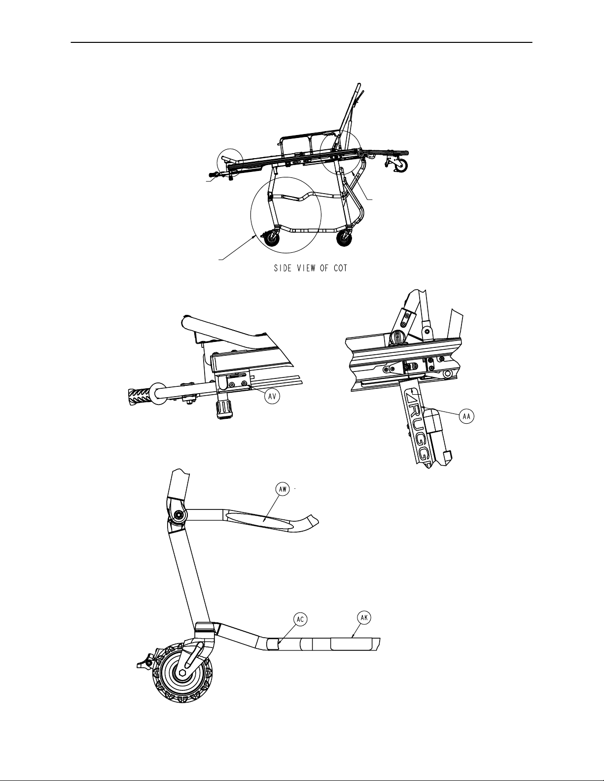
Detail A
Detail C
Cot Assembly
Detail B
DETAIL A
DETAIL B
DETAIL C
49
Page 52

Cot Assembly
50
Page 53

Cot Assembly
Item Part No. Part Name Qty. Item Part No. Part Name Qty.
A4−136 Pan Hd. Machine Screw 6 AG 6080−40−44 Link Release Spacer 1
B4−197 H. Soc. But. Hd. Cap Scr. 4 AH 6080−90−9 Warning Label 1
C4−198 H. Soc. But. Hd. Cap Scr. 2 AJ 4−161 H. Soc. But. Hd. Cap Screw 2
D4−135 H. Soc. But. Hd. Cap Scr. 1 AK 6080−90−108 “Lift Here” Label 2
F 6082−31−31 Clevis Pin 1 AL (page 53−58) Base Assembly 1
G11−16 Flat Washer 6 AM 6092−6−19 Auxiliary Lock Lever 1
H14−7 Nylon Washer 1 AN (page 71−75) Litter Assembly 1
J14−21 Flat Washer 2 AP 6092−30−43 Bumper 2
K8−30 Shoulder Bolt 1 AQ 6092−31−37 Head End Cover 1
L16−28 Fiberlock Nut 7 AR 6092−34−46 Midsection Skin 1
M28−181 Retaining Ring 1 AS (page 76) Breakaway Head Ass’y 1
N25−79 Dome Hd. Rivet 11 AT 16−2 Nylock Nut 1
P 6082−5−92 Modified Bushing 1 AV 6092−90−1 Aux. Lock Warning Label 1
Q81−298 Split Bearing 1 AW 6092−190−2EZ−PRO R4 Label 1
R 830−10−35 Crutch Tip 2 AX 6082−90
S 6091−5−70 Spacer Bushing 2 AY 11−448 Plain Washer 1
T 1010−31−77 Gas Cylinder 1 AZ 6092−40−55 Foot End Support 2
V 6092−31−46 Lit./Base I’face Piv. Spcr. 2 BB 6092−40−20 Aux. Lock Release Link 1
X 6060−37−26 Pivot Spacer Plate 2 BC 6092−40−23 Foot Release Upper Link 1
Y 6060−37−35 Outer Rail End Cap 2 BD 6092−40−25 Foot Release Lower Link 1
Z 6060−90−2 Serial Number Tag 1 BE 4−334 H. Soc. But. Hd. Cap Scr. 2
AA 6082−90−42 8” STRYKER Label 2 BF 4−518 H. Soc. But. Hd. Cap Scr. 3
AB 6060−90−4 Small “Rugged” Label 1 BG 6090−5−46 Tie Rod 3
AC 6060−90−114 “Keep Hands Clear” Label 2 BJ 11−45 Nylon Washer 1
AD 6070−90−107 “Lift to Release” Label 1 BK 6082−37−25 Strength Bracket 2
AF (page 52) Release Handle Assembly 1 BL 6092−190−40 EZ−Pro Tube Label 1
BM 6092−190−112 Specification Label 1
BP 25−132 Large Flange Rivet 4
BQ 6082−
−46 650lb Weight Cap. Label 2
1−85 2” Adhesive Loop Pile 2
51
Page 54

6092−40−40 Release Handle Assembly
Item Part No. Part Name Qty.
A 6080−40−41 Release Handle Link 1
B25−125 Semi−Tubular Rivet 2
C 6092−40−50 Side Release Handle 1
52
Page 55

Detail 1
Base Assembly
Assembly part number 6092−1−11 (reference only)
Detail 2
Detail 3
53
Page 56

DETAIL 1
Base Assembly
DETAIL 2
DETAIL 3
54
Page 57

Base Assembly
55
Apply stick wax
Page 58

Base Assembly
56
DETAIL 4 DETAIL 5
Page 59

Base Assembly
DETAIL 6
When assembling item AT bushing and
item AN nylon washer, ensure the bushing
is inserted completely through the nylon
washer. Verify the assembly moves freely
after assembling item N socket head cap screw.
DETAIL 7
DETAIL 8
Dual Retaining Post Option
57
Page 60

Base Assembly
Item Part No. Part Name Qty. Item Part No. Part Name Qty.
A3−205 Hex Hd. Cap Screw 4 BD 6091−1−32 Inner Base Spacer 2
B4−18 Soc. Hd. Cap Screw 2 BF 6092−1−33 Center Weldment 1
C4−45 H. Soc. But. Hd. Cap Scr. 2 BG 6091−1−52 Front Leg, Right 1
D4−136 Torx Pan Hd. Mach. Scr. 25 BH 6091−1−53 Front Leg, Left 1
E4−149 H. Soc. But. Hd. Cap Scr. 1 BJ 6091−1−57 Back Leg, Lower, Right 2
F4−161 But. Hd. Cap Screw 2 BK 6091−1−59 Back Leg, Lower, Left 1
G11−534 Washer 7 BL 6091−1−70 Base Bearing, Lower 8
H14−67 Washer 2 BM 6090−1−72 Center Bushing 4
J4−198 H. Soc. But. Hd. Cap Scr. 4 BN (page 61) Tie Rod Assembly, Right 1
K4−204 H. Soc. But. Hd. Cap Scr. 15 BP (page 61) Tie Rod Assembly, Left 1
L4−334 H. Soc. But. Hd. Cap Scr. 8 BQ (page 62) Bumper Tube Assembly, Lt. 1
M4−97 H. Soc. But. Hd. Cap Scr. 3 BR 6091−1−88 Bumper Plug 2
N4−325 H. Soc. But. Hd. Cap Scr. 8 BS 6090−1−89 Bumper Cap 2
P4−234 H. Soc. But. Hd. Cap Scr. 4 BT (page 62) Bumper Tube Assembly, Rt. 1
Q4−307 H. Soc. But. Hd. Cap Scr. 1 BU 6090−5−28 C−Channel End Cap 4
R4−319 H. Soc. Flat Hd. Screw 4 BV 6091−5−29 C−Channel, Left 1
S11
T11−16 Flat Washer 2 BX 6091−105−93 Latch Weldment, Foot, Right 1
U11−418 Flat Washer 4 BY 6091−105−91 Latch Lever, Foot, Left 1
V11−423 Spacer 2 BZ 6091−5−34 Lever Support, Foot End 1
X11−427 Flat Washer 4 CA (page 63) Latch Bar Assembly 1
Y16−3 Fiberlock Hex Nut 3 CB 6091−5−38 Latch Bar Weldment, Right 1
Z16−35 Fiberlock Hex Nut 2 CC 8−68 Soc. Hd. Shoulder Bolt 1
AA 16−28 Fiberlock Hex Nut 7 CD 6090−5−41 Spring Pulley 1
AB 16−60 Centerlock Nut 4 CF 6090−5−42 Spring Plunger 2
AC 16−78 Centerlock Hex Nut 8 CG 6090−5−43 Center Ret. Spring Housing 1
AD 25−133 Dome Head Rivet 6 CH 6090−5−44 Right Return Spring Housing 1
AE 28−178 Retaining Ring 2 CJ 4−455 But. Hd. Cap Screw 8
AF 16−2 Fiberlock Nut 1 CK 6090−5−47 Foot End Cross Tube 1
AG 34−273 Harness Wrap 1 CL 6092−5−32 Latch Lever, Head, Right 1
AH 34−274 Cable Clamp 2 CM 6092−5−50 Pivot Tube Boss, Head End 2
AJ 38−423 Extension Spring 1 CN 6090−5−51 Head End Cross Tube 1
AK 38−424 Extension Spring 1 CP (page 64) Lock Tube Assembly 1
AL 38−458 Extension Spring 1 CQ (page 65) Track Roller Assembly 4
AM 38−427 Extension Spring 1 CR (page 66) Cot Retaining Post Ass’y 1
AN 11−45 Washer 1 CS 6090−6−15 Aux. Lock Top Spacer 1
AP 38−530 Extension Spring 2 CT 6090−6−21 Aux. Lock Bottom Spacer 1
AQ 56−16 Bumper 2 CU 6091−6−23 Aux. Lock Slide Link Wldmt. 1
AR 81−244 Flange Bearing 8 CV 6091−6−24 Aux. Lock Supt. Brkt. Wldmt. 1
AS 81−291 Flange Bearing 12 CW (page 67) Aux. Lock Housing Ass’y 1
AT 6082−5−92 Modified Bushing 8 CY 6091−5−62 Stepped Insert 6
AU 81−294 Flange Bearing 1 CZ 6092−31−38 Fowler Bumper Supt. Brkt. 2
AV (page 60) Wheel Assembly 4 DD 14−30 Flat Washer 1
AW 6082−2−12 Caster Horn * DF 6092−5−65 Latch Lever, Head End, Left 1
AX 6060−32−42 Fow./Gatch Adapter Pivot 4 DG 11−454 Washer 1
AY 6090−1−9 Caster Nut 4 DH 6091−5−80 Trolley Support, Left 1
AZ 6090−1−15 Outer Base Tube 2 DJ 6091−5−82 Trolley Support, Right 1
BA 6091
BB 6090−1−27 Spindle Tube 4 DL 16−102 Nylock Hex Nut 8
BC 6090−1−28 Base Connecting Rod 2
−2 Flat Washer 4 BW 6091−5−30 C−Channel, Right 1
−1−63 Back Leg, Lower, Right 1 DK (page 68) Fowler Bracket 1
* If the cot is not equipped with the wheel lock option, item AW, Caster Horn, is a quantity of 4. If the cot is equipped with
the wheel lock option, item AW, Caster Horn, is a quantity of 2 or 3.
6091−190 Dual Retaining Post Option 6091−200 Right Retaining Post Option
Item Part No. Part Name Qty. Item Part No. Part Name Qty.
EA (page 66) Retaining Post Ass’y 1 EA 6090−5−40 Litter/Base Connector 1
EB 4−440 H. Soc. But. Hd. Cap Scr. 2 EB 4−198 H. Soc. But. Hd. Cap Scr. 2
58
Page 61

6092−257−10 Optional Lift Bar Assembly
Item Part No. Part Name Qty.
FA 4−235 Hex Soc. But. Hd. Cap Screw 2
FB 37−238 Hole Plug 2
FC 6092−157−11 Lift Tube 1
FD 6092−157−14 Bracket 2
59
Page 62

6060−2−10 Wheel Assembly
Item Part No. Part Name Qty.
A 6060−2−45 Molded Wheel 1
B 6060−2−46 Bearing Spacer 1
C81−226 Bearing 2
D 715−1−255 Wheel Bushing 2
60
Page 63

Tie Rod Assembly, Right & Left
6091−1−81 Left Tie Rod 6091−1−80 Right Tie Rod
Item Part No. Part Name Qty. Item Part No. Part Name Qty.
A 6091−1−83 Tie Rod Wear Guard, Lt. 1 A 6091−1−82 Tie Rod Wear Guard, Rt. 1
B 6091−1−94 Tie Rod Tube, Lt. 1 B 6091−1−93 Tie Rod Tube, Rt. 1
C25−79 Dome Head Rivet 3 C 25−79 Dome Head Rivet 3
61
Page 64

6090−205−000 Bumper Tube Assembly
6091−1−85 Left Bumper Tube 6091−1−90 Right Bumper Tube
Item Part No. Part Name Qty. Item Part No. Part Name Qty.
A 6091−1−86 Bumper Wear Guard, Lt. 1 A 6091−1−91 Bumper Wear Guard, Rt. 1
B 6091−1−95 Bumper Tube, Lt. 1 B 6091−1−96 Bumper Tube, Rt. 1
C25−79 Dome Head Rivet 5 C 25−79 Dome Head Rivet 5
62
Page 65

6091−700−115 Latch Bar Assembly
Item Part No. Part Name Qty.
A25−153 Semi−Tubular Rivet 2
B 6092−105−20 Latch Bar Spring Clip 1
C 6092−105−35 Latch Bar Weldment 1
63
Page 66

6091−005−565 Base Lock Tube Assembly
Item Part No. Part Name Qty.
A8−27 Shoulder Bolt 2
B28−177 Retaining Ring 2
C38−450 Compression Spring 2
D 6091−205−58 Lock Pin 2
E 6090−205−59 Lock Bar Roller 2
F 6091−5−63 Lock Bar Roller Guide 2
G (page 65) Lock Tube Bearing Ass’y 1
64
Page 67

6090−5−64 Base Lock Tube Bearing Assembly
Item Part No. Part Name Qty.
A 6090−5−68 Lock Bar Weldment 1
B81−4 Bronze Bushing 4
6090−5−70 Track Roller Assembly
Item Part No. Part Name Qty.
A 6090−5−75 Track Roller 1
B81−251 Track Roller Bushing 1
65
Page 68

Cot Retaining Post Assembly
6091−204−45 Cot Retaining Post 6091−4−46 Patient Left Cot Retaining Post
Item Part No. Part Name Qty. Item Part No. Part Name Qty.
A 6091−204−46 Retaining Post Head 1 A 6091−204−48 Retaining Post Head, Left 1
B 6091−204−47 Post Tube 1 B 6091−204−47 Post Tube 1
C 6060−4−43 Retaining Post Cap 1 C 6060−4−43 Retaining Post Cap 1
D4−163 H. Soc. But. Hd. Cap Scr. 1 D 4−163 Button Hd. Cap Screw 1
E 6091−90−3 Label 1
66
Page 69

6092−6−25 Auxiliary Lock Housing Assembly
Item Part No. Part Name Qty.
A4−161 Hex Soc. But. Hd. Cap Screw 1
B14−7 Nylon Washer 1
C16−28 Fiberlock Hex Nut 1
D38−432 Extension Spring 1
E 3001−300−99 Modified Bushing 1
F 6092−6−26 Auxiliary Lock Housing 1
G 6090−6−27 Auxiliary Lock Slide 1
H 6091−6−28 Auxiliary Lock Lever Arm 1
J3−364 Hex Washer Hd. Screw 1
67
Page 70

6092−32−10 Fowler Bracket Assembly
Item Part No. Part Name Qty.
A25−122 Dome Head Rivet 12
B 6092−32−11 Fowler Support Bracket 1
C 6092−32−12 Fowler Bracket Filler Panel 1
D 6092−32−13 Fowler Supt. Brkt. Mount, Rt. 1
E 6092−32−14 Fowler Supt. Brkt. Mount, Lt. 1
68
Page 71

Wheel Lock Options
6082−501−10 One Wheel Lock Option
Item Part No. Part Name Qty.
A 6082−2−12 Caster Horn 1
B (page 70) Wheel Lock Ass’y 1
6082−502−10 Two Wheel Locks Option
Item Part No. Part Name Qty.
B (page 70) Wheel Lock Ass’y 2
69
Page 72

6082−200−10 Adjustable Wheel Lock Assembly
Item Part No. Part Name Qty.
A 6082−100−12 Caster Horn 1
B 6080−100−32 Spring 1
C11−456 Washer 1
D25−153 Semi−Tubular Rivet 2
E 6080−90−101 Warning Label 2
F 6080−200−30 Adjustable Pedal 1
G 6080−200−41 Octagonal Sleeve 1
H4−98 Hex Soc. But. Hd. Cap Screw 1
I16−118 Centerlock Nut 1
70
Page 73

Litter Assembly
Assembly part number 6092−30−11 (reference only)
71
Page 74

Litter Assembly
DETAIL 1
DETAIL 2
72
Page 75

Litter Assembly
DETAIL 3
DETAIL 4
DETAIL 5
73
Page 76

Litter Assembly
DETAIL 6
74
Page 77

Litter Assembly
Item Part No. Part Name Qty. Item Part No. Part Name Qty.
B4−135 Hex Soc. But. Hd. Cap Scr. 2 AK 946−35−25 Liner 2
C4−515 Pan Hd. Machine Scr. 6 AL 6082−25−33 Pivot Mount Spacer 8
D4−161 Hex Soc. But. Hd. Cap Scr. 4 AM 6082−25−55 Pivot Mount 6
E4−468 Hex Soc. But. Hd. Cap Scr. 12
F4−197 Hex Soc. But. Hd. Cap Scr. 2 AN (page 76) Siderail Assembly 2
G4−198 Hex Soc. But. Hd. Cap Scr. 12 AP 6082−30−31 Crossbrace Supt. Mnt. 4
H4−204 Hex Soc. But. Hd. Cap Scr. 8 AQ 6060−32−38 Gas Spring Yoke 1
K4−234 Hex Soc. But. Hd. Cap Scr. 1 AR 6060−32−40 Fowler Lift Pivot 1
L8−27 Hex Soc. Hd. Shoulder Bolt 1 AS 6100−3−125 Fow./Gatch Adptr. Pivot 4
M14−67 Flat Washer 2 AT 6082−32−52 Rel. Handle Wldmnt. 1
N14−55 Flat Washer 2 AU 6070−38−33 Calf Stand Retainer 1
P15−50 Hex Nut 1 AV 6082−30−42 Litter Crossbrace 2
R16−28 Fiberlock Hex Nut 12 AW 6082−32−45 Fowler Skin 1
S16−78 Centerlock Hex Nut 1 AX 6082−32−50 Fowler Weldment 1
T16−102 Nylock Nut 8 AY 6082−38−31 Calf Stand Support, Lt. 1
U18−
V21−119 Hex Soc. Set Screw 1 BA 6082−38−35 Litter Cross Brace 1
W21−138 Hex Soc. Set Screw 1 BB 6082−38−45 Foot Section Skin 1
X25−79 Dome Hd. Rivet 36 BC 6082−38−46 Foot Section Tube 1
Y25−128 Flange Rivet 1 BD 6092−40−12 Outer Rail End Cap, Ft. 2
Z25−132 Flange Rivet 4 BE 34−74 Hole Plug 2
AA 25−133 Dome Hd. Rivet 6 BF 6092−30−46 Outer Rail, Right 1
AB 25−131 Semi−Tubular Rivet 2 BG 6092−30−47 Outer Rail, Left 1
AC 28−76 External Retaining Ring 2 BH 6092−33−32 Trend Support, Left 1
AD 56−16 Bumper 2 BJ 6092−33−33 Trend Support, Right 1
AE 81−255 Split Bearing 2 BK 6090−39−43 Lift Bar Plug 2
AF 378−24−29 Shoulder Bolt 1 BL (page 77) Lift Tube 1
AG 721−26−66 Pivot Screw 6 BM 6092−40−48 Lift Tube Support 1
AJ 938−1−177 Knob 1 BN 6092−40−49 Lift Tube Support, Rt. 1
38 Umbrella Nut 2 AZ 6082−38−32 Calf Stand Support, Rt. 1
75
Page 78

6092−26−10 Folddown Siderail Assembly
Item Part No. Part Name Qty.
A 6060−25−24 Top Rail 1
B 6060−25−29 Lock Release 1
C 6060−25−35 Pivot Bushing 4
D 6060−25−40 Spindle Pivot Stop 1
E 6060−25−41 Spindle Pivot 4
F 6060−25−43 Siderail Spindle 3
G 6060−25−47 Spindle Lock Post 1
H 6061−125−30 Lock Bar 1
J25−131 Semi−Tubular Rivet 4
K38−344 Compression Spring 1
76
Page 79

6092−40−51 Litter Lift Tube Assembly
Item Part No. Part Name Qty.
A 6080−40−11 Grip 2
B 6092−40−52 Lift Tube 1
77
Page 80

Breakaway Head Section Assembly
Assembly part number 6080−37−56 (Reference only)
B
Spring (both sides) should
be installed with lower hook
opening facing foot end.
A
B
78
Page 81

Breakaway Head Section Assembly
Item Part No. Part Name Qty.
A4−54 Button Head Cap Screw 2
B4−163 Button Head Cap Screw 4
C4−197 Button Head Cap Screw 4
D4−204 Button Head Cap Screw 6
E4−209 Button Head Cap Screw 2
F4−231 Button Head Cap Screw 4
G4−612 Button Head Cap Screw 2
H16−20 Centerlock Hex Jam Nut 2
J16−28 Fiberlock Hex Nut 4
K16−102 Nylock Hex Nut 12
L26−269 Clevis Pin 2
M28−138 External Retaining Ring 2
N38−410 Extension Spring 2
P 721−31−65 Hole Plug 2
R 6060−36−20 Wheel Assembly, 5 inch 2
S 6060−36−24 Pivot Stop Pin, Breakaway Hd. 2
T 6060−37−26 Spacer Plate, Pivot 2
U 6060−37−33 Horn Stop Block, Breakaway Hd.2
V 6060−37−36 Spacer, Trigger Lock, Pivot 2
W 6060−37−37 Pivot Cover, Right 1
X 6060−37−38 Pivot Cover, Left 1
Y 6080−36−44 Bumper 1
Z 6080−36−45 Outer Rail, Breakaway Head 1
AA 6080−37−27 Outer Caster Horn, Left 1
AB 6080−37−28 Outer Caster Horn, Right 1
AC 6080−37−29 Inner Caster Horn, Left 1
AD 6080−37−30 Inner Caster Horn, Right 1
AE 6080−37−34 Pivot Tube, Safety Hook 1
AF 6080−37−49 Safety Hook, Rel Hndl, Spacer 2
AG 6080−37−25 Bracket, Litter/Base Adapter 2
AH 6082−37−42 Pivot, Form, Right 2
AJ 6082−37−43 Pivot, Form, Left 2
AK 6082−37−57 Grooved Clevis Pin Assembly 2
AL 6090−37−39 Trigger Lock 2
AM 6500−1−321 Safety Bar Torsion Spring 2
AN 6500−1−323 Pivot, Safety Hook, PR 1
AP 6500−1−324 Pivot, Safety Hook, PL 1
79
Page 82

Breakaway Head Section Assembly
Note: Need to order Lift option (6091−156−016)
to complete functional head section.
Breakaway Head Assembly − Standard Components − 6080−37−10 (reference only)
Item Part No. Part Name Qty.
BA 14−67 Nylon Flat Washer 2
BB 25−79 Dome Head Rivet 2
BC 28−138 Retaining Ring 2
BD 6080−36−25 Pivot Pin 2
BE 6080−36−47 Crossbar, Release, Bent 1
BF 6080−37−55 Breakaway Head Section 1
80
Page 83

Breakaway Head Section Assembly
Breakaway Head Assembly − Standard Height Option − 6082−37 (reference only)
Item Part No. Part Name Qty.
CA 6082−37−40 Center Pivot, Head Section 2
Breakaway Head Assembly − Extended Height Option − 6082−38 (reference only)
Item Part No. Part Name Qty.
DA 6082−343−85 Center Pivot, Ext, Head Section 2
81
Page 84
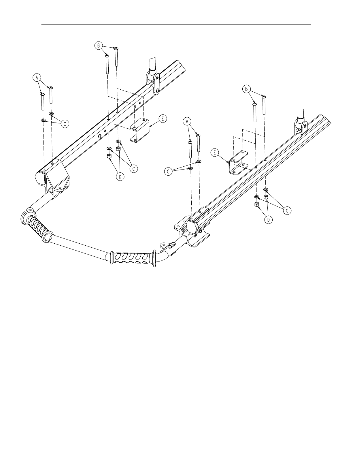
6092−213−10 No IV Pole Option
Item Part No. Part Name Qty.
A4−97 Hex Soc. But. Hd. Cap Screw 4
B4−163 Hex Soc. But. Hd. Cap Screw 4
C11−65 Flat Washer 8
D16−28 Nylock Nut 4
E 6092−30−80 Siderail Bracket 2
82
Page 85
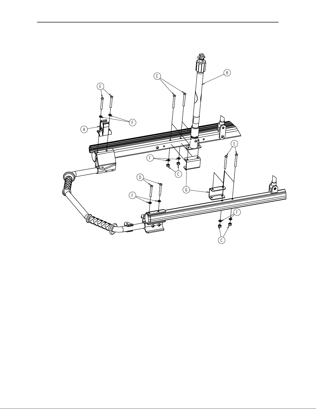
6092−210−10 Optional 2−Stage IV, Patient Right
6092−215−10 Optional 3−Stage IV, Patient Right
PATIENT RIGHT
FOOT END
6092−210−10 6092−215−10
Item Part No. Part Name Qty. Item Part No. Part Name Qty.
A 6080−110 −35 IV Clip 1 A 6080−110 −35 IV Clip 1
B (page 84) 2−Stage IV Pole, Right 1 B (page 82) 3−Stage IV Pole, Right 1
C16−28 Nylock Nut 4 C 16−28 Nylock Nut 4
D4−97 Hex Soc. But. Hd. Cap Scr. 2 D 4−97 Hex Soc. But. Hd. Cap Scr. 2
E4−163 Hex Soc. But. Hd. Cap Scr. 6 E 4−163 Hex Soc. But. Hd. Cap Scr. 6
F11−65 Flat Washer 8 F 11−65 Flat Washer 8
G 6092−30−80 Siderail Bracket 1 G 6092−30−80 Siderail Bracket 1
83
Page 86

6090−210−20 2−Stage IV Assembly, Patient Right
Item Part No. Part Name Qty.
A 6070−90−105 Caution Label 1
B (page 89) 2−Stage IV Pole Assembly 1
C 6070−11 0 −37 IV Pivot Pin 1
D25−79 Dome Head Rivet 1
F 6090−90−31 Specification Label 1
G 6100−11 5 −51 Socket Weldment 1
84
Page 87

6090−215−20 3−Stage IV Assembly, Patient Right
Item Part No. Part Name Qty.
A 6070−90−105 Caution Label 1
C 6070−11 0 −37 IV Pivot Pin 1
D25−79 Dome Head Rivet 1
E (page 90) 3−Stage I.V. Pole Assembly 1
F 6090−90−33 Specification Label 1
G 6100−11 5 −51 Socket Weldment 1
85
Page 88

6092−211−10 Optional 2−Stage IV, Patient Left
6092−216−10 Optional 3−Stage IV, Patient Left
PATIENT LEFT
FOOT END
6092−211−10 6092−216−10
Item Part No. Part Name Qty. Item Part No. Part Name Qty.
A 6080−110 −35 IV Clip 1 A 6080−110 −35 IV Clip 1
B (page 87) 2−Stage IV Pole, Left 1 B (page 88) 3−Stage IV Pole, Left 1
C16−28 Nylock Nut 4 C 16−28 Nylock Nut 4
D4−97 H. Soc. But. Hd. Cap Scr. 2 D 4−97 H. Soc. But. Hd. Cap Scr. 2
E4−163 H. Soc. But. Hd. Cap Scr. 6 E 4−163 H. Soc. But. Hd. Cap Scr. 6
F11−65 Flat Washer 8 F 11−65 Flat Washer 8
G 6092−30−80 Siderail Bracket 1 G 6092−30−80 Siderail Bracket 1
86
Page 89

6090−211−20 2−Stage IV Assembly, Patient Left
Item Part No. Part Name Qty.
A 6070−90−105 Caution Label 1
B (page 89) 2−Stage IV Pole Assembly 1
C 6070−1100−37 IV Pivot Pin 1
D25−79 Dome Head Rivet 1
F 6090−90−32 Specification Label 1
G 6100−11 5 −51 Socket Weldment 1
87
Page 90

6090−216−20 3−Stage IV Assembly, Patient Left
Item Part No. Part Name Qty.
A 6070−90−105 Caution Label 1
B 6070−11 0 −37 IV Pivot Pin 1
C25−79 Dome Head Rivet 1
E (page 90) 3−Stage IV Pole Assembly 1
F 6090−90−34 Specification Label 1
G 6100−11 5 −51 Socket Weldment 1
88
Page 91

6070−210−70 2−Stage IV Pole Assembly
Item Part No. Part Name Qty.
A 1210−11 0 −46 Back−Up Ring 1
B 1210−11 0 −47 Lock Ring 1
C 1210−11 0 −49 Molded Actuator 1
D 6070−210−51 Base Tube 1
E 6070−11 0 −42 2nd Stage Tube 1
F 6070−11 0 −51 2nd Stage Slide Plug 1
G 6070−11 0 −50 Hook Weldment 1
H26−6 Roll Pin 2
J 6070−11 0 −12 I.V. Pole Pivot 1
89
Page 92

6070−215−70 3−Stage IV Pole Assembly
Item Part No. Part Name Qty.
A 1210−11 0 −46 Back−Up Ring 1
B 1210−11 0 −47 Lock Ring 1
C 1210−11 0 −49 Molded Actuator 1
D 6070−210−51 Base Tube 1
E 6070−11 0 −51 2nd Stage Slide Plug 1
F 6070−11 0 −50 Hook Weldment 1
G (page 91) 3rd Stage Assembly 1
H 6070−11 5 −42 2nd Stage Tube 1
I 6070−11 5 −45 Bearing Plug 1
J26−5 Spring Pin 1
K26−6 Spring Pin 1
L 6070−11 0 −12 I.V. Pole Pivot 1
90
Page 93

6070−115−30 3−Stage I.V. Pole 3rd Stage Assembly
Item Part No. Part Name Qty.
A 6070−11 5 −141 Spring Clip 1
B 6070−11 5 −143 3rd Stage Tube 1
C 6070−11 5 −44 3rd Stage Slide Plug 1
D26−4 Roll Pin 1
E45−139 O−Ring 1
91
Page 94

6092−212−10 Optional Dual 2−Stage IV Pole Assembly
FOOT END
Item Part No. Part Name Qty.
A4−163 Hex Soc. But. Hd. Cap Screw 8
B11−65 Flat Washer 8
C16−28 Nylock Nut 4
D 6080−11 0 −35 IV Clip 2
E (page 84) 2−Stage IV Pole, Right 1
F (page 87) 2−Stage IV Pole, Left 1
G 6092−30−80 Siderail Bracket 2
92
Page 95

6092−217−10 Dual 3−Stage IV Pole Assembly
FOOT END
Item Part No. Part Name Qty.
A4−163 Hex Soc. But. Hd. Cap Screw 8
B11−65 Flat Washer 8
C16−28 Nylock Nut 4
D 6080−11 0 −35 IV Clip 2
E (page 82) 3−Stage IV Pole, Right 1
F (page 88) 3−Stage IV Pole, Left 1
G 6092−30−80 Siderail Bracket 2
93
Page 96

6092−155−20 Optional Pull Handle Assembly
Item Part No. Part Name Qty.
A4−136 But. Hd. Cap Screw 4
B4−265 Hex Soc. But. Hd. Cap Screw 1
C11−16 Flat Washer 4
D16−14 Nylock Hex Nut 1
E25−79 Dome Head Rivet 4
F 958−1−224 I.V. Clip 1
G 6092−155−50 Pull Handle Holder Bracket 1
H 6090−155−51 Pull Handle Retainer Clamp 2
J 6090−155−53 Threaded Spacer 2
K 6092−155−52 Pull Handle 1
L 6092−155−55 Pull Handle Spacer 1
94
Page 97
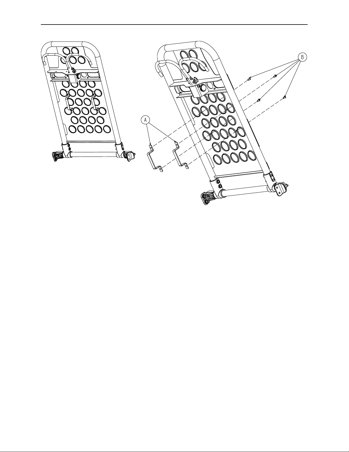
6091−300−10 Pedi−Matet Restraint Bracket Option
Item Part No. Part Name Qty.
A 6080−32−60 Restraint Bracket 2
B25−79 Rivet 4
95
Page 98

6080−140 Optional Hanging Oxygen Bottle Holder Ass’y
Item Part No. Part Name Qty.
A 6080−140−11 Bottle Holder Hanger 2
B 6080−140−12 Oxygen Bottler Holder 1
96
Page 99

6092−140 Optional Foot End O2 Bottle Holder
Item Part No. Part Name Qty.
A 6060−140−13 Strap Assembly 2
B (page 98) Bottle Holder Tray 1
C25−79 Dome Hd. Rivet 12
D 6092−140−17 Bottle Holder 1
E 6092−90−14 Specification Label 1
97
Page 100

6060−140−20 Foot End O2 Bottle Holder Tray
Item Part No. Part Name Qty.
A11−436 Flat Washer 4
B25−133 Rivet 7
C37−55 Cap 4
D37−56 Washer 4
E 946−1−155 Bumper 7
F 6060−140−15 Bottle Holder Tray 1
98
 Loading...