


Stryker Renaissance 1066 Maintenance Manual
IMPORTANT
File in your
maintenance
records
Renaissance Series
1066 Head/Neck Surgery Bed
MAINTENANCE MANUAL
For Parts or Technical Assistance
1–800–327–0770

Table of Contents
INTRODUCTION 3. . . . . . . . . . . . . . . . . . . . . . . . . . . . . . . . . . . . . . . . . . . . . . . . . . . . . . . . . . . . . . . . . . . . . . . . . . .
SPECIFICATIONS 3. . . . . . . . . . . . . . . . . . . . . . . . . . . . . . . . . . . . . . . . . . . . . . . . . . . . . . . . . . . . . . . . . . . . . . . . .
WARNING / CAUTION / NOTE DEFINITION 3. . . . . . . . . . . . . . . . . . . . . . . . . . . . . . . . . . . . . . . . . . . . . . . . . .
PREVENTATIVE MAINTENANCE 4. . . . . . . . . . . . . . . . . . . . . . . . . . . . . . . . . . . . . . . . . . . . . . . . . . . . . . . . . . . .
SIDERAIL LATCH ADJUSTMENT 5. . . . . . . . . . . . . . . . . . . . . . . . . . . . . . . . . . . . . . . . . . . . . . . . . . . . . . . . . . . .
TRANSFER BOARD COUNTERBALANCE ADJUSTMENT 5. . . . . . . . . . . . . . . . . . . . . . . . . . . . . . . . . . . . . .
PEDAL LINKAGE ADJUSTMENT – DUAL SIDE CONTROL BASE 6. . . . . . . . . . . . . . . . . . . . . . . . . . . . . . .
PEDAL LINKAGE ADJUSTMENT – DUAL END CONTROL BASE 7. . . . . . . . . . . . . . . . . . . . . . . . . . . . . . . .
CASTER ASSEMBLY REPLACEMENT 8. . . . . . . . . . . . . . . . . . . . . . . . . . . . . . . . . . . . . . . . . . . . . . . . . . . . . . .
HYDRAULIC SYSTEM TROUBLESHOOTING 9. . . . . . . . . . . . . . . . . . . . . . . . . . . . . . . . . . . . . . . . . . . . . . . . .
CHECKING HYDRAULIC FLUID LEVEL 10. . . . . . . . . . . . . . . . . . . . . . . . . . . . . . . . . . . . . . . . . . . . . . . . . . . . .
REMOVING EXCESS AIR FROM THE HYDRAULIC SYSTEM 10. . . . . . . . . . . . . . . . . . . . . . . . . . . . . . . . . .
JACK DESCENT RATE ADJUSTMENT 11. . . . . . . . . . . . . . . . . . . . . . . . . . . . . . . . . . . . . . . . . . . . . . . . . . . . . .
HYDRAULIC CHECK VALVE REPLACEMENT
Replacement Of Valve #1 12. . . . . . . . . . . . . . . . . . . . . . . . . . . . . . . . . . . . . . . . . . . . . . . . . . . . . . . . . . . . . . . .
Replacement Of Valve #2 13. . . . . . . . . . . . . . . . . . . . . . . . . . . . . . . . . . . . . . . . . . . . . . . . . . . . . . . . . . . . . . . .
Replacement Of Valve #3 13. . . . . . . . . . . . . . . . . . . . . . . . . . . . . . . . . . . . . . . . . . . . . . . . . . . . . . . . . . . . . . . .
BRAKE ADJUSTMENT 14. . . . . . . . . . . . . . . . . . . . . . . . . . . . . . . . . . . . . . . . . . . . . . . . . . . . . . . . . . . . . . . . . . . .
BASE LUBRICATION POINTS 14. . . . . . . . . . . . . . . . . . . . . . . . . . . . . . . . . . . . . . . . . . . . . . . . . . . . . . . . . . . . . .
ASSEMBLY DRAWINGS AND PARTS LISTS
Side Control Base Assembly (with Wheels) 16, 17. . . . . . . . . . . . . . . . . . . . . . . . . . . . . . . . . . . . . . . . . . .
Brake Adjuster Assembly 18. . . . . . . . . . . . . . . . . . . . . . . . . . . . . . . . . . . . . . . . . . . . . . . . . . . . . . . . . . . . . . . . .
Brake Cam Assembly 19. . . . . . . . . . . . . . . . . . . . . . . . . . . . . . . . . . . . . . . . . . . . . . . . . . . . . . . . . . . . . . . . . . . .
Brake Pedal Assembly, Side Control Base 20. . . . . . . . . . . . . . . . . . . . . . . . . . . . . . . . . . . . . . . . . . . . . . . . . .
Steering Caster Assembly 21. . . . . . . . . . . . . . . . . . . . . . . . . . . . . . . . . . . . . . . . . . . . . . . . . . . . . . . . . . . . . . . .
Caster and Cover Assembly 22. . . . . . . . . . . . . . . . . . . . . . . . . . . . . . . . . . . . . . . . . . . . . . . . . . . . . . . . . . . . . .
Fifth Wheel Assembly 23. . . . . . . . . . . . . . . . . . . . . . . . . . . . . . . . . . . . . . . . . . . . . . . . . . . . . . . . . . . . . . . . . . . .
End Control Base Assembly (with Wheels) 24, 25. . . . . . . . . . . . . . . . . . . . . . . . . . . . . . . . . . . . . . . . . . . .
End Control Brake Pedal Assembly, Foot 26. . . . . . . . . . . . . . . . . . . . . . . . . . . . . . . . . . . . . . . . . . . . . . . . . . .
End Control Brake Pedal Assembly, Head 27. . . . . . . . . . . . . . . . . . . . . . . . . . . . . . . . . . . . . . . . . . . . . . . . . .
Side Control Base Assembly (with Jacks) 28, 29. . . . . . . . . . . . . . . . . . . . . . . . . . . . . . . . . . . . . . . . . . . . .
Pedal Base Assembly, Pump 30. . . . . . . . . . . . . . . . . . . . . . . . . . . . . . . . . . . . . . . . . . . . . . . . . . . . . . . . . . . . .
Pedal Base Assembly, Head End, Left 31. . . . . . . . . . . . . . . . . . . . . . . . . . . . . . . . . . . . . . . . . . . . . . . . . . . . .
Pedal Base Assembly, Head End, Right 32. . . . . . . . . . . . . . . . . . . . . . . . . . . . . . . . . . . . . . . . . . . . . . . . . . . .
Side Control Hood Assembly 33. . . . . . . . . . . . . . . . . . . . . . . . . . . . . . . . . . . . . . . . . . . . . . . . . . . . . . . . . . . . .
End Control Base Assembly (with Jacks) 34, 35. . . . . . . . . . . . . . . . . . . . . . . . . . . . . . . . . . . . . . . . . . . . .
Pump Pedal Assembly, Head 36. . . . . . . . . . . . . . . . . . . . . . . . . . . . . . . . . . . . . . . . . . . . . . . . . . . . . . . . . . . . .
Pump Pedal Assembly, Foot 36. . . . . . . . . . . . . . . . . . . . . . . . . . . . . . . . . . . . . . . . . . . . . . . . . . . . . . . . . . . . . .
End Control Base Hood Assembly 37. . . . . . . . . . . . . . . . . . . . . . . . . . . . . . . . . . . . . . . . . . . . . . . . . . . . . . . . .
Jack Assembly 38. . . . . . . . . . . . . . . . . . . . . . . . . . . . . . . . . . . . . . . . . . . . . . . . . . . . . . . . . . . . . . . . . . . . . . . . . .
Jack Base Assembly 39. . . . . . . . . . . . . . . . . . . . . . . . . . . . . . . . . . . . . . . . . . . . . . . . . . . . . . . . . . . . . . . . . . . .
Base Labeling Assembly 40. . . . . . . . . . . . . . . . . . . . . . . . . . . . . . . . . . . . . . . . . . . . . . . . . . . . . . . . . . . . . . . . .
Litter Assembly 41–43. . . . . . . . . . . . . . . . . . . . . . . . . . . . . . . . . . . . . . . . . . . . . . . . . . . . . . . . . . . . . . . . . . . . .
Jack Support and Trend. Limiter Assembly 44. . . . . . . . . . . . . . . . . . . . . . . . . . . . . . . . . . . . . . . . . . . . . . . . .
Trend. Limiter Assembly 45. . . . . . . . . . . . . . . . . . . . . . . . . . . . . . . . . . . . . . . . . . . . . . . . . . . . . . . . . . . . . . . . .
Transfer System Assembly, Left 46. . . . . . . . . . . . . . . . . . . . . . . . . . . . . . . . . . . . . . . . . . . . . . . . . . . . . . . . . . .
Transfer System Assembly, Right 47. . . . . . . . . . . . . . . . . . . . . . . . . . . . . . . . . . . . . . . . . . . . . . . . . . . . . . . . .
Board Support Assembly 48. . . . . . . . . . . . . . . . . . . . . . . . . . . . . . . . . . . . . . . . . . . . . . . . . . . . . . . . . . . . . . . . .
Crank Fowler Assembly 49. . . . . . . . . . . . . . . . . . . . . . . . . . . . . . . . . . . . . . . . . . . . . . . . . . . . . . . . . . . . . . . . . .
Crank Fowler Subassembly 50, 51. . . . . . . . . . . . . . . . . . . . . . . . . . . . . . . . . . . . . . . . . . . . . . . . . . . . . . . . . . . .
Fowler Crankscrew Assembly 52. . . . . . . . . . . . . . . . . . . . . . . . . . . . . . . . . . . . . . . . . . . . . . . . . . . . . . . . . . . . .
Knee Gatch Assembly 53. . . . . . . . . . . . . . . . . . . . . . . . . . . . . . . . . . . . . . . . . . . . . . . . . . . . . . . . . . . . . . . . . . .
Knee Gatch Preassemblies 54. . . . . . . . . . . . . . . . . . . . . . . . . . . . . . . . . . . . . . . . . . . . . . . . . . . . . . . . . . . . . . .

Table of Contents
ASSEMBLY DRAWINGS AND PARTS LISTS (CONTINUED)
Knee Gatch Crankscrew Assembly 55. . . . . . . . . . . . . . . . . . . . . . . . . . . . . . . . . . . . . . . . . . . . . . . . . . . . . . . .
Footsection Assembly 56. . . . . . . . . . . . . . . . . . . . . . . . . . . . . . . . . . . . . . . . . . . . . . . . . . . . . . . . . . . . . . . . . . .
Handle Assembly 57. . . . . . . . . . . . . . . . . . . . . . . . . . . . . . . . . . . . . . . . . . . . . . . . . . . . . . . . . . . . . . . . . . . . . . .
Wrist Rest Assembly 58. . . . . . . . . . . . . . . . . . . . . . . . . . . . . . . . . . . . . . . . . . . . . . . . . . . . . . . . . . . . . . . . . . . .
Upright Assembly 59. . . . . . . . . . . . . . . . . . . . . . . . . . . . . . . . . . . . . . . . . . . . . . . . . . . . . . . . . . . . . . . . . . . . . . .
Knob Assembly 60. . . . . . . . . . . . . . . . . . . . . . . . . . . . . . . . . . . . . . . . . . . . . . . . . . . . . . . . . . . . . . . . . . . . . . . . .
Poat–Op Head Addition Assembly 61. . . . . . . . . . . . . . . . . . . . . . . . . . . . . . . . . . . . . . . . . . . . . . . . . . . . . . . . .
Inflatable Air System Head Pad 62. . . . . . . . . . . . . . . . . . . . . . . . . . . . . . . . . . . . . . . . . . . . . . . . . . . . . . . . . . .
Sheet Support Assembly 63. . . . . . . . . . . . . . . . . . . . . . . . . . . . . . . . . . . . . . . . . . . . . . . . . . . . . . . . . . . . . . . . .
Siderail Assembly 64. . . . . . . . . . . . . . . . . . . . . . . . . . . . . . . . . . . . . . . . . . . . . . . . . . . . . . . . . . . . . . . . . . . . . . .
Drainage Pan Assembly 65. . . . . . . . . . . . . . . . . . . . . . . . . . . . . . . . . . . . . . . . . . . . . . . . . . . . . . . . . . . . . . . . . .
Permanent I.V. Pole Assembly) 66. . . . . . . . . . . . . . . . . . . . . . . . . . . . . . . . . . . . . . . . . . . . . . . . . . . . . . . . . . .
Permanent I.V. to Frame Assembly 67. . . . . . . . . . . . . . . . . . . . . . . . . . . . . . . . . . . . . . . . . . . . . . . . . . . . . . . .
Replacement I.V. Pole 68. . . . . . . . . . . . . . . . . . . . . . . . . . . . . . . . . . . . . . . . . . . . . . . . . . . . . . . . . . . . . . . . . . .
Foot Board/Chartholder Assembly 69. . . . . . . . . . . . . . . . . . . . . . . . . . . . . . . . . . . . . . . . . . . . . . . . . . . . . . . . .
Oxygen Bottle Holder Assembly 69. . . . . . . . . . . . . . . . . . . . . . . . . . . . . . . . . . . . . . . . . . . . . . . . . . . . . . . . . . .
Defibrillator Tray Assembly 70. . . . . . . . . . . . . . . . . . . . . . . . . . . . . . . . . . . . . . . . . . . . . . . . . . . . . . . . . . . . . . .
Foot Extension/Defibrillator Tray Assembly 71. . . . . . . . . . . . . . . . . . . . . . . . . . . . . . . . . . . . . . . . . . . . . . . . .
Warranty
Obtaining Parts and Service 72. . . . . . . . . . . . . . . . . . . . . . . . . . . . . . . . . . . . . . . . . . . . . . . . . . . . . . . . . . . . . .
Supplemental Warranty Coverage 72. . . . . . . . . . . . . . . . . . . . . . . . . . . . . . . . . . . . . . . . . . . . . . . . . . . . . . . . .
Return Authorization 73. . . . . . . . . . . . . . . . . . . . . . . . . . . . . . . . . . . . . . . . . . . . . . . . . . . . . . . . . . . . . . . . . . . . .
Freight Damage Claims 73. . . . . . . . . . . . . . . . . . . . . . . . . . . . . . . . . . . . . . . . . . . . . . . . . . . . . . . . . . . . . . . . . .

Introduction
INTRODUCTION
This manual is designed to assist you with the operation and maintenance of the 1066 Head/Neck Surgery
Bed. Read it thoroughly before using the equipment or beginning any maintenance on it.
SPECIFICATIONS
Maximum Weight Capacity 500 pounds
Overall Bed Length/Width 88”, 31.5”
Minimum/Maximum Bed Height 22.5”/36”
Fowler Angle 0 to 90 degrees
Knee Gatch Angle 0 to 35 degrees
Trendelenburg/Reverse Trendelenburg –15 degrees t +17 degrees
WARNING / CAUTION / NOTE DEFINITION
The words WARNING, CAUTION and NOTE carry special meanings and should be carefully reviewed.
WARNING
The personal safety of the patient or user may be involved. Disregarding this information could result in injury
to the patient or user.
CAUTION
These instructions point out special procedures or precautions that must be followed to avoid damaging the
equipment.
NOTE
This provides special information to make maintenance easier or important instructions clearer.
3

Preventative Maintenance
CLEANING
1. Hand wash all surfaces of the bed with warm water and mild detergent. Dry thoroughly.
2. Clean Velcro AFTER EACH USE. Saturate Velcro with disinfectant and allow disinfectant to evaporate.
(Appropriate disinfectant for nylon Velcro should be determined by the hospital.)
BIANNUAL CHECKLIST
All fasteners and knobs secure (reference all assembly prints)
Siderails move and latch properly (page 5)
All casters lock with brake pedal engaged (page 14)
Steer function working properly
All casters secure and swivel properly
Body restraints working properly
I.V. pole intact and operating properly (page 66–68)
Oxygen bottle holder intact and operating properly (page 33, 37 or 69)
Fowler operates and latches properly
Knee Gatch operates properly (page 53)
Trendelenberg/Reverse Trendelenberg operating properly
No rips or cracks in mattress cover
Transfer boards intact and operating properly (page 5)
Arm board support levers intact and operating properly (page 48)
Ground chain intact
No leaks at hydraulic connections
Hydraulic jacks holding properly (page 9)
Hydraulic drop rate set properly (page 11)
Hydraulic oil level sufficient (page 10)
Lubricate where required, including the brake adjuster assembly and brake cam (page 14)
Serial No.______________
______________
______________
______________
______________
Completed By:_________________________________ Date:_____________
4

Service Information
SIDERAIL LATCH ADJUSTMENT
Required Tools:
1/8 Hex Allen Wrench
WARNING
The siderail latch adjustment is pre–set at the factory, and there should not normally be a need for readjustment. If adjustment must be done it is important to follow the procedure below. If it is no t don e pro per ly, injury
to the patient or user could occur.
Adjustment Procedure:
1. Using a 1/8 hex Allen wrench, adjust the hex Allen screw located on the latch assembly opposite the latch.
Turning the Allen screw clockwise will DECREASE the amount of ”play” in the latching mechanism. Turn-
ing counterclockwise will INCREASE the amount.
NOTE
The amount of ”play” in the siderail, when in full up engaged position, should be approximately 1/8 to 3/16
inches.
CAUTION
Too much ”play” when the siderail is in the full up engaged position will give the siderail the appearance of
being unstable and could also cause premature wearing of the latch system.
Too little ”play” will obstruct the latch and keep it from engaging completely in the full up position, which may
cause damage to the latch and/or injury to the patient or user.
TRANSFER BOARD COUNTERBALANCE ADJUSTMENT
Required Tools:
7/16 Open End Wrench
Adjustment Procedure:
1. Raise the transfer board to the full up position.
2. Unhook the extension spring at the eye bolt.
3. Using a 7/16 open end wrench, loosen the jam nut at the eye bolt.
4. Adjust the eye bolt to the desired position.
5. Tighten the jam nut.
6. Hook the extension spring to the eye bolt.
7. Allow the transfer board to lower on its own.
8. Repeat steps 1–7 until the desired counterbalance is achieved.
5
Service Information
PEDAL LINKAGE ADJUSTMENT – DUAL SIDE CONTROL BASE
Required Tools:
3/32 Hex Allen Wrench
7/16 Open End Wrench
1/2 Open End Wrench
(2) Wooden blocks (10 – 12 inches in length)
Adjustment Procedure:
1. Pump the litter up to full height.
2. Lift the base hood, separating the hood from the base frame. Using the wooden blocks, support the base
hood.
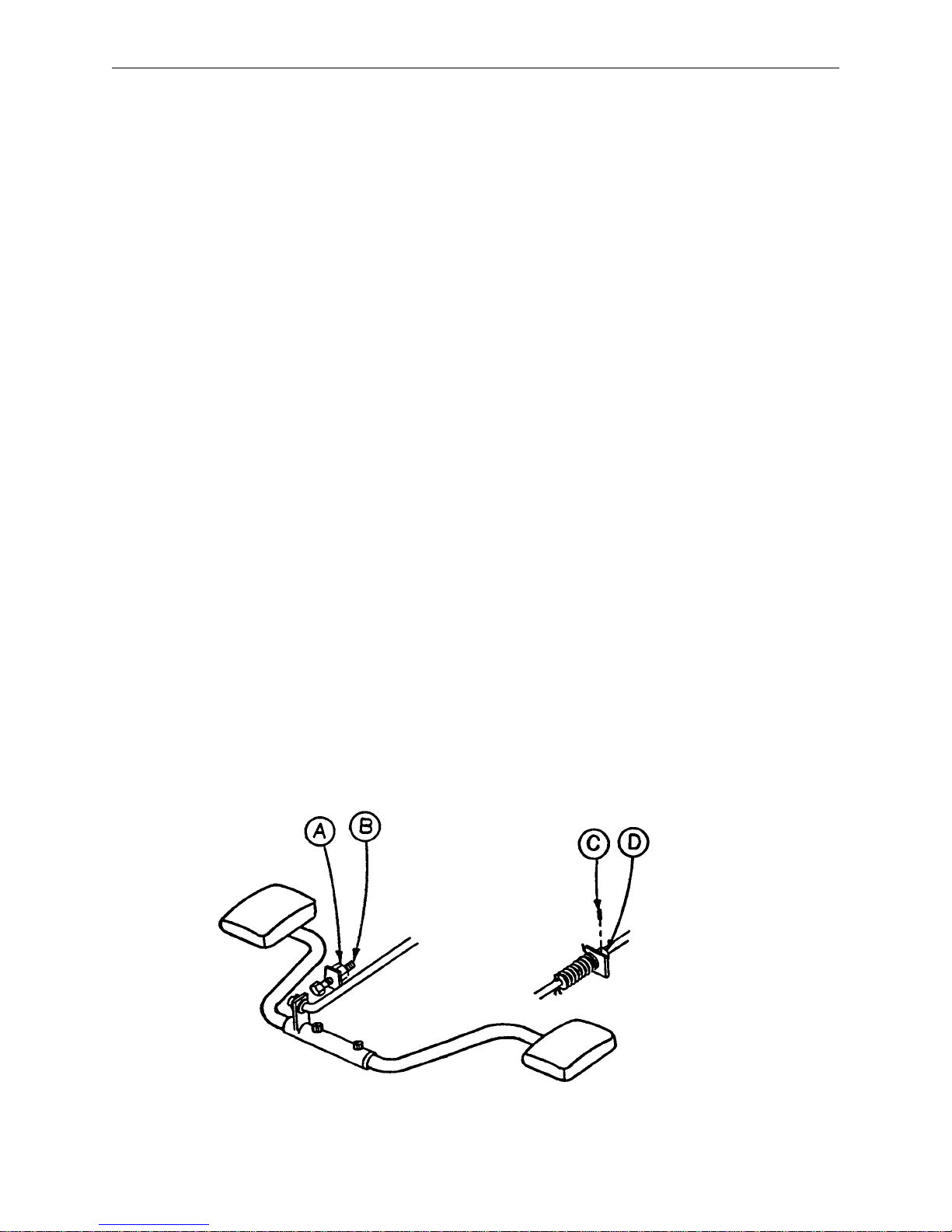
3. To adjust the foot end descent pedal, use a 5/32 hex Allen wrench to loosen the set screw (C) in the stop
collar (D) on the release rod. Hold the pedal parallel to the floor and slide the collar up to the bracket on
the release rod. Tighten the set screw on the stop collar. Be sure the head end and foot end descent
pedals are level with each other. Repeat for the head end pedal, if necessary.
4. Once the pedals are level, be sure the paddle on the end of the release rod for the foot end jack is slightly
touching the actuating stem on the jack base. If it is not, use a 3/32 hex Allen wrench to loosen the set
screw on the paddle hub. Adjust the paddle to JUST touch the stem of the jack. Tighten the set screw
in the paddle hub. Repeat for the head end jack, if necessary.
5. Depress the pedal for the foot end jack. The jack should start to descend about the same time the paddle
on the end of the rod contacts the sleeve on the jack actuating stem. The bracket on the foot pedal body
should hit the stop screw (B). Any further movement could cause damage to the stem components inside
the jack housing. To adjust the stop screw, use a 1/2 open end wrench to loosen the hex jam nut (A).
Turn the screw and re–tighten the hex jam nut. Repeat for the head end jack.
6. Pump the litter up to full height.
7. Step on both descent pedals at the same time. Both ends of the litter should lower with the foot end lower-
ing slightly faster than the head end. If it does not, refer to the procedure for adjusting the jack descent
rate.
8. Remove the wooden blocks supporting the base hood. Use the pedal cut–outs on the side of the hood
as a guide for proper re–positioning.
6
Service Information
PEDAL LINKAGE ADJUSTMENT – DUAL END CONTROL BASE
Required Tools:
7/16 Open End Wrench
1/2 Open End Wrench
(2) Wooden Blocks (10 – 12 inches in length)
Adjustment Procedure:
1. Pump the litter up to full height.
2. Lift the base hood, separating the hood from the base frame. Using the wooden blocks, support the base
hood.
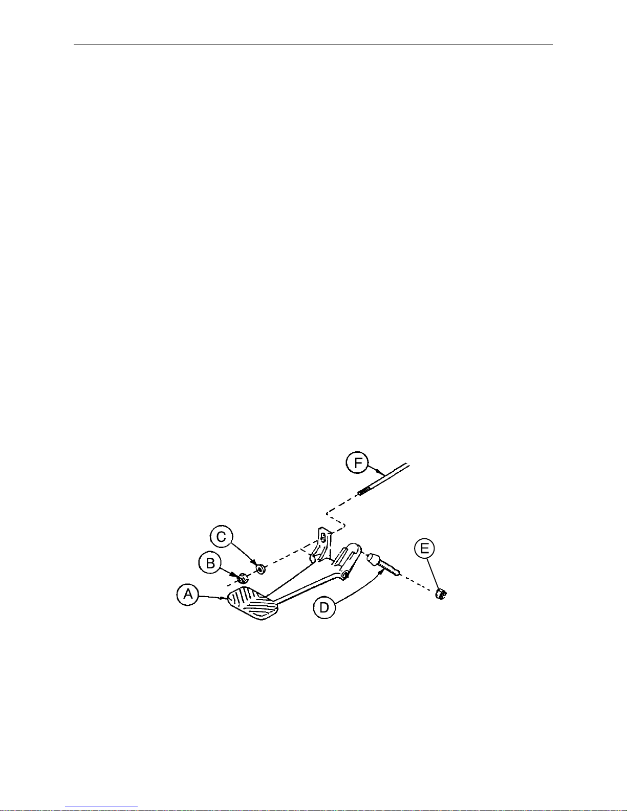
3. The descent pedals should be level with each other and there should be approximately 4 inches between
the floor and the bottom of the pedal. To raise the pedal height, use a 1/2 open end wrench to loosen the
hex jam nut (E). Using your hand, turn the screw (D) into the bracket. To lower the pedal height, loosen
the screw. Tighten the hex jam nut (E) after the correct height is achieved.
4. Once the pedals are level, the release rod can be adjusted. Using a 7/16 wrench, turn nut (B) clockwise
to shorten the release length and counterclockwise to increase the length.
5. Depress the pedal and be sure the jack descent is triggered when the pedal is approximately one inch from
the floor. The descent should stop when the pedal is released and the jack height should hold. Repeat
the above procedures for the descent pedal at the other end of the bed.
6. After adjusting each descent pedal individually, depress both pedals at the same time. Both jacks should
start descending when the pedals are approximately one inch from the floor. The foot end should lower
slightly faster than the head end. If it does not, see procedure for adjusting the jack descent rate.
7. Remove the wooden blocks supporting the base hood and secure the hood to the base frame.
7
Service Information
CASTER ASSEMBLY REPLACEMENT*
Required Tools:
1/8 Roll Pin Punch Drill with 1/8 inch Drill Bit
Flat Punch (any size larger than 1/8) Hammer
Needle Nose Pliers Floor Jack
3/4 Inch Wrench (2) Wooden Blocks (10 – 12 inches in length)
1 Inch Wrench Torque Wrench (w/ Ft. Lbs. Adjust.)
Replacement Procedure:
1. Pump the litter up to full height.
2. Lift the base hood, separating the hood from the base frame. Using the wooden blocks, support the base
hood.
3. Using a 1/8 roll pin punch and hammer, remove roll pin located in center of lug nut holding wheel assembly
to base frame.
4. Carefully remove plastic wheel covers.
5. Using a floor jack, lift base frame approximately 4 inches off the ground.
6. While holding cap screw with a 3/4 inch wrench, turn lug nut with a 1 inch wrench to loosen wheel assembly
from base frame. Remove wheel.
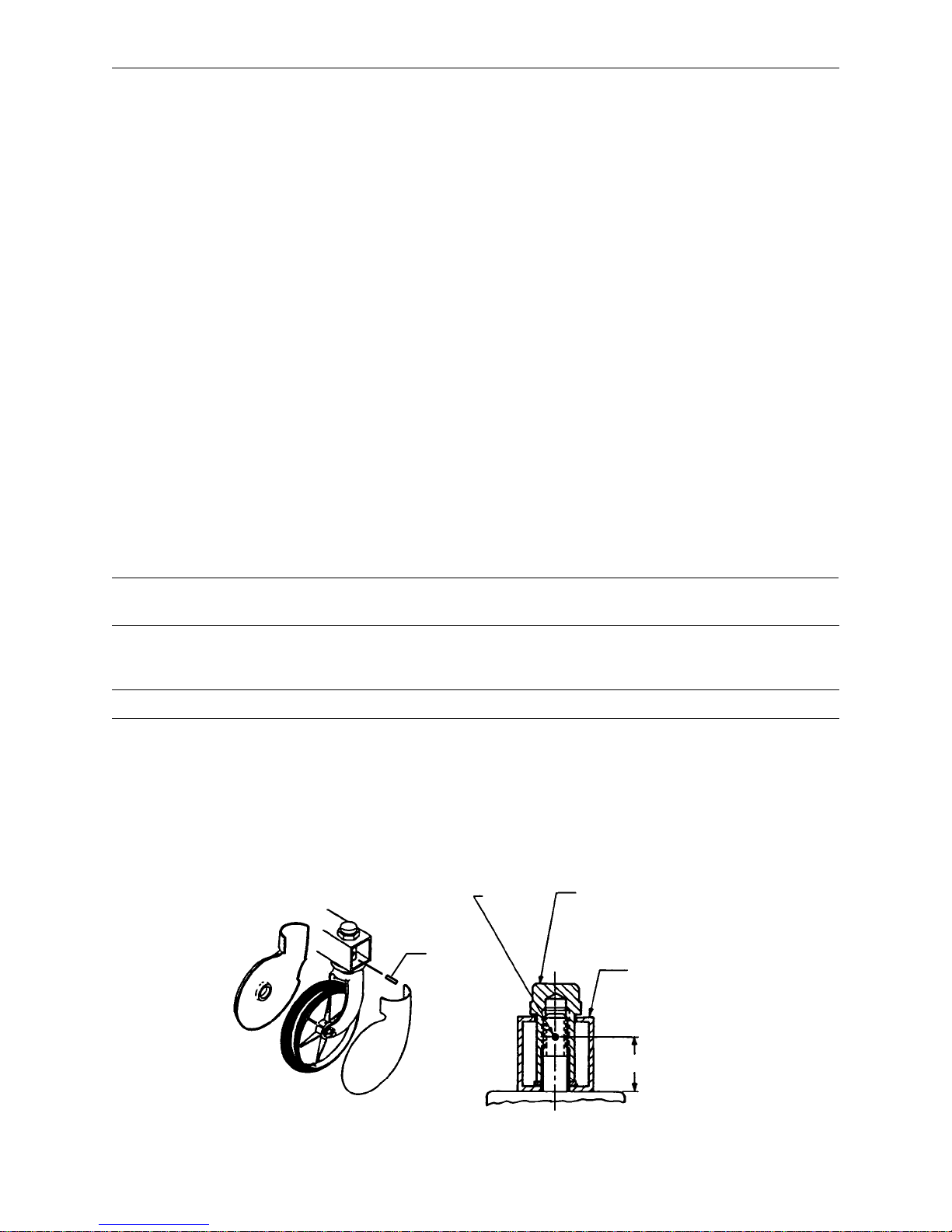
7. Install the new wheel assembly with new lug nut and tighten down to 60 – 65 foot–pounds torque.
WARNING
Never reuse the old lug nut, cap screw or roll pin once removed from base frame.
8. Lower the floor jack and set aside to be used, if needed, with another wheel.
9. Drill a 1/8 hole in center of lug nut, going completely through the lug nut.
CAUTION
Be careful not to ”oblong” the hole in the lug nut when drilling.
10. Using needle nose pliers, hold on to roll pin and tap into place. Finish driving roll pin with a flat head punch
and a hammer until flush with the lug nut.
11. Install plastic wheel covers onto wheel.
12. Remove the wooden blocks supporting the base hood and secure the hood to the base frame.
*Replacement Part Number 715–100–127 (Caster and Cover Assembly)
1/8 Inch
Dia.
Through
Roll Pin
Lug Nut
(60–65 Ft.–Lb.)
Support Tube
1 Inch
8

Service Information
HYDRAULIC SYSTEM TROUBLESHOOTING
NOTE
Be sure the pedal linkage has been adjusted properly before beginning service on the jacks (see page 6
or page 7).
PROBLEM/SYMPTOM SOLUTION
Jack will not raise to full height. Add hydraulic fluid (see p.10). Check for leaks.
Jack will not hold in raised position. Close the needle valve completely. If the jack
holds, replace valve #1 (see p. 14). If the jack
does not hold, replace valve #2 (see p. 15).
Jack will not pump up and the jack actuator rod
does not move.
Jack will not pump up but the jack actuator rod
does move when the pump pedal is activated.
Jack will not pump up and the jack actuator rod
may or may not move.
Close the needle valve. If the jack will now pump
up, replace valve #1. If the jack still will not pump
up after closing the needle valve, replace valve #3
(see p. 15).
Replace valve #2 (see p. 15).
Remove excess air (vacuum) in system (see p.
10).
Contact Stryker technical service at 1–800–327–0770 for further assistance.
9

Service Information
CHECKING HYDRAULIC FLUID LEVEL
Required Tools:
3/8 Open End Wrench
3/4 Open End Wrench
Procedure:
WARNING
To avoid personal injury or damage to the stretcher, remove the litter and the base hood before beginning
service on the jacks.
1. Using a 3/8 open end wrench, remove square head set screws from both head and foot end jack support
tubes. Remove litter top and set aside.
2. Lift base hood off base frame and set aside.
3. Be sure there are no hydraulic leaks. If there are, jack replacement will be necessary.
4. Lower the jack to the full down position.
5. Using a 3/4 open end wrench, slowly turn the fill plug located on the side of the reservoir counterclockwise
to allow excess system pressure to vent. Remove the fill plug.
6. The hydraulic fluid should be visible at the bottom of the fill hole. If it is not, add Mobil Aero HFA hydraulic
fluid (Stryker part number 2020–70–475) until the fluid is visible at the bottom of the fill hole. Replace the
fill plug.
CAUTION
Use of other types of oil may damage hydraulic units.
7. Replace the hood and the litter.
REMOVAL OF EXCESS AIR (VACUUM) FROM THE HYDRAULIC SYSTEM
Procedure:
1. Verify all hydraulic linkages are secure and operating properly (see pedal linkage adjustment procedure
page 6 or 7).
2. Using pump pedal, actuate system several times. This will force the air through the system and the jack
should now pump up.
10

Service Information
JACK DESCENT RATE ADJUSTMENT
Required Tools:
Screwdriver
(2) Wooden Blocks (10 – 12 inches in length)
Adjustment Procedure:
1. Pump the litter up to full height.
2. Lift the base hood, separating the hood from the base frame. Using the wooden blocks, support the base
hood.
3. The descent rate needle valve is located on the base of the jack. Turning the needle valve clockwise, with
a screwdriver, will decrease the rate of descent. Turning it counterclockwise will increase the rate of descent.
4. Adjust the needle valve so that the foot end of the stretcher descends slightly faster than the head end.
NOTE
The larger percentage of a patient’s weight is located in the torso area. Adjust descent rate accordingly.
5. Remove the wooden blocks supporting the base hood and secure the hood to the base frame.
NOTE
The jack descent rate was preset at the factory to drop the foot end faster than the head. It is recommended
that the foot drop faster to avoid patient disorientation.
11
Service Information
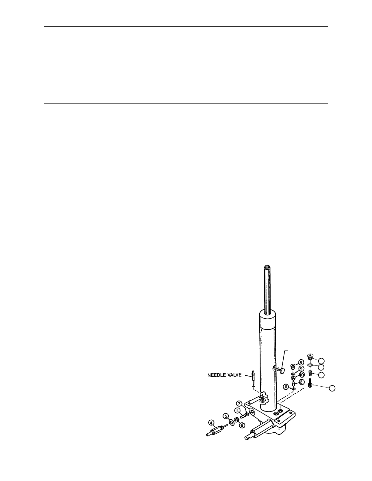
HYDRAULIC CHECK VALVE REPLACEMENT
Required Tools:
3/8 Open End Wrench Stiff Wire (with bent, pointed end) Small Needle Nose Pliers
3/4 Open End Wrench Torque Wrench (with Ft. Lbs. adjust.)
7/32 Hex Allen Wrench 1/2 Inch Diameter Rod
Replacement of Valve #1
WARNING
To avoid personal injury or damage to the stretcher, remove the litter and the base hood before beginning
service on the stretcher.
1. Using a 3/8 open end wrench, remove square head set screws from both head and foot end jack support
tubes. Remove litter top and set aside.
2. Lift base hood off base frame and set aside.
3. Lower the jack to full down position. The actuator must be manually lowered while depressing the appropri-
ate release pedal.
4. Remove the pin body assembly (4) with a 3/4 open end wrench and discard the housing gasket (5).
NOTE
Although the hydraulic fluid is not under pressure, some fluid loss will occur . The fluid loss should be minimal
but covering the floor is advisable.
5. Using a 7/32 hex Allen wrench, remove the valve plug (6).
6. Using a stiff wire with a bent, pointed end, remove and discard the valve (1) and the seal (7).
7. Install the new seal (7) flat to the bottom of its hole with a 1/2 inch diameter rod and install the new valve
(1) with the beveled end out (as shown in the illustration).
8. Install the valve plug (6) with the countersunk end first and the beveled end out. Tighten to 10 foot pounds
torque.
9. Install the pin body assembly (4) with the new housing gasket (5) and tighten to 10 foot pounds torque.
10. Pump up the jack to the maximum height. Apply weight to be sure the jack holds its position and there
are no hydraulic leaks before replacing the base hood and the litter.
ITEM PART NO. PART NAME
1 926–20–153 Check Valve
2 926–20–153 Check Valve
3 715–1–341 Poppet
4 715–100–312 Pin Housing Assembly*
715–270–100 Valve Assembly**
5 715–1–330 Housing Gasket
6 715–1–309 Valve Plug
7 926–20–154 Seal
8 715–1–101 Base Plug
9 926–20–156 Seal
10 715–1–309 Valve Plug
11 926–20–154 Seal
12 715–1–301 Base Plug
13 926–20–156 Seal
14 390–2–134 Conical Comp. Spring
* Used on jack part number 715–100–310.
** Used on jack part number 715–270–10.
(see label on side of jack reservoir for jack part number)
12
FILLER PLUG
12
13
14
3

Service Information
HYDRAULIC CHECK VALVE REPLACEMENT (CONT’D)
Replacement of Valve #2
WARNING
To avoid personal injury or damage to the stretcher, remove the litter and the base hood before beginning
service on the jacks. Lower the jack rod completely to relieve the pressure on the pump piston side of the
jack. This will prevent large hydraulic fluid loss and possible damage when the base plugs are removed.
1. Remove the base plug (8) and discard the seal (9).
2. Remove the valve plug (10).
3. Using a stiff wire with a bent, pointed end, remove the valve (2) and the seal (11) and discard the seal.
4. Install the new seal (11) flat to the bottom of its hole with a 1/2” diameter rod.
5. Install the new valve (2) with the beveled end out (as shown in the illustration).
6. Install the valve plug (10) and tighten to 10 foot–pounds torque.
7. Install the new seal (9) with the base plug (8) and tighten to 10 foot–pounds torque.
8. Pump up the jack to the maximum height.
9. Be sure there are no hydraulic leaks before replacing the base hood and the litter.
Replacement of Valve (Poppet) #3
WARNING
To avoid personal injury or damage to the stretcher, remove the litter and the base hood before beginning
service on the jacks. Lower the jack rod completely to relieve the pressure on the pump piston side of the
jack. This will prevent large hydraulic fluid loss and possible damage when the base plugs are removed.
1. Remove the base plug (12) and discard the seal (13).
2. Remove the compression spring (14).
3. Using a small needle nose pliers, remove the poppet (3).
4. Install the new poppet (3).
5. Install the compression spring (14).
6. Install the new seal (13) and the base plug (12) and tighten to 10 foot–pounds torque.
7. Pump up the jack to the maximum height to check its operation.
8. Check for hydraulic leaks before replacing the base hood and the litter.
13
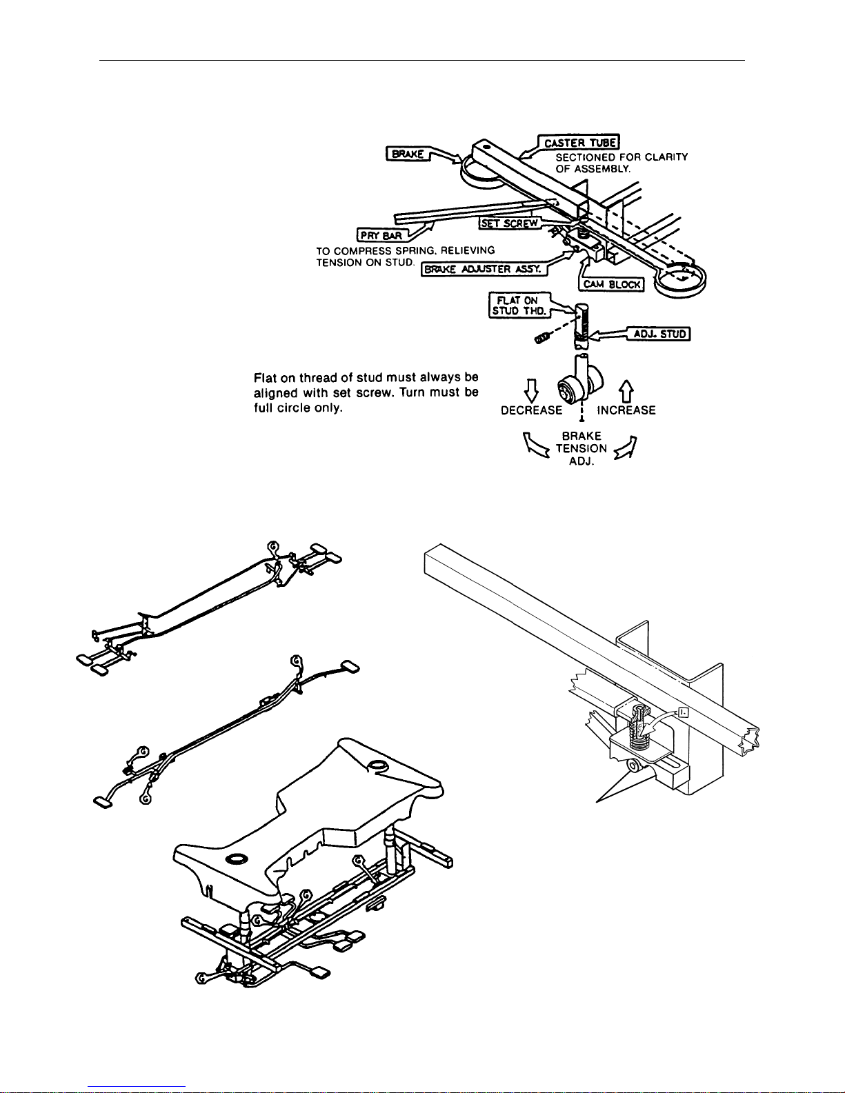
Required Tools:
3/32” Hex Allen Wrench
Pry Bar
Thread ”Locktite”
Service Information
BRAKE ADJUSTMENT
BASE LUBRICATION
Do not grease area shown.
1. Lubricate brake adjuster rod
around area shown with MPG–2
grease or equivalent.
14

Notes
15
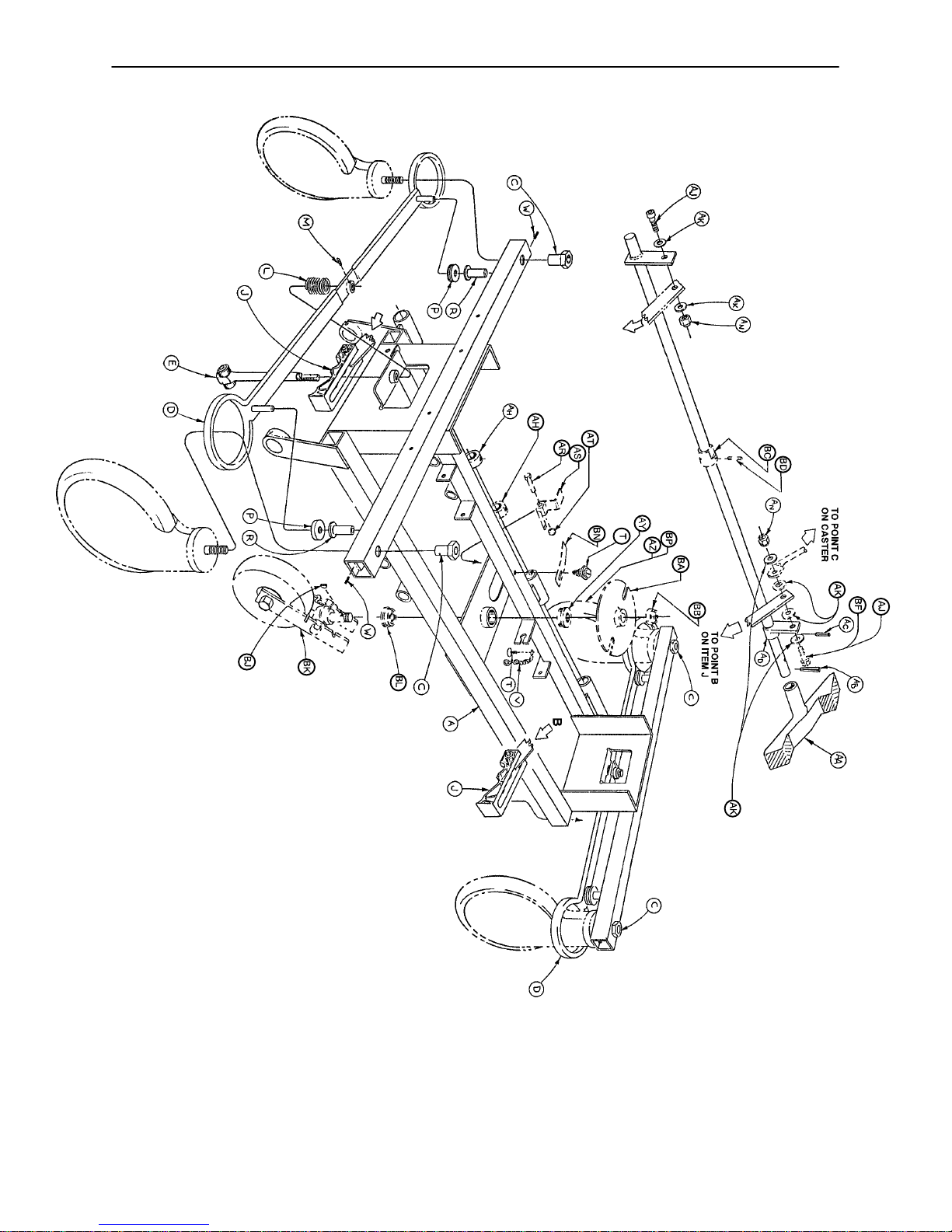
1066–45–19 Side Control Base Assembly (with Wheels)
Note:
Parts and assemblies drawn with broken
lines are optional accessories.
FOOT END
16
1066–45–19 Side Control Base Assembly (with Wheels)
Item Part No. Part Name Qty.
A 715–1–245 Base Weldment Assembly 1
B38–211 Spring 1
C 715–1–158 Caster Nut 4
D 715–1–61 Caster Brake Assembly 2
E (Page 18) Brake Adjuster Assembly 2
F 1066–1–34 Brake Rod Assembly 1
H 1000–10–62 Steering Lock Linkage Bar 1
J (Page 19) Brake Cam Assembly 2
L 715–1–94 Compression Spring 2
M21–50 Set Screw 2
P 715–1–11 Brake Cushion 4
R 946–1–116 Brake Bar Bushing 4
T23–25 Self–Tapping Screw 2
V 715–1–156 Grounding Chain 1
W26–5 Roll Pin 4
AA (Page 20) Pedal Ass’y, Brake and Steer, Ft. 2
AB 26–261 Groove Pin 2
AC 26–13 Roll Pin 1
AD 715–1–165 Actuator Plate Assembly 1
AH 42–20 Collar w/ Set Screw 2
AJ 8–17 Soc. Hd. Cap Screw 2*
AK 14–2 Nylon Washer 4
AN 16–2 Fiberlock Nut 2
AR 3–20 Hex Hd. Cap Screw 1
AS 715–1–217 Fifth Wheel Latch 1
AT 16–16 Nylock Nut 1
AY 715–1–157 Fifth Wheel Bearing 1
AZ (Page 21) Steering Caster Assembly 1**
BA 715–1–337 Fifth Wheel Plate Assembly 1
BB 16–49 Flexlock Nut 1
BC 715–1–161 Fifth Wheel Cam 1
BD 26–8 Roll Pin 1
BF 8–21 Soc. Hd. Cap Screw 1**
BJ 715–1–149 Woodruff Key 1
BK (Page 23) Fifth Wheel Assembly 1
BL 81–219 Bearing 1
BN 715–1–136 Fifth Wheel Spring 1
BP (Page 22) Caster Wheel Assembly 3 ***
*Item AJ to be used only when fifth wheel is ordered.
**Items AZ and BF to be used only when steerlock caster is ordered.
***Item BP quantity of four when fifth wheel is ordered.
STEERLOCK
ASSEMBLY
DETAIL
17
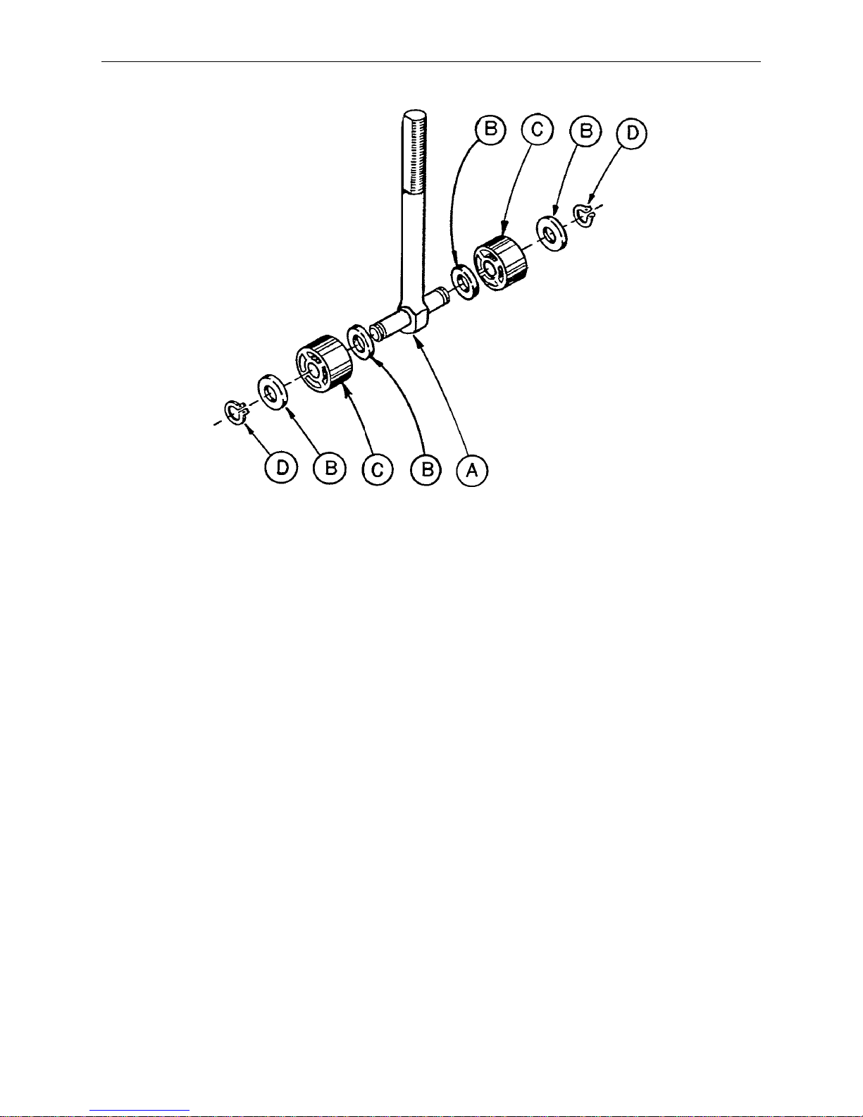
715–1–150 Brake Adjuster Assembly
Item Part No. Part Name Qty.
A 715–1–62 Threaded Stud Assembly 1
B14–4 Nylon Washer 4
C 715–1–180 Bearing 2
D28–8 Retaining Ring 2
18
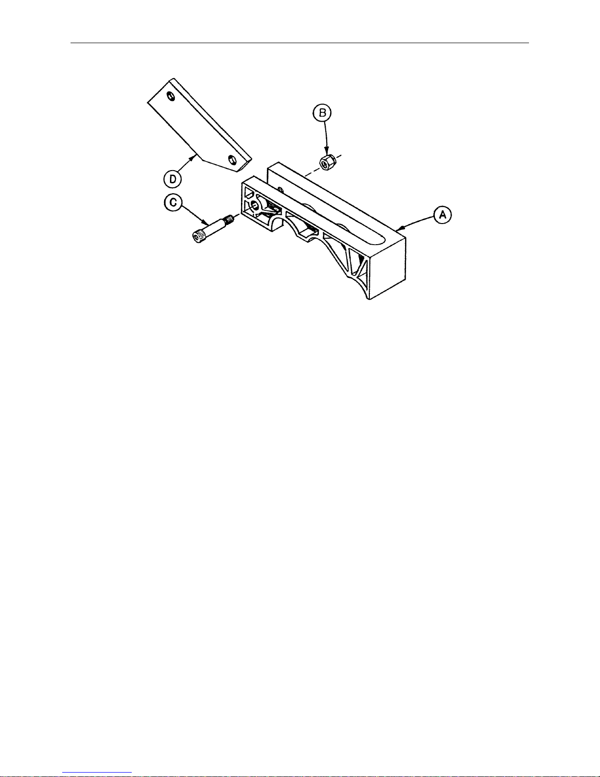
715–1–213 Brake Cam Assembly
Item Part No. Part Name Qty.
A 715–1–221 Brake Cam 1
B16–59 Fiberlock Nut 1
C8–21 Soc. Hd. Cap Screw 1
D 715–1–173 Brake Connecting Link 1
19
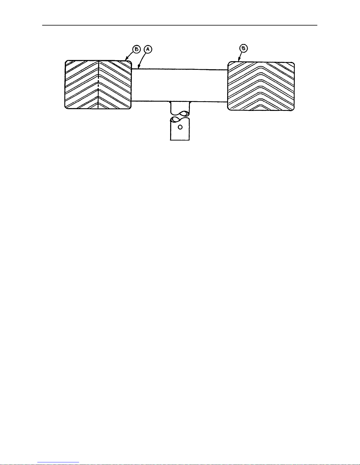
Brake Pedal Assembly, Side Control Base
Item Part No. Part Name Qty.
A 715–1–170 Brake Pedal Ass’y, Welded 1
B 715–1–145 Brake Pedal 2
20
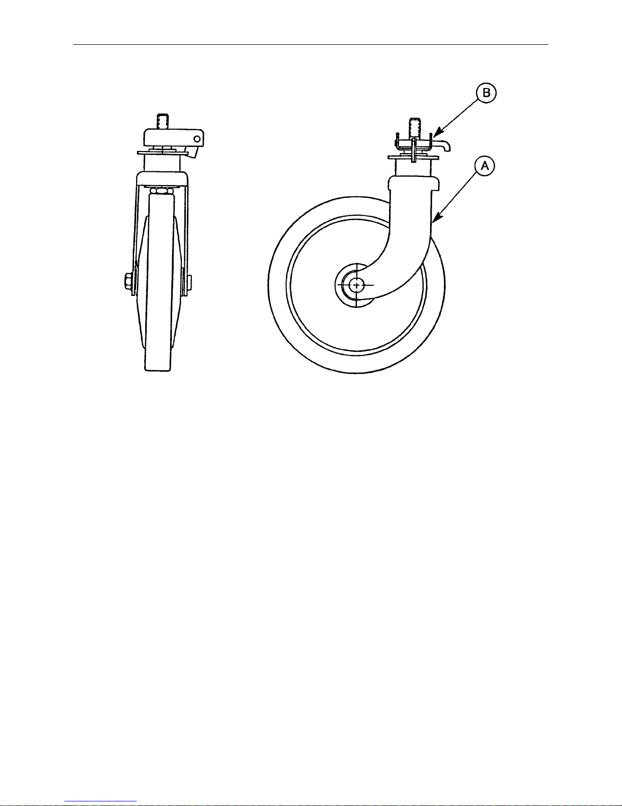
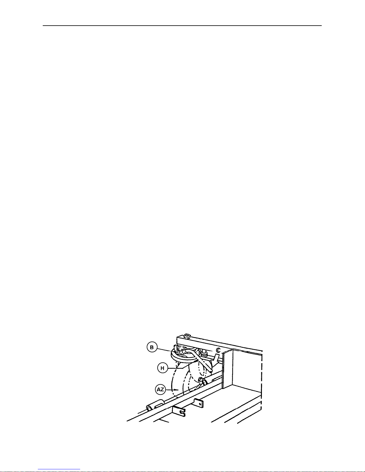
2020–46–220 Steering Caster Assembly
Item Part No. Part Name Qty.
A 946–1–279 Caster Assembly 1
B 1000–59–10 Latch Ass’y, Steer Caster 1
21
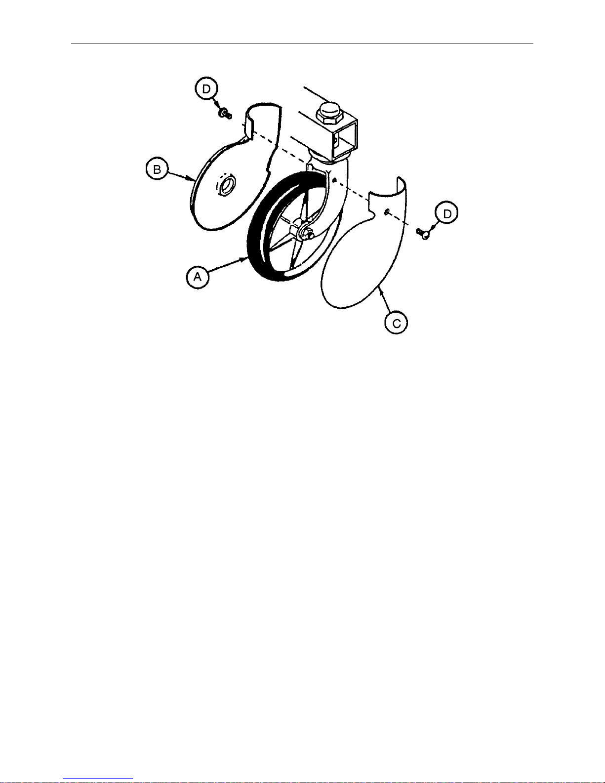
Caster and Caster Cover Assembly
Item Part No. Part Name Qty.
A 946–1–276 Caster Assembly 1
B 715–1–139 Caster Cover, Left 1
C 715–1–138 Caster Cover, Right 1
D23–59 Pan Hd. Self–Tapping Screw 2
22