

Page 1
2007/09 6208-001-701 Rev-B www.stryker.com
Instructions For Use
System 6
Sagittal Saw
REF 6208
US Patents: 5,263,972; 5,747,953; 6,013,991
Page 2
2 www.stryker.com
2007/09 6208-001-701 Rev-B
Intended Use
The Stryker System 6 Battery Powered Heavy Duty Sagittal Saw is an oscillating cutting device used for cutting
bone and bone related tissue.
DESCRIPTION REF
Large Battery Pack ...................................................6215
Accessory Information*
*Contact your Stryker sales representative for a complete list of additional accessories.
WARNINGS:
• Use only Stryker-approved components and accessories, unless otherwise specified. Other accessories
may result in increased electromagnetic emissions or
decreased electromagnetic immunity of the system.
DO NOT modify any component or accessory. Failure
to comply may result in patient and/or health care
staff injury.
• ALWAYS use Stryker sagittal saw blades with this
handpiece. Failure to comply may result in patient
and/or health care staff injury.
Important Information
The words WARNING, CAUTION and NOTE have special
meaning and should be reviewed.
WARNING:
Disregarding WARNING information
may compromise the safety of the
patient and/or health care staff and
may result in injury.
CAUTION:
Disregarding CAUTION information
may compromise product reliability
and may result in damage.
NOTE:
NOTE information supplements and/
or clarifies procedural information.
A triangle with an exclamation point
alerts the health care professional to
read and understand the accompanying instructions, especially the
operating, maintenance, and safety
information.
Page 3

6208-001-701 Rev-B 2007/09
www.stryker.com 3
User/Patient Safety*
WARNINGS:
• Only trained and experienced health care professionals should use this equipment. Before using any
system component or any component compatible
with this system, read and understand the instructions. Pay special attention to WARNING information.
Become familiar with the system components prior
to use. Failure to comply may result in patient and/or
health care staff injury.
• Upon initial receipt and before each use, operate the
equipment and inspect each component for damage.
DO NOT use any component if damage is apparent.
Failure to comply may result in patient and/or health
care staff injury.
• Perform recommended periodic maintenance as
indicated in the instructions for use. Only trained
and experienced health care professionals should
maintain this equipment.
• Clean and sterilize handpieces and batteries before
first and every use.
• DO NOT use this equipment in the presence of a
mixture consisting of flammable anesthetic and air or
with oxygen or nitrous oxide.
• Take special precautions regarding electromagnetic
compatibility (EMC) when using medical electrical equipment like the handpiece. Install and place
the handpiece into service according to the EMC
information in this manual. Portable and mobile RF
communications equipment can affect the function of
the handpiece.
• ALWAYS place the handpiece in the safe mode while
the handpiece is idle, before installing or removing
any accessory, or when passing the handpiece to another person. Failure to comply may result in patient
and/or health care staff injury.
• DO NOT apply excessive pressure, such as bending
or prying, with a cutting accessory to prevent fracturing the accessory. Failure to comply may result in
patient and/or health care staff injury.
• DO NOT reuse single use cutting accessories. Failure
to comply may result in patient and/or health care
staff injury.
*If you need more information, contact your Stryker sales representative or call Stryker customer service at 1-800-253-3210. Outside
the US, contact your nearest Stryker subsidiary.
Page 4
4 www.stryker.com
2007/09 6208-001-701 Rev-B
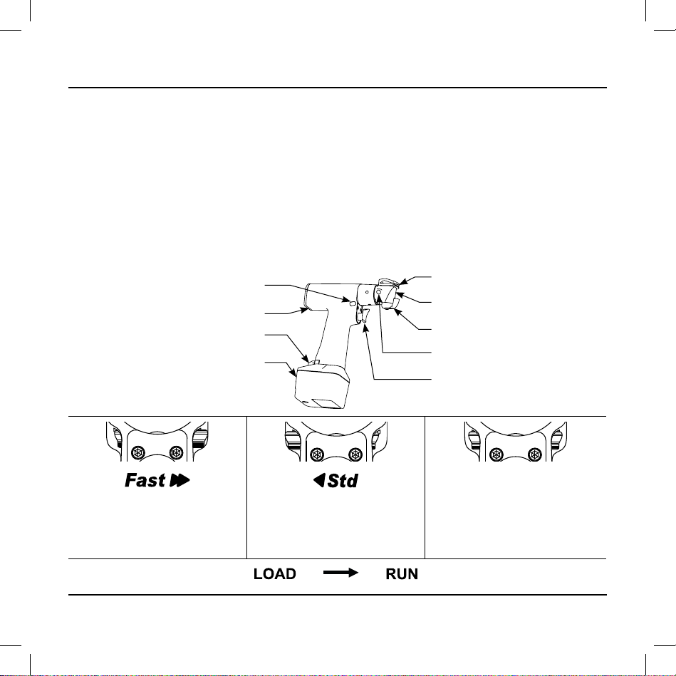
Features
• Battery Latch - To release the battery pack from the handpiece, depress the battery latch.
• Battery Pack - Rechargeable battery pack that provides power to the handpiece.
• Index Button - To allow the indexing of the sagittal head, push the index button.
• Blade Mount Lever- Rotate the lever to the LOAD or RUN position to install or lock the blade into place.
• Blade Retainer - The retainer holds the blade.
• Sagittal Head - The sagittal head may be indexed in 45° increments and can turn in a complete 360° rotation to
achieve the desired cutting angle.
• Trigger Switch - The trigger is pressure sensitive for variable speed operation.
• FAST/STD/Safe Control - Based on its position, allows the handpiece to operate in the FAST or STD mode; the
safe mode prevents operation of the handpiece.
• Accessory Interface - Connector provides power and communication for future accessories.
Symbol Definitions
Slide the FAST/STD/Safe control to the
FAST position to allow the handpiece to
operate at high torque and high speed
when the trigger is depressed.
Slide the FAST/STD/Safe control to the
STD (standard) position to allow the
handpiece to operate at high torque and
standard speed when the trigger switch
is depressed.
Slide the FAST/STD/Safe control to
the safe position to lock the trigger and
prevent inadvertent operation of the handpiece; the handpiece cannot be operated.
The LOAD position allows the insertion of
the blade into the handpiece.
The RUN position locks the blade in the
handpiece.
Battery Pack
Sagittal Head
Blade Retainer
Index Button
Trigger Switch
Battery Latch
Blade Mount Lever
FAST/STD/Safe Control
Accessory Interface
Page 5
6208-001-701 Rev-B 2007/09
www.stryker.com 5
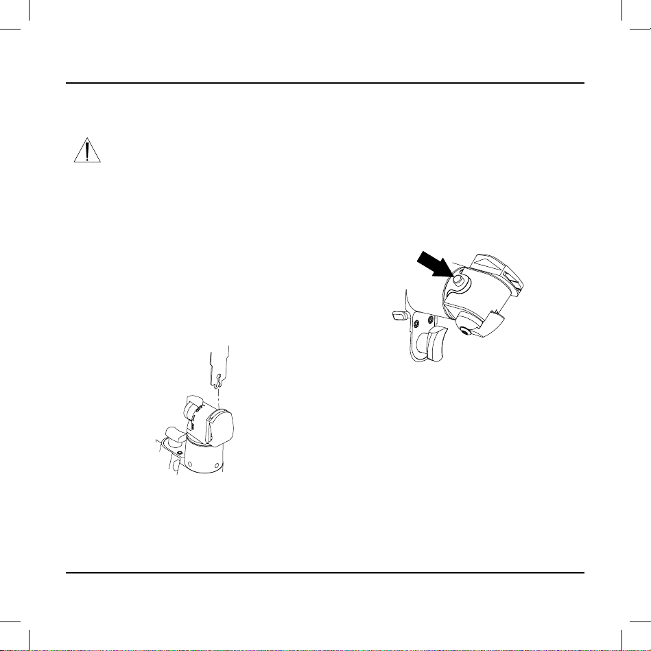
To Install Cutting Accessory
Figure 1 To Install Blade Rotate the Lever
Instructions
Figure 2 To Index Head Push the Button
To Index Sagittal Head
NOTE: The sagittal head has eight possible cutting
angle positions (45° increments).
Push and hold the index button; rotate the sagittal
head to the desired cutting angle (see figure 2).
1.
Slide the FAST/STD/Safe control to the safe position.
Rotate the blade mount lever to the LOAD position.
Hold the handpiece in a vertical orientation with the
sagittal head and blade entry slot facing up. (see
figure 1).
Insert the blade into the slot. Ensure the full insert
line of the blade disappears in the blade retainer
indicating the blade is positioned properly.
1.
2.
3.
4.
Once the sagittal head is positioned, release the
index button, and gently turn the sagittal head to
ensure it is locked into position.
2.
WARNING: To prevent the inadvertent
running of the handpiece, ALWAYS place
the FAST/STD/safe control in the safe
position before installing or removing any
accessory.
Rotate the blade mount lever to the RUN position
while maintaining the vertical orientation of the handpiece to lock the blade.
Gently tug the blade to ensure it is secure.
5.
6.
CAUTION: Before operating the handpiece, ensure
the sagittal head is locked into position. Failure to
comply may result in product damage.
Page 6

6 www.stryker.com
2007/09 6208-001-701 Rev-B
Instructions (cont’d)
To Install Battery Pack To Operate Handpiece
Slide a fully charged battery pack firmly into the
handpiece until the battery latch snaps, indicating the
battery pack is secure (see figure 3).
1.
Figure 3 Install Battery Pack
Test the operation of the handpiece by sliding the
FAST/STD/Safe control to the FAST or STD positions
and squeezing the trigger.
Slide FAST/STD/Safe control to the safe position
until you are ready to use the handpiece.
2.
3.
NOTES:
• This handpiece is designed to accept the Stryker
Large Battery Pack REF 6215 only. This battery
pack can be charged in the Stryker System 6 Battery
Charger REF 6110-120 configured with the appropriate battery charger module.
• See the instructions supplied with the battery charger
and/or battery pack for charging details and specifications.
WARNING: ALWAYS place the FAST/
STD/Safe control in the safe position while
the handpiece is idle, before installing or
removing an accessory, or when passing
the handpiece to another person. Failure to
comply may result in patient and/or health
care staff injury.
CAUTIONS:
• When operating the handpiece, let the blade do the
cutting. Applying too much pressure will bend the
blade and reduce the cutting quality.
• DO NOT stall the handpiece. Failure to comply may
damage the electric motor and/or battery pack. If
the handpiece jams, release the trigger immediately.
Remove any obstructions before continuing the procedure.
• If any power loss is experienced while using a handpiece, ALWAYS replace the battery pack with a fully
charged battery pack. Failure to comply may result in
a drained or damaged battery pack with a shortened
life.
Slide the FAST/STD/Safe control to the FAST or STD
position to allow the handpiece to operate.
Squeeze the pressure sensitive trigger for variable
speed operation.
Slide the FAST/STD/Safe control to the safe position
when you are finished operating the handpiece.
1.
2.
3.
Page 7

6208-001-701 Rev-B 2007/09
www.stryker.com 7
To Remove Battery Pack
Depress the battery latch and pull the battery pack out.
To Remove Cutting Accessory
Rotate the blade mount lever to the LOAD position and
remove the blade.
Periodic Maintenance
INTERVAL ACTIVITY
Prior to each use. Inspect, operate and test the hand-
piece to ensure that it is working
properly. Ensure that there are no
loose or missing components. Check
all moving parts for free movement.
Be alert for unusual sounds or vibrations and note the operating speed.
Storage and Handling
To ensure the longevity, performance and safety of this
equipment, use the original packaging materials when
storing or transporting this equipment.
Page 8

8 www.stryker.com
2007/09 6208-001-701 Rev-B
Troubleshooting Guide*
PROBLEM CAUSE ACTION
Handpiece does not run or
oscillates at a reduced speed
making cutting difficult.
Battery pack is discharged. Recharge the battery pack in Stryker charger.
FAST/STD/Safe control is in STD
position.
Set the FAST/STD/Safe control to the FAST position.
Battery pack is expended. Replace the battery pack.
FAST/STD/Safe control is in the
safe position.
Set the FAST/STD/Safe control to the FAST or STD
position.
Drivetrain is malfunctioning. Return the handpiece for repair.
Motor runs but blade does not
move.
Drivetrain is malfunctioning. Return the handpiece for repair.
Battery pack becomes unusually hot during use.
Circuitry is malfunctioning. Check the battery pack on the charger. Replace the bat-
tery pack if required. See the instructions supplied with
the battery charger.
Blade will not fit into the blade
retainer or cannot be secured.
Debris is inside the end of the
blade retainer.
Clean the handpiece with a small brush.
Blade is not a Stryker product. Use a Stryker blade.
Blade retainer is damaged. Return the handpiece for repair.
Handpiece has become noisy
and vibrates.
Blade is not a Stryker product. Use a Stryker blade.
Drivetrain is malfunctioning. Return the handpiece for repair.
Sporadic electrical interference
is experienced.
Electrical noise is present.
Turn off all electrical equipment not in use in the operating room.
Relocate electrical equipment; increase spatial distance.
Plug operating room equipment into different operating
room outlets.
*DO NOT service this equipment. If you require service, contact your Stryker sales representative or call Stryker customer service
at 1-800-253-3210. Outside the US, contact your nearest Stryker subsidiary.
Page 9

6208-001-701 Rev-B 2007/09
www.stryker.com 9
To Drain Water From Handpiece
Remove the battery pack and cutting accessory from
the handpiece.
Using a brush with stiff, non-metallic bristles and
hospital enzymatic cleaner, scrub the debris from the
handpiece. Pay special attention to crevices and hard
to reach areas such as seams, joints, and details
around the blade retainer, trigger, and connector
areas.
Rinse all external surfaces of the handpiece under
running water. Hold the handpiece upright to prevent
water from running into the battery contact area.
If water leaks into the handpiece, tip the handpiece
back as shown to allow drainage from a small opening in the battery contact area.
1.
2.
3.
4.
To Clean Handpiece
Visually inspect the handpiece for any remaining
debris; if any debris is present, repeat the cleaning
and rinsing procedure using fresh hospital enzymatic
cleaner.
Dry the handpiece with a lint-free towel.
After cleaning, sterilize as directed. See Sterilization
Recommendations.
5.
6.
7.
To Clean Battery Packs and Accessories
See the care instructions supplied with the battery
packs, battery pack modules and battery charger.
Cleaning Recommendations
WARNINGS:
• Clean and sterilize handpieces, and batteries before
first and every use.
• Prior to cleaning and sterilization, remove all accessories from the handpieces.
• DO NOT use solvents, lubricants, or other chemicals
unless otherwise specified.
CAUTIONS:
• DO NOT immerse a handpiece or battery pack in
liquid. Moisture may enter the equipment, cause corrosion, and damage the electrical and/or mechanical
components.
• DO NOT allow liquid to run directly into any electrical
connection. Moisture may cause corrosion to electrical and/or mechanical components.
Page 10

10 www.stryker.com
2007/09 6208-001-701 Rev-B
Sterilization Recommendations*
WARNINGS:
• Clean and sterilize handpieces and batteries before
first and every use.
• Prior to cleaning and sterilization, remove all accessories from the handpieces.
To obtain optimal performance and prevent damage,
perform one of the following sterilization procedures:
“Flash” Autoclave:
• Gravity displacement sterilizer
• 270-272 °F (132-134 °C)
• Unwrapped in an instrument tray
• 10-minute minimum exposure time
Hi Vac:
• Pre-vacuumed sterilizer
• 270-272 °F (132-134 °C)
• Wrapped or unwrapped
• 4-minute minimum exposure time
• 8-minute minimum dry time
To Sterilize Battery Packs
See the care instructions supplied with the battery
packs.
ETO:
• 100% ETO
• 120-135 °F (49-57 °C)
• Wrapped in an instrument tray or fully perforated
sterilization box
• 2-hour 30-minute exposure time, 8-hour minimum
aeration time
250 °F Gravity:
• Gravity displacement sterilizer
• 250-254 °F (121-123 °C)
• Wrapped in an instrument tray or fully perforated
sterilization box
• 50-minute exposure time
• 8-minute minimum drying time
270 °F Gravity:
• Gravity displacement sterilizer
• 270-272 °F (132-134 °C)
• Wrapped in an instrument tray or fully perforated
sterilization box
• 35-minute minimum exposure time
• 8-minute minimum dry time
*Validation is based on the Association for the Advancement of
Medical Instrumentation (AAMI) protocol.
To Sterilize Handpieces
NOTE: After sterilization, allow the equipment to cool
to room temperature to ensure a comfortable operating
temperature.
Page 11

6208-001-701 Rev-B 2007/09
www.stryker.com 11
Specifications*
Model: REF 6208 Sagittal Saw
Size: 8.5 in. [216 mm] height (with large battery pack)
1.5 in. [38 mm] width
6.4 in. [163 mm] length
Weight: 3.5 lbs. [1.58 kg] (with large battery pack)
Speed: 12,000 CPM (FAST mode); 10,000 CPM (STD mode)
Excursion: 5° arc
Duty Cycle:
Intermittent Operation - 1 minute on / 4 minutes off 5 times with a 3 hour rest
Approval: CSA International
CAN/CSA-C22.2 No. 601.1-M90
UL 60601-1
IEC 60601-1
Equipment Type:
Type BF Applied Part
Power Supply: Internally Powered 9.6 V
Enclosure Protection: IPX0 Ordinary Equipment
Environmental Conditions: Operation Storage and Transportation
Temperature:
Relative Humidity:
Atmospheric Pressure:
*Specifications are approximate and may vary from unit to unit or as a result of power supply fluctuations.
Page 12

12 www.stryker.com
2007/09 6208-001-701 Rev-B
Guidance and manufacturer's declaration - electromagnetic emissions
The System 6 handpiece is intended for use in the electromagnetic environment specified below. The customer or the user of the
System 6 handpiece should assure that it is used in such an environment.
Emissions test Compliance Electromagnetic environment - guidance
RF emissions
CISPR 11
Group 1 The System 6 handpiece uses RF energy only for its internal function.
Therefore, its RF emissions are very low and are not likely to cause any
interference in nearby electronic equipment.
RF emissions
CISPR 11
Class B The System 6 handpiece is suitable for use in all establishments, includ-
ing domestic establishments and those directly connected to the public
low-voltage power supply network that supplies buildings used for domestic
purposes.
Harmonic emissions
IEC 61000-3-2
n/a
Voltage fluctuations/
flicker emissions
IEC 61000-3-3
n/a
Specifications (cont’d)
Page 13

6208-001-701 Rev-B 2007/09
www.stryker.com 13
Guidance and manufacturer's declaration - electromagnetic immunity
The System 6 handpiece is intended for use in the electromagnetic environment specified below. The customer or the user of the
System 6 handpiece should assure that it is used in such an environment.
Immunity test IEC 60601 test level Compliance level Electromagnetic environment - guidance
Conducted RF
IEC 61000-4-6
3 Vrms
150 kHz to 80 MHz
n/a
n/a
Portable and mobile RF communications equipment
should be used no closer to any part of the System 6
handpiece, including cables, than the recommended sep-
aration distance calculated from the equation applicable
to the frequency of the transmitter.
Recommended separation distance
d=1.67√P
d=1.67√P
80 MHz to 800 MHz
d=2.33√P
800 MHz to 2.5 GHz
Where P is the maximum output power rating of the
transmitter in watts (W) according to the transmitter
manufacturer and d is the recommended separation
distance in meters (m)
Interference may occur in the vicinity of equipment
marked with the following symbol:
Radiated RF
IEC 61000-4-3
3 V/m
80 MHz to 2.5 GHz
3 V/m
80 MHz to 2.5 GHz
NOTE 1: At 80 MHz and 800MHz the higher frequency range applies.
NOTE 2: These guidelines may not apply in all situations. Electromagnetic propagation is affected by absorption and reflection
from structures, objects and people.
Specifications (cont’d)
Page 14

14 www.stryker.com
2007/09 6208-001-701 Rev-B
Guidance and manufacturer's declaration - electromagnetic immunity
The System 6 handpiece is intended for use in the electromagnetic environment specified below. The customer or the user of the
System 6 handpiece should assure that it is used in such an environment.
Immunity test IEC 60601 test level Compliance level Electromagnetic environment -
guidance
Electrostatic discharge (ESD)
IEC 61000-4-2
±6 kV contact
±8 kV air
±2, 4, 6 kV contact
±2, 4, 8 kV air
Floors should be wood, concrete or
ceramic tile. If floors are covered with
synthetic material, the relative humidity
should be at least 30%.
Electrical fast transient/burst
IEC 61000-4-4
±2 kV for power supply lines
±1 kV for input/output lines
n/a
n/a
Surge
IEC 61000-4-5
±1 kV differential mode
±2 kV common mode
n/a
n/a
Voltage dips, short interruptions
and voltage variations on power
supply input lines
IEC 61000-4-11
<5% U
T
(>95% dip in UT )
for 0,5 cycle
n/a
40% U
T
(60% dip in UT)
for 5 cycles
n/a
70% UT
(30% dip in UT)
for 25 cycles
n/a
<5% U
T
(>95% dip in UT )
for 5 sec
n/a
Power frequency (50/60 Hz)
magnetic field
IEC 61000-4-8
3 A/m 3 A/m Power frequency magnetic fields
should be at levels characteristics of a
typical location in a typical commercial
or hospital environment.
NOTE:
UT is the alternating current mains voltage prior to application of the test level.
Specifications (cont’d)
Page 15

6208-001-701 Rev-B 2007/09
www.stryker.com 15
Recommended separation distances between portable and mobile RF communications
equipment and the System 6 handpiece
The System 6 handpiece is intended for use in the electromagnetic environment in which radiated RF disturbances are controlled.
The customer or the user of the System 6 handpiece can help prevent electromagnetic interference by maintaining a minimum
distance between portable and mobile RF communications equipment (transmitters) and the System 6 handpiece as recommend-
ed below, according to the maximum output power of the communications equipment.
Rated maximum output power
of transmitter
W
Separation distance according to frequency of transmitter
m
150 kHz to 80 MHz 80 MHz to 800 MHz 800 MHz to 2.5 GHz
0.01 n/a 0.12 0.23
0.1 n/a 0.37 0.74
1 n/a 1.17 2.33
10 n/a 3.70 7.37
100 n/a 11.70 23.30
For transmitters rated at a maximum output power not listed above, the recommended separation distance d in meters (m) can be
estimated using the equation applicable to the frequency of the transmitter, where P is the maximum output power rating of the
transmitter in watts (W) according to the transmitter manufacturer.
NOTE 1: At 80 MHz and 800MHz, the separation distance for the higher frequency range applies.
NOTE 2: These guidelines may not apply in all situations. Electromagnetic propagation is affected by absorption and reflection
from structures, objects and people.
Specifications (cont’d)
Page 16

2007/09 6208-001-701 Rev-B www.stryker.com
Stryker Instruments
4100 E. Milham
Kalamazoo, Michigan
(USA) 49001
1-269-323-7700
1-800-253-3210
Stryker France
ZAC Satolas Green Pusignan
Av. de Satolas Green
69881 MEYZIEU Cedex
France
ES/DE/FR/IT/NL 6208-001-711
JA/ZH/KO 6208-001-721
SV/DA/FI/PT/NO 6208-001-731
EL/PL 6208-001-751
 Loading...