

Page 1

MX-PRO® R3
6082
Operations/Maintenance Manual
2013/02 A.0 6082-209-001 REV A www.stryker.com
Page 2

Page 3

Table of Contents
Introduction .............................................................................6
Specifications ........................................................................6
Warning / Caution / Note Definition.........................................................7
Product Illustration ........................................................................8
Symbols and Definitions ....................................................................9
Warranty ..............................................................................10
Stryker EMS Return Policy ..............................................................11
Return Authorization...................................................................11
Damaged Merchandise ................................................................11
International Warranty Clause............................................................11
Patent Information ....................................................................11
Summary of Safety Precautions .............................................................12
Setup Procedures........................................................................14
Vehicle Safety Hook Selection ..............................................................15
Vehicle Safety Hook Installation .............................................................16
Vehicle Configuration..................................................................16
Required Hardware for Installation of the Safety Hook (Not Supplied) ..............................16
Front to Back Positioning of the Safety Hook ................................................17
Side to Side Positioning of the Safety Hook .................................................18
Installing the Safety Hook...............................................................18
Cot Positions ...........................................................................19
Cot Operations..........................................................................20
Using Patient Restraint Straps ...........................................................20
Pedi-Mate® Infant Restraint System Attachment Instructions (Optional Equipment) ....................22
Operating Guidelines ..................................................................24
Transferring the Patient to the Cot ........................................................24
Rolling the Cot ......................................................................24
Raising/Lowering the Cot ..............................................................24
Loading the Cot into a Vehicle with Two Operators ............................................25
Loading an Empty Cot into a Vehicle with One Operator ........................................26
Unloading The Cot From a Vehicle with Two Operators .........................................27
Unloading an Empty Cot From a Vehicle with One Operator .....................................27
Using Additional Assistance .............................................................28
Operating the Optional Wheel Lock(s) .....................................................29
Adjusting the Wheel Locking Force........................................................30
Changing the Cot Height with Two Operators ................................................31
Changing The Height of an Empty Cot With One Operator ......................................32
Adjusting the Leg Rest.................................................................33
Operating the Backrest ................................................................34
Operating the Siderails.................................................................34
Operating the Breakaway Head Section ....................................................35
Operating the Two-Stage I.V. Pole (Optional Equipment) ........................................36
Operating the Three-Stage I.V. Pole (Optional Equipment).......................................37
www.stryker.com 6082-209 -001 REV A 3
Page 4

Table of Contents
Cleaning...............................................................................38
Washing Limitations ...................................................................38
Removal of Iodine Compounds ...........................................................39
Preventative Maintenance ..................................................................40
Checklist ...........................................................................40
Base Lubrication .....................................................................41
Pneumatic Backrest Adjustment ..........................................................42
Maintenance Record......................................................................43
Training Record .........................................................................44
Cot Assembly ...........................................................................45
Base Assembly..........................................................................51
Wheel Assembly - 6060-002-010 ............................................................55
Base Pivot Outer Lift Tube Assembly - 6082-201-067..............................................56
Base Pivot Inner Lift Tube Assembly - 6082-001-069 ..............................................57
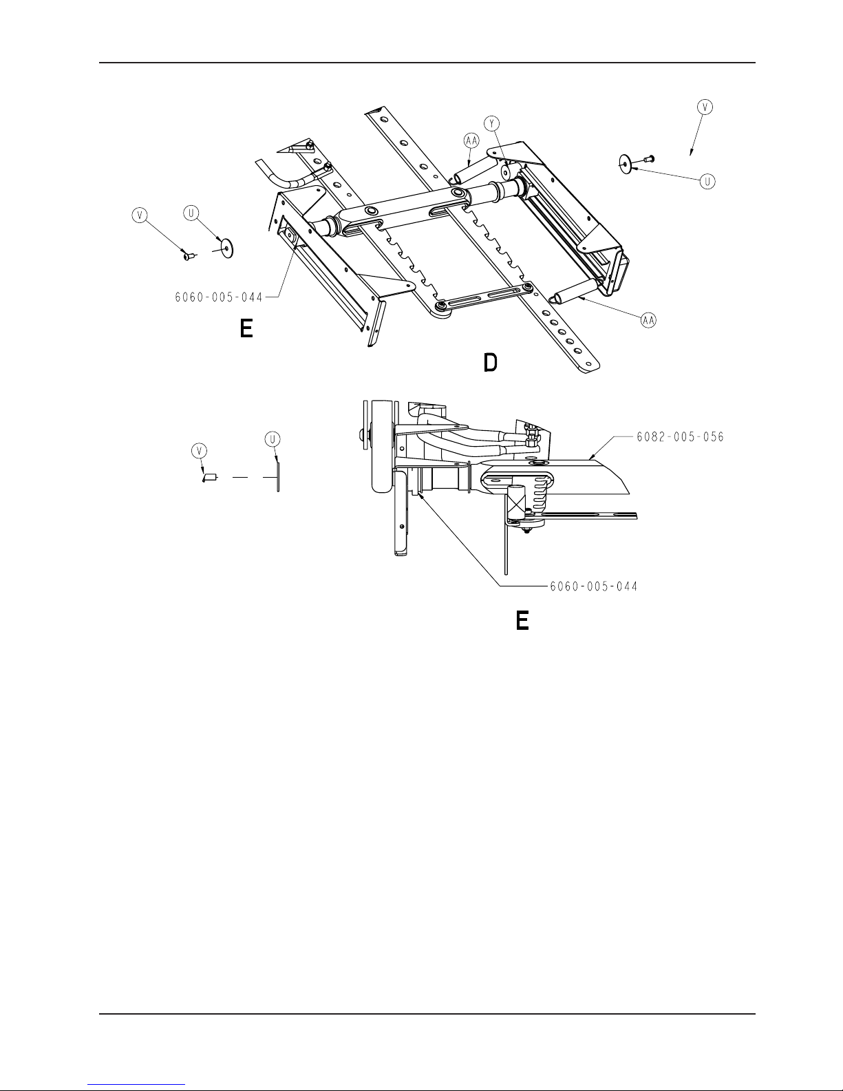
Lock Bar Assembly - 6082-005-056 ..........................................................58
Adjustable Caster Lock Assembly - 6082-200-010 ................................................59
Optional Single Wheel Lock Assembly - 6082-501-010.............................................60
Optional Dual Wheel Lock Assembly - 6082-502-010..............................................60
No Wheel Lock Option ....................................................................61
Dual Diagonal Wheel Lock Option............................................................61
Four Wheel Lock Option...................................................................61
Caster Horn Assembly ....................................................................62
Litter/Base Adapter Assembly, Right - 6082-205-050 ..............................................63
Litter/Base Adapter Assembly, Left - 6082-205-053 ...............................................64
Litter Assembly..........................................................................65
Siderail Assembly - 6082-026-010............................................................72
Optional Lift Tube Assembly, Left Side Release - 6082-140-059 ......................................73
Optional Lift Tube Assembly, Right Side Release - 6082-140-060 .....................................75
Release Handle Assembly, Left - 6082-040-061 .................................................77
Release Handle Assembly, Right - 6082-040-062 ................................................78
Breakaway Head Assembly .................................................................79
Optional Two-Stage I.V. Pole Assembly, Right - 6080-210-010
Optional Three-Stage I.V. Pole Assembly, Right - 6080-215-010 ......................................84
Optional Two-Stage I.V. Pole Assembly, Right - 6080-210-020 .......................................85
Optional Three-Stage I.V. Pole Assembly, Right - 6080-215-020 ......................................86
Optional Two-Stage I.V. Pole Assembly, Left - 6080-211-010
Optional Three-Stage I.V. Pole Assembly, Left - 6080-216-010 .......................................87
Optional Two-Stage I.V. Pole Assembly, Left - 6080-211-020 ........................................88
Optional Three-Stage I.V. Pole Assembly, Left - 6080-216-020.......................................89
Optional Two-Stage I.V. Pole Assembly - 6070-210-070 ............................................90
Optional Three-Stage I.V. Pole Assembly - 6070-215-070...........................................91
Optional Three-Stage I.V. Pole Assembly - 6070-115-030 ...........................................92
Patient Right Assembly, No I.V. Pole Option - 6080-212-010 .........................................93
4 60 82-209-0 01 REV A www.stryker.com
Page 5

Table of Contents
Patient Left Assembly, No I.V. Pole Option - 6080-213-010..........................................94
Optional Oxygen Bottle Holder, Removable - 6080-140-000 .........................................95
Optional Oxygen Bottle Holder, Foot End - 6070-140-000 ..........................................96
Optional Oxygen Bottle Holder Tray Assembly, Foot End - 6060-140-020 ...............................97
Optional Oxygen Bottle Holder, Head End - 6082-140-000 .........................................98
Optional Oxygen Bottle Holder Tray Assembly, Head End - 6082-140-040 ..............................99
Optional Pull Handle Assembly - 6080-155-000 .................................................100
Optional Base Lift Bar Assembly - 6080-157-010 ................................................10 1
Optional Base Storage Tray Assembly - 6082-150-015............................................102
Optional X-Frame Guard Assembly (Pair) - 6080-145-000 .........................................103
Optional Pedi-Mate Restraint Assembly - 6080-300-010 ..........................................104
Optional Retaining Post, Right - 6082-200-000 .................................................105
Optional Retaining Post, Dual - 6082-190-000 ..................................................106
Optional Storage Tray, Head End - 6082-128-000 ...............................................107
Optional Tray Assembly, Head End - 6082-128-020 ..............................................10 8
Optional Head Extension Kit Assembly - 6100-044-000 ...........................................109
Optional Head Extension Assembly - 6100-044-012 ..............................................1 10
Base Storage Net - 6080-150-010 ...........................................................111
Optional Backrest Pouch Assembly - 6500-130-000..............................................1 12
Optional Defibrillator Platform Assembly - 6082-170-000 .......................................... 1 13
Optional Equipment Hook - 6500-147-000 .....................................................114
Transfer Flat - 6005-001-001 ..............................................................1 15
Standard Restraint Strap Package - 6082-260-010 ..............................................116
Chest Restraint - 6060-260-046 ............................................................116
Optional Restraint Extender, 3’ - 6082-160-050 .................................................117
Optional Head End Storage Pouch - 6082-128-010/6082-128-012....................................118
Optional Accessory Strap Assembly - 6082-160-052 .............................................1 18
Bolster Mattress - 6090-041-010 ............................................................119
Flat Mattress - 6090-042-010 . . . . . . . . . . . . . . . . . . . . . . . . . . . . . . . . . . . . . . . . . . . . . . . . . . . . . . . . . . . . . . 120
Safety Hook, Short - 6060-036-017/Safety Hook, Long - 6060-036-018/Safety Hook, J - 6092-036-018 .......121
Quick Reference Replacement Part List ......................................................122
www.stryker.com 6082-209 -001 REV A 5
Page 6
Introduction
This manual is designed to assist you with the operation and maintenance of the MX-PRO® R3 Ambulance Cot. Read
it thoroughly before using the equipment or beginning any maintenance on it.
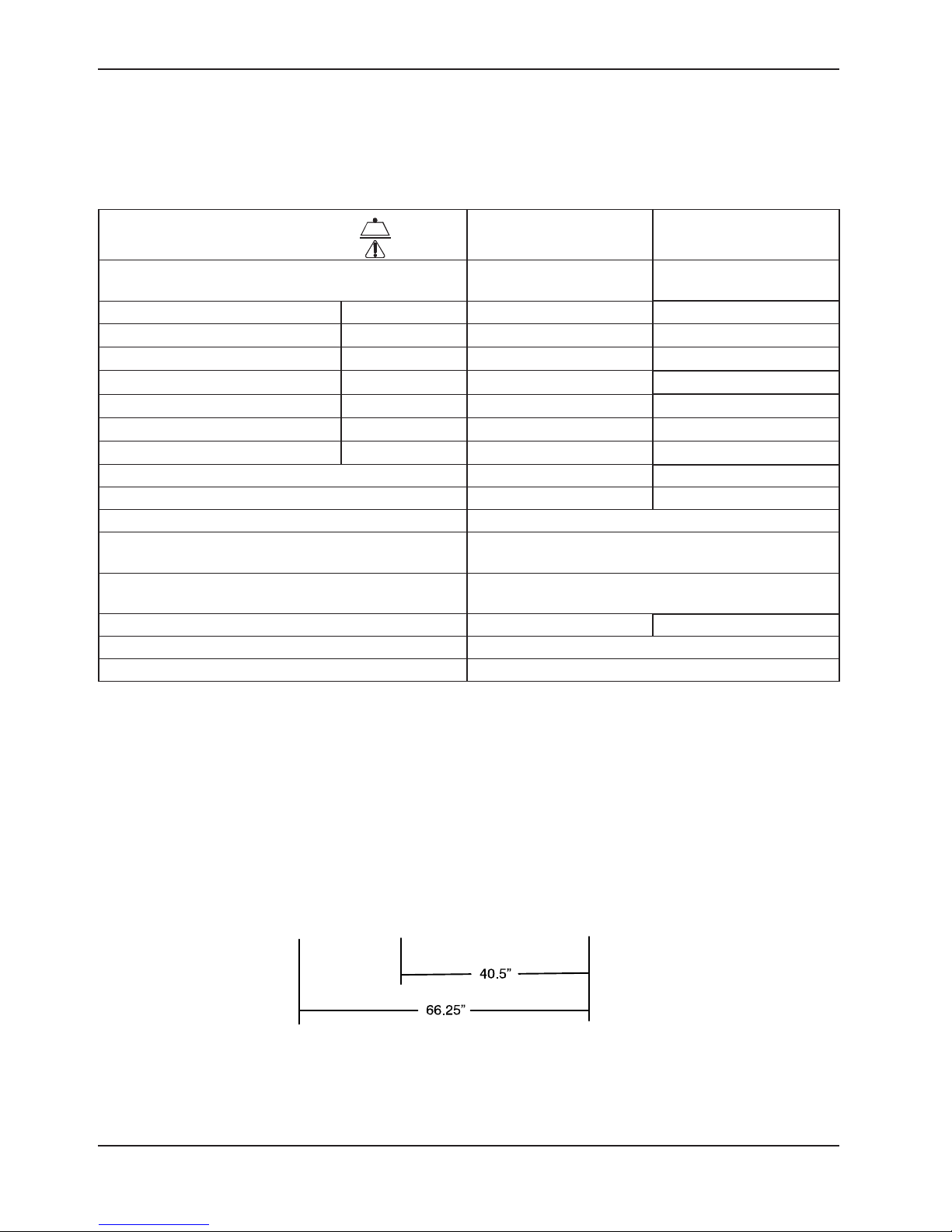
SPECIFICATIONS
Maximum Cot Load Capacity 650 pounds 294,8 kg
Overall Length/Minimum Length/Width 80.5" / 62" / 23" 204,5 cm /
157,5 cm / 58,4 cm
1
Height
See page 19 for positions. Position 2 21.0” 53,3 cm
2
Weight
Caster Diameter/Width 6" / 2" 15,2 cm / 5,1 cm
Backrest Articulation/Shock Position 2° to 73° / +14°
Minimum Operators Required for Loading/
Unloading an Occupied Cot
Recommended Fastener Systems Model 6370/6377/6378 Floor Mount Type
Recommended Floor Height
3
Roll-In Style Yes
Single Wheel Lock / Double Wheel Lock Optional
Position 1 13. 5" 34,3 cm
Position 3 25.5” 64,8 cm
Position 4 29.0” 73,7 cm
Position 5 32.0” 81,3 cm
Position 6 35.0” 88,9 cm
Position 7 37.5 ” 95,3 cm
81 pounds 37,7 kg
2
Model 6371 Wall Mount Type
Up to 32" 81,3 cm
1
Height measured from bottom of mattress at seat section to ground level.
2
Cot is weighed without mattress and restraints.
3
Cot may be loaded from any height and a height limiting kit (p/n 6060-202) is available to limit the load height of the cot.
Stryker reserves the right to change specifications without notice.
The MX-PRO is designed to conform to the Federal Specification the Star-of-Life Ambulance KKK-A-1822-F.
The yellow and black color scheme is a proprietary trademark of Stryker Corporation.
Return To Table of Contents
6 60 82-209-0 01 REV A www.stryker.com
Page 7

Introduction
WARNING / CAUTION / NOTE DEFINITION
The words WARNING, CAUTION and NOTE carry special meanings and should be carefully reviewed.
WARNING
Alerts the reader about a situation which, if not avoided, could result in death or serious injury. It may also describe
potential serious adverse reactions and safety hazards.
CAUTION
Alerts the reader of a potentially hazardous situation which, if not avoided, may result in minor or moderate injury to the
user or patient or damage to the equipment or other property. This includes special care necessary for the safe and
effective use of the device and the care necessary to avoid damage to a device that may occur as a result of use or
misuse.
NOTE
Provides special information to make maintenance easier or important instructions clearer.
www.stryker.com 6082-209 -001 REV A 7
Return To Table of Contents
Page 8

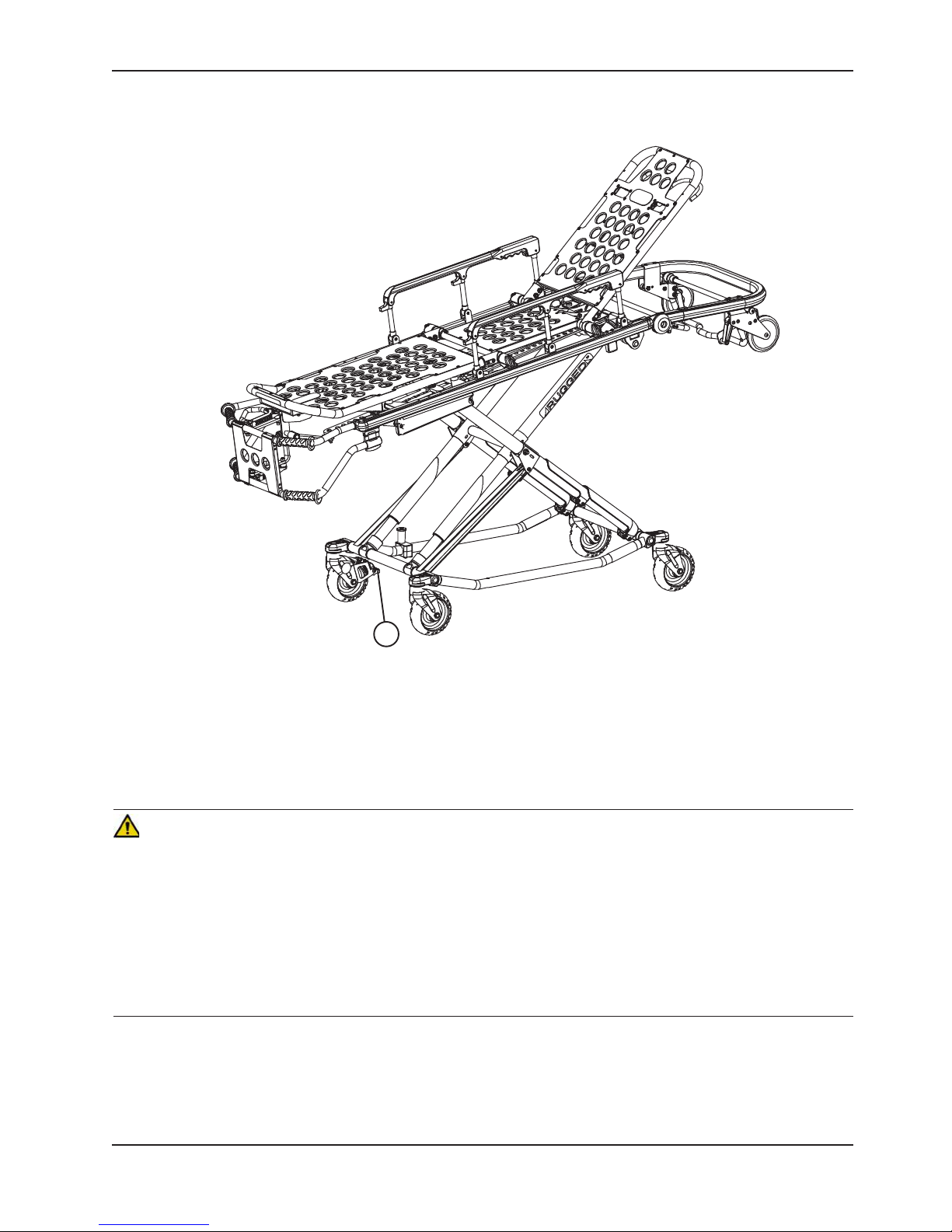
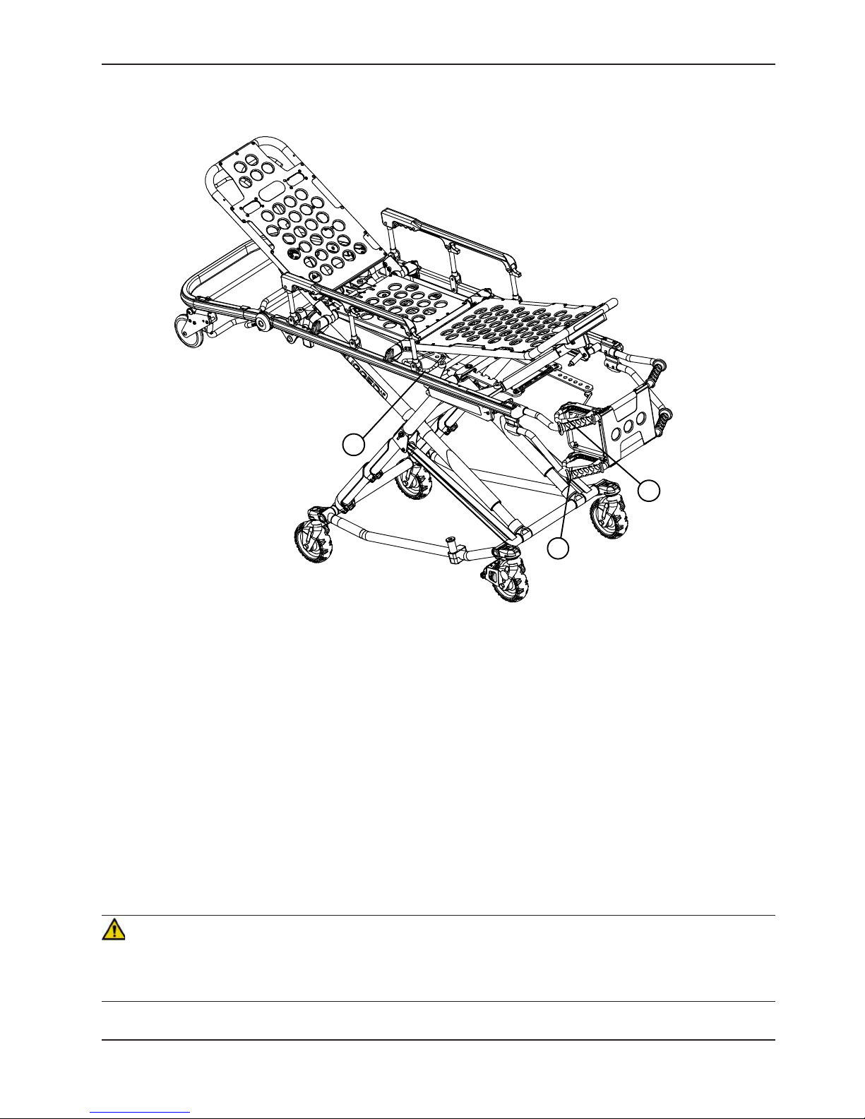
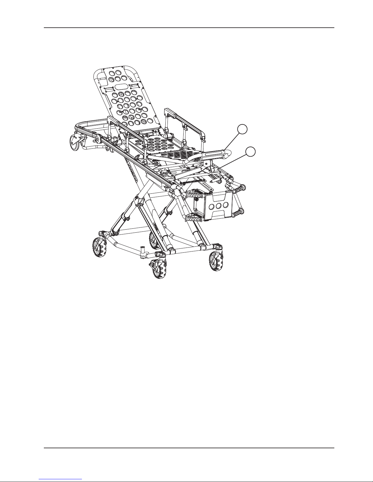
Product Illustration
Height Adjustment
Release Handle
(1 of 3)
Foot Rest
Backrest (Head Section)
Siderail Release Handles
Breakaway
Head Section
Release Bar
Backrest Adjustment
Release Handle
HEAD END
Breakaway
Head Section
Safety Bar
Release
Lever
Loading Wheels
(1 of 2)
Lifting Bar
Return To Table of Contents
8 60 82-209-0 01 REV A www.stryker.com
Foot Rest
Release
Handle
Transport Wheels
J Safety Hook
Stryker part number
6092−036−018
Wheel Lock
(Optional)
Figure 2 − 6082 MX−PRO R3 Cot
Long Safety Hook
Stryker part number
6060−036−018
Transport Wheels
Short Safety Hook
Stryker part number
6060−036−017
Page 9

Symbols and Definitions
Warning, consult accompanying documentation
Safe Working Load Symbol
Manufacturer
www.stryker.com 6082-209 -001 REV A 9
Return To Table of Contents
Page 10

Warranty
Stryker EMS, a division of the Stryker Corporation, offers two distinct warranty options in the United States:
One (1) year parts and labor. Under this option, Stryker EMS warrants to the original purchaser that its products
should be free from manufacturing non-conformances that affect product performance and customer satisfaction for
a period of one (1) year after date of delivery. Stryker’s obligation under this warranty is expressly limited to supplying
replacement parts and labor for, or replacing, at its option, any product that is, in the sole discretion of Stryker, found
to be defective.
Two (2) year parts. Under this option, Stryker EMS warrants to the original purchaser that non-expendable components
of its products should be free from manufacturing non-conformances that affect product performance and
customer satisfaction for a period of two (2) years after date of delivery. Stryker’s obligation under this warranty
as expressly limited to supplying replacement parts for, or replacing, at its option, any product which is, in the sole
discretion of Stryker, found to be defective. Expendable components, i.e. mattresses, restraints, I.V. poles, storage
nets, storage pouches, oxygen straps, and other soft goods, have a one (1) year limited warranty with this option.
Under either warranty option, Stryker EMS products are designed for a 5 year expected service life under normal use,
conditions, and with appropriate periodic maintenance as described in the maintenance manual for each device. Stryker
warrants to the original purchaser that the welds on its EMS products will be free from structural defects for the expected
5 year life of the EMS product as long as the original purchaser owns the product. Original purchasers will also obtain a
three (3) year limited parts warranty for the X-frame components of the MX-PRO R3 stretcher provided they also purchase
X-frame guards at the time of the original purchase and the guards are installed on the MX-PRO before it is put into service.
If Stryker requests, products or parts for which an original purchaser makes a warranty claim, the purchaser shall
return the product or part prepaid freight to Stryker’s factory.
Any improper use or alteration or repair by unauthorized service providers in such a manner as in Stryker’s judgment
affects the product materially and adversely, shall void this warranty. Any repair of Stryker products using parts not
provided or authorized by Stryker shall void this warranty. No employee or representative of Stryker is authorized to
change this warranty in any way.
This statement constitutes Stryker EMS’s entire warranty with respect to the aforesaid equipment. STRYKER MAKES NO
OTHER WARRAN TY OR REPRESENTATION EITHER EX PRESSED OR IMPLIED, EXCEPT AS SET FORTH H EREIN. THERE
IS NO WARRANTY OF MERCHANTABILITY AND THERE ARE NO WARRANTIES OF FITNESS FOR ANY PARTICULAR
PURPOSE. IN NO EVENT SHALL STRYKER BE LIABLE HEREUNDER FOR INCIDENTAL OR CONSEQUENTIAL
DAMAGES ARISING FROM OR IN ANY MANNER RELATED TO SALES OR USE OF ANY SUCH EQUIPMENT.
Return To Table of Contents
10 6082-209 -001 REV A www.stryker.com
Page 11

Warranty
STRYKER EMS RETURN POLICY
Cots, Stair Chairs, Evacuation Chairs, Cot Fasteners and Aftermarket Accessories may be returned up to 180 days of
receipt if they meet the following guidelines:
Prior to 30 Days
• 30daymoneybackguaranteeineffect
• StrykerEMSisresponsibleforallcharges
• Returnswillnotbeapprovedonmodifieditems
Prior to 90 Days
• Productmustbeunused, undamaged and in the original packaging
• Customerisresponsiblefora10%restockingfee
Prior to 180 Days
• Productmustbeunused, undamaged and in the original packaging
• Customerisresponsiblefora25%restockingfee
RETURN AUTHORIZATION
Merchandise cannot be returned without approval from the Stryker Customer Service Department. An authorization
number will be provided which must be printed on the returned merchandise. Stryker reserves the right to charge
shipping and restocking fees on returned items.
SPECIAL, MODIFIED, OR DISCONTINUED ITEMS NOT SUBJECT TO RETURN.
DAMAGED MERCHANDISE
ICC Regulations require that claims for damaged merchandise must be made with the carrier within fifteen (15)
days of receipt of merchandise. DO NOT ACCEPT DAMAGED SHIPMENTS UNLESS SUCH DAMAGE IS NOTED
ON THE DELIVERY RECEIPT AT THE TIME OF RECEIPT. Upon prompt notification, Stryker will file a freight claim
with the appropriate carrier for damages incurred. Claim will be limited in amount to the actual replacement cost. In
the event that this information is not received by Stryker within the fifteen (15) day period following the delivery of
the merchandise, or the damage was not noted on the delivery receipt at the time of receipt, the customer will be
responsible for payment of the original invoice in full.
Claims for any short shipment must be made within thirty (30) days of invoice.
INTERNATIONAL WARRANTY CLAUSE
This warranty reflects U.S. domestic policy. Warranty outside the U.S. may vary by country. Please contact your local
Stryker Medical representative for additional information.
PATENT INFORMATION
The Stryker MX-PRO R3 cot is covered by one or more of the following patents:
United States 5,537,700 5,575,026 6, 908,133 7,100 , 224
Other patents pending
www.stryker.com 6082-209 -001 REV A 11
Return To Table of Contents
Page 12

Summary of Safety Precautions
The following is a list of safety precautions that must be observed when operating or servicing this unit. The precautions
are repeated throughout the manual, where applicable. Carefully read this list before using or servicing the unit.
WARNING
• Improper usage of the cot can cause injury to the patient or operator. Operate the cot only as described in this
manual.
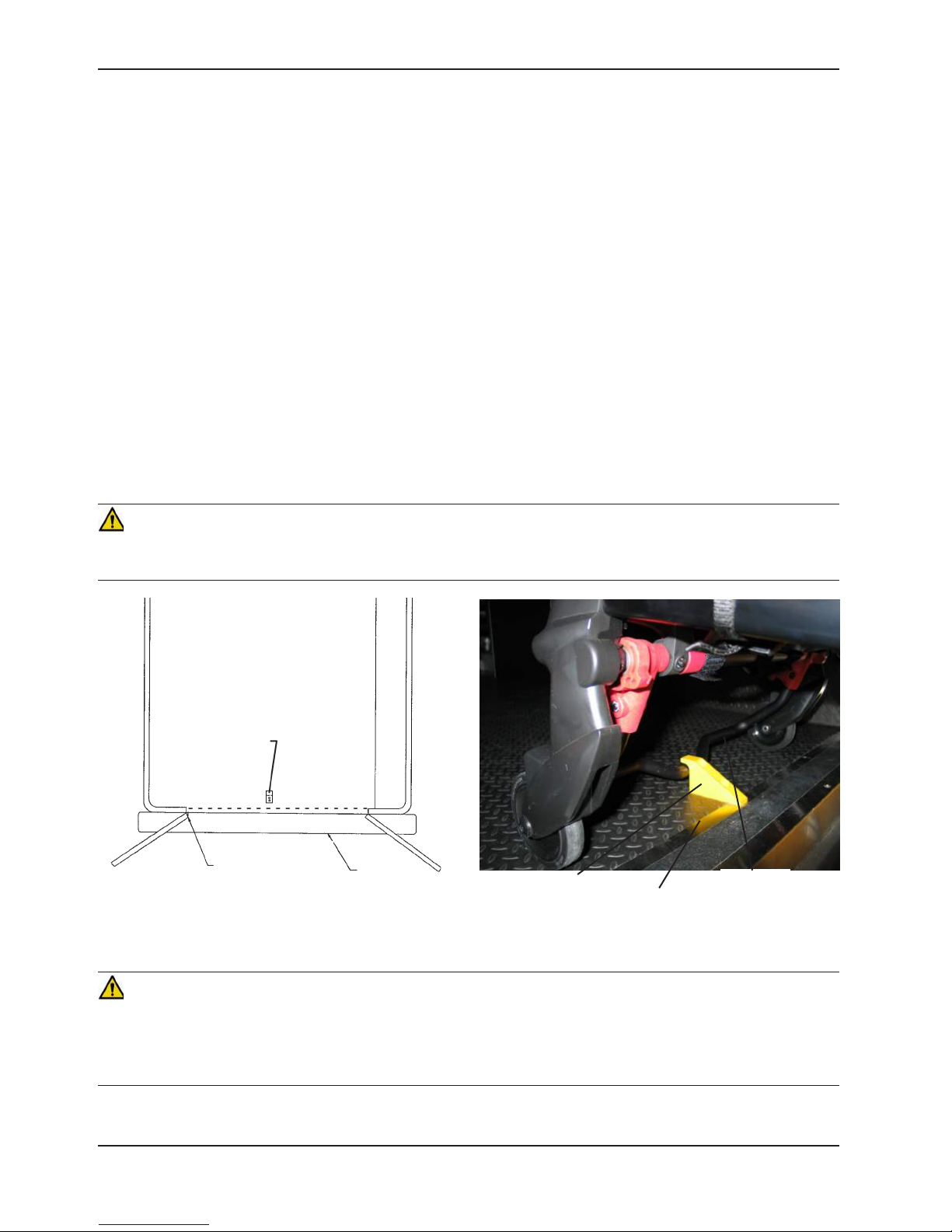
• Install the safety hook at least 1/8 inch from the edge of the rear ambulance door. After installation, verify the cot
legs lock into the load position without contacting the ambulance bumper.
• Have the vehicle safety hook installed by a certified mechanic. Improper safety hook installation can result in
injury to the patient or operator or damage to the unit.
• Failure to install the vehicle safety hook can result in injury to the patient or operator. Install and use the safety
hook as described in this manual.
• To avoid injury, verify the safety bar has engaged the safety hook before removing the cot from the patient
compartment.
• Always use all restraint straps to secure the patient on the cot. An unrestrained patient may fall from the cot and
be injured.
• To avoid accidental release of the Pedi−Mate™, and possible injury to the infant, ensure the buckle is located away
from obstructions on the cot or head end storage pouch.
• Siderails are not intended to serve as a patient restraint device. See page 20 for proper restraint strap usage.
Failure to utilize the siderails properly could result in patient injury.
• Never leave a patient unattended on the cot or injury could result. Hold the cot securely while a patient is on the
cot.
• Never apply the optional wheel lock(s) while a patient is on the cot. Tipping could occur if the cot is moved while
wheel locks are applied, resulting in injury to the patient or operator and/or damage to the cot.
• Wheel locks are only intended to help prevent the cot from rolling while unattended. Wheel locks may not provide
sufficient resistance on all surfaces or under loads.
• Never install or use wheel locks on a cot with excessively worn wheels. Installing or using wheel locks on wheels
with less than a 6” diameter could compromise the holding ability of the wheel lock, resulting in injury to the patient
or operator and/or damage to the cot or other equipment.
• Be sure the undercarriage has engaged and locked before removing the loading wheels from the patient
compartment floor of the vehicle. An unlocked undercarriage will not support the cot and injury to the patient and/
or operator could result.
• Grasping the cot improperly can cause injury. Grasp only the lifting bars to lift the cot. Keep hands, fingers and
feet away from moving parts. To avoid injury, use extreme caution when placing your feet near the base tubes
while raising and lowering the cot.
• Do not pull or lift on the safety bar when unloading the cot. Damage to the safety bar could result and injury to
the patient or operator could occur.
• The one person loading and unloading procedures are for use only with an empty cot. Do not use the procedures
when unloading a patient. Injury to the patient or operator could result.
• The cot must have at least 5/8” of clearance between the ambulance bumper and the cot to disengage the safety
bar when unloading the cot from the ambulance. Verify the cot legs lock into the load position before disengaging
the safety bar from the safety hook. Failure to properly lock the cot into position can cause injury to the patient or
operator and/or damage to the cot.
• Do not allow untrained helpers to assist in the operation of the cot. Untrained technicians/helpers can cause injury
to the patient or themselves.
• When the optional head end storage pouch is being used, ensure it does not interfere with the operation of the
safety bar and safety hook. Injury to the patient or operator could occur.
• Use any appropriate personal safety equipment (goggles, respirator, etc.) to avoid the risk of inhaling contagion.
Use of power washing equipment can aerate contamination collected during the use of the cot.
• Do not ride on the base of the cot. Damage to the cot could occur, resulting in injury to the patient or operator.
• Failure to properly clean or dispose of contaminated mattress or cot components will increase the risk of exposure
to bloodborne pathogens and may cause injury to the patient or the operator.
Return To Table of Contents
12 6082-209 -001 REV A www.stryker.com
Page 13

Summary of Safety Precautions
WARNING (CONTINUED)
• Do not modify the cot. Modifying the cot can cause unpredictable operation resulting in injury to the patient or
operator. Modifying the cot will also void its warranty.
• Operating the cot with the breakaway head section lowered may cause injury to the patient or operator or damage
to the cot. Use only positions 5−7 (see page 19) when using this configuration.
• High obstacles such as curbing, steps or rough terrain can cause the cot to tip, possibly causing injury to the patient
or operator. Transporting the cot in lower positions reduces the potential of a cot tip. If possible, obtain assistance
or take an alternate route.
CAUTION
• Height limit kit is recommended for ambulance deck heights less than 30 inches (76 cm) − Stryker part number
6060−202−000.
• Damage to the cot can occur if the cot is lowered in the shortened position. Use only positions 5−7 (see page
19) when the cot is shortened.
• Do not allow the cot undercarriage to drop unassisted (commonly known as a “hot drop”) when removing the cot
from the vehicle. Repeated hot dropping will cause premature wear or damage to the cot.
• Do not store items under the cot mattress. Storing items under the mattress can interfere with the operation of
the cot.
• The weight of the I.V. bags or equipment must not exceed 40 pounds.
• Improper maintenance can cause injury or damage to the unit. Maintain the cot as described in this manual. Use
only Stryker approved parts and maintenance procedures. Using unapproved parts and procedures could cause
unpredictable operation and/or injury and will void the product warranty.
• The weight of the monitoring equipment must not exceed 75 pounds (34 kg) with the defibrillator platform (if
equipped). Monitoring equipment should not be stored on the cot or on the defibrillator platform when in the
ambulance vehicle.
www.stryker.com 6082-209 -001 REV A 13
Return To Table of Contents
Page 14

Setup Procedures
Unpack the cartons and check all items for proper operation. It is important that the cot is working properly before it
is put into service. Have a qualified service person use the following list and the operation instructions to check the
cot before it is put into service.
Note: Ensure that all shipping and packaging materials have been removed from the product(s) prior to use.
• All fasteners secure (reference all assembly drawings)
• All welds intact, not cracked or broken
• No bent or broken tubing or sheet metal
• No debris in wheels
• All wheels secure, rolling and swivelling properly
• Siderails move and latch properly
• Backrest operating properly
• Optional accessories intact and operating properly
• Height positioning latch functioning properly
• Cot secure in each height position
• Undercarriage folds properly
• Breakaway head section operating properly
• Safety bar operating properly
• Foot rest operating properly
• No rips or cracks in mattress cover
• Body restraints intact and working properly
• Wheel lock(s) operating properly (optional equipment)
• Does the vehicle safety hook engage the safety bar so that the cot loads and unloads easily from the vehicle?
• Is there an approved crash−stable fastener (Stryker part number 6370/6377/6378 or 6371 − not included) installed
in the vehicle?
The patient compartment of the vehicle in which the Cot will be used must have:
• A smooth rear edge for cot loading.
• A level floor large enough for the folded cot.
• Stryker 6370/6377/6378/6379 or 6371 crash stable cot fastener (not included).
• 32” (81 cm.) maximum loading height.
• Space to install the safety hook.
When necessary, modify the vehicle to fit the cot. Do not modify the cot.
WARNING
Do not modify the cot. Modifying the cot can cause unpredictable operation resulting in injury to the patient or operator.
Modifying the cot will also void its warranty (see page 10).
Return To Table of Contents
14 6082-20 9-001 REV A www.stryker.com
Page 15
Vehicle Safety Hook Selection
The vehicle safety hook is a device that ships with the cot. The cot safety bar and vehicle safety hook are designed
to keep the cot from being accidentally removed from the vehicle and to provide increased operator assurance and
confidence when loading and unloading. The safety hook was designed for compatibility and proper operation when
loading and unloading the cot from a vehicle that is compliant with Federal Regulation KKK-A-1822.
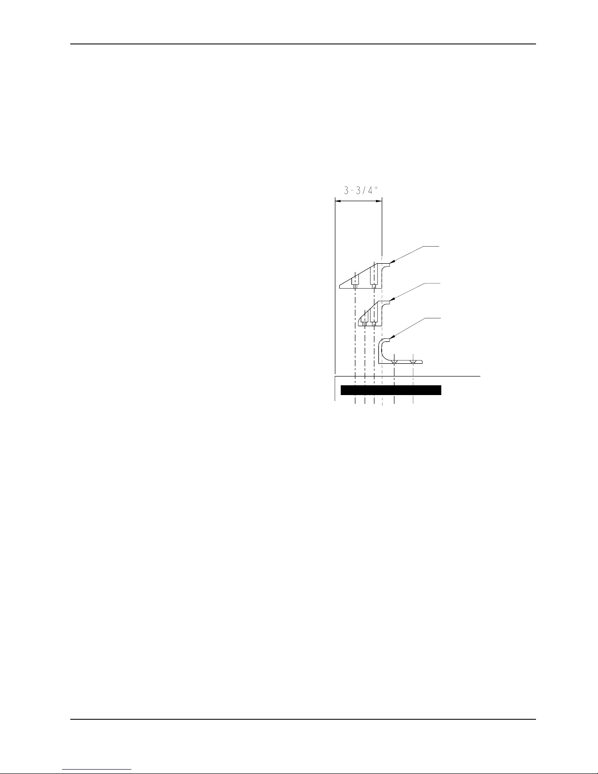
Stryker offers three different types of safety hooks that are ordered and shipped with your ambulance cot. These
safety hook types are designed to meet the needs of various emergency vehicle configurations, specifically the length
and location of the floor structure support that is located in the rear of the vehicle.
Consider the following information when selecting
which safety hook is appropriate for your vehicle
configuration:
• Determine the location of the floor structure
support where there is adequate room to mount
the safety hook.
• Ensure that the safety hook can be securely
mounted into the back of the vehicle while
providing adequate bumper clearance to allow the
cot to be loaded and unloaded from the vehicle.
• Note the differences in vehicle design. Each safety
hook provides a different mounting location option
to maintain the appropriate distance between the
face of the safety hook and the edge of the door
sill.
Long Safety Hook
6060-036-018
Short Safety Hook
6060-036-017
J-Style Safety Hook
6092-036-018
Due to the differences in vehicle dimensions and the
floor structure support locations, each safety hook
requires a different mounting location. See “Vehicle
Safety Hook Installation” to determine the correct
positioning for safety hook installation.
Safety Hook Types
Note: When replacing an existing safety hook with a new style, adjust the mounting location to maintain the proper
position of the safety hook face.
www.stryker.com 6082-209 -001 REV A 15
Return To Table of Contents
Page 16
Vehicle Safety Hook Installation
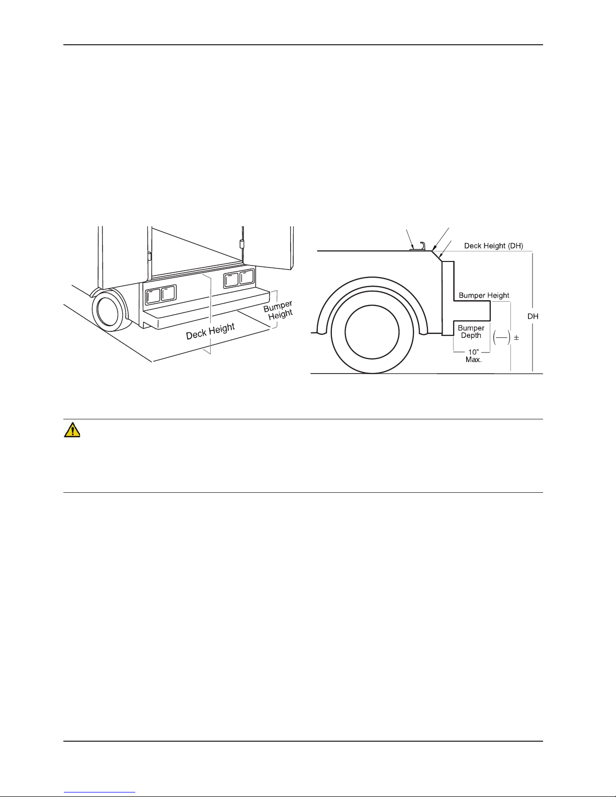
VEHICLE CONFIGURATION
According to federal regulations (reference KKK-A-1822), the bumper height of the vehicle shall be installed equidistant
± 5 cm (2 inches) from the vehicle floor to the ground level, which is defined as the vehicle deck height. The bumper
step shall have a minimum depth of 13 cm (5 inches) and a maximum depth of 25 cm (10 inches). If the bumper depth
is greater than 18 cm (7 inches), then the bumper must be able to fold. Installation of the safety hook into any vehicle
compliant with this federal specification provides adequate clearance for the cot base to lower to its fully extended
position. The cot is compatible with all vehicle deck heights (see specifications for maximum load height) as long as
the vehicle meets the federal specifications that are outlined in KKK-A-1822.
Sill Edge
Sill
DH
2
2
Vehicle Deck Height
Safety Hook
Vehicle Deck Height
CAUTION
• Set the cot load height to the proper stop height prior to operation.
• Installation of the safety hook should be done by a certified mechanic familiar with ambulance vehicle construction.
Consult the vehicle manufacturer before installing the safety hook and be sure that the installation of the safety hook
does not damage or interfere with the brake lines, oxygen lines, fuel lines, fuel tank or electrical wiring of the vehicle.
REQUIRED HARDWARE FOR INSTALLATION OF THE SAFETY HOOK (NOT SUPPLIED)
(2) Grade 5, 1/4”-20 Socket Head Cap Screws*
(2) Grade 5, 1/4”-20 Flat Socket Head Cap Screws*
(2) Flat Washers
(2) Lock Washers
(2) 1/4”-20 Nuts
* The length of the socket head cap screws depends on the thickness of the vehicle floor. Use screws that are long
enough to go completely through the patient compartment floor, washer and nut by at least two full threads.
Return To Table of Contents
16 608 2-209 -001 REV A w ww.stryker.com
Page 17
Vehicle Safety Hook Installation
WARNING
• Have the vehicle safety hook installed by a certified mechanic. Improper safety hook installation can cause injury
to the patient or operator and/or damage to the cot.
• Failure to install the safety hook can cause injury to the patient or operator.
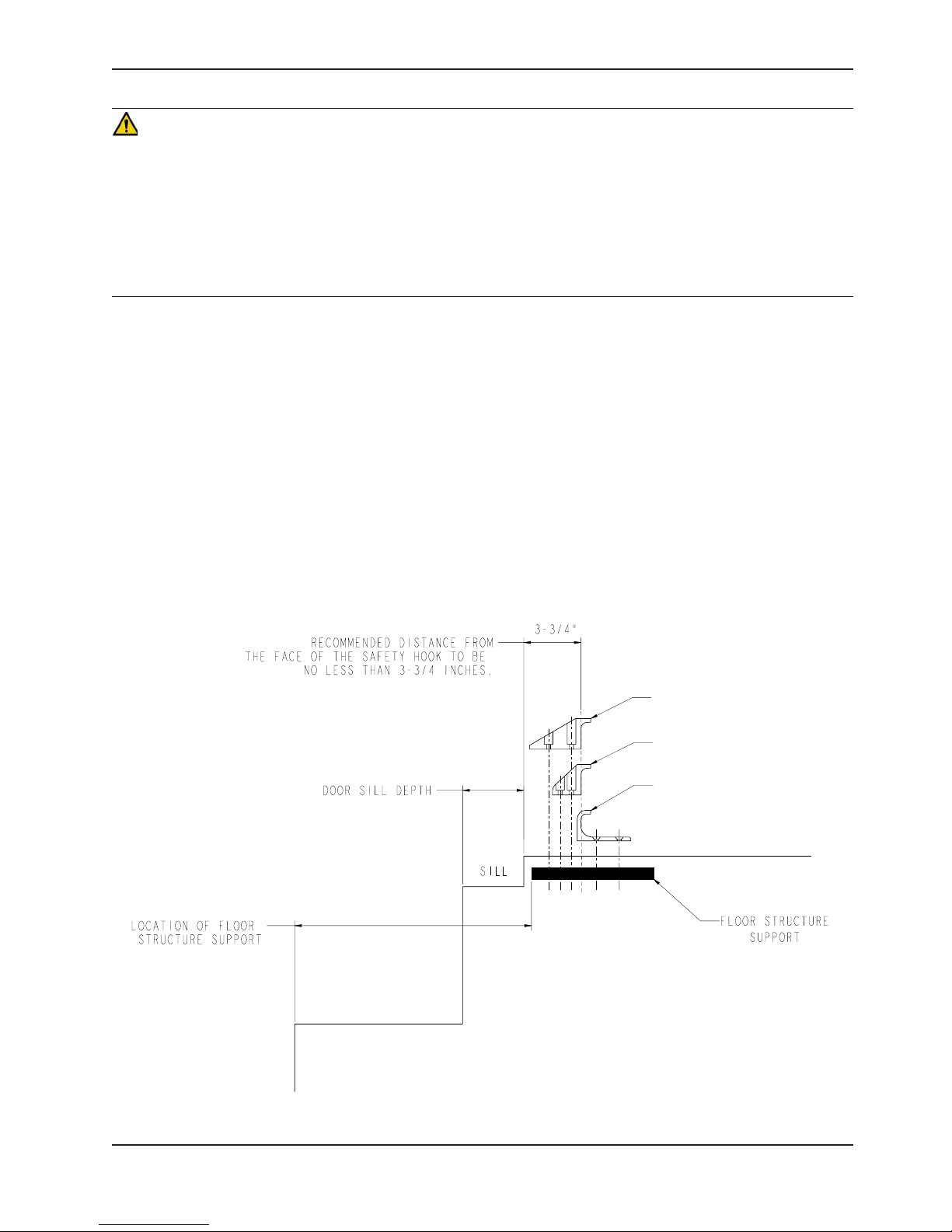
• The face of the safety hook that engages the safety bar should be located at least 3-3/4” from the leading edge
of the door sill. After installation, verify that the cot legs lock into the load position without contacting the vehicle
bumper.
• To avoid injury, verify that the safety bar has engaged the safety hook before removing the cot from the patient
compartment.
Note: Stryker recommends that, prior to installation, the certified mechanic plan the placement of the safety hook in
the rear of the vehicle.
Before installing the safety hook into your vehicle, check the front to back and side to side positioning when unloading
and loading the cot to ensure that the safety hook will be installed properly. The cot safety bar must engage the safety
hook every time, regardless of cot position.
FRONT TO BACK POSITIONING OF THE SAFETY HOOK
1. Select the appropriate safety hook for your vehicle configuration.
2. Position the safety hook at least 3-3/4” from the leading edge of the door sill.
3. Ensure that the safety hook can be securely mounted into the back of the vehicle while providing adequate bumper
clearance to allow the cot to be loaded and unloaded from the vehicle.
4. See “Side to Side Positioning of the Safety Hook” to confirm the side to side placement.
Long Safety Hook
6060-036-018
Short Safety Hook
6060-036-017
J-Style Safety Hook
6092-036-018
Safety Hook Placement
Return To Table of Contents
www.stryker.com 6082-209 -001 REV A 17
Page 18
Vehicle Safety Hook Installation
SIDE TO SIDE POSITIONING OF THE SAFETY HOOK
1. Remove the cot from the fastener and unload it from the vehicle.
2. While the cot is being removed, note the position of the load wheels and the safety bar.
3. Mark the center of the cot safety bar on the vehicle floor.
4. Verify that the position marked in Step 3 is where the safety bar engages the safety hook every time when
unloading the cot in a variety of positions (all the way to the left and all the way to the right), regardless of cot
position.
• If the cot safety bar does not engage the safety hook in any of these positions (left, center, or right), modify
the vehicle, not the cot or safety hook.
• If the cot safety bar engages the safety hook every time, install the safety hook.
INSTALLING THE SAFETY HOOK
1. Determine the correct safety hook front to back and side to side positioning, so the cot safety bar engages the
safety hook every time.
2. Drill the holes for the socket head cap screws.
3. Fasten the safety hook to the patient compartment floor and verify that the safety hook always engages the cot
safety bar regardless of how the cot is unloaded from the vehicle.
WARNING
Verify that the safety hook always engages the cot safety bar regardless of how the cot is unloaded from the vehicle or
injury to the patient or operator and/or damage to the cot may occur.
Top View of Vehicle
Bumper
Squad Bench
Safety Hook
Floor Edge
Safety Bar Engaging Safety Hook
Safety Bar
Safety Hook
Door Frame
Safety Hook Placement
(For Reference Only)
WARNING
The cot must have at least 5/8” of clearance between the vehicle bumper and the cot to disengage the safety bar when
unloading the cot from the vehicle. Verify that the cot legs lock into the load position before disengaging the safety bar
from the safety hook. Failure to properly lock the cot into position can cause injury to the patient or operator and/or
damage to the cot.
Return To Table of Contents
18 608 2-209 -001 REV A w ww.stryker.com
Page 19
Cot Positions
Position 1 - Use for patient transfer.
Position 2 - Use for patient transfer/cot rolling.
Position 6 - Use for patient transfer/cot rolling.
Position 3 - Use for patient transfer/cot rolling.
Position 4 - Use for patient transfer/cot rolling.
Position 5 - Use for patient transfer/cot rolling.
Position 7 - Use for patient transfer/cot rolling.
WARNING - Operating the cot with the breakaway
head section lowered may cause injury to the
patient or operator or damage to the cot. Use only
positions 5-7 when using this configuration.
www.stryker.com 6082-209 -001 REV A 19
Return To Table of Contents
Page 20
Cot Operations
USING PATIENT RESTRAINT STRAPS
WARNING
Always use all restraint straps to secure the patient on the cot. An
unrestrained patient may fall from the cot and be injured.
Figure 6 - Safety Restraints
Always secure the patient on the cot with all the restraint straps. Buckle
the restraints across the patient’s chest/shoulders, waist and legs as
shown in Figure 6. Keep the restraint straps buckled when the cot is not
being used with a patient to avoid damage to the buckles and straps.
When attaching the restraint straps to the cot, keep in mind the
attachment points should provide strong anchorage and proper restraint
position while not interfering with equipment and accessories. Wrap
the strap around the cot frame and back through the loop on the end
of the strap as shown in Figures 7 and 8. The arrows indicate alternate
attachment areas.
Figure 7 - Back Rest Restraints
Return To Table of Contents
20 6082-209 -001 REV A www.stryker.com
Figure 8 - Foot Section Restraints
Page 21
Cot Operations
USING PATIENT RESTRAINT STRAPS (CONTINUED)
When the cot is put into service, the restraints are
opened and placed to either side of the cot until
the patient is positioned on the cot mattress. The
restraint is lengthened, buckled around the patient
and shortened until the required tightness is achieved.
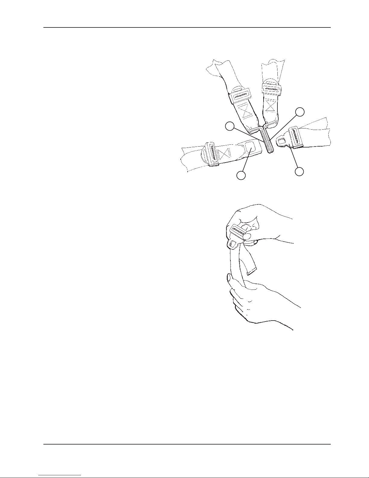
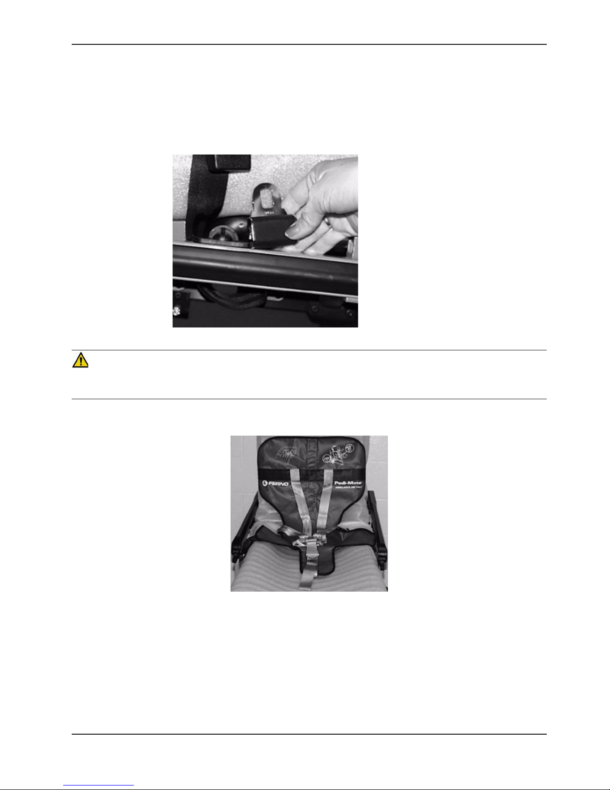
To Open the Safety Restraint:
• Press the red button (A) on the front of the buckle
”receiver”. This releases the buckle tang” (B)
which can then be pulled out of the receiver as
shown in Figure 9.
To Close the Safety Restraint:
• Push the tang into the receiver until a ”click” is
heard. When fastening the chest restraint, be
sure the tang passes through both links (C) on
the shoulder strap as shown in Figure 9.
To Lengthen the Safety Restraint:
• Grasp the buckle tang, turn it at an angle to the
webbing, then pull it out as shown in Figure 10. A
hemmed tab at the end of the webbing prevents
the tang from coming off the strap.
To Shorten the Safety Restraint:
• Grasp the hemmed tab and pull the webbing back
through the tang until the required tightness is
achieved as shown in Figure 11.
Note:
• Whenever a restraint is buckled on a patient, the
attendant should check to be sure the tang is
fully engaged and that the extra webbing is not
tangled in the cot or hanging loose.
• Inspection of the restraints should be done at
least once a month (more frequently if used
heavily). Inspection should include checking for
a bent or broken receiver or tang, torn or frayed
webbing, etc. Any restraint showing wear or not
operating properly must be replaced immediately.
C
C
A
B
Figure 9 - Buckling the Safety Restraints
Figure 10 - Lengthening the Safety Restraint
www.stryker.com 6082-209 -001 REV A 21
Figure 11 -
Shortening the Safety
Restraint
Return To Table of Contents
Page 22

Cot Operations
PEDI-MATE® INFANT RESTRAINT SYSTEM ATTACHMENT INSTRUCTIONS (OPTIONAL EQUIPMENT)
Refer to the Pedi-Mate® users manual for the manufacturer’s recommendations for the use, operation and care of the
Pedi-Mate® Infant Restraint System.
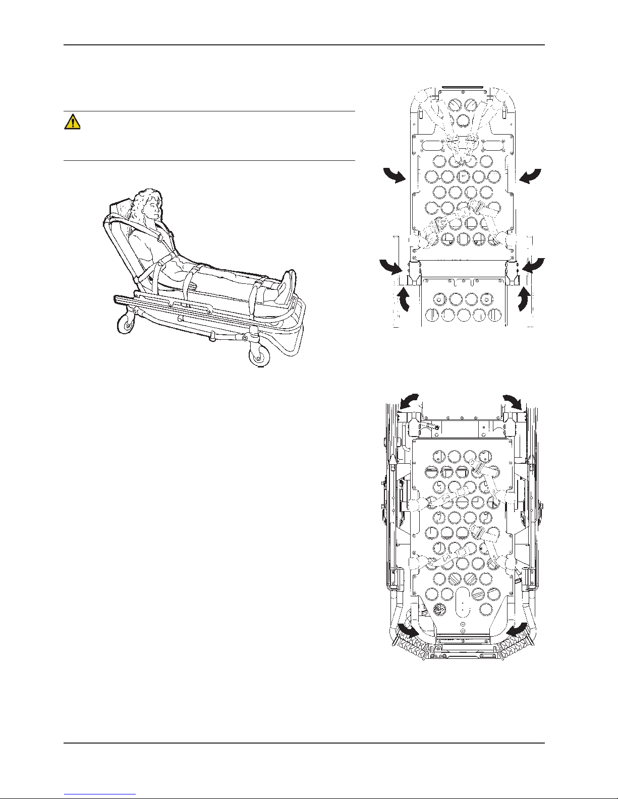
Securing the Pedi-Mate® to the cot:
1. Remove any restraints already attached to the cot.
2. Raise the cot backrest to the full upright position.
3. Position the Pedi-Mate® pad flat on the backrest with the black backrest straps out (see Figure 12).
Figure 12 - Positioning the Pedi-Mate®
4. Wrap the straps around the backrest and insert the ends of the straps through the brackets. Securely fasten the
buckle (see Figure 13).
Figure 13 - Fastening the Pedi-Mate® Buckle
WARNING
To avoid accidental release of the Pedi-Mate®, and possible injury to the infant, ensure the buckle is located away from
obstructions on the cot or head end storage pouch.
Return To Table of Contents
22 6082-209 -001 REV A www.stryker.com
Page 23
Cot Operations
PEDI-MATE® INFANT RESTRAINT SYSTEM ATTACHMENT INSTRUCTIONS (CONTINUED)
5. Pull firmly on the end of the adjustable backrest strap and tighten it securely.
6. Insert the mainframe straps between the cot frame and the mattress. To ensure the release button is toward
the foot end of the cot, insert the buckle behind the litter crossbrace and bring it up in front of the crossbrace.
Secure the buckle around the crossbrace, leaving a little slack in the strap for final adjustment (see Figure 14).
Figure 14 - Securing the Safety Restraints on a Cot
WARNING
To avoid accidental release of the Pedi-Mate®, and possible injury to the infant, ensure the buckle is located away from
obstructions on the cot.
7. Verify all the straps are snug and fastened securely (see Figure 15).
Figure 15- Pedi-Mate® Strapped to a Cot
Note:
• These are general instructions for installation of the Pedi-Mate®. Safe and proper use of the Pedi-Mate® is solely
at the discretion of the user. Stryker recommends all users be trained on the proper use of the Pedi-Mate® before
using it in an actual situation.
• Retain these instructions for future reference. Include them with the product in the event of transfer to new users.
• Pedi-Mate® is a trademark of Ferno-Washington Inc.
www.stryker.com 6082-209 -001 REV A 23
Return To Table of Contents
Page 24

Cot Operations
OPERATING GUIDELINES
• Use the cot only as described in this manual.
• Read all labels and instructions on the cot before using the cot.
• Use a minimum of two operators to manipulate the cot while a patient is on the cot.
• Do not adjust, roll or load the cot without advising the patient. Stay with the patient and control the cot at all times.
• Never apply the optional wheel lock while a patient is on the cot.
• Always use the restraint straps and keep the siderails up when a patient is on the cot.
• Use properly trained helpers when necessary to control the cot and patient.
TRANSFERRING THE PATIENT TO THE COT
1 Roll the cot to the patient.
2 Place the cot beside the patient and raise/lower the cot to the patient’s level.
3 Lower the siderails and open the restraint straps.
4 Transfer the patient to the cot using accepted EMS procedures.
5 Use all the restraints to secure the patient to the cot (see page 20 for restraint strap usage instructions).
6 Raise the siderails and adjust the backrest and leg rest as necessary.
WARNING
• Always use all restraint straps to secure the patient on the cot. An unrestrained patient may fall from the cot and
be injured.
• Never apply the optional wheel lock while a patient is on the cot. Tipping could occur if the cot is moved while the
wheel lock is applied, resulting in injury to the patient or operator and/or damage to the cot.
ROLLING THE COT
1. Make sure all the restraint straps are securely buckled around the patient (see page 20 for restraint strap usage
instructions).
2. Place the cot in positions 2−7 for rolling (see page 19 for cot positions).
3. When rolling the cot, position an operator at the foot end and one at the head end at all times.
Note:
• Loose items or debris on the patient compartment floor can interfere with the operation of the safety hook and cot
fastener. Keep the patient compartment floor clear.
• The cot can be loaded with the siderails down only if the restraint belts are properly buckled around the patient.
WARNING
Operating the cot with the breakaway head section lowered may cause injury to the patient or operator or damage to the
cot. Use only positions 5−7 (see page 19) when using this configuration.
RAISING/LOWERING THE COT
1. Both users must lift weight up off the base.
2. The user at the foot end must pull the release handle.
3. Both users must lower the cot to the ground or raise the cot up.
Return To Table of Contents
24 6082-209 -001 REV A www.stryker.com
Page 25
Cot Operations
LOADING THE COT INTO A VEHICLE WITH TWO OPERATORS
When loading the cot into a vehicle, an operator should
remember the following important issues:
• Two operators must be present when the cot is occupied.
• There must be a safety hook properly installed in the
vehicle so that the bumper does not interfere with the front
legs of the base frame. (See for safety hook installation
instructions.)
• Operators must be able to lift the total weight of the
patient, cot and any items on the cot.
• The higher an operator must lift the cot, the more difficult
it becomes to hold the weight. An operator may need help
loading the cot if he/she is too short or if the patient is too
heavy to lift safely. The operator must be able to lift the
cot high enough for the cot’s legs to unfold completely and
lock when the cot is unloaded. A shorter operator will have
to raise his/her arms higher to enable the undercarriage
to unfold.
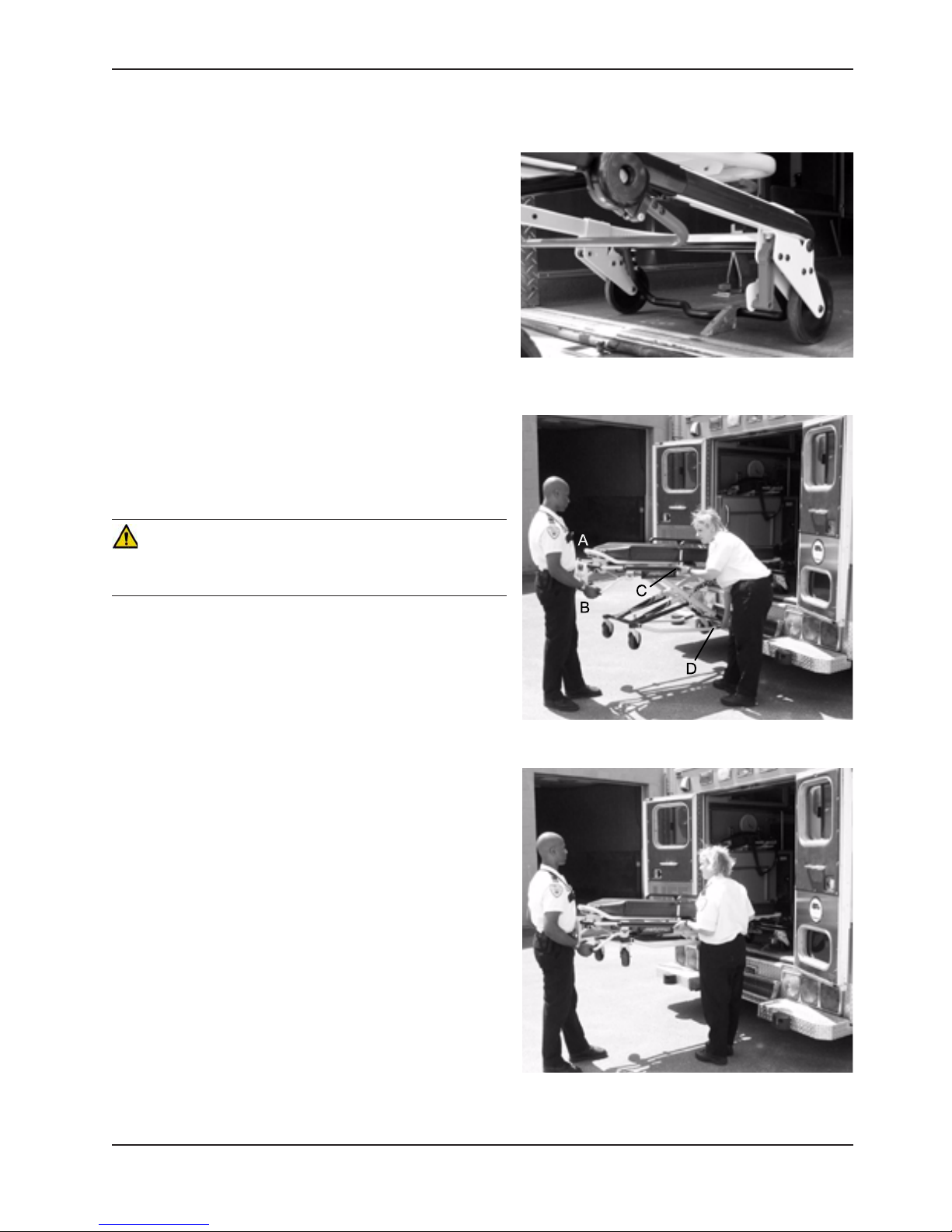
Figure 16 - Safety Bar Engaging Safety Hook
WARNING
Failure to use the safety hook can result in injury. Install and use
the hook as described in this manual.
1. Place the cot in a loading position (any position where
the loading wheels meet the vehicle floor height). Roll the
cot to the open door of the patient compartment. Lift the
vehicle bumper to the raised position (if possible).
2. Push the cot forward until the loading wheels are on the
patient compartment floor and the safety bar passes the
safety hook as shown in Figure 16.
3. For maximum clearance to lift the base, pull the cot back
until the safety bar engages the safety hook. Operator two
should verify that the bar engages the safety hook.
4. Operator 1 − Grasp the cot frame at the foot end. Lift
the foot end of the cot until the weight is off the latching
mechanism. Squeeze and hold the release handle
(location A or B).
5. Operator 2 − Stabilize the cot by placing your hand on
the outer rail (location C). Grasp the base frame where
indicated (location D). After the foot end operator has
lifted the cot and squeezed the release handle, raise the
undercarriage until it stops in the uppermost position and
hold it there (Figure 17).
6. Both Operators − Push the cot into the patient compartment
(Figure 18), engaging the cot fastener (not included).
Figure 17 - 2 Operators - One Lifting the Base
www.stryker.com 6082-209 -001 REV A 25
Figure 18 - 2 Operators - Base Full Up
Return To Table of Contents
Page 26
Cot Operations
LOADING AN EMPTY COT INTO A VEHICLE WITH ONE OPERATOR
WARNING
This procedure is for use only with an empty cot. Do not use
this procedure when loading a patient. Injury to the patient and/
or operator could result.
1. Place the cot in a loading position (any position in which
the load wheels meet the vehicle floor height – see page
19).
2. Roll the cot to the open door of the patient compartment.
3. Lift the vehicle bumper to the raised position (if possible).
4. Push the cot forward until the loading wheels are on the
compartment floor and the safety bar passes the safety
hook.
5. Pull the cot back until the safety bar engages the safety
hook.
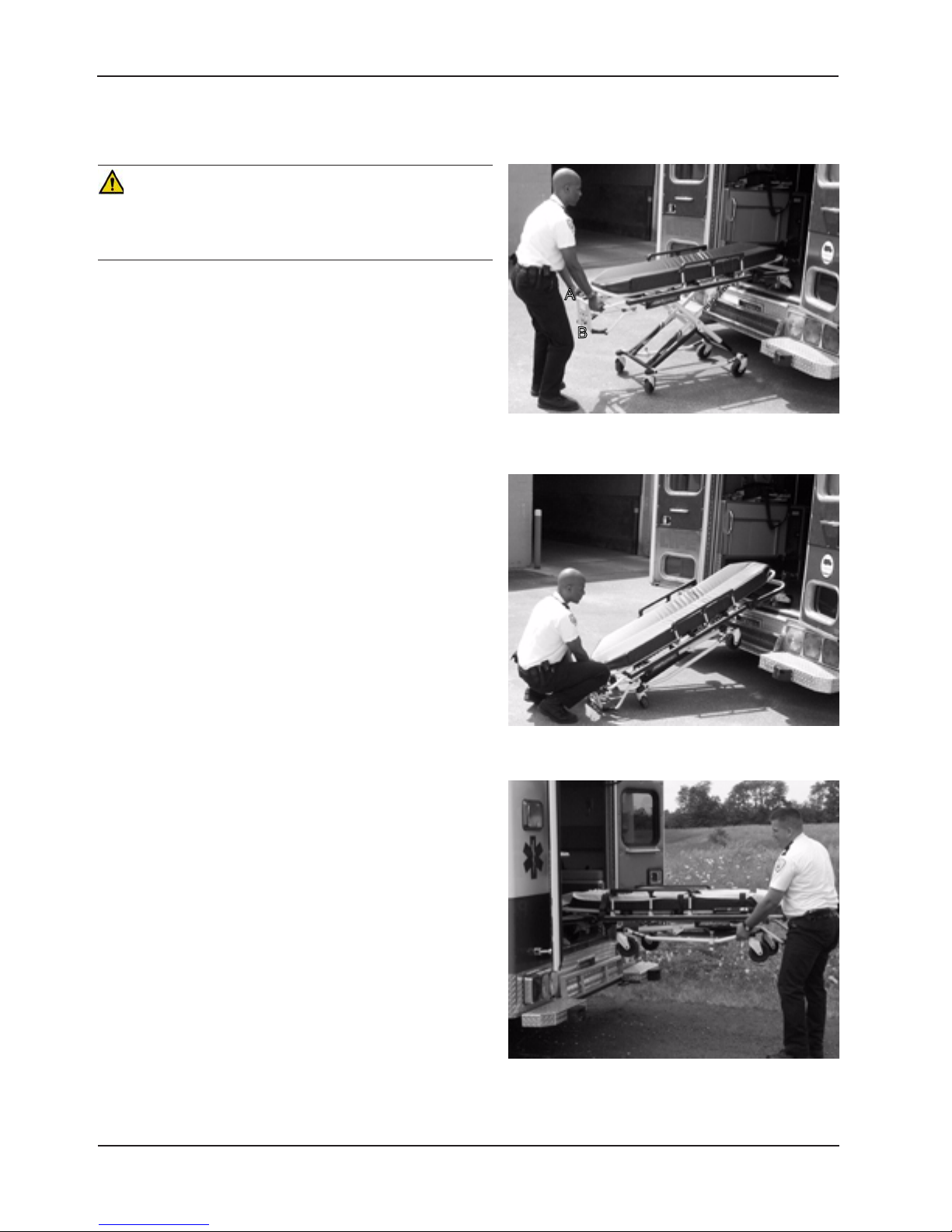
6. Grasp the cot frame at the foot end and squeeze and hold
the release handle (A or B) (Figure 19).
7. Lower the foot end of the cot to the ground, making sure
the cot locks in position 1 (Figure 20).
8. Lift the foot end of the cot until it is level with the
compartment floor.
9. Grasp the base of the cot with one hand and pull up the
base of the cot towards the litter, reducing the space
between the base and the litter (Figure 21).
10. Push the cot into the patient compartment, guiding it into
the cot fastener.
Figure 19 - Squeeze the Release Handle
Figure 20 - Lower the Foot End of the Cot
Figure 21 - Pull Up the Base of the Cot
Return To Table of Contents
26 6082-209 -001 REV A w ww.stryker.com
Page 27

Cot Operations
UNLOADING THE COT FROM A VEHICLE WITH TWO OPERATORS
WARNING
Failure to use the safety hook can cause injury to the patient or operator. Install and use the safety hook as described
in this manual. To avoid injury, verify the safety bar has engaged the safety hook before removing the cot from the patient
compartment.
1. Disengage the cot from the cot fastener. (For more detailed instructions, reference the Cot Fastener Operations
Manual − Model 6370).
2. Operator 1 − Grasp the cot frame. Pull the cot out of the patient compartment until the safety bar engages the
safety hook.
3. Operator 2 − Grasp the base frame where indicated, lift slightly, and lower the base frame to its fully extended
position while operator 1 squeezes and holds the release handle.
4. Operator 1 − Let go of the release handle and be sure the undercarriage locks into place.
5. Operator 2 − Disengage the safety bar from the safety hook by pushing the safety bar release lever forward.
6. Remove the cot loading wheels from the vehicle. Place the cot in a rolling position (cot positions 2−7 − see page
19).
CAUTION
Do not allow the cot undercarriage to drop unassisted (commonly known as a “hot drop”) when removing the cot from
the vehicle. Repeated hot dropping will cause premature wear or damage to the cot.
WARNING
Be sure the undercarriage has engaged before removing the loading wheels from the patient compartment floor of the
vehicle. An unlocked undercarriage will not support the cot and injury to the patient or operator could result.
UNLOADING AN EMPTY COT FROM A VEHICLE WITH ONE OPERATOR
WARNING
This procedure is for use only with an empty cot. Do not use this procedure when unloading a patient. Injury to the
patient and/or operator could result.
1. Lift the vehicle bumper to the raised position (if possible).
2. Grasp the cot frame at the foot end; pull the cot from the vehicle until the safety bar engages the safety hook.
3. Lower the foot end of the cot to the ground (see Figure 20 on page 26).
4. Squeeze and hold the release handle (A or B − see Figure 21 on page 26) and raise the foot end of the cot
back to a level position with the compartment floor.
5. Disengage the safety bar from the safety hook by pushing the safety bar release lever forward and roll the cot out
of the vehicle.
www.stryker.com 6082-209 -001 REV A 27
Return To Table of Contents
Page 28
Cot Operations
USING ADDITIONAL ASSISTANCE
IF EQUIPPED WITH THE RIGHT HAND RELEASE OPTION
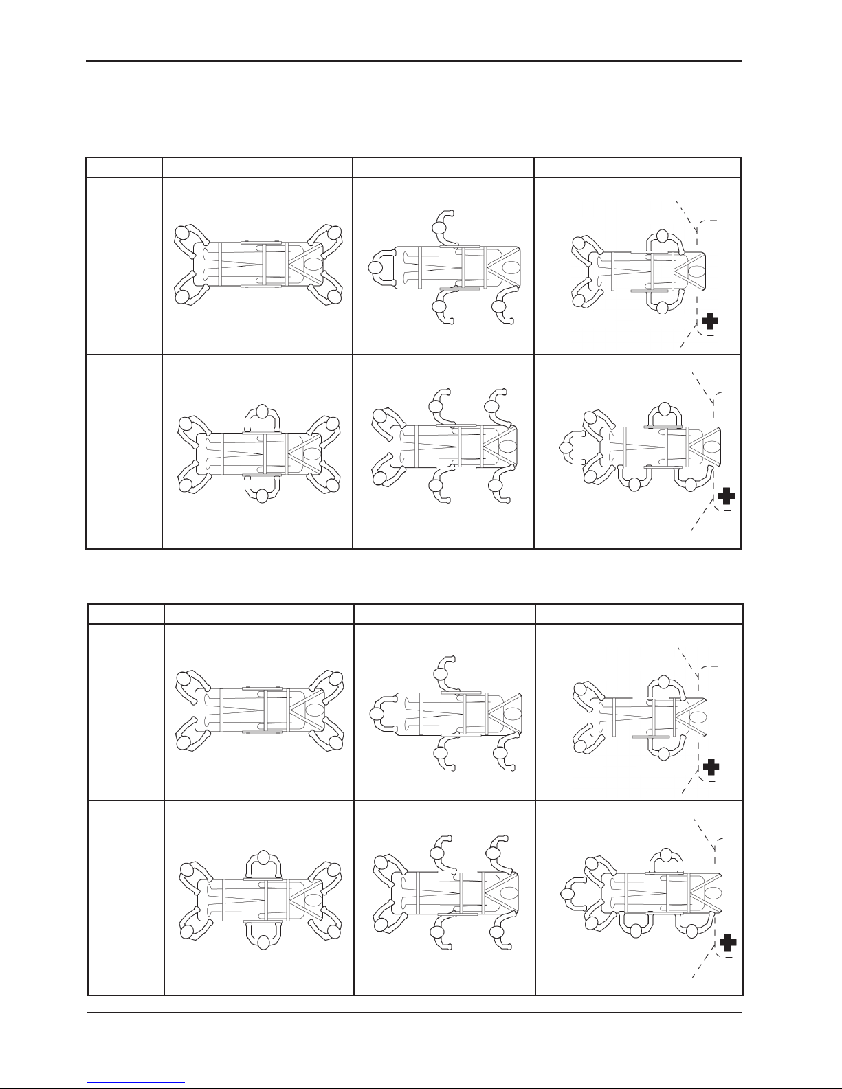
Changing Levels Rolling Loading/Unloading
Helper
Helper
Helper Helper
Helper
Two
Operators
Two
Helpers
Two
Operators
Four
Helpers
Helper
Operator
Helper
Operator
Helper
Helper
Operator
Helper
Operator
Helper
Operator
Helper
Operator
IF EQUIPPED WITH THE LEFT HAND RELEASE OPTION
Operator
Operator
Helper
Operator
Helper
Helper
Operator
Helper
Operator
Helper
Helper
Operator
Changing Levels Rolling Loading/Unloading
Operator
Two
Operators
Two
Helpers
Helper
Operator
Two
Operators
Four
Helpers
Helper
Return To Table of Contents
28 6082-209 -001 REV A w ww.stryker.com
Helper
Helper
Operator
Helper
Operator
Helper
Operator
Operator
Helper
Helper
Helper
Helper Helper
Helper
Operator
Operator
Operator
Helper
Operator
Helper
Helper
Helper
Operator
Helper
Helper
Operator
Page 29
Cot Operations
OPERATING THE OPTIONAL WHEEL LOCK(S)
A
Figure 22 - Wheel Lock
1. To activate the optional wheel lock(s), press down fully on the pedal (A) until it stops.
2. To release the optional wheel lock(s), depress the upper face of the pedal with your foot or lift up with your toe
under the pedal. The upper portion of the pedal will rest against the caster frame when the wheel lock is released.
WARNING
• Never apply the optional wheel lock(s) while a patient is on the cot. Tipping could occur if the cot is moved while
a wheel lock is applied, resulting in injury to the patient or operator and/or damage to the cot.
• Wheel lock(s) are only intended to help prevent the cot from rolling while unattended. A wheel lock may not
provide sufficient resistance on all surfaces or under loads.
• Never leave a patient unattended on the cot or injury could result. Hold the cot securely while a patient is on the
cot.
• Never install or use a wheel lock on a cot with excessively worn wheels. Installing or using a wheel lock on a wheel
with less than a 6” diameter could compromise the holding ability of the wheel lock, possibly resulting in injury to
the patient or operator and/or damage to the cot or other equipment.
www.stryker.com 6082-209 -001 REV A 29
Return To Table of Contents
Page 30

Cot Operations
ADJUSTING THE WHEEL LOCKING FORCE
MINIMUM MAXIMUM
Figure 26 - Wheel Locking Force Adjustment
1. To adjust the wheel locking force, remove the socket screw from the center of the lock pedal. The wheel lock is
initially assembled with the pedal set at the minimum locking force. The marker on the pedal (item A) is aligned
with the marker on the octagonal sleeve (item B).
2. Remove the sleeve (B). Rotate the sleeve counterclockwise to increase the pedal locking force and clockwise to
decrease the locking force. Insert the sleeve into the pedal. Reinstall the socket screw.
3. Test the pedal locking force and verify the pedal holds properly before returning the cot to service.
Return To Table of Contents
30 6082 -209-001 RE V A ww w.stryker.com
Page 31
Cot Operations
CHANGING THE COT HEIGHT WITH TWO OPERATORS
C
FOOT END
B
A
Figure 24 - Release Handle Locations
Note: Changing the height while a patient is on the cot requires a minimum of two operators, positioned at both ends
or on each side of the cot. Each operator must grasp the cot frame securely.
To lower the cot from the ends, the operator at the foot end of the cot positions his/her hands so the release handle
(A or B) can be squeezed while a secure grip is maintained on the lifting bars. Both operators must lift the cot until
the weight is off the latching mechanism (approximately 1/4”). The operator at the foot end squeezes and holds the
release handle and both operators then raise or lower the cot together. The handle is released when the desired
position is reached. Both operators should maintain a secure grip on the litter frame until the latching mechanism is
securely locked into position.
To lower the cot from the sides, the operator on the patient’s right positions his/her hands so he/she can reach the
release handle at the midpoint of the litter (C). Both operators must lift the cot until the weight is off the latching
mechanism (approximately 1/4”). The operator at the patient’s right squeezes and holds the release handle. Both
operators then raise or lower the cot together. The handle is released when the desired position is reached. Both
operators should maintain a secure grip on the litter frame until the latching mechanism is securely locked into position.
WARNING
Grasping the cot improperly can cause injury. Grasp only the litter frame or the lifting bar to lift the cot. Keep hands,
fingers and feet away from moving parts. To avoid injury, use extreme caution when placing your feet near the base
tubes while raising and lowering the cot.
www.stryker.com 6082-209 -001 REV A 31
Return To Table of Contents
Page 32

Cot Operations
CHANGING THE HEIGHT OF AN EMPTY COT WITH ONE OPERATOR
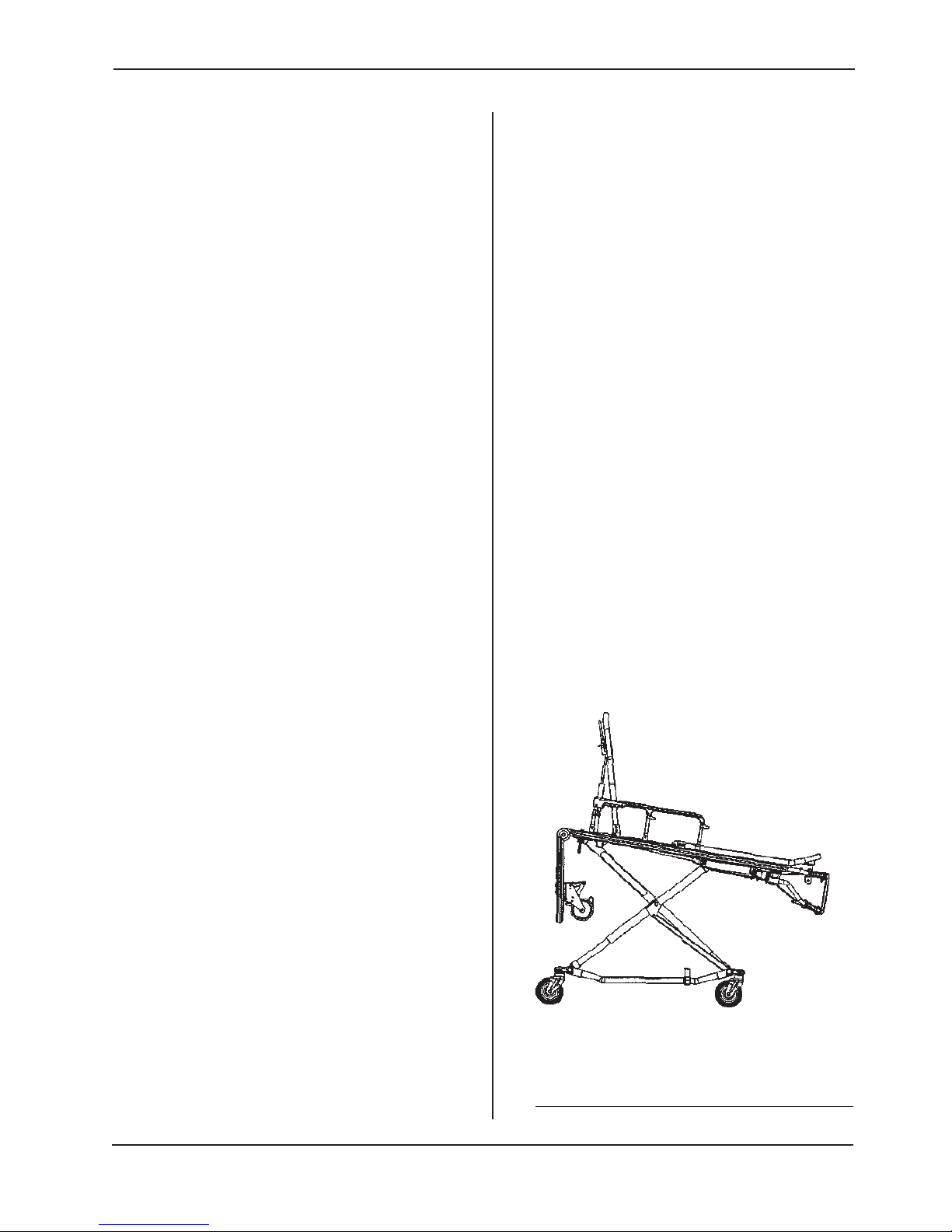
To raise/lower the cot from the foot end:
1. Standing at the foot end of the cot, grasp the lower foot end lift tube.
2. Tip the cot up onto the load wheels (Figure 25).
3. Squeeze and hold the release handle and raise or lower the foot end to the desired position.
4. Lower the cot back onto the four base wheels (Figure 26).
Figure 25 - Cot Tipped on Load Wheels Figure 26 - Cot Lowered to Ground
To raise/lower the cot from the side:
1. Place one foot on the outer base tube.
2. Grasp the side release handle with one hand. Place your other hand on the outer support rail to help stabilize the
cot (Figure 27).
3. Squeeze the side release handle and raise or lower the cot to the desired position.
WARNING
If lowering the cot to the lowest position (position 1), remove your foot from the base tube or injury could result (Figure
28).
Figure 27 - Holding Outer Support Rail
Return To Table of Contents
32 6082-209 -001 R EV A w ww.stryker.com
Figure 28 - Lowering Cot From Side
Page 33
ADJUSTING THE LEG REST
Cot Features
A
B
FOOT END
Figure 29 - Leg Rest Elevated
The leg rest is adjustable to allow for elevation of the patient’s legs.
To raise the leg rest, lift the leg rest frame (A) as high as possible. The support bracket will engage automatically.
Release the frame after the support bracket has engaged.
To lower the leg rest, lift the leg rest frame (A) and, while holding the frame, lift up on the release handle
(B) until the bracket disengages. Lower the leg rest until flat.
www.stryker.com 6082-209 -001 REV A 33
Return To Table of Contents
Page 34

Cot Features
OPERATING THE BACKREST
To raise, squeeze handle (A) for pneumatic assist in lifting the Backrest to the desired height. Remove hand(s) from
handle when desired height is achieved.
To l ow er, squeeze handle (A) and push down on the Backrest frame until the Backrest has reached the desired height.
Remove hand(s) from handle when desired height is achieved.
A
B
HEAD END
Figure 30 - Backrest Elevated and Siderails Raised
OPERATING THE SIDERAILS
To raise, lift up until the latch clicks and the siderail locks into place. When a patient is on the cot, always keep the
siderails in the raised position unless the patient is being transferred.
To l ow er, squeeze handle (B) to release the siderail latch. Guide the siderail down toward the foot end until flat.
WARNING
Siderails are not intended to serve as a patient restraint device. Refer to page 20 for proper restraint strap usage.
Failure to utilize the siderails properly could result in patient injury.
Return To Table of Contents
34 608 2-209 -001 REV A w ww.stryker.com
Page 35

Cot Features
OPERATING THE BREAKAWAY HEAD SECTION
The head end of the cot litter folds down to shorten the length of the cot and allow for maneuvering when space is
limited in elevators, halls, etc.
The breakaway head section should only be used when the cot is in positions 5−7 (see page 19).
WARNING
Operating the cot with the breakaway head section lowered may cause injury to the patient or operator or damage to the
cot. Use only positions 5−7 (see page 19) when using this configuration.
A
Figure 31 - Breakaway Head Section Release Bar
To lower the breakaway head section, raise the backrest to its uppermost position (see page 35 for backrest
operation instructions). Squeeze the release bar (A) at the head end of the cot with one hand while supporting the
head section with the other hand. Lower the head section.
To raise the breakaway head section, lift the breakaway head section until the release bar clicks and the head section
locks into place.
Figure 32 - Lowered Breakaway Head Section
CAUTION
Damage to the cot can occur if the cot is lowered in the shortened position. Use only positions 5−7 (see page 19)
when the cot is shortened.
www.stryker.com 6082-209 -001 REV A 35
Return To Table of Contents
Page 36

Cot Features
OPERATING THE TWO-STAGE I.V. POLE (OPTIONAL EQUIPMENT)
D
C
B
Figure 33 - Two-Stage I.V. Pole Storage Position
A
Figure 34 - Two-Stage I.V. Pole
1. Lift and pivot the pole from the storage position and push down until it is locked into receptacle (A).
2. To raise the height of the pole, turn the lock actuator (B) counterclockwise and pull up on the telescoping portion
(C) of the pole to raise it to the desired height.
3. Turn the lock actuator (B) clockwise to lock the telescoping portion in place.
4. Hang I.V. bags on the I.V. hook (D).
CAUTION
The weight of the I.V. bags or equipment must not exceed 40 pounds.
Return To Table of Contents
36 6082-209 -001 RE V A www.stryker.com
Page 37

Cot Features
OPERATING THE THREE-STAGE I.V. POLE (OPTIONAL EQUIPMENT)
1. Lift and pivot the pole from the storage position and push down until it is
locked into receptacle (A).
2. To raise the height of the pole, turn the lock actuator (B) counterclockwise
and pull up on the bottom telescoping portion (C) of the pole to raise it to
the desired height.
3. Turn the lock actuator (B) clockwise to lock the bottom telescoping portion
in place.
4. For a higher I.V. pole, pull up on section (D) until the spring clip (E) engages.
5. Hang I.V. bags on the I.V. hook (F).
6. To lower the I.V. pole, push in on the spring clip (E) and slide section (D)
down into section (C). Turn the lock actuator (B) counterclockwise and
slide section (C) into the bottom tube.
7. Lift up and pivot the pole down into the storage position.
CAUTION
The weight of the I.V. bags or equipment must not exceed 40 pounds.
F
D
E
C
B
Figure 35 - Three-Stage I.V. Pole Storage Position
www.stryker.com 6082-209 -001 REV A 37
A
Figure 36 - Three-Stage I.V. Pole
Return To Table of Contents
Page 38

Cleaning
The cot is designed to be power washable. The unit may show some signs of oxidation or discoloration from continuous
washing, however, no degradation of the cot’s performance characteristics or functionality will occur due to power
washing as long as the proper procedures are followed.
Clean Velcro AFTER EACH USE. Saturate Velcro with disinfectant and allow disinfectant to evaporate. (Appropriate
disinfectant for nylon Velcro should be determined by the hospital.)
WASHING LIMITATIONS
WARNING
Use any appropriate personal safety equipment (goggles, respirator, etc.) to avoid the risk of inhaling contagion. Use of
power washing equipment can aerate contamination collected during the use of the cot.
CAUTION
• DO NOT STEAM CLEAN OR ULTRASONICALLY CLEAN THE UNIT
• Maximum water temperature should not exceed 180°F/ 82°C.
• Maximum air dry temperature (cart washers) is 240°F /115°C.
• Maximum water pressure should not exceed 1500 psi/130.5 bar. If a hand held wand is being used to wash the
unit, the pressure nozzle must be kept a minimum of 24 inches/61 cm from the unit.
• Towel dry all casters and interface points.
• After washing the cot, follow the lubrications procedure on page 41.
• Failure to comply with these instructions may invalidate any/all warranties.
Return To Table of Contents
38 6082 -209 -001 RE V A ww w.stryker.com
Page 39

Cleaning
In general, when used in those concentrations recommended by the manufacturer, either phenolic type or quaternary
(excluding Virex® TB) type disinfectants can be used. Iodophor type disinfectants are not recommended for use
because staining may result.
Suggested cleaners for the cot surface:
• Quaternary Cleaners (active ingredient - ammonium chloride)
• Phenolic Cleaners (active ingredient - o-phenylphenol)
• ChlorinatedBleachSolution(5.25%-lessthan1partbleachto100partswater)
Avoid over saturation and ensure the product does not stay wet longer than the chemical manufacturer’s guidelines
for proper disinfecting.
WARNING
• SOME CLEANING PRODUCTS ARE CORROSIVE IN NATURE AND MAY CAUSE DAMAGE TO THE PRODUCT IF
USED IMPROPERLY. If the products described above are used to clean Stryker patient care equipment, measures
must be taken to insure the cots are wiped with a cloth soaked in clean water and thoroughly dried following
cleaning.
• Failure to properly rinse and dry the cots will leave a corrosive residue on the surface of the cots, possibly causing
premature corrosion of critical components.
Note: Failure to follow the above directions when using these types of cleaners may void this product’s warranty.
REMOVAL OF IODINE COMPOUNDS
Use a solution of 1-2 tablespoons Sodium Thiosulfate in a pint of warm water to clean the stained area. Clean as soon
as possible after staining occurs. If stains are not immediately removed, allow solution to soak or stand on the surface.
Rinse surfaces which have been exposed to the solution in clear water before returning unit to service.
WARNING
Failure to properly clean or dispose of contaminated mattress or cot components will increase the risk of exposure to
blood borne pathogens and may cause injury to the patient or the operator.
www.stryker.com 6082-209 -001 REV A 39
Return To Table of Contents
Page 40

Preventative Maintenance
Operation Schedule Procedure
Cleaning and Disinfecting Each Use. See page 38
For 1-25 calls per month, inspect cot
every 6 months
Inspection
Note: Keep up to date maintenance records using the Maintenance Record form on page 43.
For 26-200 calls per month, inspect
cot every 3 months
For 200+ calls per month, inspect cot
monthly.
See below for checklist
CHECKLIST
_____ All fasteners secure (reference all assembly drawings)
__ ___ All welds intact, not cracked or broken
__ ___ No bent or broken tubing or sheet metal
__ ___ No debris in wheels
__ ___ All wheels secure, rolling and swiveling properly
__ ___ Optional wheel lock holds wheel securely when on and clears wheel when off
__ ___ Siderails move an latch properly
_____ Backrest operating properly
_____ Optional accessories intact and operating properly
_____ Height positioning latch functioning properly
__ ___ Cot secure in each height position
_____ Undercarriage folds properly
_____ Breakaway head section operating properly
__ ___ Safety bar operating properly
_____ Foot rest operating properly
__ ___ No rips or cracks in mattress cover
__ ___ Body restraints intact and working properly
_____ Lubricate base tubes (optional)
Serial Number:
Completed by: _______________________________________ Date: _________________
Return To Table of Contents
40 6082-209-001 REV A www.stryker.com
Page 41
Preventative Maintenance
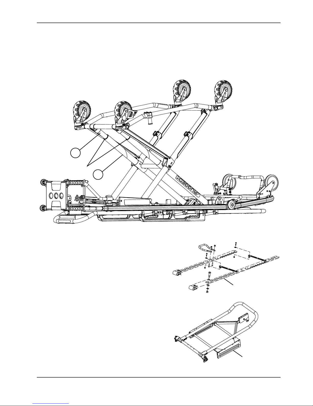
BASE LUBRICATION
Note: The MX−PR O® has been designed to operate without the need for lubrication. Tri−Flow™ with Teflon® lubricant
may be used to reduce the force required to raise the undercarriage and to minimize wear. Do not use silicone,
WD−40™, or lithium grease. They could harm the moving parts of the cot.
FOOT END
B
APPLY LUBRICATION
A
Figure 37 - Base Lubrication Locations
1. Place the cot in the highest position.
2. Turn the cot upside down with the base legs facing up.
3. Using the plastic applicator tube, spray Tri−Flow™ with
Teflon® lubricant (Stryker part number 6082−199−12) in
the gap between the upper (item A) and lower lift tubes
(item B) on both foot end legs.
4. Apply Tri−Flow™ to right and left height adjustment
Height Adjustment Racks racks providing an even
application.
5. Apply Tri−Flow™ to the right and left slide plates
providing an even application.
6. Let the cot sit for 5 minutes.
7. Turn the cot back over. Raise and lower the cot a
few times to work the lubricant throughout the applied
areas.
8. Wipe any excess lubricant from the base tubes. Slide
Plates
Height Adjustment Racks
Slide Plates
www.stryker.com 6082-209 -001 REV A 41
Return To Table of Contents
Page 42

Preventative Maintenance
PNEUMATIC BACKREST ADJUSTMENT
Tools Required:
1/2” Wrench 5/32” Allen Wrench Locktite 3/32” Allen Wrench
Adjustment Procedure:
1. For easier access, move the backrest to 75 degrees.
Note: Before continuing with the backrest adjustment procedure, be sure the cylinder (item A) is completely
threaded into the yoke (item B) so no threads are showing on the shaft of the cylinder. If threads are showing,
use a 3/32” Allen wrench to remove the set screw (item C) in the center of the yoke and remove the E−clip and
pin (items D & E) holding the bottom of the pneumatic cylinder. Thread cylinder shaft (item A) completely into
yoke (item B). Replace the E−clip and pin (items D & E) and replace the set screw (item C) using Locktite.
2. Using a 1/2” wrench, loosen the hex nut (item F) on the backrest pivot (item J) while holding the set screw (item
H) fixed in the pivot.
3. Using a 5/32” Allen wrench, turn the set screw (item H) until there is no play between the backrest release handle
A
K
J
H
F
C
B
D
E
Figure 38 - Pneumatic Cylinder and Fowler Crossbrace
(item K) and the pneumatic cylinder release button.
4. Be sure the backrest will travel from flat to at least 75 degrees. If it doesn’t, turn the set screw (item H) clockwise
1/2 turn. Repeat until at least 75 degrees of travel is achieved.
5. Lower the backrest to a 5−10 degree angle and release the handle. Apply approximately 50 pounds downward
force to the end of the backrest. If the backrest drifts down, turn the set screw (item H) counterclockwise. Repeat
until the backrest does not drift downward.
6. Using the 1/2” wrench, tighten the hex nut (item F) while holding the set screw (item H) fixed in the pivot.
Return To Table of Contents
42 6082-209 -001 REV A www.stryker.com
Page 43

Maintenance Record
Date Maintenance Operation Performed By Hours
www.stryker.com 6082-209 -001 REV A 43
Return To Table of Contents
Page 44

Training Record
Training Date Training Method
Trainee Name Basic
Training
Refresher
Update
Owner’s Manual, In-Service,
Formal Class, Etc.
Return To Table of Contents
44 6082-209-001 RE V A ww w.stryker.com
Page 45

6082-150-011 Rev P (Reference Only)
Cot Assembly
www.stryker.com 6082-209 -001 REV A 45
Return To Table of Contents
Page 46

Cot Assembly
Return To Table of Contents
46 6082-209-001 REV A www.stryker.com
Page 47
Cot Assembly
www.stryker.com 6082-209 -001 REV A 47
Return To Table of Contents
Page 48

Cot Assembly
Return To Table of Contents
48 6082- 209- 001 REV A www.stryker.com
Page 49

Cot Assembly
www.stryker.com 6082-209 -001 REV A 49
Return To Table of Contents
Page 50

Cot Assembly
Cot Assembly - 6082-150-011 Rev P (Reference Only)
Item Part No. Part Name Qty.
A 6082-101-011 Base Assembly (page 51) 1
B 6082-205-050 Litter/Base Adapter Assy., Right
(page 63) 1
C 6082-205-053 Litter/Base Adapter Assy., Left
(page 64) 1
D 6082-205-060 Litter/Base Adapter Spacer Sleeve 2
E 6082-130-011 Litter Assembly (page 65) 1
F 0004-135-000 Button Head Cap Screw 2
G 0004-204-000 Button Head Cap Screw 2
H 6060-037-026 Pivot Spacer Plate 2
J 6060-037-035 Outer Rail End Cap 2
K 6082-037-010 Breakaway Head Section Assembly 1
L 0004-198-000 Button Head Cap Screw 7
M 0016-028-000 Hex Nut 10
N 1010-031-077 Gas Spring 1
P 0014-021-000 Washer 2
Q 6082-031-046 Litter/Base Interface Pivot Spacer 2
R 0011-448-000 Washer 2
S 6082-031-031 Clevis Pin 1
T 0028-181-000 Truarc Ring 1
U 0011-355-000 Washer 2
V 0004-325-000 Button Head Cap Screw 2
W 6082-033-037 Retainer Plate Cover, Right 1
X 6082-033-036 Retainer Plate Cover, Left 1
Y 0037-082-000 Vibration Mount 2
Z 6080-030-043 Litter Frame Bumper 2
AA 0038-508-000 Extension Spring 2
AB 6060-090-002 Serial Number Tag 1
AC 0025-079-000 Blind Rivet 2
AE 6082-090-043 Label, Stryker 2
AF 6060-090-004 Label, Small 1
AG 6060-090-114 Label, Keep Hands Clear 2
AH 6070-090-107 Label, Lift to Release 1
AJ 6082-090-045 Label, MX-PRO R3 1
AK 6080-090-108 Label, Lift Here 2
AL 6080-090-009 Label, Warning 1
AM 6082-090-110 Label, MX−PRO R3 2
AN 6082-090-040 Label, MX-PRO Tube, Left 1
AP 0946-001-155 Bumper 2
AR 0025-133-000 Blind Rivet 2
AS 0008-033-000 Socket Head Shoulder Bolt 1
AT 0016-028-000 Hex Nut 1
AU 6082-040-025 Link Bushing 2
AV 0011-352-000 Washer 1
AX 6082-090-039 Label, MX−PRO Tube, Right 1
AZ 6082-090-004 Label, Side Release 1
BA 0025-132-000 Flange Rivet 4
BB 6082-001-085 2” Adhesive Loop Pile 2
BC 6082-090-046 Label, 650 lb Weight Capacity 2
Return To Table of Contents
50 6082-209 -001 REV A www.stryker.com
Page 51

6082-101-011 Rev G (Reference Only)
Base Assembly
www.stryker.com 6082-209 -001 REV A 51
Return To Table of Contents
Page 52

Base Assembly
LEFT HAND OPTION SHOWN
Return To Table of Contents
52 6082-209 -001 REV A www.stryker.com
RIGHT HAND OPTION SHOWN
Page 53

Base Assembly
NOITPOKCARTHGIEHDRADNATS
NOITPOKCARTHGIEHDEDNETXE
www.stryker.com 6082-209 -001 REV A 53
Return To Table of Contents
Page 54

Base Assembly
Base Assembly - 6082-101-011 Rev G (Reference Only)
Item Part No. Part Name Qty.
A 6060-001-021 Caster Mount Cover 4
B 6060-001-030 Center Base Spacer 1
C 6060-001-031 Inner Base Spacer, Foot End 1
D 6060-001-032 Inner Base Spacer, Head End 1
E 6060-001-070 Upper Frame Tube Bearing 8
F 6060-001-071 Lower Frame Tube Bearing 8
G 6060-002-010 6” Wheel Assembly (page 55) 4
H 6060-005-029 Height Adj. Rack Mounting Pivot 2
J 6060-005-044 Lock Bar Slide Bearing 2
K 6083-101-050 Outer Base Tube Assy. 2
L 6060-101-028 Base Connecting Rod 1
M 6060-201-053 Litter Pivot Outer Lift Tube 2
N 6080-001-029 Outer Base Spacer, Head End 2
P 6080-001-046 Support Link 2
Q 6090-001-009 Caster Nut 4
R 0003-205-000 Hex Head Cap Screw 4
S 0003-353-000 Hex Head Cap Screw 4
T 0008-010-000 Shoulder Bolt 4
U 0004-197-000 Button Head Cap Screw 2
V 0008-028-000 Socket Head Shoulder Bolt 2
W 0008-045-000 Socket Head Shoulder Bolt 2
X 0011-224-000 Nylon Washer 8
Y 0016-028-000 Hex Nut 4
Z 0025-133-000 Blind Rivet 4
AA 0037-225-000 Hole Plug 4
AB 0011-004-000 Washer 4
AC 0011-350-000 Washer 4
AD 0016-035-000 Hex Nut 2
AE 0016-060-000 Hex Nut 4
AF 0016-089-000 Hex Nut 2
AG 6082-001-027 Connecting Rod Bearing 4
AH 6082-101-043 Base Tube 2
AJ 6082-201-067 Base Pivot Outer Lift Tube Assy.
(page 56) 2
AK 6082-001-069 Base Pivot Inner Lift Tube Assy.
(page 57) 2
AL 0025-116-000 Dome Head Blind Rivet 8
AM 6082-005-026 Side Release Handle 1
AN 6082-005-038 Height Adj. Rack Cross Brace 2
AP 6082-005-056 Lock Bar Assembly (page 58) 1
AQ 6082-101-055 Litter Pivot Inner Lift Tube 2
AR 0081-244-000 Flange Bearing 16
AS 0016-002-000 Fiberlock Nut 4
6082-039-000 Rev A Standard Height
BA 6082-105-057 Height Adj. Rack, Left 1
BB 6082-305-052 Height Adj. Rack, Right 1
Return To Table of Contents
54 608 2-209 -001 REV A w ww.stryker.com
6082-040-000 Rev A Extended Height
CA 6082-343-082 Height Adj. Rack, Right 1
CB 6082-343-083 Height Adj. Rack, Left 1
Page 55
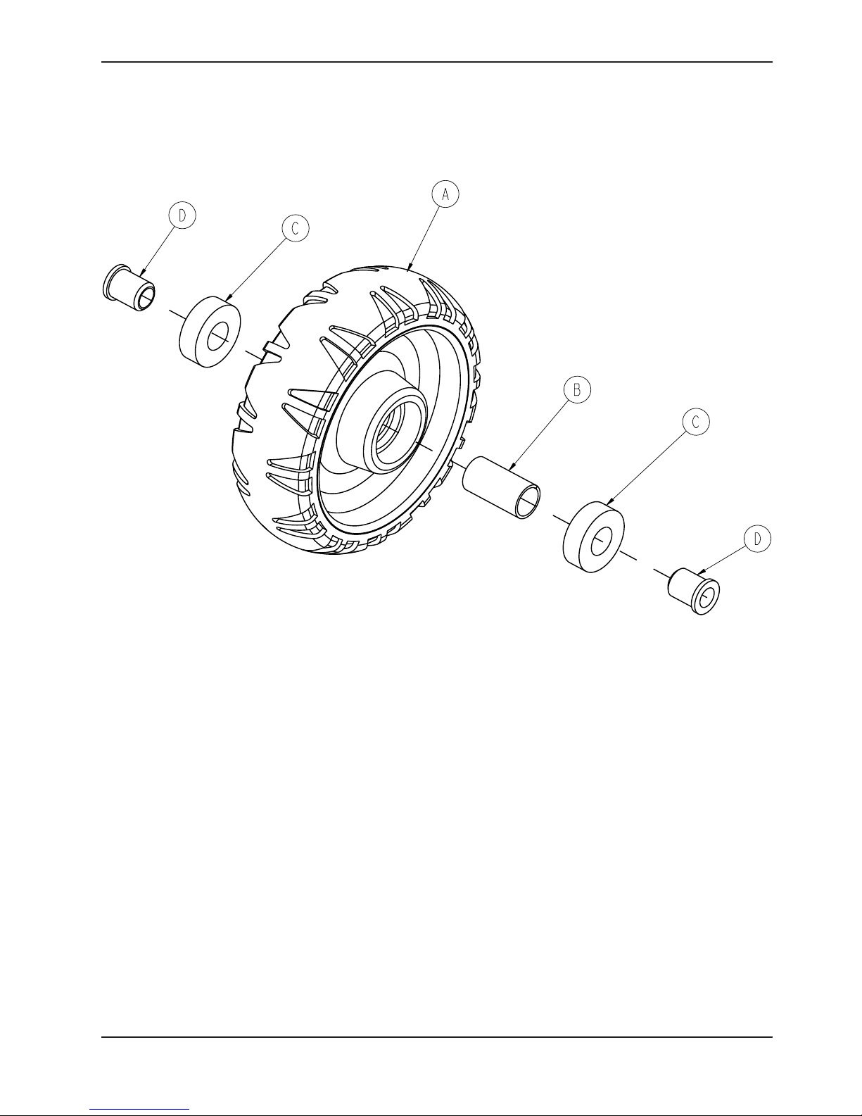
Wheel Assembly - 6060-002-010
Rev B
Item Part No. Part Name Qty.
A 6060-002-045 6 In Molded Wheel 1
B 6060-002-046 Bearing Spacer 1
C 0081-226-000 Bearing 2
D 0715-001-255 Wheel Bushing 2
Return To Table of Contents
www.stryker.com 6082-209 -001 REV A 55
Page 56

Base Pivot Outer Lift Tube Assembly - 6082-201-067
Rev B
Item Part No. Part Name Qty.
A 0025-079-000 Dome Head Pop Rivet 4
B 6085-001-112 Inner Leg Bumper 1
C 6082-101-057 Base Pivot Outer Lift Tube Weldment 1
D 6085-001-126 Hot Drop Dampener Retainer 1
Return To Table of Contents
56 6082-209 -001 REV A www.stryker.com
Page 57

Base Pivot Inner Lift Tube Assembly - 6082-001-069
Rev A
Item Part No. Part Name Qty.
A 6082-001-059 Inner Lift Tube Weldment 1
B 0025-079-000 Blind Rivet 2
C 6082-101-035 Hot Drop Dampener 1
D 6082-001-036 Hot Drop Dampener Sleeve 1
Return To Table of Contents
www.stryker.com 6082-209 -001 REV A 57
Page 58
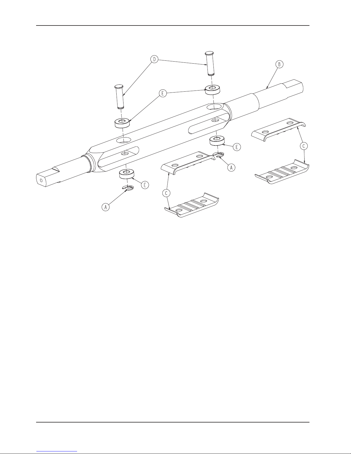
Lock Bar Assembly - 6082-005-056
Rev -
Item Part No. Part Name Qty.
A 0028-181-000 Truarc Ring 2
B 6082-005-055 Height Adjustment Rack Lock Bar 1
C 6082-005-065 Lock Bar Slide Plate 4
D 6082-005-096 Height Adjustment Rack Latch Pin 2
E 0081-248-000 Bearing 4
Return To Table of Contents
58 6082-209 -001 RE V A www.stryker.com
Page 59

Adjustable Caster Lock Assembly - 6082-200-010
Rev B
Item Part No. Part Name Qty.
A 6082-100-012 Caster Horn 1
B 6080-100-032 Spring 1
C 0011-456-000 Washer 1
D 0025-153-000 Semi-Tubular Rivet 2
E 6080-090-101 Label, Warning 2
F 6080-300-030 Adjustable Caster Lock Pedal 1
G 6080-200-041 Octagonal Sleeve 1
H 0004-098-000 Hex Socket Button Head Cap Screw 1
I 0016-118-000 Centerlock Nut 1
www.stryker.com 6082-209 -001 REV A 59
Return To Table of Contents
Page 60

Optional Single Wheel Lock Assembly - 6082-501-010
Item Part No. Part Name Qty.
A 6082-002-012 Caster Horn Assembly 3
B 6082-200-010 Adj. Caster Lock Assembly (page 59) 1
Rev B
Optional Dual Wheel Lock Assembly - 6082-502-010
Item Part No. Part Name Qty.
A 6082-200-010 Adj. Caster Lock Assembly (page 59) 2
B 6082-002-012 Caster Horn Assembly 2
Rev B
Return To Table of Contents
60 6082-209-001 RE V A ww w.stryker.com
Page 61

6082-500-010 Rev B (Reference Only)
No Wheel Lock Option
Item Part No. Part Name Qty.
A 6082-002-012 Caster Horn Assembly (page 62) 2
Dual Diagonal Wheel Lock Option
6082-503-010 Rev A (Reference Only)
Item Part No. Part Name Qty.
A 6082-002-012 Caster Horn Assembly (page 62) 2
B 6082-200-010 Adj. Caster Lock Assembly (page 59) 2
Four Wheel Lock Option
6082-504-010 Rev A (Reference Only)
Item Part No. Part Name Qty.
A 6082-200-010 Adj. Caster Lock Assembly (page 59) 4
www.stryker.com 6082-209 -001 REV A 61
Return To Table of Contents
Page 62
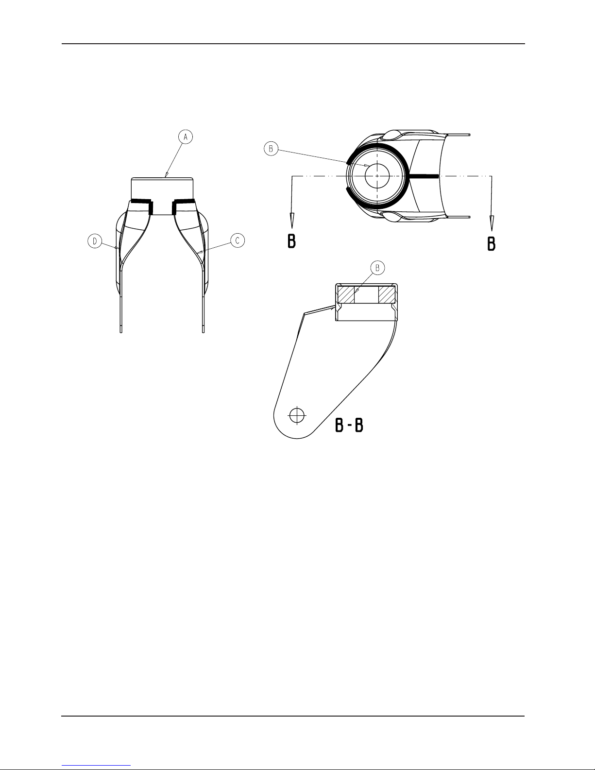
6082-002-012 Rev C (Reference Only)
Caster Horn Assembly
Item Part No. Part Name Qty.
A 6082-002-039 Bearing Retainer 1
B 0081-227-000 Bearing 1
C 6082-002-042 Caster Horn Plate, Left 1
D 6082-002-043 Caster Horn Plate, Right 1
Return To Table of Contents
62 608 2-209 -001 REV A w ww.stryker.com
Page 63
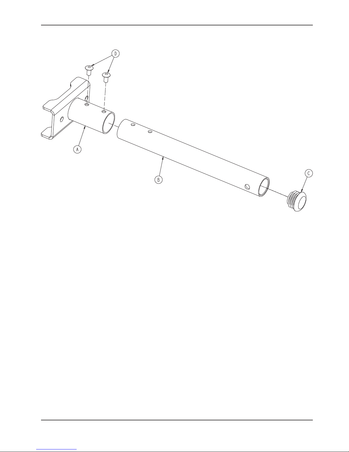
Litter/Base Adapter Assembly, Right - 6082-205-050
Rev A
Item Part No. Part Name Qty.
A 6082-005-034 Adapter Mounting Bracket, Right 1
B 6082-005-051 Adapter Pivot Tube 1
C 0037-225-000 Hole Plug 1
D 0025-079-000 Blind Rivet 2
Return To Table of Contents
www.stryker.com 6082-209 -001 REV A 63
Page 64

Litter/Base Adapter Assembly, Left - 6082-205-053
Rev A
Item Part No. Part Name Qty.
A 6082-005-035 Adapter Mounting Bracket, Left 1
B 6082-005-051 Adapter Pivot Tube 1
C 0037-225-000 Hole Plug 1
D 0025-079-000 Blind Rivet 2
Return To Table of Contents
64 6082-209 -001 REV A www.stryker.com
Page 65

6082-13 0-011 Rev K (Reference Only)
Litter Assembly
www.stryker.com 6082-209 -001 REV A 65
Return To Table of Contents
Page 66

Litter Assembly
Return To Table of Contents
66 6082 -209 -001 RE V A ww w.stryker.com
Page 67

Litter Assembly
www.stryker.com 6082-209 -001 REV A 67
Return To Table of Contents
Page 68

Litter Assembly
Return To Table of Contents
68 6082-209-001 RE V A ww w.stryker.com
Page 69

Litter Assembly
www.stryker.com 6082-209 -001 REV A 69
Return To Table of Contents
Page 70

Litter Assembly
Litter Assembly - 6082-130-011 Rev K (Reference Only)
Item Part No. Part Name Qty.
A 0721-031-065 Hole Plug 4
B 0938-001-177 Knob 1
C 0946-035-025 Liner 2
D 6060-032-038 Gas Spring Yoke 1
E 6060-032-040 Fowler Lift Pivot 1
F 6070-038-033 Calf Stand Retainer 1
G 0004-197-000 Button Head Cap Screw 8
H 0004-097-000 Button Head Cap Screw 4
J 0004-098-000 Button Head Cap Screw 1
K 0004-503-000 Button Head Cap Screw 4
L 0004-203-000 Button Head Cap Screw 6
M 0004-468-000 Button Head Cap Screw 12
N 0004-198-000 Button Head Cap Screw 4
Q 0004-204-000 Button Head Cap Screw 9
R 0015-050-000 Hex Nut 1
S 0004-597-000 Button Head Cap Screw 1
T 0008-027-000 Socket Head Set Screw 1
U 0016-028-000 Fiberlock Nut 4
V 0016-102-000 Nylock Nut 20
W 0025-079-000 Blind Rivet 52
X 0025-128-000 Blind Rivet 1
Y 0025-131-000 Semi-Tubular Rivet 2
Z 0025-133-000 Blind Rivet 8
AA 0081-255-000 Split Bearing 2
AB 0378-024-029 Slot Head Shoulder Bolt 1
AC 0721-026-066 Pivot Screw 6
AD 0014-067-000 Washer 2
AE 0014-055-000 Flat Washer 2
AF 0018-038-000 Hex Nut 4
AG 0021-180-000 Set Screw 1
AH 0021-138-000 Set Screw 1
AJ 0025-132-000 Blind Rivet 4
AK 0028-076-000 External Retaining Ring 2
AL 0056-016-000 Bumper 4
AM 6082-025-033 Pivot Mount Spacer 6
AN 6082-025-055 Pivot Mount 6
AP 6082-026-010 Siderail Assembly (page 72) 2
AQ 6082-030-031 Cross Brace Support Mount 4
AR 0016-078-000 Centerlock Nut 1
AS 6082-030-042 Litter Cross Brace 2
AT 6082-030-046 Outer Support Rail, Right 1
AU 6082-030-047 Outer Support Rail, Left 1
AV 6082-031-030 Litter/Base Interface 1
AW 6082-031-047 Litter/Base IF Pivot Spacer 1
AX 6082-032-045 Fowler Skin 1
AY 6082-032-050 Fowler Weldment 1
AZ 6082-032-052 Fowler Lift Release Handle 1
BA 6082-033-032 Slide Plate, Left 1
BB 6082-033-033 Slide Plate, Right 1
BC 6082-034-046 Midsection Skin 1
BD 6082-038-031 Calf Stand Support, Left 1
Return To Table of Contents
70 60 82-209-0 01 REV A www.stryker.com
Page 71

Litter Assembly
Litter Assembly - 6082-130-011 Rev K (Reference Only) - Continued
Item Part No. Part Name Qty.
BE 6082-038-032 Calf Stand Support, Right 1
BF 6082-038-035 Litter Crossbrace 2
BG 6082-038-045 Foot Section Skin 1
BH 6082-038-046 Foot Section Tube 1
BJ 6100-003-125 Straight “T” Pivot 4
Left Hand Release Option - 6082-040-001 Rev C
Item Part No. Part Name Qty.
CA 6082-140-059 Lift Bar Assembly (page 73) 1
Right Hand Release Option - 6082-040-002 Rev C
Item Part No. Part Name Qty.
CB 6082-140-060 Lift Bar Assembly (page 75) 1
Standard Height Litter Stop Option - 6082-041-000 Rev B
Item Part No. Part Name Qty.
DA 0004-097-000 Button Head Cap Screw 4
DB 6080-030-040 Litter Stop 2
DC 6060-090-114 Label, Warning 2
Extended Height Litter Stop Option - 6082-042-000 Rev B
Item Part No. Part Name Qty.
EA 0004-135-000 Button Head Cap Screw 4
EB 6082-343-081 Extended Litter Stop 2
EC 6082-090-114 Label, Keep Hands Clear 2
www.stryker.com 6082-209 -001 REV A 71
Return To Table of Contents
Page 72

Siderail Assembly - 6082-026-010
Rev B
Item Part No. Part Name Qty.
A 6060-025-024 Top Rail 1
B 6060-025-043 Spindle 3
C 6060-025-047 Spindle Lock 1
D 6060-025-041 Spindle Pivot 3
E 6060-025-040 Spindle Pivot Stop 2
F 6060-025-029 Lock Release Grip 1
G 6061-125-030 Lock Bar Casting 1
H 0038-344-000 Lock Release Compression Spring 1
J 6060-025-035 Pivot Bushing 4
K 0025-131-000 Rivet 4
Return To Table of Contents
72 60 82-209-0 01 REV A www.stryker.com
Page 73

Optional Lift Tube Assembly, Left Side Release - 6082-140-059
Rev B
1
www.stryker.com 6082-209 -001 REV A 73
1
Return To Table of Contents
Page 74

Optional Lift Tube Assembly, Left Side Release - 6082-140-059
Item Part No. Part Name Qty.
A 0004-135-000 Button Head Cap Screw 2
B 0008-033-000 Socket Head Shoulder Bolt 1
C 0016-028-000 Fiberlock Hex Nut 3
D 0025-079-000 Dome Head Rivet 14
E 0037-238-000 Tube Plug 4
F 6080-040-012 End Cap, Outer Rail, Foot End 2
G 6080-040-044 Spacer, Link Release 2
H 6082-040-021 Pull Handle Link 1
J 6082-040-025 Link Bushing, End 2
K 6082-040-061 Release Handle Assy. (page 77) 1
L 6082-130-038 Litter Stop, Foot End 2
M 6082-140-030 Lift Brace 1
N 6082-240-053 Lift Tube Assy., with Grips, Upper 1
P 6082-240-054 Lift Tube Assy., with Grips, Lower 1
Return To Table of Contents
74 6082-209 -001 REV A www.stryker.com
Page 75

Optional Lift Tube Assembly, Right Side Release - 6082-140-060
Rev B
1
1
www.stryker.com 6082-209 -001 REV A 75
Return To Table of Contents
Page 76

Optional Lift Tube Assembly, Right Side Release - 6082-140-060
Item Part No. Part Name Qty.
A 0004-135-000 Button Head Cap Screw 2
B 0008-033-000 Socket Head Shoulder Bolt 1
C 0016-028-000 Fiberlock Hex Nut 3
D 0025-079-000 Dome Head Rivet 14
E 0037-238-000 Tube Plug 4
F 6080-040-012 End Cap, Outer Rail, Foot End 2
G 6080-040-044 Spacer, Link Release 2
H 6082-040-025 Link Bushing, End 2
J 6082-040-029 Pull Handle Link 1
K 6082-040-062 Release Handle (page 78) 1
L 6082-130-038 Litter Stop, Foot End 2
M 6082-140-030 Lift Brace 1
N 6082-140-057 Lift Tube Assy., with Grips, Upper 1
P 6082-140-058 Lift Tube Assy., with Grips, Lower 1
Return To Table of Contents
76 6082-20 9-0 01 REV A www.stryker.com
Page 77

Release Handle Assembly, Left - 6082-040-061
Rev A
Item Part No. Part Name Qty.
A 0025-127-000 Rivet 4
B 6082-001-081 Release Handle 2
C 6082-140-034 Release Handle Brace 1
Return To Table of Contents
www.stryker.com 6082-209 -001 REV A 77
Page 78

Release Handle Assembly, Right - 6082-040-062
Rev A
Item Part No. Part Name Qty.
A 0025-127-000 Rivet 4
B 6082-001-081 Release Handle 2
C 6082-140-035 Release Handle Brace 1
Return To Table of Contents
78 60 82-209-0 01 REV A www.stryker.com
Page 79
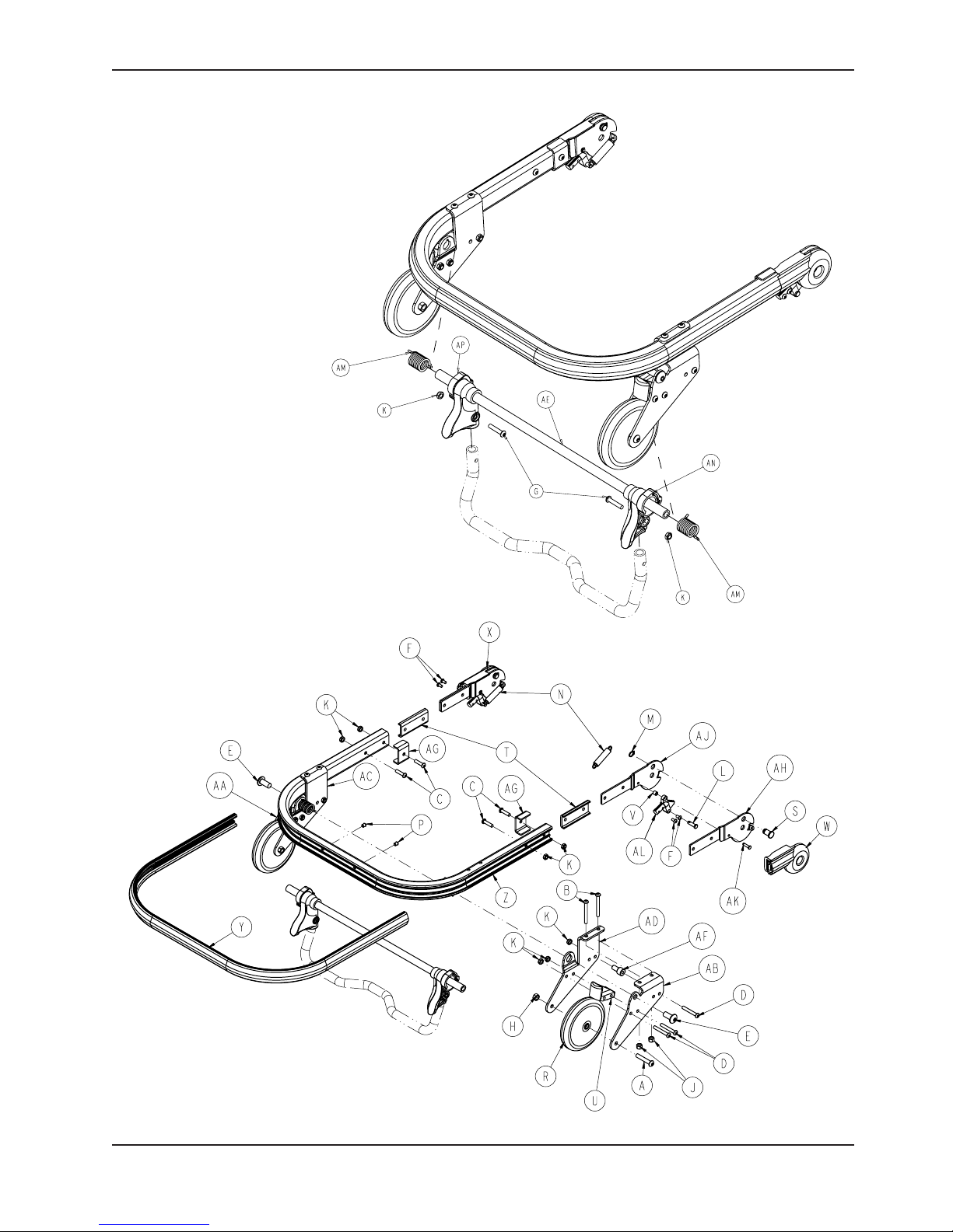
Breakaway Head Assembly
6080-037-055 Rev J (Reference Only)
www.stryker.com 6082-209 -001 REV A 79
Return To Table of Contents
Page 80

Breakaway Head Assembly
Breakaway Head Assembly - Standard Components - 6080-037-056 Rev N (Reference Only)
Item Part No. Part Name Qty.
A 0004-054-000 Button Head Cap Screw 2
B 0004-163-000 Button Head Cap Screw 4
C 0004-197-000 Button Head Cap Screw 4
D 0004-204-000 Button Head Cap Screw 6
E 0004-209-000 Button Head Cap Screw 2
F 0004-231-000 Button Head Cap Screw 4
G 0004-612-000 Button Head Cap Screw 2
H 0016-020-000 Centerlock Hex Jam Nut 2
J 0016-028-000 Fiberlock Hex Nut 4
K 0016-102-000 Nylock Hex Nut 12
L 0026-269-000 Clevis Pin 2
M 0028-138-000 External Retaining Ring 2
N 0038-410-000 Extension Spring 2
P 0721-031-065 Hole Plug 2
R 6060-036-020 Wheel Assembly, 5 inch 2
S 6060-036-024 Pivot Stop Pin, Breakaway Head 2
T 6060-037-026 Spacer Plate, Pivot 2
U 6060-037-033 Horn Stop Block, Breakaway Head 2
V 6060-037-036 Spacer, Trigger Lock, Pivot 2
W 6060-037-037 Pivot Cover, Right 1
X 6060-037-038 Pivot Cover, Left 1
Y 6080-036-044 Bumper 1
Z 6080-036-045 Outer Rail, Breakaway Head 1
AA 6080-037-027 Outer Caster Horn, Left 1
AB 6080-037-028 Outer Caster Horn Right 1
AC 6080-037-029 Inner Caster Horn, Left 1
AD 6080-037-030 Inner Caster Horn, Right 1
AE 6080-037-034 Pivot Tube, Safety Hook 1
AF 6080-037-049 Safety Hook, Rel. Handle, Spacer 2
AG 6082-037-025 Bracket, Litter/Base Adapter 2
AH 6082-037-042 Pivot, Form Right 2
AJ 6082-037-043 Pivot, Form, Left 2
AK 6082-037-057 Grooved Clevis Pin Assembly 2
AL 6090-037-039 Trigger Lock 2
AM 6500-001-321 Safety Bar Torsion Spring 2
AN 6500-001-323 Pivot, Safety Hook, Right 1
AP 6500-001-324 Pivot, Safety Hook, Left 1
Return To Table of Contents
80 6082 -209-001 RE V A ww w.stryker.com
Page 81

Breakaway Head Assembly
Breakaway Head Assembly - Standard Components - 6080-037-010 Rev K (Reference Only)
Item Part No. Part Name Qty.
BA 0014-067-000 Nylon Flat Washer 2
BB 0025-079-000 Dome Head Rivet 2
BC 0028-138-000 Retaining Ring 2
BD 6080-036-025 Pivot Pin 2
BE 6080-036-047 Crossbar, Release, Bent 1
BF 6080-037-055 Breakaway Head Section 1
Return To Table of Contents
www.stryker.com 6082-209 -001 REV A 81
Page 82

Breakaway Head Assembly
Breakaway Head Assembly - Standard Height Option - 6082-037-000 Rev A (Reference Only)
Item Part No. Part Name Qty.
CA 6082-037-040 Center Pivot, Head Section 2
Breakaway Head Assembly - Extended Height Option - 6082-038-000 Rev A (Reference Only)
Item Part No. Part Name Qty.
DA 6082-343-085 Center Pivot, Ext, Head Section 2
Return To Table of Contents
82 6082-209 -001 R EV A w ww.stryker.com
Page 83

Breakaway Head Assembly
Breakaway Head Assembly - Lift Option - 6091-156-016 Rev C (Reference Only)
Item Part No. Part Name Qty.
HG 6080-037-024 Breakaway Head Section Safety Bar 1
Return To Table of Contents
www.stryker.com 6082-209 -001 REV A 83
Page 84
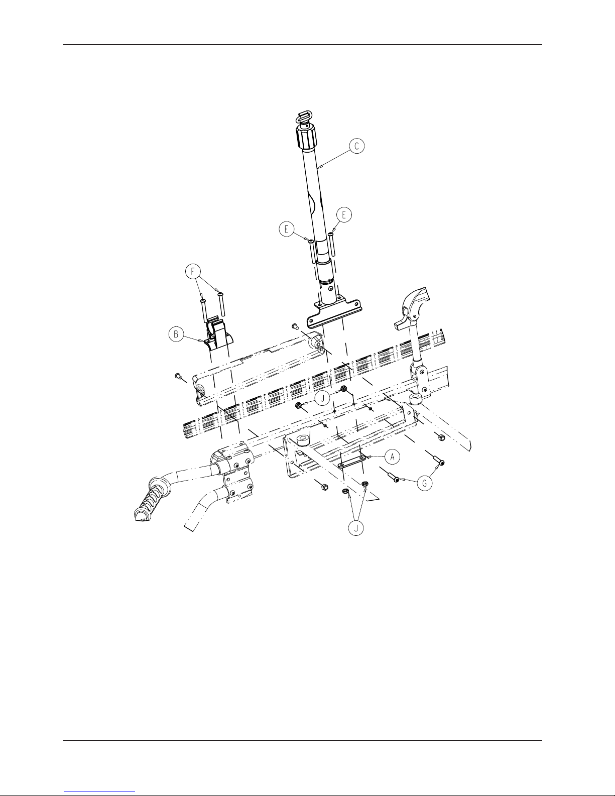
Optional Two-Stage I.V. Pole Assembly, Right - 6080-210-010
Optional Three-Stage I.V. Pole Assembly, Right - 6080-215-010
6080-210- 010 Rev B
Item Part No. Part Name Qty.
A 6070-110-032 I.V. Retainer Plate 1
B 6080-110-035 I.V. Clip 1
C 6080-210-020 Two-Stage I.V. Pole, Right
(page 85) 1
E 0004-097-000 Button Head Cap Screw 2
F 0004-163-000 Button Head Cap Screw 2
G 0004-198-000 Button Head Cap Screw 2
J 0016-102-000 Nylock Nut 4
Return To Table of Contents
84 6082-209 -001 REV A www.stryker.com
6080-215-010 Rev B
Item Part No. Part Name Qty.
A 6070-110-032 I.V. Retainer Plate 1
B 6080-110-035 I.V. Clip 1
C 6080-215-020 Three-Stage I.V. Pole, Right
(page 86) 1
E 0004-097-000 Button Head Cap Screw 2
F 0004-163-000 Button Head Cap Screw 2
G 0004-198-000 Button Head Cap Screw 2
J 0016-102-000 Nylock Nut 4
Page 85

Optional Two-Stage I.V. Pole Assembly, Right - 6080-210-020
Rev D
Item Part No. Part Name Qty.
A 6070-090-105 Label, Caution 1
B 6070-210-070 Two-Stage I.V. Pole Assembly
(page 85) 1
F 6080-090-031 Label, Specification 1
G 6080-210-053 I.V. Socket Weldment, Right 1
J 6070-110-037 I.V. Pivot Pin 1
K 0025-079-000 Dome Head Rivet 1
www.stryker.com 6082-209 -001 REV A 85
Return To Table of Contents
Page 86
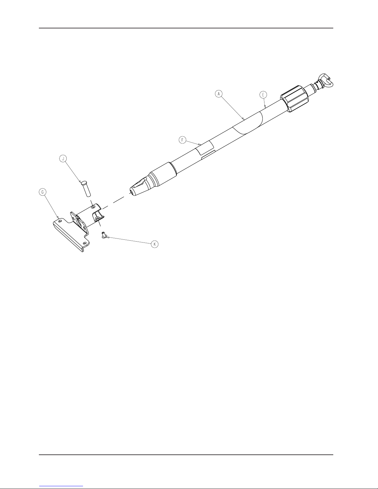
Optional Three-Stage I.V. Pole Assembly, Right - 6080-215-020
Rev C
Item Part No. Part Name Qty.
A 6070-090-105 Label, Caution 1
E 6070-215-070 Three-Stage I.V. Pole Assembly
(page 86) 1
F 6080-090-033 Label, Specification 1
G 6080-210-053 I.V. Socket Weldment, Right 1
J 6070-110-037 I.V. Pivot Pin 1
K 0025-079-000 Dome Head Rivet 1
Return To Table of Contents
86 6082-209 -001 RE V A www.stryker.com
Page 87

Optional Two-Stage I.V. Pole Assembly, Left - 6080-211-010
Optional Three-Stage I.V. Pole Assembly, Left - 6080-216-010
6080-211-010 Rev B
Item Part No. Part Name Qty.
A 6070-110-032 I.V. Retainer Plate 1
B 6080-110-035 I.V. Clip 1
C 6080-211-020 Two-Stage I.V. Pole, Left
(page 88) 1
E 0004-097-000 Button Head Cap Screw 2
F 0004-163-000 Button Head Cap Screw 2
G 0004-198-000 Button Head Cap Screw 2
J 0016-102-000 Nylock Nut 4
www.stryker.com 6082-209 -001 REV A 87
6080-216-010 Rev B
Item Part No. Part Name Qty.
A 6070-110-032 I.V. Retainer Plate 1
B 6080-110-035 I.V. Clip 1
C 6080-216-020 Three-Stage I.V. Pole, Left
(page 89) 1
E 0004-097-000 Button Head Cap Screw 2
F 0004-163-000 Button Head Cap Screw 2
G 0004-198-000 Button Head Cap Screw 2
J 0016-102-000 Nylock Nut 4
Return To Table of Contents
Page 88

Optional Two-Stage I.V. Pole Assembly, Left - 6080-211-020
Rev C
Item Part No. Part Name Qty.
A 6070-090-105 Label, Caution 1
B 6070-210-070 Two-Stage I.V. Pole Assembly
(page 90) 1
F 6080-090-032 Label, Specification 1
G 6080-211-053 I.V. Socket Weldment, Left 1
J 6070-110-037 I.V. Pivot Pin 1
K 0025-079-000 Dome Head Rivet 1
Return To Table of Contents
88 6082 -209 -001 RE V A ww w.stryker.com
Page 89
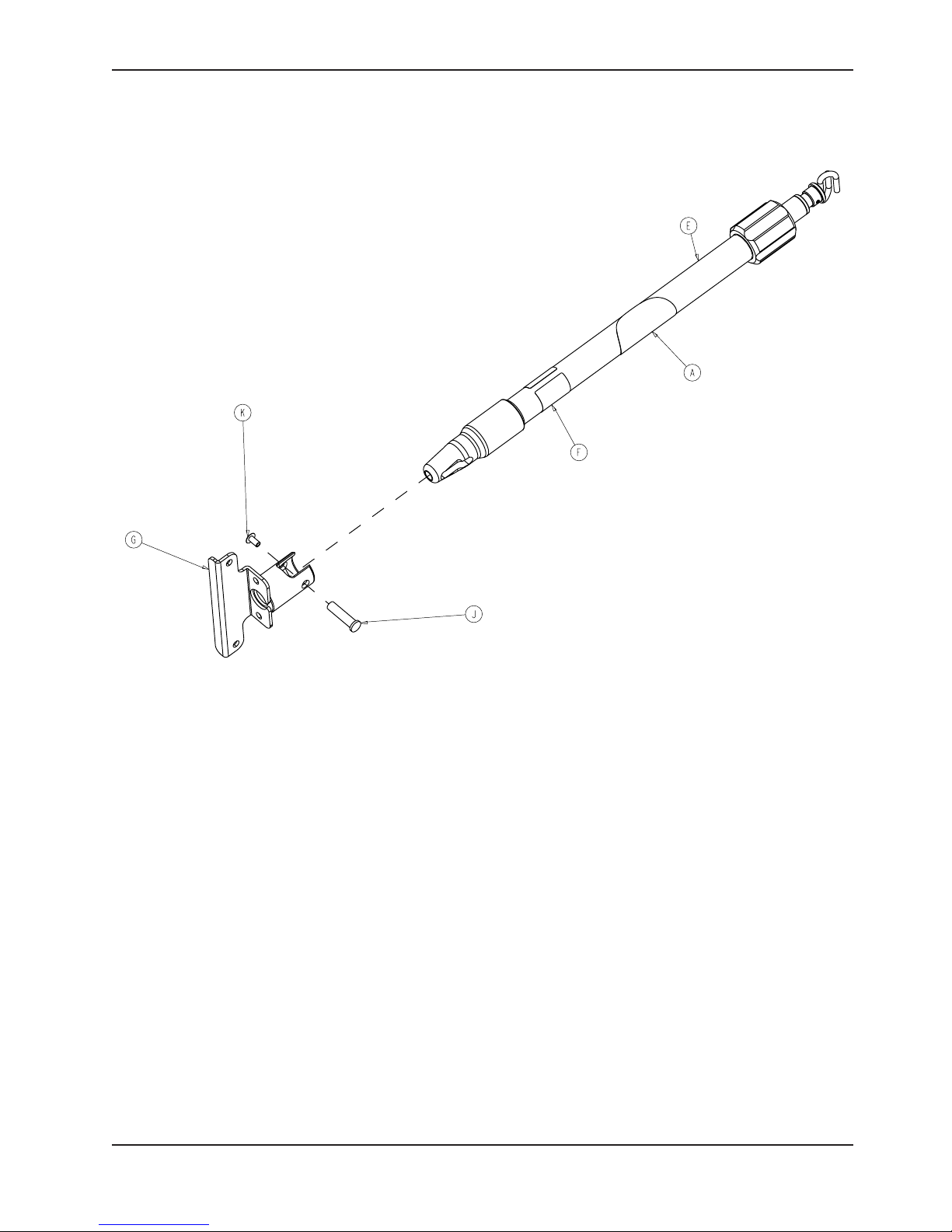
Optional Three-Stage I.V. Pole Assembly, Left - 6080-216-020
Rev C
Item Part No. Part Name Qty.
A 6070-090-105 Label, Caution 1
E 6070-215-070 Three-Stage I.V. Pole Assembly
(page 91) 1
F 6080-090-034 Label, Specification 1
G 6080-211-053 I.V. Socket Weldment, Left 1
J 6070-110-037 I.V. Pivot Pin 1
K 0025-079-000 Dome Head Rivet 1
Return To Table of Contents
www.stryker.com 6082-209 -001 REV A 89
Page 90

Optional Two-Stage I.V. Pole Assembly - 6070-210-070
Rev A
Item Part No. Part Name Qty.
A 1210-110-046 Back Up Ring 1
B 1210-110-047 Lock Ring 1
C 1210-110-049 Molded Actuator 1
D 6070-210-051 I.V. Base Tube 1
E 6070-110-042 Two-Stage Stage Tube 1
F 6070-110-051 Two-Stage Stage Slide Plug 1
G 6070-110-050 I.V. Hook Weldment 1
H 0026-006-000 Roll Pin 2
J 6070-110-012 I.V. Pole Pivot 1
Return To Table of Contents
90 6082-209-001 REV A www.stryker.com
Page 91

Optional Three-Stage I.V. Pole Assembly - 6070-215-070
Rev A
Item Part No. Part Name Qty.
A 1210-110-046 Back Up Ring 1
B 1210-110-047 Lock Ring 1
C 1210-110-049 Molded Actuator 1
D 6070-210-051 Base Tube 1
E 6070-110-051 Two-Stage Stage Slide Plug 1
F 6070-110-050 Hook Weldment 1
G 6070-115-030 Three-Stage Assembly (page 92) 1
H 6070-115-042 Two-Stage Stage Tube 1
I 6070-115-045 Bearing Plug 1
J 0026-005-000 Roll Pin 1
K 0026-006-000 Roll Pin 1
L 6070-110-012 I.V. Pole Pivot 1
Return To Table of Contents
www.stryker.com 6082-209 -001 REV A 91
Page 92

Optional Three-Stage I.V. Pole Assembly - 6070-115-030
Rev B
Item Part No. Part Name Qty.
A 6070-115-141 Spring Clip 1
B 6070-115-143 Three-Stage Stage Tube 1
C 6070-115-044 Three-Stage Stage Slide Plug 1
D 0026-004-000 Roll Pin 1
E 0045-139-000 O-Ring 1
Return To Table of Contents
92 6082-209 -001 REV A w ww.stryker.com
Page 93
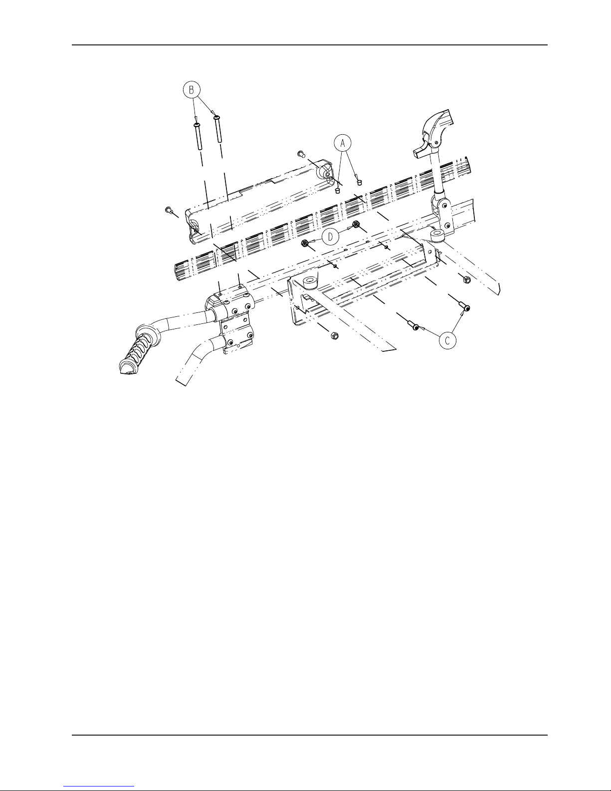
Patient Right Assembly, No I.V. Pole Option - 6080-212-010
Rev A
Item Part No. Part Name Qty.
A 0721-031-065 Hole Plug 2
B 0004-163-000 Hex Socket Button Head Cap Screw 2
C 0004-198-000 Button Head Cap Screw 2
D 0016-102-000 Nylock Nut 2
Return To Table of Contents
www.stryker.com 6082-209 -001 REV A 93
Page 94
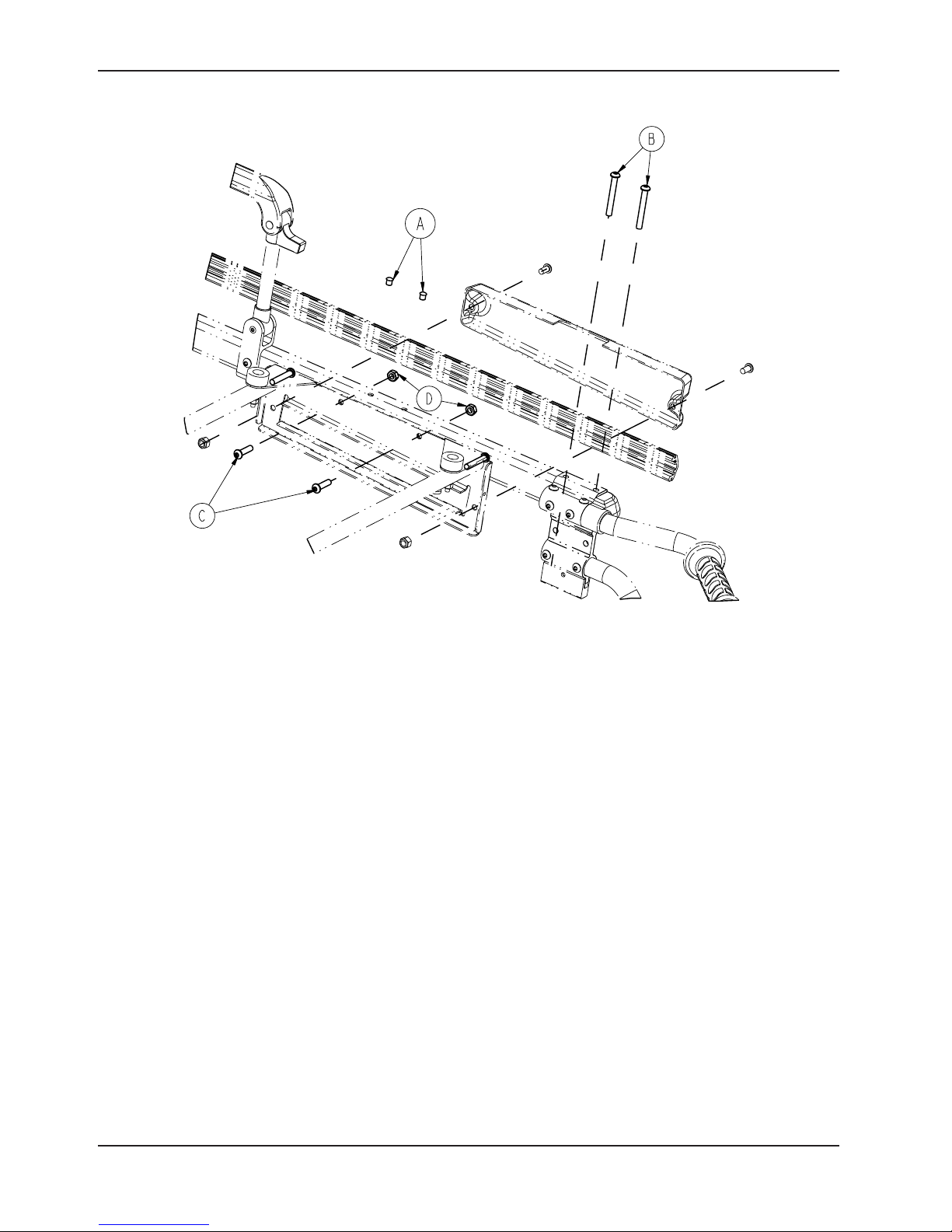
Patient Left Assembly, No I.V. Pole Option - 6080-213-010
Rev A
Item Part No. Part Name Qty.
A 0721-031-065 Hole Plug 2
B 0004-163-000 Hex Socket Button Head Cap Screw 2
C 0004-198-000 Button Head Cap Screw 2
D 0016-102-000 Nylock Nut 2
Return To Table of Contents
94 6082-209 -001 REV A w ww.stryker.com
Page 95

Optional Oxygen Bottle Holder, Removable - 6080-140-000
6080-140-010 Rev A (Reference Only)
Rev A
Item Part No. Part Name Qty.
A 6080-140-011 Oxygen Bottle Holder Hanger 2
B 6080-140-012 Oxygen Bottle Holder 1
Return To Table of Contents
www.stryker.com 6082-209 -001 REV A 95
Page 96

Optional Oxygen Bottle Holder, Foot End - 6070-140-000
6070-140-010 Rev D (Reference Only)
Rev A
Item Part No. Part Name Qty.
A 0025-079-000 Rivet 6
B 0004-862-000 Button Head Cap Screw 3
C 6080-090-109 Label, Warning 1
D 6060-140-013 Strap Assembly 2
E 6060-140-020 Tray Assembly (page 97) 1
F 6070-090-014 Label, Oxygen Bottle Holder Spec 1
G 6070-140-017 Support Bracket 1
H 0016-131-000 Nylock Hex Nut 3
J 0011-001-000 Washer 6
Return To Table of Contents
96 6082-209-001 RE V A ww w.stryker.com
Page 97

Optional Oxygen Bottle Holder Tray Assembly, Foot End
- 6060-140-020
Rev C
Item Part No. Part Name Qty.
A 0011-436-000 Washer 4
B 0025-133-000 Blind Rivet 7
C 0037-055-000 Black Protective Cap 4
D 0037-056-000 Retaining Washer 4
E 0946-001-155 Bumper 7
F 6060-140-015 Oxygen Bottler Holder Tray 1
www.stryker.com 6082-209 -001 REV A 97
Return To Table of Contents
Page 98

Optional Oxygen Bottle Holder, Head End - 6082-140-000
Rev F
Item Part No. Part Name Qty.
A 0004-197-000 Button Head Cap Screw 2
B 0016-102-000 Nylock Hex Nut 2
C 0025-079-000 Rivet 4
D 6082-140-040 Oxygen Bottle Holder Tray Assembly,
Head End (page 99) 1
E 6082-140-043 Strap Assembly 2
F 6082-140-044 Fowler Lift Release Handle Guard 1
Return To Table of Contents
98 6082 -209-001 RE V A ww w.stryker.com
Page 99

Optional Oxygen Bottle Holder Tray Assembly, Head End
- 6082-140-040
Rev C
Item Part No. Part Name Qty.
A 0004-455-000 Button Head Cap Screw 2
B 0011-199-000 Washer 2
C 0011-436-000 Washer 8
D 0016-028-000 Fiberlock Hex Nut 2
E 0025-099-000 Dome Head Rivet 2
F 0025-133-000 Dome Head Rivet 2
G 0029-003-000 Brass Eyelet 2
H 0037-055-000 Black Protective Cap 8
J 0037-056-000 Retaining Washer 8
K 0946-001-155 Bumper 2
L 6082-140-041 Oxygen Bottle Holder Tray, Head End 1
M 6082-140-042 Label, Oxygen Bottle Holder 1
N 6082-140-045 Oxygen Bottle Holder Bracket 1
P 0025-086-000 Blind Rivet 4
R 0056-016-000 Bumper 4
Return To Table of Contents
www.stryker.com 6082-209 -001 REV A 99
Page 100

Optional Pull Handle Assembly - 6080-155-000
Rev B
Item Part No. Part Name Qty.
A 6080-255-001 Pull Handle Bracket, Left 1
B 6080-255-002 Pull Handle Bracket, Right 1
C 6080-255-003 Pull Handle 1
D 0721-026-069 Upright Sleeve 2
E 0025-079-000 Dome Head Rivet 4
F 0004-130-000 Button Head Cap Screw 2
G 0025-133-000 Dome Head Pop Rivet 2
H 0016-036-000 Nylock Hex Nut 2
Return To Table of Contents
100 6082-209 -001 REV A www.stryker.com
 Loading...